Article

Grey Wolf and Weighted Whale Algorithm Optimized IT2 Fuzzy Sliding Mode Backstepping Control with Fractional-Order Command Filter for a Nonlinear Dynamic System

Department of Mechanical System Engineering, Dongguk University, Gyeongju 38066, Korea
Appl. Sci. 2021, 11(2), 489; https://doi.org/10.3390/app11020489
Submission received: 21 December 2020 / Revised: 3 January 2021 / Accepted: 4 January 2021 / Published: 6 January 2021

Abstract

:
In this study, a fractional-order sliding mode backstepping control method was proposed, which involved the use of a fractional-order command filter, an interval type-2 fuzzy logic system approximation method, and a grey wolf and weighted whale optimization algorithm for multi-input multi-output nonlinear dynamic systems. For designing the stabilizing controls of the backstepping control, a novel fractional-order sliding mode surface was suggested. Further, the transformed errors that occurred during the recursive design steps were easily compensated by the controllers constructed using a new fractional-order command filter. Thus, the differentiation issue of the virtual control in the conventional backstepping control design could be bypassed with a simpler controller structure. Subsequently, the unknown plant dynamics were approximated by an interval type-2 fuzzy logic system. The uncertainties, such as the approximation error and the external disturbance, were compensated by the fractional-order sliding mode control that was added in the backstepping controller. Furthermore, the controller parameters and the fuzzy logic system were optimized via a grey wolf and weighted whale optimization algorithm to obtain a faster tuning process and an improved control performance. Simulation results demonstrated that the fractional-order sliding mode backstepping control scheme provides enhanced control performance over the conventional backstepping control system. Thus, in this paper, a fractional-order sliding mode surface and fractional-order backstepping control are studied, which provide more rapid convergence and enhanced robustness. Furthermore, a hybrid grey wolf and weighted whale optimization algorithm are proposed to provide an improved learning performance than those of conventional grey wolf optimization and weighted whale optimization methods.

1. Introduction

Advanced nonlinear control methods are required to adapt to the rapid technical developments of several industrial fields. As a representative and outstanding nonlinear control method, the backstepping control (BSC) has been developed [1,2] and applied to various industrial systems by adopting a recursive controller design technique with a combination of a fuzzy logic system (FLS) [3] and neural networks (NNs) [4,5]. However, BSC is known to have a fatal issue that relates to the coupling order of the controller due to repeated differentiation of the virtual controls, which causes the phenomenon of “exploration of complexity”. As an alternative to bypass this issue of BSC, a dynamic surface control (DSC) system was developed [6]. The use of DSC combined with a FLS, an observer, and an adaptive law was also studied [7,8,9,10].
However, the inherent filtering error in the DSC system should be considered during the designing steps of the system. Moreover, the complexity of the steps involved in the controller design, and the stability proof appears due to the compensation of the filtering errors. Thus, bypassing the repeated differentiation of a virtual control can alter the BSC system into a better controller as compared to the DSC system. Based on this concept, in recent years, the finite-time command filter method, was studied to partially overcome these issues [11,12]. This method ensures the finite-time control convergence and prevents the repeated differentiation of the intermediate virtual control. However, the complexity issues associated with the design and robustness of the controller have not been addressed. In this study, a fractional-order finite-time command filter was considered to achieve an enhanced performance and a simpler controller structure as compared to those of the previous command filter based BSC control [11,12].
In recent decades, fractional-order operators [13,14] have garnered increasing significance in designing proportional-integral-derivative (PID) controllers [15], sliding mode controllers (SMC) [16,17,18], and adaptive controllers [19], owing to their better flexibility, robustness, and performance than those exhibited by their integer-order counterparts. We know that the sliding mode control (SMC) [20,21,22] exhibits a higher robustness to uncertainty if the states are reached within the sliding surface. In the conventional BSC, SMC was not directly combined to construct the virtual tracking error because the structure of the sliding mode surface in SMC is difficult to match the tracking error structure in the BSC system. In this paper, the fractional-order based sliding mode surface is used to construct the virtual tracking error of the BSC scheme, which imparts the benefits of SMC to the BSC system.
Next, a novel FLS, the interval type-2 FLS (IT2-FLS) [23], has been studied and extensively applied to control systems [24,25,26,27]. IT2-FLS is an extension of the type-1 FLS [28,29], which comprises the interval membership fuzzy functions. IT2-FLS has benefits such as more smoothness and robustness against uncertainty and more flexibility owing to its numerous tunable parameters, rendering it dealing with control applications. In this study, unknown dynamics of the nonlinear system are approximated via IT2-FLS.
Controller parameters are generally selected by the trial and error tuning method, depending on the experience of the designer. For numerous gain numbers to be adjusted, tuning processes become more time-consuming and require hard works. Thus, bio-inspired artificial optimal techniques, such as ant colony optimization (ACO) [30] and particle swarm optimization (PSO) [31], were developed to alleviate and optimize unknown system parameters under the condition of minimizing or maximizing the objective function.
The grey wolf optimization (GWO) technique [32] improved the optimization performance when compared to the traditional techniques of ACO and PSO that have been utilized for a few applications associated with robotic systems [33,34,35]. In this study, we proposed a new hybrid GWO and weighted whale optimization algorithm (WWOA) technique that demonstrated a better optimization performance than those of the conventional GWO and the whale optimization algorithm (WOA) [36,37]. This bio-inspired method bypasses the time consuming gain tuning of the designed controller and the IT2-FLS.
The main contributions of this paper are presented as follows: (1) an improved fractional-order command filter is proposed to avoid differentiation of the virtual controls in the BSC design procedures; (2) the design procedures of the BSC system become significantly easier to implement than conventional procedure by compensating for the filtering errors directly; (3) the use of a fractional-order sliding mode surface and a control are considered to improve the robustness and convergence time of the control system; (4) a new bio-inspired GWO-WWOA algorithm is proposed to obtain optimal tuning gains of the controller and the IT2-FLS. Therefore, bored tuning works for several parameters of the designed controller and fuzzy approximator can be alleviated and an improved control performance can be obtained.
Optimization and simulation results of an articulated manipulator system were presented to demonstrate the improved performance of the proposed optimization and control methods compared to those of the conventional methods.
This paper is organized as follows. Section 2 presents nonlinear dynamics, fractional order definition, IT2 fuzzy system, the controller design, the stability of the closed-loop system, and hybrid GWO and weight WOA. The results of optimization and simulation are presented in Section 3, and conclusions are given in Section 4.

2. Materials and Methods

2.1. Dynamic Equaiton of a Nonlinear MIMO System

Dynamic equations of a multi-input multi-output (MIMO) nonlinear system are described as follows [38]:
x ˙ i , j i = f i , j i ( x ¯ i , 1 , , x ¯ i , n i 1 , x i , 1 , , x i , n i 1 , u 1 , , u i 1 ) + g i , j i ( x ¯ i , 1 , , x ¯ i , n i 1 , x i , 1 , , x i , n i 1 , u 1 , , u i 1 ) x i , j i + 1 + d i , j i = f i , j i ( x ¯ i , 1 , , x ¯ i , n i 1 , x i , 1 , , x i , n i 1 , u 1 , , u i 1 ) + g 0 i , j i ( x ¯ i , 1 , , x ¯ i , n i 1 , x i , 1 , , x i , n i 1 , u 1 , , u i 1 ) x i , j i + 1 + g 0 i , j i ( x ¯ i , 1 , , x ¯ i , n i 1 , x i , 1 , , x i , n i 1 , u 1 , , u i 1 ) x i , j i + 1 + l i , j i , x ˙ i , n i = f i , n i ( x ¯ i , 1 , , x ¯ i , n i 1 , x i , 1 , , x i , n i , u 1 , , u i 1 ) + g i , n i ( x ¯ i , 1 , , x ¯ i , n i 1 , x i , 1 , , x i , n i , u 1 , , u i 1 ) u i + d i , n i = f i , n i ( x ¯ i , 1 , , x ¯ i , n i 1 , x i , 1 , , x i , n i , u 1 , , u i 1 ) + g 0 i , n i ( x ¯ i , 1 , , x ¯ i , n i 1 , x i , 1 , , x i , n i , u 1 , , u i 1 ) u i + l i , n i , y i = x i , 1 , j i = 1 , , n i 1 ,   i = 1 , , m ,
where x = [ x ¯ 1 , n 1 T , , x ¯ m , n m ] T R n is the state vector; x ¯ i , n 1 = [ x i , 1 , , x i , n 1 ] T R n 1 , x ¯ i , j i = [ x i , 1 , , x i , j i ] T R j i , and x ¯ i , n i 1 = [ x i , 1 , x i , n i 1 ] T R n i 1 are the partial state vector; u i R and y i R denote the input and output of the ith subsystem, respectively; f i , j i is unknown; g i , j i is partially known function; g i , j i = g 0 i , j i + Δ g i , j i , where g 0 i , j i is the known function, Δ g i , j i is the perturbation of g i , j i ; d i , j i is the bounded uncertainty, which includes the nonlinear dynamics and external disturbance; and l i , j i = Δ g i , j i x i , j i + 1 + d i , j i and l i , n i = Δ g i , n i u i + d i , n i are lumped uncertainties.
The aim of the design of the virtual controllers α i , j i and final controllers u i is to provide controllers for tracking the state variable x i , j i along with the command trajectory x f i , j i and the compensating uncertainties l i , j i , while ensuring that all signals are bounded and the errors of estimate and tracking are converged to zero in finite time.
Assumption 1.
The control gain function g i , j i , j i = 1 , , n i , i = 1 , , m , is bounded, and has known sign, and has its inverse matrix.
Assumption 2.
l i , j i is bounded and is satisfied with the unknown positive constants l i , j i l i , j i , j i = 1 , , n i , i = 1 , , m .

2.2. Fractional-Order Calculus

In this section, the definition and property of the fractional operator are presented. In the following, the concepts of fractional integral and derivative are presented by using the definitions of Riemann–Liouville. Further explanations and proofs of the theorems corresponding to these concepts are available in [14].
Definition 1
([14]). For n 1 < γ n ,    n N , the Riemann–Liouville fractional integration and derivative with order γ for function f ( t ) is defined by
D 0 R L t γ f ( t ) = 1 Γ ( γ ) 0 t f ( τ ) ( t τ ) 1 γ d τ
D 0 R L t γ f ( t ) = 1 Γ ( n γ ) d n d t n 0 t f ( τ ) ( t τ ) γ n + 1 d τ
where Γ ( · ) is the Gamma function.
Property 1 ([14]). For the Riemann–Liouville derivative, one obtains
D 0 R L t γ f ( t ) D 0 R L t β f ( t ) = D 0 R L t γ β f ( t )
where 0 β γ .

2.3. Function Approximation Using IT2 Fuzzy Logic Systems

The type-2 fuzzy set of system is a general type of the type-1 fuzzy system which can include uncertainties. A schematic diagram of an IT2-FLS is illustrated in Figure 1a. The structure of IT2-FLS is very similar to the conventional type-1 fuzzy logic system (T1- FLS) with an additional unit of ‘type reducer’. There are five units in the IT2-FLS, i.e., fuzzifier, fuzzy rules, an inference engine, a type-reducer, and defuzzifier. Figure 1b shows a Gaussian membership function (MF). By considering the rule base of IT2 fuzzy, the IT2 fuzzy rule is expressed as follows [23]:
R u l e i : I F    x 1 i s F ˜ 1 i , , a n d    x n    i s    F ˜ n i ,     t h e n    y 1    i s    G ˜ 1 i , , y m    i s G ˜ m i , i = 1 , , M
where n and m are the number of inputs and the outputs, respectively. M indicates the number of fuzzy rules to be considered for the IT2 fuzzy system. Then, x = [ x 1 , , x n ] are singletone inputs; y 1 , , y m are outputs of IT2 fuzzy; F ˜ i and G ˜ i are the membership functions of the antecedent and the consequent parts of the IT2 fuzzy rules, respectively. Using the firing strength F i for the ith rule, the IT2 function set is given as
F i = [ f l i    f h i ]
where f l i and f h i are defined as
f l i = μ l F ˜ 1 i ( x 1 ) × × μ l F ˜ n i ( x n ) = j = 1 n μ l F ˜ j i ( x j ) ,
f h i = μ h F ˜ 1 i ( x 1 ) × × μ h F ˜ n i ( x n ) = j = 1 n μ h F ˜ j i ( x j ) .
The center-of-sets (COS) type-reducer method combines firing intervals and the corresponding rule consequences as
Y cos j ( x ) = f i F i ( x ) , y j i Y i i = 1 M f i y j i i = 1 M f i = [ y l j , y r j ] ,   j = 1 , , m ,
where the defuzzified output is given as
y l j = i = 1 M f l i y l j i i = 1 M f l i = i = 1 L f h i y l j i + i = L + 1 M f l i y l j i i = 1 L f h i + i = L + 1 M f l i ,
y r j = i = 1 M f r i y r j i i = 1 M f r i = i = 1 R f l i y r j i + i = R + 1 M f h i y r j i i = 1 R f l i + i = R + 1 M f h i .
y l j and y r j in the above equations are obtained using the Karnik–Mendel algorithm [39]. Finally, the crisp defuzzified output of the IT2-FLS is calculated as
y j = y l j + y r j 2 ,    j = 1 , , m .
The design of the IT2-FLS approximator f ^ ( X Θ ) is carried out to approximate the unknown f ( x ) . The IT2-FLS approximator based on (10) and (11) is defined as
f ^ ( X Θ ) = 1 2 i = 1 L f ¯ i θ l i + i = L + 1 M f _ i θ l i i = 1 L f ¯ i + i = L + 1 M f _ i + i = 1 R f _ i θ r i + i = R + 1 M f ¯ i θ r i i = 1 R f _ i + i = R + 1 M f ¯ i = 1 2 i = 1 M Θ l i Ξ l i + i = 1 M Θ r i Ξ r i = 1 2 Θ l T Ξ l + Θ r T Ξ r = Θ T Ξ ,
where Θ = [ Θ l T     Θ r T ] T R M × n and Ξ = 1 2 Ξ l T      1 2 Ξ r T T R M × 1 are defined as follows:
Ξ l i = h l i i = 1 L f ¯ i + i = L + 1 M f _ i , Ξ r i = h r i i = 1 R f ¯ i + i = R + 1 M f _ i ,
with the relationships as follows:
h l i = f ¯ i ,    i = 1 , , L            f _ i ,    i = L + 1 , , M ,   h r i = f ¯ i ,    i = 1 , , R            f _ i ,    i = R + 1 , , M .
The function f ( x ) can be approximated as [40]
f ( x | Θ ) = Θ * T Ξ ( x ) + ε * ,
where ε * ε m , Θ * is the optimized value for Θ , and ε * denotes the approximation error. The optimized fuzzy output is given as
Θ * T Ξ = Θ ^ T Ξ + ε θ ,
where ε θ = Θ ˜ T Ξ and Θ ˜ = Θ * Θ ^ .

2.4. Controller Design

In this section, a fractional-order command filter and fractional-order sliding mode surface are proposed. Based on these signals, a fractional-order backstepping controllers are designed with the robustness condition to uncertainties.
Lemma 1
([41]). Let the some signal α ( t ) = α 0 ( t ) + v ( t ) be a measurable locally bounded function defined on [ 0 , ) , where α 0 ( t ) is a differentiable base signal that has a derivative with the Lipschitz’s constant C > 0 , and v ( t ) is an unknown bounded Lebesque-measurable noise with v ( t ) ε , where ε > 0 is a sufficiently small constant. Subsequently, the following system realizes the real-time differentiation of α ( t ) .
ξ ˙ = ϖ = c 1 s i g 1 / 2 ( ξ α ( t ) ) + ϖ 1 , ϖ ˙ 1 = c 2 s i g n ( ξ α ( t ) ) .
where s i g ( ξ α ( t ) ) = ξ α ( t ) 1 / 2 s i g n ( ξ α ( t ) ) , c 1 > 0 , c 2 > C > 0 , and ξ is the output of the differentiator. For the tracking command y d i , 1 = x f i , 1 , the tracking errors are defined as follows:
e i , 1 = x i , 1 x f i , 1 , e i , j i = x i , j i x f i , j i ,   j i = 2 , , n i 1 ,   i = 1 , , m .
where x f i , j i is the output of the first-order differentiator with the virtual control input α i , j i 1 and is obtained from the command filter described in (22). A command filtering error signal is defined as
η i , j i + 1 = ξ i , j i , 1 α i , j i .
In the previously proposed command filter [11,12] based on [42], the following dynamics were used:
ξ ˙ i , j i , 1 = c i , j i , 1 s i g 1 / 2 ( η i , j i + 1 ) + ξ i , j i , 2 , ξ ˙ i , j i , 2 = c i , j i , 3 s i g n ( ξ i , j i , 2 ξ ˙ i , j i , 1 ) , j i = 1 , , n i 1 ,    i = 1 , , m .
In this study, the following fractional-order finite-time command filter that is extended from the integer-order derivative command filter of (18) and [42] is considered:
D γ i , j i , 1 ξ i , j i , 1 = c i , j i , 1 s i g 1 / 2 ( η i , j i + 1 ) c i , j i , 2 η i , j i + 1 + ξ i , j i , 2 , D γ i , j i , 1 ξ i , j i , 2 = c i , j i , 3 s i g n ( η i , j i + 1 ) c i , j i , 4 η i , j i + 1 , j i = 1 , , n i 1 ,    i = 1 , , m ,
where 0 < γ i , j i , 1 < 1 , x f i , j i + 1 = ξ i , j i , 1 , and c i , j i , k , k = 1 , , 4 are the constant gains to be designed.
Lemma 2
([43]). The origin ξ i , j i = 0 is an equilibrium point of the system (21) that is strongly global and asymptotically stable. In finite-time, ξ i , j i goes to zero if c i , j i , k > 0 and 4 c i , j i , 3 c i , j i , 4 > ( 8 c i , j i , 3 + 9 c i , j i , 1 2 ) c i , j i , 2 2 as shown for the integer-order system.
Simulation results for the command filtering errors ξ i , j i , 1 α i , j i of (20) and (21) for sine wave input α ( t ) = 0.1 sin t with γ 1 = 0.85 , c 1 = 0.1 , c 2 = 1.5 , c 3 = 0.25 , and c 4 = 5 under the condition 4 c 3 c 4 > ( 8 c 3 + 9 c 1 2 ) c 2 2 of Lemma 3 is presented in Figure 2 to show faster convergence performance of the proposed command filter in (21) compared with the conventional filter in (20) and that of [43]. Based on (19) and (20),
x i , j i + 1 = e i , j i + 1 + η i , j i + 1 + α i , j i , j i = 1 , , n i 1 ,    i = 1 , , m .
The following fractional-order error sliding mode surfaces are defined:
s i , j i = D γ i , j i , 2 e i , j i + D γ i , j i , 3 1 [ λ i , j i , 1 e i , j i + λ i , j i , 2 s i g 1 / 2 ( e i , j i ) ] , j i = 1 , , n i ,    i = 1 , , m ,
where λ i , j i , 1 and λ i , j i , 2 are positive constants, 0 < γ i , j i , 2 < 1 , and 0 < γ i , j i , 3 < 1 are constants. It is noted that the symbols f i , j i and g i , j i denotes f i , j i ( x ¯ i , 1 , , x ¯ i , n i 1 , x i , 1 , , x i , n i 1 , u 1 , , u i 1 ) and g 0 i , j i ( x ¯ i , 1 , , x ¯ i , n i 1 , x i , 1 , , x i , n i 1 , u 1 , , u i 1 ) , respectively. Based on (16), we can assume that the nonlinear terms in (1) can be approximated by
f i , j i ( x i , j i | Θ i , j i ) = Θ i , j i * T Ξ i , j i + ε i , j i * .
Using the time derivative of (24) and applying D γ i , j i , 1 to both sides of (24), we obtain
D γ ¯ i , j i , 2 s i , j i = e ˙ i , j i + D γ ¯ i , j i , 3 [ λ i , j i , 1 e i , j i + λ i , j i , 2 s i g 1 / 2 ( e i , j i ) ] = Θ i , j i * T Ξ i , j i + g 0 i , j i x i , j i + 1 + ρ i , j i x ˙ f i , j i + ϕ i , j i , j i = 1 , , n i ,    i = 1 , , m ,
where D γ ¯ i , j i , 2 and D γ ¯ i , j i , 3 are represented by D 1 γ i , j i , 2 and D γ i , j i , 3 γ i , j i , 2 , respectively, ϕ i , j i = D γ ¯ i , j i , 3 [ λ i , j i 1 e i , j i + λ i , j i 2 s i g 1 / 2 ( e i , j i ) ] , and ρ i , j i = l i , j i + ε i , j i * .
Lemma 3.
The following condition is satisfied as follows:
k = 1 Γ ( 1 + γ ¯ i , j i , 1 ) Γ ( 1 k + γ ¯ i , j i , 1 ) Γ ( 1 + k ) D k s i , j i D γ ¯ i , j i , 1 k s i , j i β s i , j i s i , j i ς s i , j i ,
where β s i , j i > 0 and ς s i , j i > 1 are positive constants.
Proof. 
Motivated by [18], (27) is satisfied because ς s i , j i > 1 and the following results are satisfied regardless of the magnitude of s i , j i
k = 1 Γ ( 1 + γ ¯ i , j i , 1 ) Γ ( 1 k + γ ¯ i , j i , 1 ) Γ ( 1 + k ) D k s i , j i D γ ¯ i , j i , 1 k s i , j i β s i , j i s i , j i β s i , j i s i , j i ς s i , j i ,    i f s i , j i 1 ,
k = 1 Γ ( 1 + γ ¯ i , j i , 1 ) Γ ( 1 k + γ ¯ i , j i , 1 ) Γ ( 1 + k ) D k s i , j i D γ ¯ i , j i , 1 k s i , j i β s i , j i s i , j i ς s i , j i β s i , j i s i , j i ,    i f    s i , j i < 1 .
A fractional-order sliding mode BSC with the command filter is designed using previous definitions and results via recursive procedures. Firstly, by defining the Lyapunov function as V i , 1 = 1 2 s i , 1 T s i , 1 and applying the fractional operator D γ ¯ i , 1 , 1 to the function with the results of (26), and setting ς s i , 1 = 3 2 , we obtain
D γ ¯ i , 1 , 1 V i , 1 = s i , 1 T D γ ¯ i , 1 , 1 s i , 1 + k = 1 Γ ( 1 + γ ¯ i , 1 , 1 ) Γ ( 1 k + γ ¯ i , 1 , 1 ) Γ ( 1 + k ) D k s i , 1 D γ ¯ i , 1 , 1 k s i , 1 s i , 1 T [ Θ i , 1 * T Ξ i , 1 + g 0 i , 1 ( x ¯ i , n i ) ( e i , 2 + η i , 2 + α i , 1 ) + ϕ i , 1 + s i , 1 T ( ρ i , 1 + ε θ i , 1 ) ] + β s i , 1 s i , 1 3 / 2 .
We select the virtual control as
α i , 1 = g 0 i , 1 1 Θ ^ i , 1 T Ξ i , 1 k i , 1 , 1 s i , 1 ϕ i , 1 + x ˙ f i , 1 k i , 1 , 2 s i g 1 / 2 ( s i , 1 ) k i , 1 , 3 s i , 1 ( s i , 1 + υ i , 1 ) 1 .
where k i , 1 , l > 0 ,    l = 1 , 2 , 3 , and υ i , 1 > 0 are constants. Based on (31), (30) is written as
D γ ¯ i , 1 , 1 V i , 1 k i , 1 , 1 s i , 1 T s i , 1 k i , 1 , 2 s i , 1 3 / 2 k i , 1 , 3 s i , 1 T s i , 1 ( s i , 1 + υ i , 1 ) 1 + s i , 1 T g 0 i , 1 ( e i , 2 + η i , 2 ) + s i , 1 T ( ρ i , 1 + ε θ i , 1 ) + β s i , 1 s i , 1 3 / 2 ( k i , 1 , 2 β s i , 1 ) s i , 1 3 / 2 s i , 1 k i , 1 , 3 s i , 1 ( s i , 1 + υ i , 1 ) 1 δ i , 1 + s i , 1 T g 0 i , 1 ( e i , 2 + η i , 2 ) ,
where δ i , 1 = ρ i , 1 + ε θ i , 1 . If the gains in (31) are selected to satisfy the condition
k i , 1 , 3 s i , 1 ( s i , 1 + υ i , 1 ) 1 > δ i , 1 ,
then
D γ ¯ i , 1 , 1 V i , 1 ( k i , 1 , 2 β s i , 1 ) s i , 1 3 / 2 + g 0 i , 1 ( e i , 2 + η i , 2 ) .
Secondly, the Lyapunov function is defined as
V i , j i = k = 1 j i 1 V i , k + 1 2 s i , j i T s i , j i , j i = 2 , , n i 1 .
We then obtain
D γ ¯ i , j i , 1 V i , j i = k = 1 j i 1 D γ ¯ i , k + 1 , 1 V i , k + s i , j i T D γ ¯ i , j i , 1 s i , j i + k = 1 Γ ( 1 + γ ¯ i , j i , 1 ) Γ ( 1 k + γ ¯ i , j i , 1 ) Γ ( 1 + k ) D k s i , j i D γ ¯ i , j i , 1 k s i , j i k = 1 j i 1 ( k i , k , 2 β s i , k ) s i , k 3 / 2 + s i , j i 1 T g 0 i , j i 1 ( e i , j i + η i , j i ) + s i , j i T [ Θ i , j i * T Ξ i , j i + ϕ i , j i + g 0 i , j i ( e i , j i + 1 + η i , j i + 1 + α i , j i ) + ρ i , j i + ε θ i , j i ] + ς s i , j i s i , j i 3 / 2 .  
We select the virtual control as
α i , j i = g 0 i , 1 1 Θ ^ i , j i T Ξ i , j i k i , j i , 1 s i , j i ϕ i , j i + x ˙ f i , j i s i , j i 1 T g 0 i , j i 1 ( e i , j i + η i , j i ) k i , j i , 2 s i g 1 / 2 ( s i , j i ) k i , j i , 3 s i , j i ( s i , j i + υ i , j i ) 1 ,
where k i , j i , l > 0 ,    l = 1 , 2 , 3 , and υ i , j i > 0 are constants. Considering (37), (36) is written as
D γ ¯ i , j i , 1 V i , j i k = 1 j i ( k i , k , 2 β s i , k ) s i , k 3 / 2 s i , j i k i , j i , 3 s i , j i ( s i , j i + υ i , j i ) 1 δ i , j i + s i , j i T g 0 i , j i ( e i , j i + 1 + η i , j i + 1 ) ,
where δ i , j i = ρ i , j i + ε θ i , j i . If the gains in (37) are selected to satisfy the condition
k i , j i , 3 s i , j i ( s i , j i + υ i , j i ) 1 > δ i , j i ,
then
D γ ¯ i , j i , 1 V i , j i k = 1 j i ( k i , k , 2 β s i , k ) s i , k 3 / 2 + g 0 i , j i ( e i , j i + 1 + η i , j i + 1 ) .
Lastly, by defining the Lyapunov function as
V i , n i = k = 1 n i 1 V i , k + 1 2 s i , n i T s i , n i ,
we obtain
D γ ¯ i , n i , 1 V i , n i = k = 1 n i 1 D γ ¯ i , k + 1 , 1 V i , k + s i , n i T D γ ¯ i , n i , 1 s i , n i + k = 1 Γ ( 1 + γ ¯ i , n i , 1 ) Γ ( 1 k + γ ¯ i , n i , 1 ) Γ ( 1 + k ) D k s i , n i D γ ¯ i , n i , 1 k s i , n i k = 1 n i 1 ( k i , k , 2 β s i , k ) s i , k 3 / 2 + s i , n i 1 T g 0 i , n i 1 ( e i , n i + η i , n i s i , n i 1 T ) + s i , n i T [ Θ i , n i * T Ξ i , n i + g 0 i , n i u i + ϕ i , n i + ρ i , n i + ε θ i , n i ] + ς s i , n i s i , n i 3 / 2 k = 1 n i 1 ( k i , k , 2 β s i , k ) s i , k 3 / 2 + s i , n i 1 T g 0 i , n i 1 ( e i , n i + η i , n i s i , n i 1 T ) + s i , n i T [ Θ i , n i * T Ξ i , n i + g 0 i , n i u i + ϕ i , n i + δ i , n i ] + ς s i , n i s i , n i 3 / 2 .
where δ i , n i = ρ i , n i + ε θ i , n i . We select the final control input as
u i = g 0 i , n i 1 Θ ^ i , n i T Ξ i , n i k i , n i , 1 s i , n i ϕ i , n i + x ˙ f i , n i s i , n i 1 T g 0 i , n i 1 ( e i , n i + η i , n i ) k i , n i , 2 s i g 1 / 2 ( s i , n i ) k i , n i , 3 s i , n i ( s i , n i + υ i , n i ) 1 ,
where k i , n i , l > 0 ,    l = 1 , 2 , 3 , and υ i , n i > 0 are constants. This completed the proof. □
Remark 1.
In (31), (37), and (43), the control term k i , j i , 1 s i , j i attracts the state away from the sliding surface to the sliding surface. k i , j i , 3 s i , j i ( s i , j i + υ i , j i ) 1 is modified control term from the switching control k i , j i , 3 s i g n ( s i , j i ) to attenuate chattering due to the sign function, which limits the states to stay within the sliding surface.
Considering (43), (42) is written as
D γ ¯ i , n i , 1 V i , n i k = 1 n i ( k i , k , 2 β s i , k ) s i , k 3 / 2 s i , n i k i , n i , 3 s i , n i ( s i , n i + υ i , n i ) 1 δ i , n i ,
where δ i , n i = ρ i , n i + ε θ i , n i . If the gains in (44) are selected to satisfy the condition
k i , n i , 3 s i , n i ( s i , n i + υ i , n i ) 1 > δ i , n i ,
then
D γ ¯ i , n i , 1 V i , n i k = 1 n i ( k i , k , 2 β s i , k ) s i , k 3 / 2 .
Remark 2.
The robustness to uncertainties of the proposed control system is guaranteed provided that the conditions of (33), (39), and (45) are satisfied. Thus, the gain parameters k i , j i , 3 ,    j i = 1 , , n i should be selected sufficiently by large value such that these conditions are satisfied.
Remark 3.
In this backstepping control, the command filtering errors η i , j i of (22) are conveniently compensated as presented in the controllers (31), (37), and (43) by adding them to each controller.

2.5. Stability Analysis

Based on the results presented previously, the stability for the finite-time convergence condition is proved by the Lyapunov stability theorem.
Theorem 1
([16]). An equilibrium point is set as x = 0 for the fractional-order system and
D γ x ( t ) = f ( x , t ) ,
where f ( x , t ) satisfies the Lipschitz condition with a constant 0 < γ < 1 . It is assumed that a Lyapunov function V ( t , x ( t ) ) , γ 1 ,    γ 2 , and γ 3 satisfy the condition
γ 1 ( x ) V ( t , x ( t ) ) γ 2 ( x ) , D α V ( t , x ( t ) ) γ 3 ( x ) ,
where 0 < α < 1 . The equilibrium point of the system (47) is then asymptotically stable.
Theorem 2.
If the tracking error, the command filter, and the fractional-order sliding mode surface are selected as (19), (20), and (24), respectively, the system (9) is controlled by the virtual controls (31), (37), and the final control input (43), then, the closed-loop system of (1) is asymptotically stable and the system trajectory will converge to zero within the finite time t f
t f i V i , n i γ ¯ i , n i , 1 1 ( t r i ) Γ ( γ ¯ i , n i , 1 ) k = 1 n i ( k i , k , 2 β s i , k ) Λ i , k 1 / ( 1 γ ¯ i , n i , 1 ) ,
where k i , k , 2 is selected appropriately such that k i , k , 2 > β s i , k is satisfied.
Proof. 
Considering Theorem 1, if k i , k , 2 > β s i , k from (46) is satisfied, then, the asymptotic stability condition is satisfied. Next, taking the fractional-order integral of (46) from the reaching time t r i to settling time t f i , we obtain
V i , n i ( t f i ) V i , n i γ ¯ i , n i , 1 1 ( t r i ) t f i γ ¯ i , n i , 1 1 Γ ( γ ¯ i , n i , 1 ) k = 1 n i ( k i , k , 2 β s i , k ) D γ ¯ i , n i , 1 s i , k 3 / 2 .
Based on [17], there is a positive constant Λ i , k such that D γ ¯ i , n i , 1 s i , k 3 / 2 Λ i , k . (50) can be expressed as
V i , n i γ ¯ i , n i , 1 1 ( t r i ) t f i γ ¯ i , n i , 1 1 Γ ( γ ¯ i , n i , 1 ) k = 1 n i ( k i , k , 2 β s i , k ) Λ i , k .
Because V i , n i ( t f ) = 0 owing to s i , n i = 0 at t f in (51), then, we obtain
t f i V i , n i γ ¯ i , n i , 1 1 ( t r i ) Γ ( γ ¯ i , n i , 1 ) k = 1 n i ( k i , k , 2 β s i , k ) Λ i , k 1 / ( 1 γ ¯ i , n i , 1 ) .
This completes the proof. □

2.6. Hybrid Optimization of Grey Wolf and Weighted Whale Algorithm

In this section, a hybrid metaheuristic optimization algorithm by combining grey wolf with whale behaviors is proposed. The GWO and WOA have been known to efficient optimization methods, respectively. By maximizing advantages of each method, more enhanced optimization method is presented.
The GWO technique [32] was developed by mimicking the mechanism for leadership and prey hunting of the grey wolf group. The four types of grey wolves were engaged to optimize unknown parameters. Alpha ( α ) is the leader of the hierarchy of grey wolf and is mostly responsible for making decisions about hunting, sleeping place, and so on. Beta ( β ) is the second level of grey wolves and Omega ( ω ) and Delta ( δ ) wolves are the lower ranking grey wolves. In the entire search space, the three located grey wolves, i.e., alpha, beta, and delta, help to monitor the remaining omega wolves towards the best location. The following equations are considered to mathematically model encircling behavior [29]:
D g = C g X p ( t ) X g ( t ) ,
X g ( t + 1 ) = X p ( t ) A g D g ,
where t denotes the current iteration, A g and C g denote constant vectors, X p denotes the position vector of the prey, and X g denotes the position vector of the grey wolf. A g and C g are obtained by
A g = 2 a r 1 a ,   C g = 2 r 2 ,
where components of a are linearly decreased from 2 to 0 over the course of iteration and r 1 and r 2 are random vectors in [0,1]. The following mathematical equations are used to estimate the hunting action for prey.
D j = C g i X j X g , i = 1 , 2 , 3 ,    j = α , β , δ ,
X g 1 = X α A g 1 ( D α ) ,
X g 2 = X β A g 2 ( D β ) , X g 3 = X δ A g 3 ( D δ ) ,
X g ( t + 1 ) = X g 1 + X g 2 + X g 3 3 .
Humpback whales like to hunt krills or small fishes close to the surface of the sea water using a bubble-net feeding method [36,37]. Bubble-net feeding is a unique behavior only observed in humpback whales. Mathematical expressions for the behavior of humpback whales that encircle prey are described as
D = C X w * ( t ) X w ( t ) ,
X w ( t + 1 ) = X w * A w · D w ,
where t denotes the current iteration, A w and C w denote coefficient vectors, X w * indicates the best position vector, X w denotes the position vector of the humpback whale, and the dot in (61) represents multiplication of an element by another element. X w * is updated for every iteration if a better solution is found. The vectors A w and C w are obtained similarly to (55). Humpback whales move around their prey along the path of both a spiral-shape and a shrinking circle. The probability of choosing between the shrinking encircling mechanism or the spiral model is 50%, and the position of the whales updated during optimization leads to the following expression:
X w ( t + 1 ) = X w * ( t ) A w · D w                  i f    q < 0.5 D w · e c l · cos ( 2 π t ) + X w * ( t )       i f    q 0.5 ,
where D w = X w * ( t ) X w ( t ) denotes the distance between the prey and the ith whale, c denotes the shaping constant, l and q denote random numbers of (−1,1) and (0,1), respectively. In this study, we combine GWO and WOA optimization techniques such that
X ( t + 1 ) = X w + X g 2 + X g 3 3
by introducing (62) into (58) instead of (57). This hybrid technique improves the optimization performance over the individual performance of GWO and WOA techniques. However, the role of the humpback whale is given more weighting compared to the grey wolves to determine the best position of a group by omitting the calculation of X g 3 in (63) as follows:
X ( t + 1 ) = 2 X w + X g 2 3

3. Results and Discussion

In this section, simulation results were presented to evaluate the competitiveness of the proposed control scheme.

3.1. GWO-WWOA Learning Process

As an example, the self-designed articulated manipulator shown in Figure 3 is selected and its dynamics are expressed as follows:
M ( θ ) θ ¨ + C ( θ , θ ˙ ) θ ˙ + G ( θ ) + d = τ ,
where θ , θ ,    θ ¨ R 3 × 1 represent the angle, angular velocity, and angular acceleration vectors, respectively, τ R 3 × 1 is the control torque vector and d R 3 × 1 is the bounded lumped uncertainty vector, which include the nonlinear dynamics such as friction and external disturbance. M ( θ ) R 3 × 3 is the inertia matrix, C ( θ , θ ˙ ) R 3 × 3 is the Coriolis and the centripetal matrix, and G ( θ ) R 3 × 1 is the gravity vector given as
M ( θ ) = M 11 M 12 M 13 M 21 M 22 M 23 M 31 M 32 M 33 , C ( θ , θ ˙ ) = C 11 C 12 C 13 C 21 C 22 C 23 C 31 C 32 C 33 , M 11 = I z 2 s 2 θ 2 + I z 3 s 2 θ 23 + I z 1 + I z 2 c 2 θ 2 + I z 3 c 2 θ 23 + m 2 r 2 2 c 2 θ 2 + m 3 ( l 2 c θ 2 + r 3 c 2 θ 23 ) , M 12 = 0 , M 13 = 0 , M 21 = 0 , M 22 = I z 2 + I z 3 + m 3 l 2 2 + m 1 r 2 2 + m 3 r 3 2 + 2 m 3 l 2 r 3 c θ 3 , M 23 = 1 3 m 3 l 3 2 + m 3 l 2 2 + 1 3 m 3 l 2 l 3 c θ 3 , M 31 = 0 , M 32 = I z 3 + m 3 r 3 2 + m 3 l 2 r 3 c θ 3 , M 33 = I z 3 + m 3 r 3 2 , C 11 = 1 4 m 2 l 2 2 c θ 2 s θ 2 m 3 [ l 2 c θ 2 + 1 2 l 3 c θ 23 ( l 2 s θ 2 + 1 2 l 3 s θ 23 ) ] + 1 2 m 3 l 3 s θ 23 ( l 2 c θ 2 + 1 2 l 3 c θ 23 ) , C 12 = 1 4 m 2 l 2 2 c θ 2 s θ 2 m 3 ( l 2 c θ 2 + 1 2 l 3 c θ 23 ) ( l 2 s θ 2 + 1 2 l 3 s θ 23 ) , C 13 = 1 2 m 3 l 3 s θ 23 ( l 2 c θ 2 + 1 2 l 3 cos θ 23 ) , C 21 = 1 4 m 2 l 2 2 c θ 2 s θ 2 + m 3 ( l 2 c θ 2 + 1 2 l 3 c θ 23 ) ( l 2 s θ 2 + 1 2 l 3 s θ 23 ) , C 22 = 1 2 m 3 l 2 l 3 s θ 3 , C 23 = m 3 l 2 l 3 s θ 3 , C 31 = 1 2 m 3 l 3 s θ 23 ( l 2 s θ 2 + 1 2 l 3 c θ 23 ) , C 32 = m 3 l 2 l 3 s θ 3 , C 33 = 0 , G ( θ ) = 0 ( m 2 g r 2 + m 3 g l 2 ) c θ 2 m 3 r 3 c θ 23 m 3 g r 3 c θ 23 ,
where I z i denotes the moment of inertia of the ith joint; m i denotes the mass of each link; l i denotes the length of each link; θ i denotes the joint angle of each joint; s θ i = sin θ i , c θ i = cos θ i , and θ i j = θ i + θ j . The specifications of the manipulator dynamics are given as m 1 = 1.2 kg, m 2 = 0.6 kg, m 3 = 0.7 kg, l 1 = 0.05 m ,   l 2 = 0.2 m, l 3 = 0.2 m. The state space model of (65) is constructed as follows:
x ˙ 1 , 1 = x 1 , 2 , x ˙ 1 , 2 = f 1 , 2 ( x ¯ 1 , 2 , x 3 , 1 , x 3 , 2 ) + g 1 , 2 ( x 1 , 1 , x 2 , 1 , x 3 , 1 ) u 1 + d 1 , 2 , x ˙ 2 , 1 = x 2 , 2 , x ˙ 2 , 2 = f 2 , 2 ( x ¯ 2 , 2 , x 3 , 1 ) + g 2 , 3 ( x 2 , 1 , x 3 , 1 , u 3 ) + g 2 , 2 ( x 2 , 1 , x 3 , 1 ) u 2 + d 2 , 2 , x ˙ 3 , 1 = x 3 , 2 , x ˙ 3 , 2 = f 3 , 2 ( x ¯ 1 , 2 , x 3 , 1 , x 3 , 2 ) + g 3 , 2 ( x 2 , 1 , x 3 , 1 , u 2 ) + g 3 , 3 ( x 2 , 1 , x 3 , 1 ) u 3 + d 3 , 2 ,
where
x 1 , 1 = θ 1 ,    x 2 , 1 = θ 2 ,    x 3 , 1 = θ 3 , x 1 , 2 = θ ˙ 1 ,    x 2 , 2 = θ ˙ 2 ,    x 3 , 2 = θ ˙ 3 , u 1 = τ 1 ,    u 2 = τ 2 ,    u 3 = τ 3 , f 1 , 2 ( x ¯ 1 , 2 , x 3 , 1 , x 3 , 2 ) = 1 2 [ m 3 ( l 2 c x 3 , 1 + 1 2 l 3 c ( 2 x 3 , 1 ) · ( l 2 s x 3 , 1 + 1 2 l 3 s ( 2 x 3 , 1 ) ) 1 2 m 3 l 3 s ( 2 x 3 , 1 ) ( l 2 c x 3 , 1 + 1 2 l 3 c ( 2 x 3 , 1 ) ) + 1 4 m 2 l 2 2 c x 3 , 1 s x 3 , 1 ] x 1 , 2 + [ m 3 l 3 s ( 2 x 3 , 1 ) ( l 2 c x 3 , 1 + 1 2 l 3 c ( 2 x 3 , 1 ) ) + 1 4 m 2 l 2 2 c x 3 , 1 s x 3 , 1 1 2 m 3 l 3 s ( 2 x 3 , 1 ) ( l 2 c x 3 , 1 + 1 2 l 3 c ( 2 x 3 , 1 ) x 3 , 2 ] x 2 , 2 g 1 , 2 ( x 3 , 1 ) g 1 , 2 ( x 1 , 1 , x 2 , 1 , x 3 , 1 ) = 1 / [ I z 1 + I z 3 c 2 ( 2 x 3 , 1 ) + I z 2 c 2 x 3 , 1 , + I z 3 s ( 2 x 3 , 1 ) + I z 2 s 2 ( 2 x 3 , 1 ) + m 3 r 3 c 2 ( 2 x 3 , 1 ) + m 2 r 2 2 c 2 x 3 , 1 + m 3 l 2 c x 3 , 1 ] , f 2 , 2 ( x ¯ 1 , 2 , x ¯ 2 , 2 , x 3 , 1 ) = [ 3 ( m 3 r 3 2 + I z 3 ) ( c x 3 , 1 ( m 3 g l 2 + m 2 g r 2 ) + m 3 r 3 c ( 2 x 3 , 1 ) + ( 1 2 m 3 l 3 x 1 , 2 s ( 2 x 3 , 1 ) ( l 2 s x 3 , 1 + l 3 c ( 2 x 3 , 1 ) + m 3 l 2 l 3 x 2 , 2 s x 3 , 1 ) ( 3 m 3 l 2 2 + ( 1 2 m 3 l 3 x 1 , 2 s ( 2 x 3 , 1 ) ( l 2 s x 3 , 1 + m 3 l 2 l 3 x 2 , 2 s x 3 , 1 ) · ( 3 m 3 l 2 2 + ( 1 2 m 3 l 3 x 1 , 2 s ( 2 x 3 , 1 ) ( l 2 s x 3 , 1 + l 3 c ( 2 x 3 , 1 ) + m 3 l 2 l 3 x 2 , 2 s x 3 , 1 ) ( 3 m 3 l 2 2 + m 3 l 2 l 3 c x 3 , 1 + m 3 l 3 2 ) + ( 3 m 3 l 2 2 + m 3 l 2 l 3 c x 3 , 1 + m 3 l 3 2 ) + 3 2 ( m 3 r 3 2 + I z 3 ) ( m 3 l 2 l 3 x 2 , 2 · s x 3 , 1 ) x 1 , 2 ( c x 3 , 1 s x 3 , 1 + 1 4 m 2 l 2 2 + 1 2 m 3 ( l 2 c x 3 , 1 + l 3 c ( 2 x 3 , 1 ) ) ( l 2 s x 3 , 1 + l 3 s ( 2 x 3 , 1 ) ) ) ( m 3 g r 3 c ( 2 x 3 , 1 ) ( 3 m 3 l 2 2 + m 3 l 2 l 3 c x 3 , 1 + m 3 l 2 2 ) ] / g 2 , 2 ( x 2 , 1 , x 3 , 1 ) , g 2 , 2 ( x 2 , 1 , x 3 , 1 ) = 3 ( m 3 r 3 2 + I z 3 ) / g 2 , 2 ( x 2 , 1 , x 3 , 1 ) , g 2 , 3 ( x 2 , 1 , x 3 , 1 , u 3 ) = ( 3 m 3 l 2 2 + m 3 l 2 l 3 c x 3 , 1 + m 3 l 3 2 ) u 3 / g 2 , 2 ( x 2 , 1 , x 3 , 1 ) , f 3 , 2 ( x ¯ 1 , 2 , x ¯ 2 , 2 , x 3 , 1 , x 3 , 2 ) = [ 3 m 3 g r 3 c ( 2 x 3 , 1 ) ( m 3 l 2 2 + 2 m 3 l 2 l 3 c x 3 , 1 + m 1 r 2 2 + m 3 r 3 2 + I z 2 + I z 3 ) ( 3 ( 1 2 m 3 l 2 l 3 x 2 , 2 s x 3 , 1 x 1 , 2 ( c x 3 , 1 s x 3 , 1 + 1 4 m 2 l 2 2 + 1 2 m 3 ( l 2 c x 3 , 1 + l 3 c ( 2 x 3 , 1 ) ) ( l 2 s x 3 , 1 + 1 2 l 3 s ( 2 x 3 , 1 ) ) ( 3 ( 1 2 m 3 l 3 x 1 , 2 s ( 2 x 3 , 1 ) ( l 2 s x 3 , 1 + 1 2 l 3 c ( 2 x 3 , 1 ) ) + m 2 l 2 l 3 x 2 , 2 s x 3 , 1 ( m 3 l 2 2 + 2 m 3 l 2 l 3 c x 3 , 1 + m 1 r 2 2 + m 3 r 3 2 + I z 2 + I z 3 ) ] / g 2 , 2 ( x 2 , 1 , x 3 , 1 ) , g 3 , 2 ( x 2 , 1 , x 3 , 1 ) = 3 ( m 3 r 3 2 + m 3 l 2 c x 3 , 1 + I z 3 ) / g 2 , 2 ( x 2 , 1 , x 3 , 1 ) , g 3 , 3 ( x 2 , 1 , x 3 , 1 ) = 3 ( m 3 r 2 2 + 2 m 3 l 2 l 3 c x 3 , 1 + m 1 r 2 2 + m 3 r 3 2 + I z 2 + I z 3 ) / g 2 , 2 ( x 2 , 1 , x 3 , 1 ) , g 2 , 2 ( x 2 , 1 , x 3 , 1 ) = 3 I z 3 2 + 3 I z 2 I z 3 + 3 m 3 2 r 3 4 m 3 2 l 3 2 r 3 2 m 3 l 3 2 I z 3 + 3 m 1 r 2 2 I z 3 + 3 m 3 r 3 2 I z 2 + 6 m 3 r 3 2 I z 3 + 6 m 3 2 l 2 r 3 3 c x 3 , 1 3 m 3 2 l 2 3 r 3 c x 3 , 1 + 3 m 1 m 3 r 2 2 r 3 2 m 3 2 l 2 l 3 r 3 2 c x 3 , 1 m 3 2 l 2 l 3 2 r 3 c x 3 , 1 m 3 l 2 l 3 I z 3 c x 3 , 1 + 6 m 3 l 2 r 3 I z 3 c x 3 , 1 m 3 2 l 2 2 l 3 r 3 c 2 x 3 , 1 .
The tuning gains of the virtual and the final controllers and the IT2-FLS are optimized by the proposed GWO-WWOA technique. The performance function is selected as the minimization of the integral time absolute error (ITAE). Some important features of ITAE are (a) minimization of the overshoot due to absolute error, (b) minimization of the signal oscillations, and (c) reducing of the settling time due to the time multiplication term. The ITAE based objective function is expressed as
O b j e c t i v e _ f u n c t i o n = I T A E = t e ( t ) d t .
The objective function is minimized such that the 38 × 3 constraint conditions for tuning gains of the controller and the IT2-FLS are satisfied for their upper and lower bounds. The number of particles and iterations were selected as 3 and 50, respectively. The GWO-WWOA pseudo code with the simulated optimization is given as Algorithm 1 and 2:
Algorithm 1 GWO-WWOA
1: Initialize the grey wolf and whale population
2:   X g i ,    X w ,    i = β , δ
3: Initialize a, A, and C
4: Calculate the fitness of each search agent
5:   X w = the best search agent of whale
6:   X g β = the second-best search agent of grey wolf
7:   X g δ = the third-best search agent of grey wolf
8: while (t < Max number of epoch) do
9:    for each search agent
10:     Update a, A, and C
11: Update the position of the current search agent by above equations
12:    Calculate the fitness of all search agents
13:     fitness = simulation-simulink-script-file ( X w , X g i )
14:    Update X w , X g β , and X g δ
15:     t = t + 1
16: end while
17: return X = ( 2 X w + X g β ) / 3 ( G W O W W O A ) and X = ( X w + X g β + X g δ ) / 3 ( G W O W O A )
Algorithm 2 simulation-simulink-script-file code
1: function [fitness] = simulation-simulink-script- file(u)
2:     γ 1 , 1 , 1 = u(1)…
3:    simopt = simset‘(‘solver’,’ode5’,’SrcWorkspace’,’Current’,…‘DstWorkspace’,‘Current’);
4:    out = sim(‘Simulink_file_name’,[t0,tf], simopt);
5:    return fitness
6: end
The test command signal in each joint for GWO-WWOA learning was used for 0 t 5    s as follows: q d = 0.25 sin ( 1.2568 t ) + 1.8405 ( r a d ) . Figure 4 shows the comparative ITAE values for the WOA, GWO, GWO-WOA, and WWOA techniques, where the GWO-WWOA technique has a much smaller ITAE value compared to the other techniques. Therefore, the GWO-WWOA technique was used to optimize the parameters of the fractional-order sliding mode backstepping (FSBSC) control system. The optimized values of the sliding surfaces, command filters, and controllers of each joint through the GWO-WWOA technique, are listed in Table 1. The membership function of the IT2 fuzzy system was selected as the Gaussian function as shown in Figure 1b. Table 2 shows the optimized IT2 fuzzy parameters through the proposed GWO-WWOA technique, where the Gaussian function parameters are presented; m i j denotes the mean value in Δ m i j = m ¯ i j m _ i j and σ i j denotes the standard deviation.

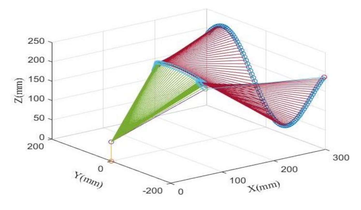
3.2. Simulation Results of the End Effector Positioning

In this section, simulation results based on the FSBSC system, in which the controller’s parameters are optimized by GWO-WWOA technique of the previous section are presented. The XYZ reference positions are given as x r = 300 mm , y r = 195 + 19.5 t mm , z r = 100 sin ( 0.016 ( y r + 150 ) ) + 120 mm . Figure 5 shows the trajectory of the end effector command position. For comparison with the proposed FSBSC system, the conventional BSC system was designed.
Simulation results for the Cartesian positioning command of the end-effector given in Figure 5 are presented in Figure 6. Figure 6a shows the 2D reference positioning command of the end effector. For the end effector positioning command shown in Figure 5 and Figure 6a, the joint position command was generated as shown in Figure 6b by the inverse kinematics. The positioning tracking results in the joint 1 are presented in Figure 6c,d, where the tracking error of the proposed FSBSC system is very small compared to that of the BSC system. The tracking outputs and errors are presented in Figure 6e–h, where the proposed FSBSC systems shows the results outperforming that of the BSC system.
Transforming the joint tracking results into that of the end-effector, the tracking output of the end-effector can be represented as shown in Figure 6i, where the better control performance of the proposed FSBSC system over the conventional BSC system is viewed as a 3D configuration. For the FSBSC system, ITAE values for each optimization technique are presented in Table 3, where the GWO-WWOA has the best performance over other three techniques.
In simulation, although a few control gains of the BSC system were twice as that of that of the FSBSC system, the control performance of the former system is poorer than the latter. Figure 6j,k present the control inputs of the BSC and FSBSC systems, where the level of the control input of the FSBSC system is lower than that of the BSC system owing to higher control gains of the BSC system. Therefore, the simulated results prove that the performance of the proposed FSBSC system is much enhanced compared to the conventional BSC system.

4. Conclusions

A bio-inspired GWO-WWO algorithm by a BSC systems with the IT2 fuzzy fractional-order finite-time sliding mode was designed for a MIMO nonlinear dynamic system. The following advantages were obtained in this study, namely: optimized control gains, improved control performance, a more compact backstepping controller design, and a robustness to uncertainty; these benefits were achieved by developing a fractional-order finite-time command filter, fractional-order sliding mode surface, and the GWO-WWOA technique. An IT2-FLS, which is more robust than the type 1 FLS, was introduced for the approximate estimation of unknown functions. Furthermore, the finite-time Lyapunov stability theorem proved the finite-time convergence of the closed-loop signals. The results of the comparative optimization and simulation, which were achieved using an articulated manipulator, showed the improvement and efficacy of the proposed method over the existing GWO, WOA, and BSC systems.
Therefore, the first distinct method studied in this paper comparing with the conventional methods is the enhanced fractional-order sliding surface with the novel fractional-order command filter. These signals provided more advanced robustness to uncertainties than the conventional sliding mode surface and command filter, which are constructed based on integer-order calculus. Next, the fractional-order backstepping control strategy can provide more rapid convergence and advanced robustness comparing with the conventional backstepping control scheme. Finally, more enhanced optimization performance via the GWO-WWOA method can be obtained comparing with the conventional optimization methods. All control parameters are optimized via the proposed GWO-WWOA method.
Future works could be to develop the implementation of the experimental optimization of the GWO-WWOA technique and design of the state observer-based controller to enhance the availability of the proposed control scheme.

Funding

This work was funded by the National Research Foundation of Korea(NRF) grant funded by the Korea government (MSIT) (No. NRF-2018R1A2B6005128) and was funded by the Dongguk University Research Fund of 2019.

Institutional Review Board Statement

Not applicable.

Informed Consent Statement

Informed consent was obtained from all subjects involved in the study.

Data Availability Statement

The data presented in this study are available on request from the corresponding author.

Acknowledgments

This work was supported by the National Research Foundation of Korea(NRF) grant funded by the Korea government (MSIT) (No. NRF-2018R1A2B6005128) and was supported by the Dongguk University Research Fund of 2019.

Conflicts of Interest

The author declares no conflict of interest.

Abbreviation

BSC, FLS, DSCbackstepping control, fuzzy logic system, dynamic surface control
SMC, IT2sliding mode control, interval type-2
ACO, PSOant colony optimization, particle swarm optimization
GWO,WOAgrey wolf optimization, whale optimization algorithm
WWOAweighted whale optimization algorithm
ITAEintegral time absolute error
FSBSCfractional-order sliding mode backstepping control
β ,    γ fractional-order constants
Θ ,    ε approximated function, approximation error
e ,    η    tracking error, command filtering error
ξ ,    α    command filter state varibale, virtual control input
x , s state variable, sliding mode surface
l , d , ρ uncertainty, external disturbance, lumped disturbance
c 1 , c 2 , c 3 , c 4 gains of command filter
λ 1 , λ 2 gains of sliding mode surface

References

  1. Kristic, M.; Kanellakopoulos, I.; Kokotovic, P.V. Nonlinear and Adaptive Control Design; Wiley: New York, NY, USA, 1995. [Google Scholar]
  2. Fang, Y.; Fei, J.; Yang, Y. Adaptive backstepping desoign of a microgyroscope. Micromachines 2018, 9, 338. [Google Scholar] [CrossRef] [PubMed] [Green Version]
  3. Li, X.; Zhu, Z.C.; Rui, G.C.; Cheng, D.; Shen, G.; Tang, Y. Force loading tracking control of an electro-hydraulic actuator based on a nonlinear adaptive fuzzy backstepping control scheme. Symmetry 2018, 10, 155. [Google Scholar] [CrossRef] [Green Version]
  4. Tran, D.T.; Nguyen, M.N.; Ahn, K.K. RBF neural network based backstepping control for an eletrcohydraulic elastic manipulator. Appl. Sci. 2019, 9, 2237. [Google Scholar] [CrossRef] [Green Version]
  5. Lin, C.H. A rectified reiterative sieved-pollaczek polynomials neural network backstepping control with improved fish school search for motor drive system. Mathematics 2020, 8, 1699. [Google Scholar] [CrossRef]
  6. Swaroop, S.; Hedrick, J.K.; Yip, P.P.; Gerdes, J.C. Dynamic surface control for a class of nonlinear systems. IEEE Trans. Autom. Control 2000, 45, 1893–1899. [Google Scholar] [CrossRef] [Green Version]
  7. Han, S.I. Partial tracking error constrained fuzzy dynamic surface control for a strict feedback nonlinear dynamic system. IEEE Trans. Fuzzy Syst. 2014, 22, 1049–1061. [Google Scholar] [CrossRef]
  8. Guo, Q.; Liu, Y.; Jiang, D.; Wang, Q.; Xiong, W.; Liu, J.; Li, X. Prescribed performance constraint regulation of electrohydraulic control based on backstepping with dynamic surface. Appl. Sci. 2018, 8, 76. [Google Scholar] [CrossRef] [Green Version]
  9. Ma, H.; Liang, H.; Zhou, Q.; Ahn, C.K. Adaptive neural network dynamic surface control of strict-feedback nonlinear systems with full state constraints and unmodeled dynamics. IEEE Trans. Syst. Man Cyber Syst. 2019, 49, 506–515. [Google Scholar] [CrossRef]
  10. Li, Y.; Li, K.; Tong, S. Finite-time adaptive fuzzy output feedback dynamic surface control for MIMO nonstrict feedback systems. IEEE Trans. Fuzzy Syst. 2019, 27, 96–110. [Google Scholar] [CrossRef]
  11. Yu, J.; Shi, P.; Zhao, L. Finite-time command filter backstepping control for a class of nonlinear systems. Automatica 2018, 92, 173–180. [Google Scholar] [CrossRef]
  12. Zhang, J.; Xia, J.; Sun, W.; Wang, Z.; Shen, H. Command filter-based finite-time adaptive fuzzy control for nonlinear systems with uncertain disturbance. J. Frankl. Inst. 2019, 356, 11270–11284. [Google Scholar] [CrossRef]
  13. Podlubny, I. Fractional Differential Equations; Academic Press: New York, NY, USA, 1999. [Google Scholar]
  14. Ma, C.; Hori, Y. Fractional-order control: Theory and applications in motion control [Past and Present]. IEEE Ind. Electron. Mag. 2007, 1, 6–16. [Google Scholar] [CrossRef]
  15. Padula, F.; Visioli, A. Tuning rules for optimal PID and fractional-order PID controllers. J. Process. Control 2011, 21, 69–81. [Google Scholar] [CrossRef]
  16. Bandyopadhyay, B.; Kamal, S. Stabilization and Control of Fractional Order Systems: A Sliding Mode Approach; Springer: Berlin/Heidelberg, Germany, 2015; Volume 317. [Google Scholar]
  17. Aghababa, M.P. Design of a chatter-free terminal sliding mode controller for nonlinear fractional-order dynamical system. Int. J. Control 2013, 86, 1744–1756. [Google Scholar] [CrossRef]
  18. Yaoyao, W.; Surong, J.; Bai, C.; Hongtao, W. A new continuous fractional-order nonsingular terminal sliding mode control for cable-driven manipulator. Adv. Eng. Softw. 2018, 119, 21–29. [Google Scholar]
  19. Gong, P.; Lan, W. Adaptive robust tracking control for multiple unknown fractional-order nonlinear systems. IEEE Trans. Cybern. 2019, 49, 1365–1376. [Google Scholar] [CrossRef] [PubMed]
  20. Slotine, J.J.; Li, W. Applied Nonlinear Control; Prentice-Hall: New York, NY, USA, 1991. [Google Scholar]
  21. Lin, C.Y.; Jheng, H.W. Active vibration suppression of a motor-driven piezoelectric smart structure using adaptive fuzzy sliding mode control and repetitive control. Appl. Sci. 2017, 7, 240. [Google Scholar] [CrossRef] [Green Version]
  22. Zhao, W.; Song, A.; Cao, Y. An extended proxy-based sliding mode control of pneumatic muscle actuators. Appl. Sci. 2019, 9, 1571. [Google Scholar] [CrossRef] [Green Version]
  23. Mendal, J.M.; John, R.I.; Liu, F. Interval type-2 fuzzy logic systems made simple. IEEE Trans. Fuzzy Syst. 2006, 14, 808–821. [Google Scholar] [CrossRef] [Green Version]
  24. Mohadeszadeh, M.; Helavari, H. Synchronization of uncertain fractional-order hyperchaotic systems via a novel adaptive interval type-2 fuzzy active sliding mode controller. Int. J. Dyn. Control 2017, 5, 135–144. [Google Scholar] [CrossRef]
  25. Sun, X.; Zhang, Q. Admissibility analysis for interval type-2 fuzzy descriptor systems based on sliding mode control. IEEE Trans. Cybern. 2019, 49, 3032–3040. [Google Scholar] [CrossRef] [PubMed]
  26. Bernal, E.; Castillo, O.; Soria, J.; Valdez, F. Optimization of fuzzy controller using galactic swarm optimization with type-2 fuzzy dynamic parameter adjustment. Axioms 2019, 8, 26. [Google Scholar] [CrossRef] [Green Version]
  27. Li, P.; Zhang, D.; Hu, J.; Lennox, B.; Arvin, F. Hysteresis modelling and feedforward control of piezoelectric actuator based on simlified interval type-2 fuzzy system. Sensors 2020, 20, 2587. [Google Scholar] [CrossRef]
  28. Hosseinzadeh, M.; Sadati, N.; Zamani, I. H disturbance attenuation of fuzzy large-scale systems. In Proceedings of the 2011 IEEE International Conference on Fuzzy Systems, Taipei, Taiwan, 27–30 June 2011; pp. 2364–2368. [Google Scholar]
  29. Liang, Z.; Li, Y.; Xu, L. Grain sieve loss fuzzy control system in rice combine harvesters. Appl. Sci. 2019, 9, 114. [Google Scholar] [CrossRef] [Green Version]
  30. Dorigo, M.; Blum, C. Ant colony optimization: A survey. Theor. Comput. Sci. 2005, 344, 243–278. [Google Scholar] [CrossRef]
  31. Poli, R.; Kennedy, J.; Blackwell, T. Particle swarm optimization: An overview. Swarm Intell. 2007, 1, 33–57. [Google Scholar] [CrossRef]
  32. Mirjalili, S.; Mirjalili, S.M.; Lewis, A. Grey wolf optimizer. Adv. Eng. Softw. 2014, 69, 46–61. [Google Scholar] [CrossRef] [Green Version]
  33. Oliveira, J.; Oliveira, P.M.; Boaventura-Cunha, J.; Pinho, T. Chaos-based grey wolf optimizer for higher order sliding mode position control of a robotic manipulator. Nonlinear Dyn. 2017, 90, 1353–1362. [Google Scholar] [CrossRef]
  34. Obadina, O.O.; Thaha, M.; Althoefer, K.; Shaheed, M.H. A modified computed torque control approach for a master-slave robot manipulator system. In Proceedings of the Annual Conference Towards Automation Robotic Systems, Bristol, UK, 25–27 July 2018; pp. 28–39. [Google Scholar]
  35. Zhou, Z.; Wang, C.; Zhu, Z.; Wang, Y.; Yang, D. Sliding mode control based on a hybrid grey-wolf-optimized extreme earning machine for robot manipulators. Int. J. Light Electron. Opt. 2019, 185, 364–380. [Google Scholar] [CrossRef]
  36. Mirjalili, S.; Lewis, A. The whale optimization algorithm. Adv. Eng. Softw. 2016, 95, 51–67. [Google Scholar] [CrossRef]
  37. Ghahremani-Nahr, J.; Kian, R.; Sabet, E. A robust fuzzy methematical programming model for the closed-loop suppy chain network design and a whale optimization solution algorithm. Expert Syst. Appl. 2019, 116, 454–471. [Google Scholar] [CrossRef] [Green Version]
  38. Liu, Y.; Wang, W.; Tong, S.; Liu, Y. Robust adaptive tracking control for nonlinear systems based on bounds of fuzzy approximation parameters. IEEE Trans. Fuzzy Syst. 2010, 40, 170–184. [Google Scholar] [CrossRef]
  39. Wu, D.; Mendel, J.M. Enhanced Karnik-Mendel algorithms. IEEE Trans. Fuzzy Syst. 2009, 17, 923–934. [Google Scholar]
  40. Wang, L. Adaptive Fuzzy Systems and Control: Design and Stablility Analysis; Prentice-Hall: Englewood Cliffs, NJ, USA, 1994. [Google Scholar]
  41. Levant, A. Robust exact differentiation via sliding mode technique. Automatica 1998, 34, 379–384. [Google Scholar] [CrossRef]
  42. Levant, A. Higher-order sliding modes, differentiation and output- feedback control. Int. J. Control 2003, 76, 924–941. [Google Scholar] [CrossRef]
  43. Moreno, J.A.; Osorio, M. A Lyapunov approach to second-order sliding mode controllers and observers. In Proceedings of the 47th IEEE Conference on Decision and Control, Cancun, Mexico, 9–11 December 2008; pp. 2856–2861. [Google Scholar]
Figure 1. (a) Schematic diagram of IT2-FLS. (b) IT2-fuzzy Gaussian MF.
Applsci 11 00489 g001
Figure 2. Command filtering error for the sine wave input.
Applsci 11 00489 g002
Figure 3. The configuration of the self-designed articulated manipulator system.
Applsci 11 00489 g003
Figure 4. The ITAE values for each joint obtained from WOA, GWO, and GWO-WOA, and WWOA techniques. (a) link 1. (b) link 2. (c) link 3.
Applsci 11 00489 g004
Figure 5. The trajectory of the end-effector command position.
Applsci 11 00489 g005
Figure 6. The end effector positioning tracking results. (a) Reference positioning command of the end effector in the Cartesian coordinate. (b) Reference positioning command of the end effector in the joint coordinate. (c) Command tracking output in the joint 1 of the BSC and the FSBSC systems. (d) Command tracking error in the joint 1 of the BSC and the FSBSC systems (e) Command tracking output in the joint 2 of the BSC and the FSBSC systems. (f) Command tracking error in the joint 2 of the BSC and the FSBSC systems. (g) Command tracking output in the link 3 the BSC and the FSBSC systems. (h) Command tracking error in the link 3 the BSC and the FSBSC systems. (i) 3D tracking trajectory of the end effector of the BSC and the FBSC systems. (j) Control input of the BSC system. (k) Control input of the FSBSC system.
Applsci 11 00489 g006aApplsci 11 00489 g006bApplsci 11 00489 g006c
Table 1. Optimized values of the parameters of the controller via GWO-WWOA.
JointOptimized Values
Joint 1 γ 1 , 1 , 1 = 0.19 ,    γ 1 , 1 , 2 = 0.73 ,    γ 1 , 2 , 1 = 0.05 ,    γ 1 , 2 , 2 = 0.74 ,    λ 1 , 1 , 1 = 0.09 ,    λ 1 , 1 , 2 = 0.15 , c 1 , 1 = 2 , c 1 , 2 = 2 , c 1 , 3 = 1.0 , c 1 , 4 = 1.0 , k 1 , 1 , 1 = 1 , k 12 = 0.9 , υ 1 , 1 = 0.001
Joint 2 γ 2 , 1 , 1 = 0.2 ,    γ 2 , 1 , 2 = 0.7 ,    γ 2 , 2 , 1 = 0.19 ,    γ 2 , 2 , 2 = 0.86 ,    λ 2 , 1 , 1 = 0.29 ,    λ 2 , 1 , 2 = 0.25 , c 2 , 1 = 2 , c 2 , 2 = 2 , c 2 , 3 = 0.96 , c 2 , 4 = 0.51 , k 2 , 1 , 1 = 5.2 , k 22 = 5.6 , υ 2 , 1 = 0.001
Joint 3 γ 3 , 1 , 1 = 0.2 ,    γ 3 , 1 , 2 = 0.71 ,    γ 3 , 2 , 1 = 0.14 ,    γ 3 , 2 , 2 = 0.80 ,    λ 3 , 1 , 1 = 0.07 ,    λ 3 , 1 , 2 = 0.53 , c 3 , 1 = 2 , c 3 , 2 = 2 , c 3 , 3 = 1.4 , c 3 , 4 = 1.6 , k 3 , 1 , 1 = 2.7 , k 32 = 2.2 , υ 3 , 1 = 0.001
Table 2. Optimized values of the parameters of IT2-FLS via GWO-WWOA.
JointOptimized Values of Each Parameter
Joint 1 m 11 = 1.9 ,    m 12 = 0.4 , m 13 = 0 ,     m 14 = 0.4 ,    m 15 = 0.98 m 21 = 1.9 ,    m 22 = 0.9 , m 23 = 0 ,     m 24 = 0.41 , m 25 = 0.95 σ 11 = 0.58 ,    σ 12 = 0.49 , σ 13 = 0.62 , σ 14 = 0.49 , σ 15 = 0.59 , σ 21 = 0.47 ,    σ 22 = 0.45 , σ 13 = 0.49 , σ 14 = 0.61 , σ 15 = 0.48 , Δ m 1 = 0.014 ,    Δ m 2 = 0.05
Joint 2 m 11 = 0.9 ,    m 12 = 0.4 , m 13 = 0 ,     m 14 = 0.4 ,    m 15 = 1 m 21 = 0.9 ,    m 22 = 0.5 , m 23 = 0 ,     m 24 = 0.4 ,    m 25 = 0.9 σ 11 = 0.63 ,    σ 12 = 0.62 , σ 13 = 0.45 , σ 14 = 0.64 , σ 15 = 0.54 , σ 21 = 0.54 ,    σ 22 = 0.52 , σ 13 = 0.47 , σ 14 = 0.51 , σ 15 = 0.5 , Δ m 1 = 0.02 ,    Δ m 2 = 0.02
Joint 3 m 11 = 1.9 ,    m 12 = 0.9 , m 13 = 0 ,     m 14 = 0.47 ,    m 15 = 0.90 m 21 = 1.9 ,    m 22 = 0.9 , m 23 = 0 ,     m 24 = 0.40 ,    m 25 = 1.0 σ 11 = 0.45 ,    σ 12 = 0.51 , σ 13 = 0.45 , σ 14 = 0.65 , σ 15 = 0.47 , σ 21 = 0.61 ,    σ 22 = 0.65 , σ 13 = 0.45 , σ 14 = 0.64 , σ 15 = 0.48 , Δ m 1 = 0.01 ,    Δ m 2 = 0.01
Table 3. ITAE value of WOA, GWO, GWO-WOA-WWOA technique at iteration 30.
TechniqueJoint 1Joint 2Joint 3
WOA0.035 (100%)0.0063 (100%)0.020 (100%)
GWO0.025 (71%)0.0029 (46%)0.018 (90%)
GWO-WOA0.020 (57%)0.0028 (44%)0.017 (85%)
GWO-WWOA0.017 (49%)0.25 (40%)0.011 (55%)
Publisher’s Note: MDPI stays neutral with regard to jurisdictional claims in published maps and institutional affiliations.

