Abstract
In this study, eight configurations of oval and flat tubes in annular finned-tube thermal devices are examined and compared with the conventional circular tube. The objective is to assess the effect of tube flatness and axis ratio of the oval tube on thermal-flow characteristics of a three-row staggered bank for Re (2600 ≤ Re ≤ 10,200). It has been observed that the thermal exchange rate and Colburn factor increase according to the axis ratio and the flatness, where O1 and F1 provide the highest values. O1 produces the lowest friction factor values of all the oval tubes at all Re, and F4 gives 13.2–18.5% less friction than the other tube forms. In terms of performance evaluation criterion, all of the tested tubes outperformed the conventional circular tube (O5), with O1 and F1 obtaining the highest values. The global performance criterion of O1 has been found to be 9.6–45.9% higher as compared to the other oval tube geometries at lower values of Re, and the global performance criterion increases with the increase in flatness. The F1 tube shape outperforms all the examined tube designs; thus, this tube geometry suggests that it be used in energy systems.
Keywords:
heat exchanger; tube shapes; flat tube; oval tube; annular fin; thermal-hydraulics; CFD simulation 1. Introduction
Independent finned-tube heat exchangers (FTHEs) are widely utilized in heat generation systems, such as cryogenics [1], air conditioning [2], radiators of automobiles [3], aerospace [4], and nuclear power stations [5]. The intent of FTHEs is to dissipate the heat generated to the external environment to improve the efficiency of the engineering systems. Generally, the large thermal resistance of FTHEs is yielded by the air-side due to the thermo-physical property of air [6,7]. The energy efficiency on the gas side of the independent FTHEs may be increased by changing the tube and fin shapes [8,9,10,11,12]. Furthermore, the fluid recirculation in the thermally dead zones and the pressure drop due to the drag force are widely affected by the tube shape [13,14,15,16]. For that, numerous studies have been performed to enhance the thermohydraulic characteristics on the air-side of thermal devices by designing and comparing the performance of different tube geometry [17,18,19].
For flat tubes, several researchers analyzed the effect of flat tube dimensions and compared their thermal flow characteristics with the conventional circular tubes. Fiebig et al. [20] compared the hydrothermal details for a staggered three-row bundle with circular and flat tubes using the liquid crystal thermography method. For a Re range of (600–3000), they reported that the longitudinal vortices yield a significant thermal enhancement for flat tubes (100%), but only a marginal increase in the thermal exchange (10%) for circular tubes. However, the pressure drop of the conventional circular tubes is twice that in flat tubes. The naphthalene sublimation technique was employed by Seong et al. [21] to calculate the local thermal exchange coefficients of plain FTHEs with and without vortex generators and for circular and flat tubes. For the case of thermal devices with VGs, the flat tubes provide significant thermal exchange compared to the conventional circular-shaped tubes. Moreover, in the case of thermal devices without VGs, the convective thermal exchange coefficient of fin flat-tubes is lower than those of FTHEs with circular tubes.
Both experiment and numerical simulations were conducted by Du et al. [22] to study the thermohydraulic details of wavy fin-and-flat tube thermal exchangers with longitudinal delta winglet vortex generators. Compared with the traditional smooth wavy fin-and-flat-tube, the Nusselt number increased by 21% to 60% for a Re range of (1500–4500). However, for a range of Re of (500–4500), the friction factor increased by 13% to 83%. For a one-row annular fin-and flat-tube, Zaidan et al. [23] compared the turbulent hydrothermal characteristics of non-perforated annular fins and various perforation shapes of annular fins (circular, square, and triangular perforation shapes).
Recently, Unger et al. [24] numerically investigated the impact of tube bundle arrangement, flat-tube dimensions, transverse, and longitudinal tube pitches on natural convection thermal exchange. They observed that the circular tube and flat-shaped tube with an axis ratio of 1:2.1 were the most efficient configurations. Darbari and Alavi [25] applied the Taguchi method to explore the impact of flat tube configurations (without fins). Alnakeeb et al. [26] conducted numerical simulations to investigate the thermal and hydraulic details of a plain plate-fin with varying inlet air velocity and flat-tube aspect ratio . The simulation results indicate that reducing the aspect ratio of the flat tube from 1 to 0.33 lowered the pressure loss by 33.7% (at ) and 57.3% (at ). On the other hand, the thermal exchange increased by 52.9% (at ) and 111.5% (at ).
Next to the flat-shaped tubes, the oval or elliptic tube configuration has a major role in the thermal exchange performance of a FTHE. Jang and Yang [27] achieved experiments and simulations on annular-finned tubes under wet and dry conditions. They found that the thermal exchange coefficient was higher by 50% for elliptical finned-tubes than that for circular finned-tubes. Saboya and Saboya [28] performed experiments in one- and two-row plate-fin and oval-tube HEs to determine the heat transfer characteristics in the range of Re of (150–1300). They illustrated that replacing the conventional circular tube with an oval one substantially reduces the pressure losses and increases the fin efficiency; however, there was no major difference in the average thermal exchange coefficients between these two tube shapes. Leu et al. [29] and Liu et al. [30] investigated a louver fin having circular and oval tube patterns. They found a decrease in thermal exchange and pressure loss for the case of oval tubes. Erek et al. [31] reported in their study that the thermal exchange increases and the pressure loss decreases with increasing tube ellipticity.
VGs (vortex generators) may be employed to provide strong heat transfer processes that include interrupting the growth of boundary layer, formation of horseshoe vortices, and flow mixing. For a plate FTHE, Lin et al. [32], Tiwari et al. [33], and O’Brien et al. [34] analyzed the effects of adding VGs in conjunction with the oval tube. They observed a significant hydrothermal enhancement by using this technique.
Ibrahim et al. [35] studied five samples of oval THE, and they optimized the axis ratio (1:4, 1:3, 1:2, and 1:1) and flow angle of attack () for a range of . In addition, a combined investigation consisting of CFD simulations and genetic algorithms was performed by Sun and Zhang [36] to inspect the impact of tube rows, transversal and longitudinal tube pitch, air velocity, and fin spacing on the efficiency of elliptical plate FTHEs for a range of . In contrast to previous researching works, they considered the thermal and fluid flow characteristics in a staggered two-row bundle. Their outcomes reveal that at higher air velocity or lower water flow rate, increasing the axis ratio increases the hydrothermal efficiency, whereas at lower airspeed or higher water flow, the reverse effect occurs. Similarly, Sun et al. [37] compared refrigerant-to-air finned-tube condensers with circular and oval tubes by using numerical simulations. According to the researchers, using elliptical tubes increased the coefficient of performance (COP) by 3.6–6.7%. Kumar et al. [38] investigated the impact of row numbers (2–10), tube geometry (oval and circular), and other parameters on the efficiency of the annular finned-tube bundle. They claimed that elliptical tubes with the lowest ellipticity (0.33) perform better than other tube shapes. Zeeshan et al. [39] evaluated the performance of plate FTHE using circular, oval, and flat tube shapes for seven rows with staggered or in-line tube banks. The overall performance of the cross-flow heat exchanger can be improved by reducing the flatness of a flat tube and the axis ratio of an oval tube. Moreover, based on the considered three performance evaluation criteria, they concluded that the oval geometry with the highest axis ratio is the optimum tube shape.
Recently, the impact of tube geometry on thermal and mass transfer was experimentally and numerically investigated by He et al. [40]. The convective thermal exchange coefficient of an oval tube is approximately 66% higher than that of a circular tube, and the dehumidifying coefficient is approximately 21% higher. Matos et al. [41] evaluated the gain in energy efficiency owing to the use of oval tubes rather than circular tubes in the evaporator of a conditioning system. They reported that the optimized oval-tube outperforms the conventional circular-tube shape by approximately 13% and 15% in heat transfer rates, 9% and 13.5% in coefficients of performance (COP), and 13% and 16.6% in heat transfer coefficients for Re = 1030 and 2060, respectively. Moreover, other investigations by numerical and experimental treatments have been carried out by Sakhri et al. [42,43,44], Chamkha et al. [45], Boursas et al. [46], Chekchek et al. [47], Hadidi et al. [48], Menni et al. [49,50,51,52], Ahmad et al. [53], Salmi et al. [54], Ameur et al. [55], Mahammedi et al. [56], Maouedj et al. [57], etc. Their studies suggested different models of heat exchangers in order to improve the performance under various limit conditions.
As seen from the aforementioned research works, several researchers have studied, separately, the effect of the axis ratio of oval tubes and the flatness of flat tubes in cross-flow FTHEs. However, only one numerical investigation was conducted by Zeeshan et al. [39] to compare the air-side thermal-hydraulic performance of plate FTHEs using circular, oval, and flat tube shapes, whereas no study was performed on the impact of these tube shapes for the case of annular fins. Therefore, in the present work, special attention is paid to the annular fins with circular, oval, and flat tube configurations. The numerical results have been obtained having three-row staggered banks for a range of Re (2600 ≤ Re ≤ 10,200).
2. Problem Description
2.1. Geometry
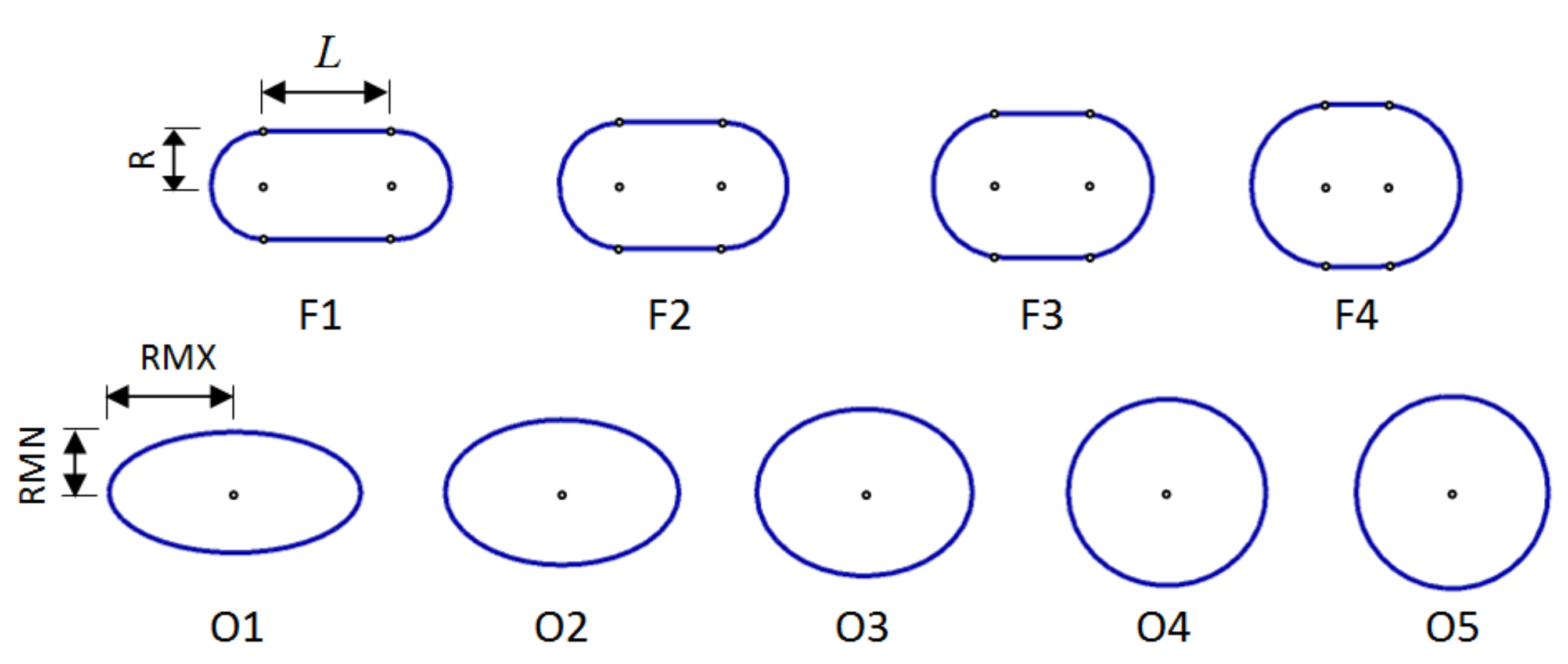
Figure 1 depicts the proposed three-row staggered FTHEs with flat tubes layout. Cold air flows around the annular -inned tube while hot fluid flows inside the tubes. The air-side thermal exchange rate and pressure loss are evaluated in cross-flow thermal devices for three configurations of tubes: oval shape, circular shape, and flat shape. Four distinct shapes of each flat and oval tube were compared with the conventional circular tube. The variation in the hydraulic diameters of both oval and flat-shaped tubes has been chosen based on the numerical study of Zeeshan et al. [39] (Figure 2). Stainless steel (Aisi 304) was used for the solid body, including the annular fins, with a thermal conductivity of . The values of the basic parameters of the present annular fins are listed in Table 1.
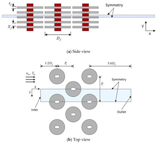
Figure 1.
Scheme representing the geometrical parameters of the investigated annular fins with a flat tube.
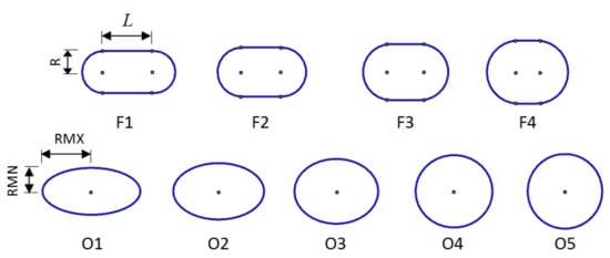
Figure 2.
Schematic of different flat and oval tube geometries (RMN = minor axis radius, RMX = major axis radius).

Table 1.
Annular fins and tube shape dimensions.
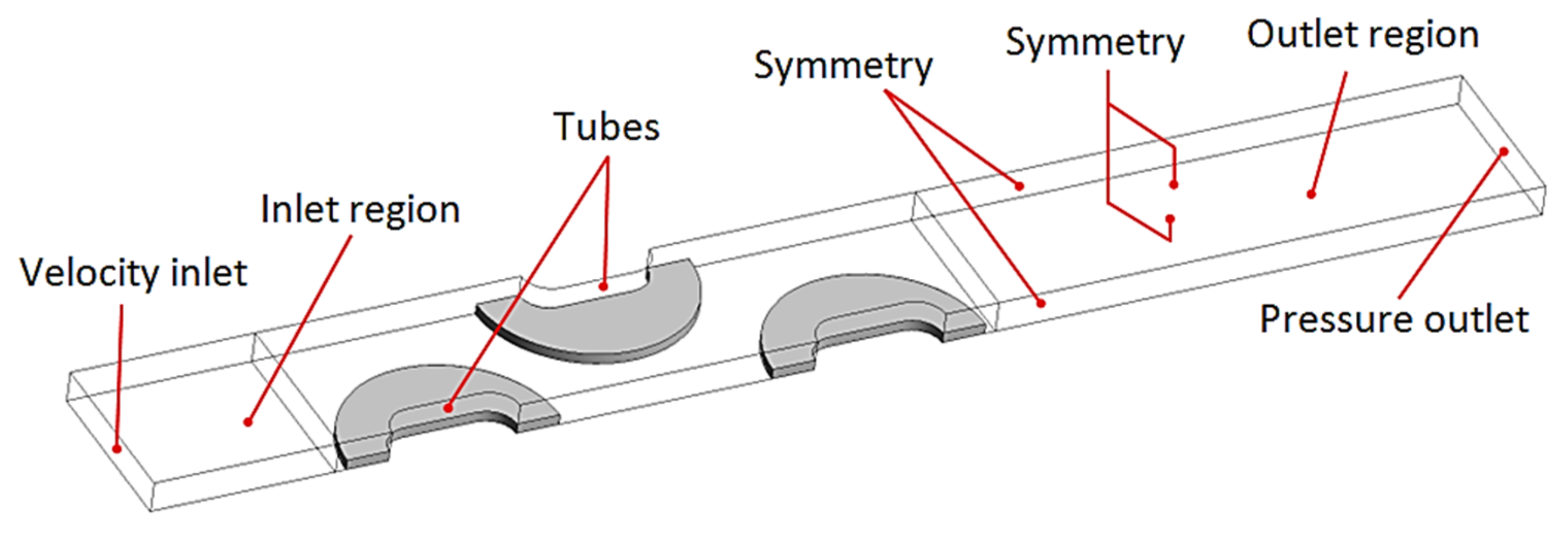
In this research work, we investigated and compared nine geometries of annular finned-tube heat exchangers. Figure 3 reveals the 3D-computational domain, its size, and all boundary conditions selected for the simulation. In order to keep the computational domain as small as possible and to speed up the computation time, the symmetrical boundary is chosen for the four lateral boundaries of the computational domain. No-slip coupled walls are used at solid-fluid interfaces, including tube outer surfaces and annular fin surfaces.
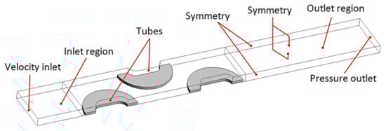
Figure 3.
3-D Computational domain.
The present computational domain is extended by 1.2-times the fin diameter, from the center of first row, and the outlet region extended by 3.6-times the fin diameter, from the center of the last row, to ensure a uniform inlet velocity and to avoid the reverser flow at the outlet.
2.2. Mathematical Details
2.2.1. Governing Equations
In the present investigation, the Reynolds number, which is based on the hydraulic diameter of the heat exchanger (Dh) and the maximum velocity in the domain, range from 2600 to 10,200. As a result, incompressible, three-dimensional, steady-state, and turbulent air flow is assumed [23,58]. For this problem, the 3-D governing equations of continuity and the momentum (RANS equations) and energy equations may be written in Cartesian coordinates as follows:
where:
According to previous numerical studies, for annular FTHEs [23,38,58,59], the RNG turbulence model of Ansys 18.2 is used in this investigation. The transport equations of this turbulence model can be expressed in the following equations:
and are the turbulent kinetic energy and the dissipation rate of , respectively. The quantities and represent, respectively, the inverse of Prandtl numbers for and . For more details of RNG theory see Ref. [60].
Energy equation:
where, is the total energy and is the turbulent thermal conductivity.
In the solid region, including annular fins, the energy transport equation is represented as:
2.2.2. Boundary Conditions
The actual numerical problem is solved as conjugated conduction–convection thermal exchange, and the conduction through the annular fins is analyzed. The details concerning the boundary conditions, shown in Figure 3, are given in Table 2.
Table 2.
Boundary conditions.
3. Numerical Treatment
3.1. Numerical Model
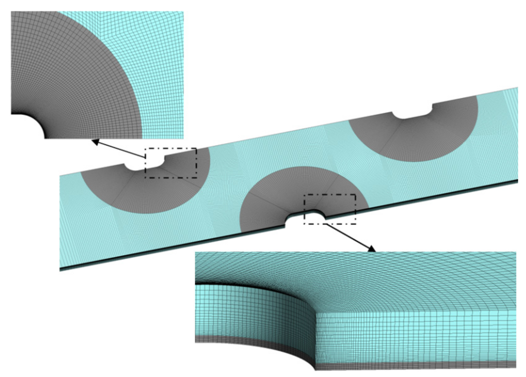
In this numerical investigation, the commercial software ANSYS FLUENT 18.2 was utilized. As shown in Figure 4, the mesh layers are refined in regions where the gradients of velocity and temperature are high, such as surrounding the flat and oval tubes, as well as annular-fin surfaces. The choice of the first grid corresponds to the requirement of the y+ parameter of the renormalization group of the k-ε turbulence model (y+ ≤ 5.0).
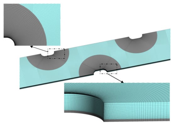
Figure 4.
Grid structure used in simulations.
To obtain a grid-independent solution, the preliminary simulations were run with various grid densities for the case of tube shape F4, under the value of Re = 10,032, as illustrated in Table 3. Based on the results presented in this table, the mesh of 1.1 million hexahedral cells was applied in the present numerical analyses.
Table 3.
Grid independence test.
3.2. Definition of Parameters
The air-side thermal exchange rate of annular fins with flat and oval tubes is evaluated as follows:
where, .
The convective thermal exchange coefficient over the finned-tube surface may be determined as:
with the logarithmic mean temperature difference:
where, is the total annular fin surface area, is the total tube surface area, and is the annular fin efficiency. The annular fin efficiency is given by the formula used in Refs. [61,62] as:
The air temperature is the average temperature of the ambient air calculated from both the inlet and outlet region of the computational domain, and is the tube base temperature.
The following dimensionless parameters were utilized to determine the hydrothermal details:
Here, is the flow length.
For the best selection of tube shape with annular fins, it is important to calculate the Colburn J and f friction factors; therefore, we used the performance evaluation criterion Pec defined in Refs. [35,38,39] as follows:
To take into account the influence of tube patterns on the thermo-hydraulic efficiency of the cross-flow thermal device, we used the global performance criterion Gpc, which is defined in Refs. [39,62] as follows:
where, is the volumetric flow rate and is the total air-side heat transfer rate.
3.3. Validation
The validation has already been carried out in our previous work. The thermal exchange rate, average thermal exchange coefficient, and pressure loss are the parameters used in the validation under various inlet flow velocity values. In our numerical study [63], the validation of some predicted findings against the experimental data in the open literature is carried out for a single circular tube with annular fins with a diameter of 99 mm. However, in the experimental and 3D numerical investigation of our published work [59], the result validation was conducted for a four-row annular finned-tube bundle.
4. Findings and Analysis
4.1. Impact of Tube Shape on Flow Pattern and Local Temperature Distribution
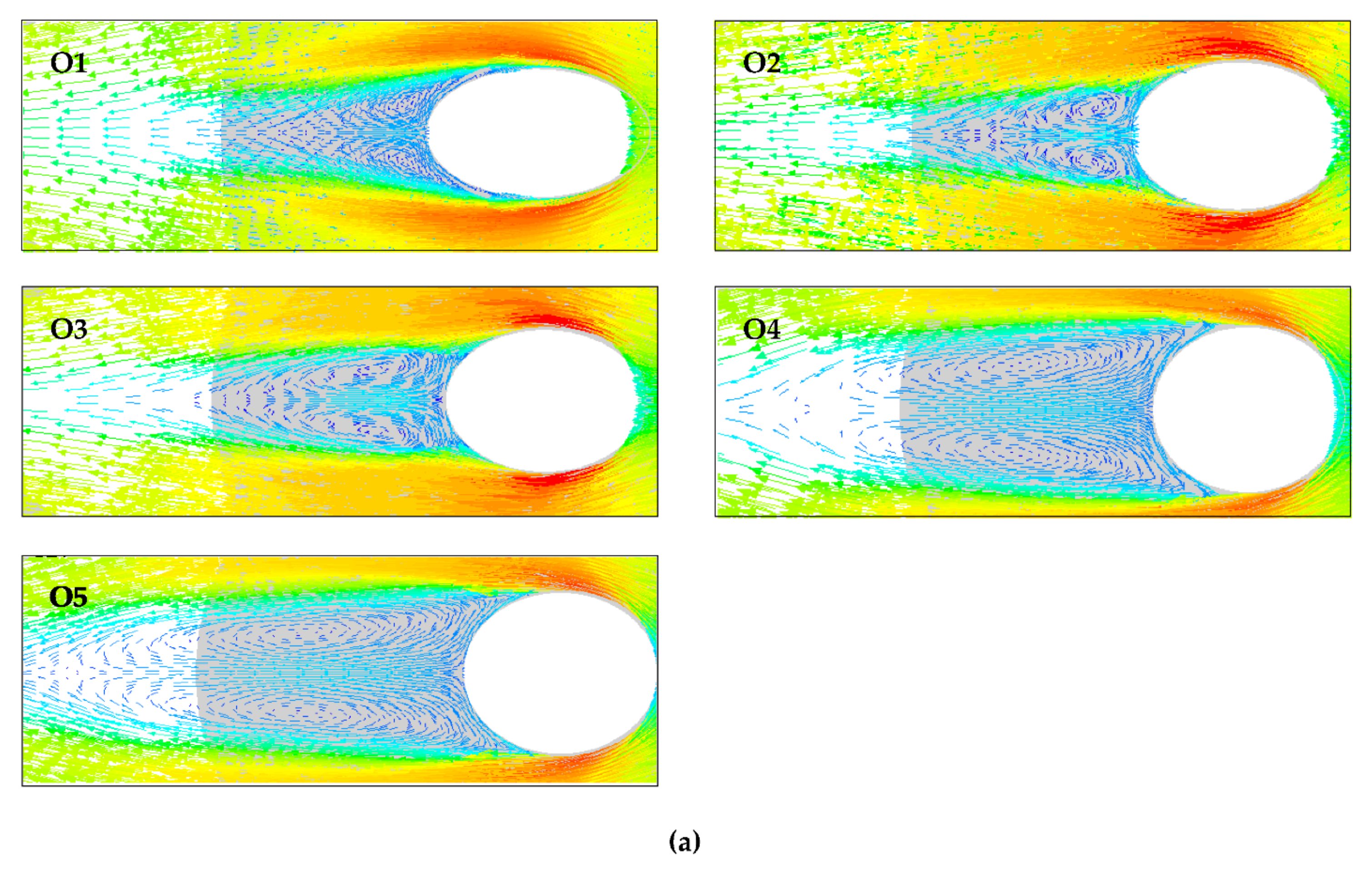
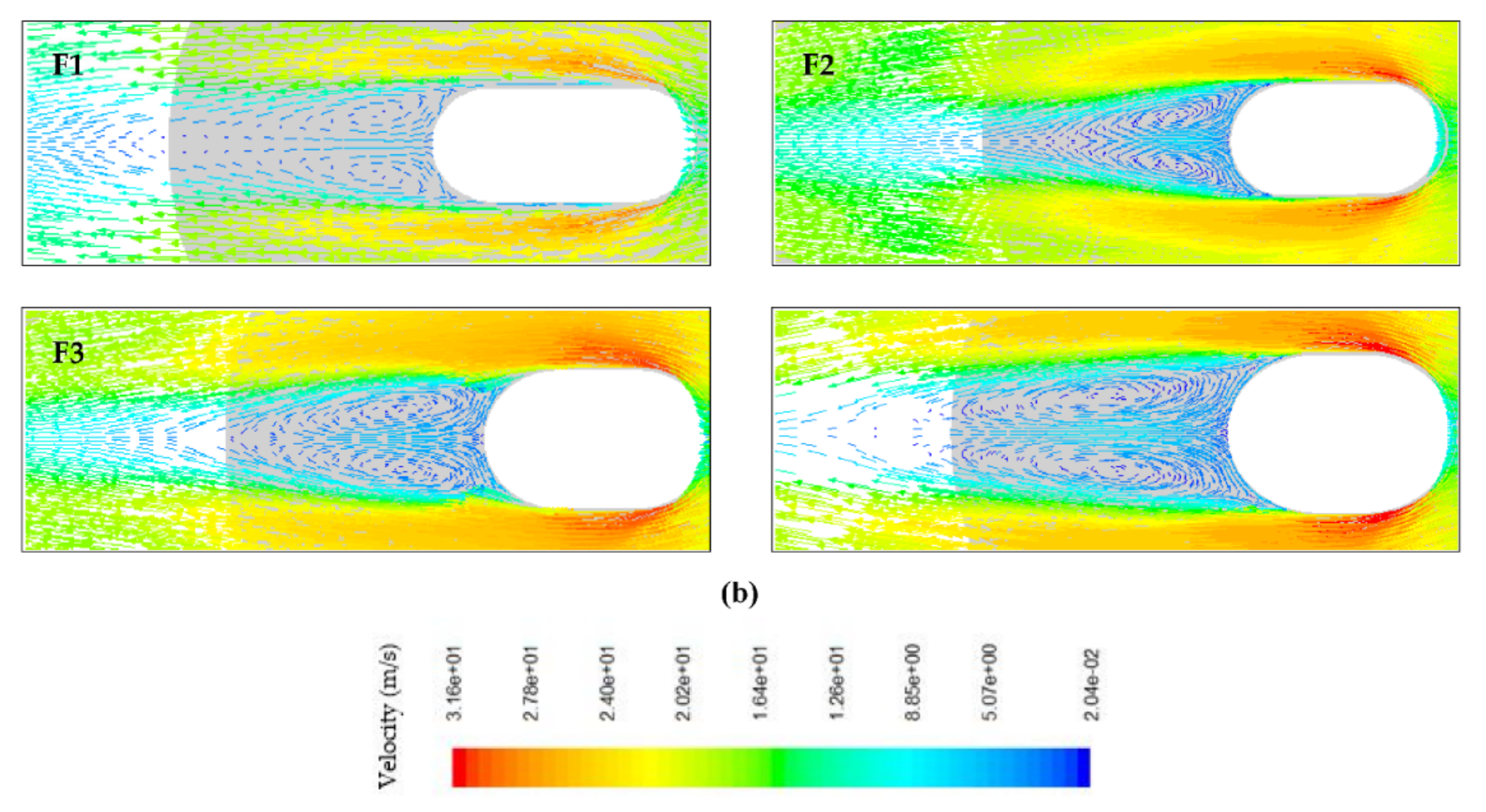
Finding the tube geometry that reduces the inactive heat transfer region (recirculation zone) and improves the heat transfer intensity is very important [7]. The velocity vectors near the fins and behind the tubes of the second rows for both oval and flat tube configurations are illustrated, respectively, in Figure 5a,b, at the maximum inlet velocity. For all tube designs, the recirculating vortices may be seen starting from the flow separation point, moving alongside the mean flow, and then returning to touch the rear wall of the tube (dotted circles). However, the size of this recirculation clearly decreases with the increase of ellipticity and flatness of tubes where the size of the wake region shrinks for O1 and F1 tube shapes. For all cases, the maximum fluid velocity is always found at the narrowest cross-section flow passage between two adjacent tubes; because of this, the right and left sides of the fin surface are characterized by higher heat transfer than the other regions.
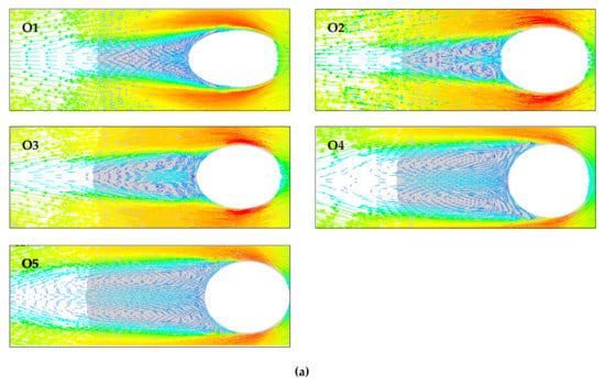

Figure 5.
Velocity vectors representing wake region formation behind the second row for: (a) oval and (b) flat tubes.
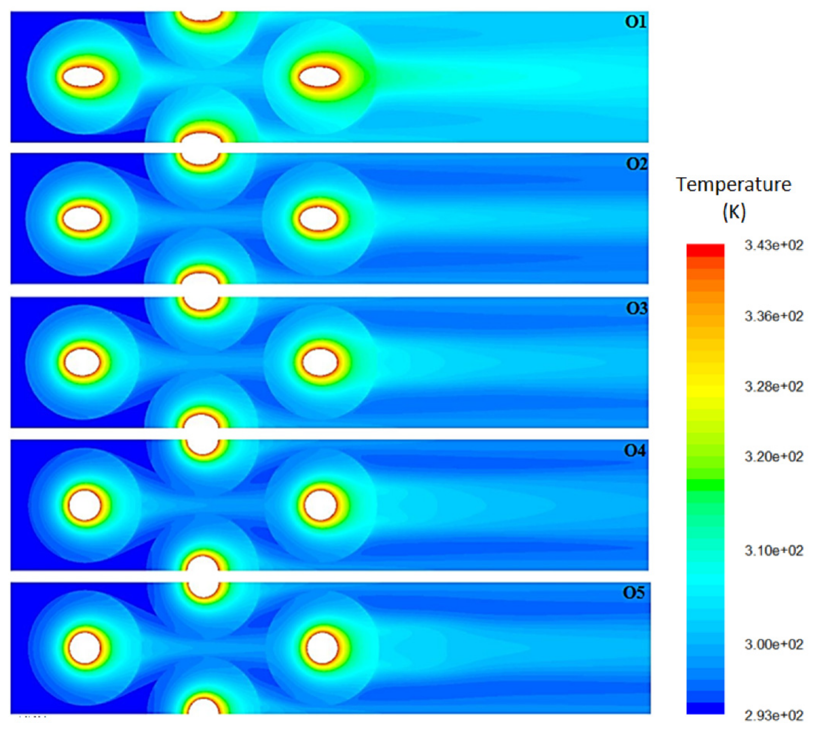
Figure 6 and Figure 7 show the local temperature distribution around the oval and flat tubes finned heat exchangers, respectively. The temperature distribution is presented in the middle of the fin thickness at a higher inlet velocity of air flow.
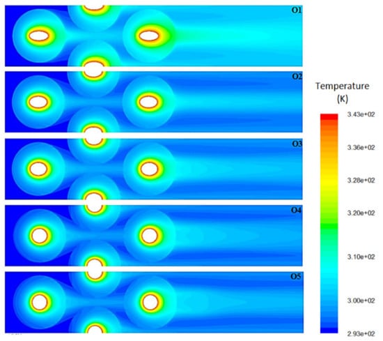
Figure 6.
Temperature contours in the middle of the fin thickness for all the geometries of the oval tube.
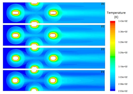
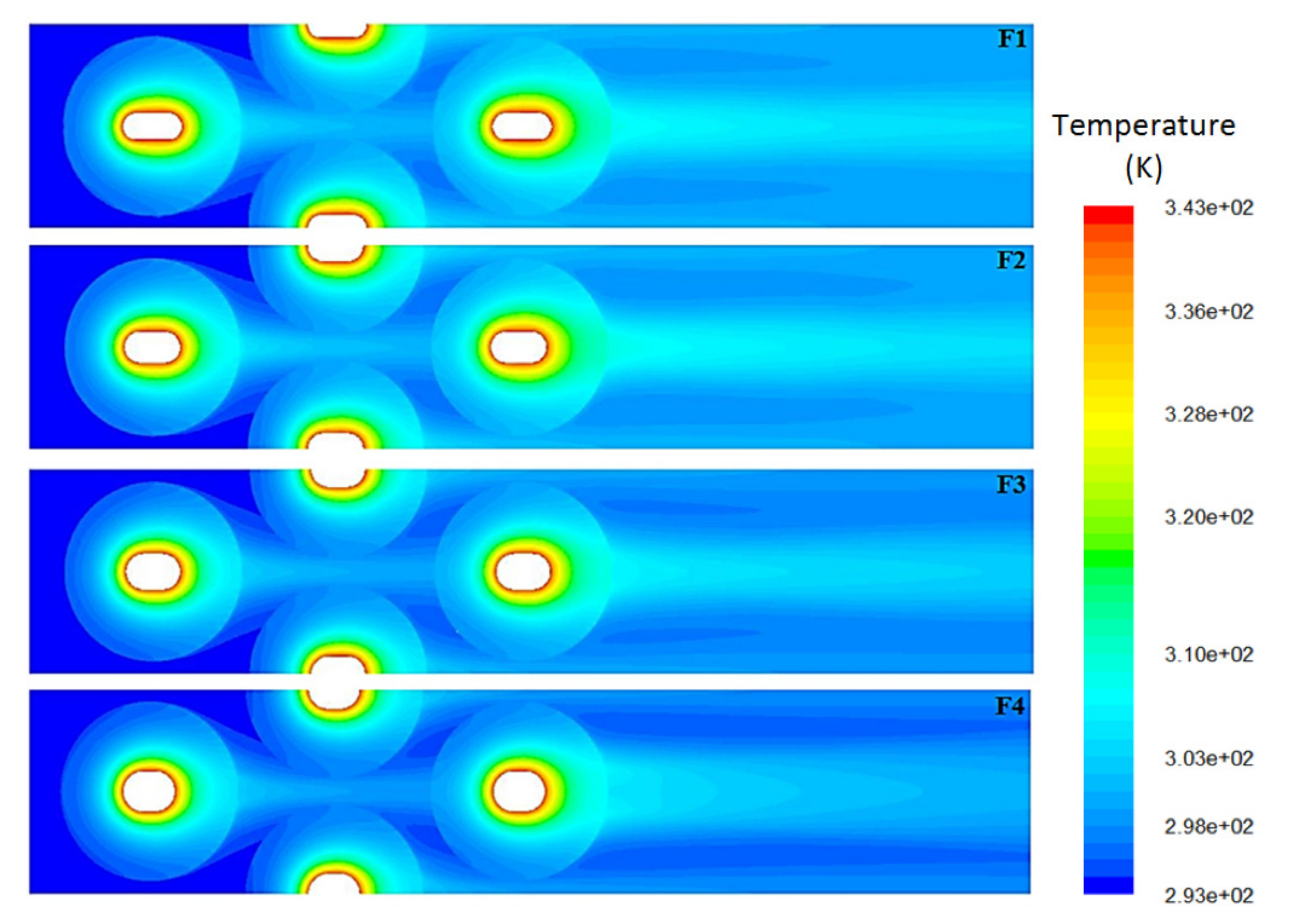
Figure 7.
Temperature contours in the middle of the fin thickness for all the geometries of the flat tube.
Bigger temperature gradients along with the longitudinal flow direction of oval-shaped tubes (O1, O2, O3, and O4) and flat-shaped tubes (F1, F2, F3 and F4) comparatively with the conventional circular tube (O5), indicate a larger global thermal exchange rate between the annular finned-tube and air flow, as the axis ratio of oval tubes and flatness of flat tubes increases air-side heat transfer increases. This might be due to the fact that the ellipticity and flatness of tubes reduce the area of the inactive zone of annular fins; moreover, the right and left sides of the fin surface, which are characterized by higher convective heat transfer, become more spacious.
Furthermore, increasing ellipticity and flatness of tubes raise the thermal exchange area of annular fins; for example, the circular finned-tube O5 can have up to 2.44% less surface area compared with the oval tube O1 and flat tube F1. For both oval and flat-shaped tubes, the temperature gradient at the downstream part of the fin surface is lower than the upstream due to the wake flowing behind the tubes.
4.2. Influence of Tube Shape on Heat Transfer and Pressure Drop
4.2.1. Oval Tube Finned Heat Exchanger
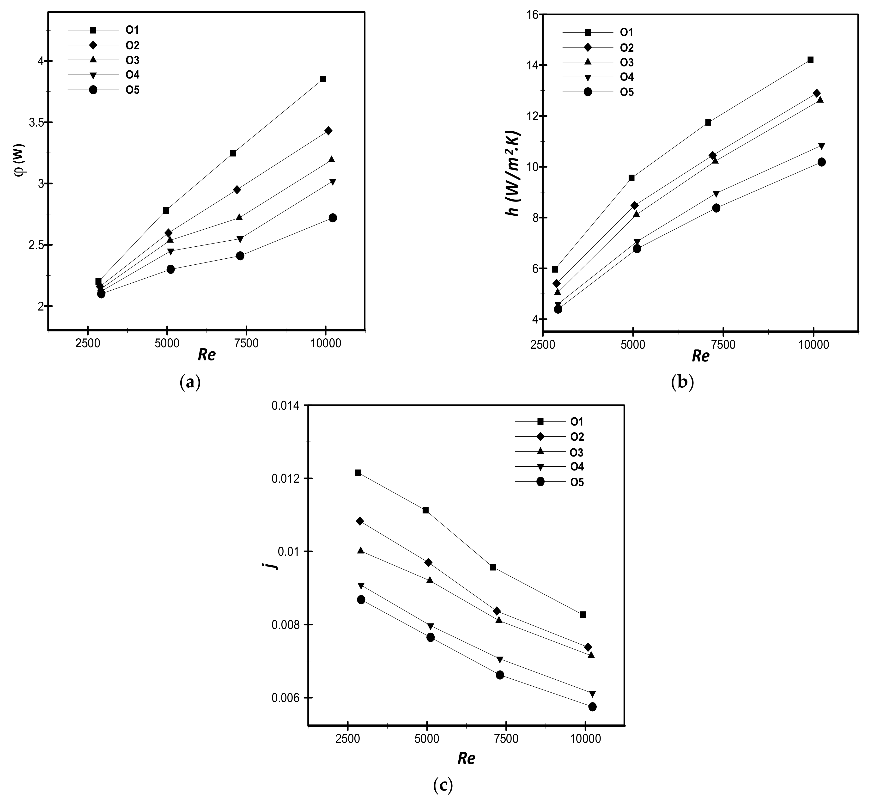
The thermal-flow characteristics of various oval tube shapes have been analyzed and compared in this section for a range of (2800 ≤ Re ≤ 10,200). The numerical results of heat transfer rate, convective heat transfer coefficient, and Colburn factor with different oval-shaped tubes are shown in Figure 8. The variation of heat transfer rate with the Reynolds number for each oval-tube shape is plotted in Figure 8a. augments strongly with Re for all tube geometries due to the substantial thermal exchange rate at high velocity. The heat transfer rate increases with the axis ratio, and the O1 tube shape outperforms the other tube geometries for the whole Reynolds number range. We can observe that the O1 tube shape provides 4–29% and 5–42% higher thermal exchange rates than the O4 tube shape and the conventional circular tube (O5), respectively.
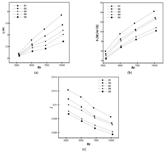
Figure 8.
Comparison of oval tube shapes at varying Res: (a) thermal exchange rate, (b) convective heat transfer coefficient, and (c) Colburn factor.
Figure 8b shows the convective heat transfer coefficient (h) versus Reynolds number for each oval tube design. Similar to the heat transfer rate, we can see that h increases with the increase of both axis ratio and Reynolds number (O1 tube shape provides 13–18% and 36–39% higher h values as compared to the O3 and O5 tube shape, respectively). This is due to the fact that the increase in the axis ratio reduces the area of the dead region (recirculation zone) behind each tube and enlarged the right and left sides of the fin surface, which are characterized by higher values of h.
On the other hand, it is crucial to explore the thermal exchange and flow behavior in terms of dimensionless numbers. Thus, the variation of the Colburn factor J with the air-side Reynolds number is depicted in Figure 8c. Similar to the overall heat transfer rate, J is the greatest for the O1 tube shape and the lowest for the circular tube (O5). Whatever the shape of the oval tube, the Colburn factor decreases with the rise of Re.
In the construction of heat exchangers, the permissible pressure drop (ΔP) is limited. As a result, examinations of the pressure losses are frequently conducted after assessments of heat transfer characteristics in these devices. As illustrated in Figure 9a, the ellipticity of tubes and Reynolds number has a strong impact on pressure drop through the annular FTHEs. For all Reynolds numbers, the ΔP values decrease as the axis ratio increase where the amount of ΔP for the circular tube is considered to be 17–23% higher than that for the O3 tube and about 38–48% higher than that for the O1 tube design, depending on the Reynolds number. This is due to the fact that the increase of tube axis ratio causes less energy to be received from the fluid pressure; thus, the value of the pressure drag force is reduced.
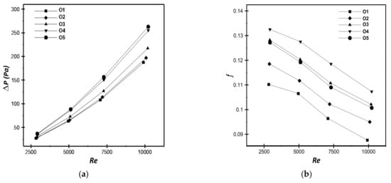
Figure 9.
Comparison of oval tube shapes at varying Reynolds number: (a) Pressure drop; (b) friction factor.
Figure 9b depicts the variation of the friction factor f for all of the inspected shapes of oval tubes at various Reynolds numbers. For all oval tube patterns, a rise in the Reynolds number results in a drop in f values. The maximum velocity and pressure loss augment with increased Re, but the resulting f decreases due to the dependence of f on the ratio of the pressure drop to the square of the maximum velocity (see Equation (14)). In addition, we can observe that O4 shows the higher values and O1 shows the lower values of f in comparison to other configurations. In fact, the O4 tube shape provides a 20–23% higher friction factor compared to the O1.
4.2.2. Flat-Tube Finned Heat Exchanger
As previously stated, another tube shape, namely the flat tube, is also analyzed in this work in order to determine the ideal tube configuration that delivers the highest thermal-flow performance. Aiming to inspect the effect of tube flatness, four geometries of flat tubes have been examined numerically in this study, as shown in Table 1. For all the flat-tube shapes, Figure 10a illustrates the thermal exchange rate vs. the Re. As highlighted, the thermal exchange rate increase with the tube flatness and the Reynolds number due to the reduction in the dead region and the increase of the heat transfer area of annular fins with the flatness of tubes. We can also observe that F1-shaped tubes outperform the other flat-tube geometries for the whole range of Reynolds numbers. The F1-shaped tube shows the increased heat transfer rate of 5.2% at Re = 2600 and 3.8% at Re = 10,200, compared to the O5 shaped tube.
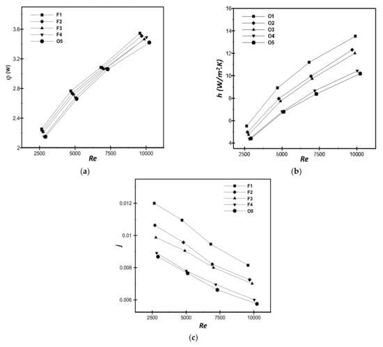
Figure 10.
Comparison of flat tube shapes at varying Reynolds number: (a) heat transfer rate, (b) convective heat transfer coefficient, and (c) Colburn factor.
Figure 10b shows the variation of the convective coefficient (h) for all of the inspected flat tube shapes at various Reynolds numbers. Of the flat tubes, the F1-shaped tube with annular fins provides 13–16% and 25–33% higher heat transfer coefficient compared to the F3 and O5 shaped tubes, respectively; the reason is the same as for the case of oval tubes in Figure 8b.
The variation of the non-dimensional Colburn factor J with the tube flatness for the range of 2600 ≤ Re ≤ 10,200 is depicted in Figure 10c. The simulations show that the decrease in flatness decreases for all the values of Re. All flat tubes reveal higher Colburn factor values than the circular tubes (O5), and the factors of all the flat tube geometries also decrease with Re.
The predicted pressure drop (ΔP) and friction factor f are plotted in Figure 11a,b, respectively. For the whole range of Re, the value of ΔP decreases with the increase of tube flatness (Figure 11a). We can observe that O5 and F3 tube shapes provide, respectively, 40–42% and 16–18% higher pressure losses compared with the F1 tube design; the cause is the same as that for oval tubes in Figure 9a. Moreover, the difference in the values of ΔP between the five patterns of flat tubes becomes considerable when the Reynolds number increases.
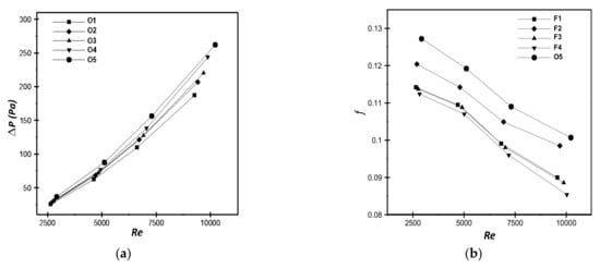
Figure 11.
Comparison of flat tube shapes at varying Reynolds numbers: (a) Pressure drop and (b) friction factor.
In Figure 11b, the values of f are illustrated for various flat tube geometries and Reynolds numbers. In contrary to the oval tube shape, F4 provides a lower f in comparison to the other tube geometries. The O4 tube shape provides a 13.2–18.5% lower friction factor than those of the other tube shapes when the Reynolds number increases from 2600 to 10,200. Furthermore, the circular tube has the highest f values of all examined flat-shaped tubes due to an increased blockage in air flow.
4.2.3. Impact of Tube Shape
The global performance criterion Gpc is employed to obtain the optimum configuration of tubes. For the five geometries of oval tubes, Figure 12a depicts the variation of Pec for the range of 2800 ≤ Re ≤ 10,200. O1 is clearly superior, not only to the conventional circular tube (O5), but also to all other tube designs for any value of Re. As expected, the performance evaluation criterion of O1 is higher by around 61.6–64.2% than that of O4, depending on Re. Generally, the performance Pec of the oval tube fin heat exchanger decreases as the ellipticity of tubes decreases, which is due to the higher heat transfer enhancement and lower pressure losses at a higher axis ratio. Furthermore, the difference of Pec between O4 and O5 is very small, where it does not exceed 1.8% for the whole range of Re. These results agree well with the numerical results of Zeeshan et al. [39] for the case of plate fins.
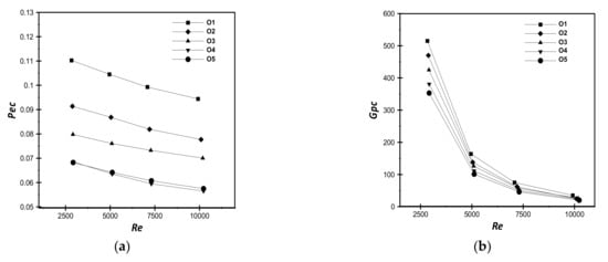
Figure 12.
Influence of oval tube shapes and Reynolds number: (a) performance evaluation criterion and (b) global performance criterion.
Figure 12b shows the variation of the global performance criterion Gpc versus the Reynolds number for all of the oval tube geometries. It is a proven fact that when the axis ratio (RMX/RMN) grows, the heat transfer rate increases, but the power required by the fan ΔPV lowers, resulting in a greater thermal-hydraulic performance. Therefore, the O1 tube shape outdoes all the other tube designs in terms of Gpc, which is estimated to be 21.2%, 35.2%, and 45.9% higher than that for O3, O4, and O5, respectively, at lower values of Re. For the higher Reynolds number values, the difference in Gpc between all of the oval-shaped tubes becomes negligible. Finally, when the overall heat transfer and power consumption are taken into account, the O1 tube geometry provides the best thermal-hydraulic performance.
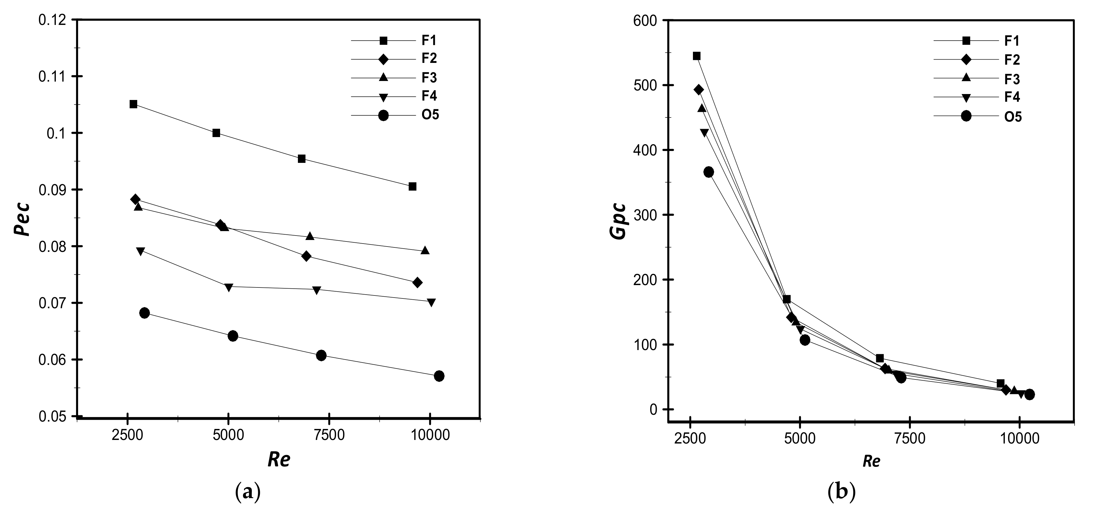
Similarly, the impact of the flatness tube on the performance evaluation criterion Pec and the global performance criterion Gpc is plotted in Figure 13a,b, respectively, for the range of Re of (2600 ≤ Re ≤ 10,200). As shown in Figure 13a, the pressure drop lowers as the flatness grows, implying that increasing the tube flatness would result in greater performance. For all the flat tube shapes, F1 shows the highest values of Pec. In addition, F1 provides 28.9–32.6% and 54–58.6% higher Pec than those for the F4 and O5, respectively.
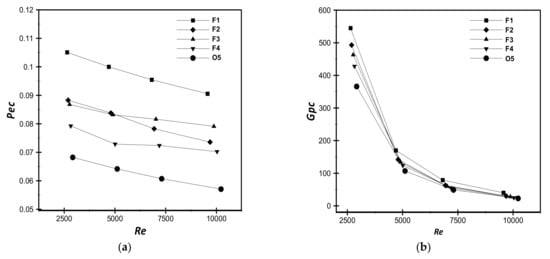
Figure 13.
Influence of flat tube shapes and Reynolds number: (a) performance evaluation criterion and (b) global performance criterion.
Figure 13b illustrates the variation of the Gpc versus the Reynolds number for all of the flat-shaped tubes. As observed, Gpc decreases rapidly with an increasing Reynolds number for the entire flat tube shapes because the fan power consumption grows rapidly in tandem with the sluggish increase in the heat transfer rate. For the whole range of Re, the Gpc offered by F1 tube geometry is the most substantial of all the other flat tubes, being 27.34–36% and 48.9–52.2% higher than the F4 and O5, respectively. This can be explained by the increase of heat exchange area and the decease of dead region when the flatness increases. However, the circular tube (O5) provides the lowest Gpc values at all Re because O5 requires more power consumption, hence shows worst thermal-flow performance.
5. Conclusions
In this paper, four shapes of the flat tube and four shapes of the oval tube have been investigated and compared with the conventional circular tube for the case of annular FTHEs. Furthermore, the findings were presented and compared in terms of performance evaluation criterion and global performance criterion Gpc vs. Reynolds number. For a range of Re of (2600 ≤ Re ≤10,200), the impact of the tube design on hydrothermal behavior for a three-row staggered bank was investigated. From the analysis of the numerical results obtained, the following main conclusions may be drawn:
- -
- For both oval and flat tubes, the heat transfer rate and the Colburn factor increases with the axis ratio and the flatness, whereas O1 and F1 provide the highest values.
- -
- Among the oval tubes, O1 produces the lowest friction factor values at all Re. However, the friction factor of F4 is lower than that for the other flat tubes (F4 provides 13.2–18.5% lower than those of the other tube shapes).
- -
- All the studied tubes (both oval and flat tubes) outperformed the traditional circular tube (O5) in terms of performance evaluation criterion, where O1 and F1 reached the greatest values at all Reynolds numbers.
- -
- Annular fins with the O1 tube shape outdo all the other oval tubes in terms of global performance criterion Gpc (higher by about 9.6%, 35.2%, and 45.9% than that of O2, O4, and O5, respectively, at lower values of Re). An increase in the flatness of flat tubes increases the Gpc values, where F1 shows highest values of Gpc among the four flat-tube geometries.
- -
- At all Reynolds numbers, F1 beats all other tube patterns. As a result, this tube geometry is suggested to be used in energy systems.
Author Contributions
Conceptualization, F.D. and L.B.; methodology, R.R. and M.I.; software, H.A. (Hijaz Ahmad) and F.T.; validation, H.A. (Houari Ameur) and G.L.; formal analysis, Y.M.; funding, S.K.E. and T.M.J. investigation, F.D. and R.R.; data curation, L.B.; writing-original draft preparation, M.I. and F.T.; writing-review and editing, H.A. (Hijaz Ahmad) and Y.M.; resources, H.A. (Houari Ameur) and G.L. All authors have read and agreed to the published version of the manuscript.
Funding
Taif University Researchers Supporting Project number (TURSP-2020/318), Taif University, Taif, Saudi Arabia.
Institutional Review Board Statement
Institutional Review Board Statement and approval number is not applicable.
Informed Consent Statement
No informed consent statement is required for this study.
Data Availability Statement
All data is available in manuscript.
Acknowledgments
Taif University Researchers Supporting Project number (TURSP-2020/318), Taif University, Taif, Saudi Arabia.
Conflicts of Interest
The authors declare no conflict of interest.
References
- Huang, J.; Jin, T.; Liang, M.; Chen, H. Prediction of heat exchanger performance in cryogenic oscillating flow conditions by support vector machine. Appl. Therm. Eng. 2021, 182, 116053. [Google Scholar] [CrossRef]
- Eidan, A.A.; Alshukri, M.J.; Al-fahham, M.; AlSahlani, A.; Abdulridha, D.M. Optimizing the performance of the air conditioning system using an innovative heat pipe heat exchanger. Case Stud. Therm. Eng. 2021, 26, 101075. [Google Scholar] [CrossRef]
- Qiu, S.; Xu, C.; Yang, Z.; He, H.; Xia, E.; Xue, Z.; Li, L. One-dimension and three-dimension collaborative simulation study of the influence of non-uniform inlet airflow on the heat transfer performance of automobile radiators. Appl. Therm. Eng. 2021, 196, 117319. [Google Scholar] [CrossRef]
- Deepika, K.; Sarviya, R.M. Application based review on enhancement of heat transfer in heat exchangers tubes using inserts. Mater. Today Proc. 2021, 44, 2362–2365. [Google Scholar] [CrossRef]
- Choi, J.; Lim, C.; Kim, H. Fork-end heat pipe for passive air cooling of spent nuclear fuel pool. Nucl. Eng. Des. 2021, 374, 111081. [Google Scholar] [CrossRef]
- Han, H.; He, Y.L.; Li, Y.S.; Wang, Y.; Wu, M. A numerical study on compact enhanced fin-and-tube heat exchangers with oval and circular tube configurations. Int. J. Heat Mass Transf. 2013, 65, 686–695. [Google Scholar] [CrossRef]
- Xie, G.; Wang, Q.; Sunden, B. Parametric study and multiple correlations on air-side heat transfer and friction characteristics of fin-and-tube heat exchangers with large number of large-diameter tube rows. Appl. Therm. Eng. 2009, 29, 1–16. [Google Scholar] [CrossRef] [Green Version]
- Wan, R.; Wang, Y.C.; Kavtaradze, R.; Ji, H.Z.; He, X.L. Research on the air-side thermal hydraulic performance of louvered fin and flat tube heat exchangers under low-pressure environment. Exp. Heat Transf. 2020, 33, 81–99. [Google Scholar] [CrossRef]
- Naik, H.; Tiwari, S. Thermal performance analysis of fin-tube heat exchanger with staggered tube arrangement in presence of rectangular winglet pairs. Int. J. Therm. Sci. 2021, 161, 106723. [Google Scholar] [CrossRef]
- Zhang, L.; Tian, L.; Zhang, A.; Chen, H. Effects of the shape of tube and flow field on fluid flow and heat transfer. Int. Commun. Heat Mass Transf. 2020, 117, 104782. [Google Scholar] [CrossRef]
- Brenk, A.; Kielar, J.; Malecha, Z.; Rogala, Z. The effect of geometrical modifications to a shell and tube heat exchanger on performance and freezing risk during LNG regasification. Int. J. Heat Mass Transf. 2020, 161, 120247. [Google Scholar] [CrossRef]
- Kim, H.; Yoon, J.; Lee, H.Y.; Eoh, J.; Jeong, J.Y.; Lee, J. Design and thermal-hydraulic evaluation of the finned-tube type sodium-to-air heat exchanger in sodium test facility. Nucl. Eng. Des. 2020, 366, 110755. [Google Scholar] [CrossRef]
- Nemati, H.; Moghimi, M.A.; Sapin, P.; Markides, C.N. Shape optimization of air-cooled finned-tube heat exchangers. Int. J. Therm. Sci. 2020, 150, 106233. [Google Scholar] [CrossRef]
- Li, N.; Chen, J.; Cheng, T.; Klemeš, J.J.; Varbanov, P.S.; Wang, Q.; Yang, W.; Liu, X.; Zeng, M. Analysing thermal-hydraulic performance and energy efficiency of shell-and-tube heat exchangers with longitudinal flow based on experiment and numerical simulation. Energy 2020, 202, 117757. [Google Scholar] [CrossRef]
- Abbasi, H.R.; Sedeh, E.S.; Pourrahmani, H.; Mohammadi, M.H. Shape optimization of segmental porous baffles for enhanced thermo-hydraulic performance of shell-and-tube heat exchanger. Appl. Therm. Eng. 2020, 180, 115835. [Google Scholar] [CrossRef]
- Karuppasamy, M.; Saravanan, R.; Chandrasekaran, M.; Muthuraman, V. Numerical exploration of heat transfer in a heat exchanger tube with cone shape inserts and Al2O3 and CuO nanofluids. Mater. Today Proc. 2020, 21, 940–947. [Google Scholar] [CrossRef]
- Jiang, Q.F.; Pan, C.Y.; Chen, Y.D.; Zhang, Q.Y.; Tang, Y.B.; Aleksandr, P. Improved heat transfer and friction correlations of aluminum offset-strip fin heat exchangers for helium cryogenic applications. Appl. Therm. Eng. 2021, 192, 116892. [Google Scholar] [CrossRef]
- Alaqel, S.; El-Leathy, A.; Al-Ansary, H.; Djajadiwinata, E.; Saleh, N.; Danish, S.; Saeed, R.; Alswaiyd, A.; Al-Suhaibani, Z.; Jeter, S.; et al. Experimental investigation of the performance of a shell-and-tube particle-to-air heat exchanger. Sol. Energy 2020, 204, 561–568. [Google Scholar] [CrossRef]
- Wang, G.; Dbouk, T.; Wang, D.; Pei, Y.; Peng, X.; Yuan, H.; Xiang, S. Experimental and numerical investigation on hydraulic and thermal performance in the tube-side of helically coiled-twisted trilobal tube heat exchanger. Int. J. Therm. Sci. 2020, 153, 106328. [Google Scholar] [CrossRef]
- Fiebig, M.; Valencia, A.; Mitra, N.K. Local heat transfer and flow losses in fin-and-tube heat exchangers with vortex generators: A comparison of round and flat tubes. Exp. Therm. Fluid Sci. 1994, 8, 35–45. [Google Scholar] [CrossRef]
- Yoo, S.Y.; Park, D.S.; Chung, M.H. Heat transfer enhancement for fin-tube heat exchanger using vortex generators. KSME Int. J. 2002, 16, 109–115. [Google Scholar] [CrossRef]
- Du, X.; Feng, L.; Yang, Y.; Yang, L. Experimental study on heat transfer enhancement of wavy finned flat tube with longitudinal vortex generators. Appl. Therm. Eng. 2013, 50, 55–62. [Google Scholar] [CrossRef]
- Zaidan, M.H.; Alkumait, A.A.R.; Ibrahim, T.K. Assessment of heat transfer and fluid flow characteristics within finned flat tube. Case Stud. Therm. Eng. 2018, 12, 557–562. [Google Scholar] [CrossRef]
- Unger, S.; Krepper, E.; Beyer, M.; Hampel, U. Numerical optimization of a finned tube bundle heat exchanger arrangement for passive spent fuel pool cooling to ambient air. Nucl. Eng. Des. 2020, 361, 110549. [Google Scholar] [CrossRef]
- Darbari, A.M.; Alavi, M.A. Application of Taguchi method in the numerical analysis of fluid flow and heat transfer around a flat tube with various axial ratios. Int. Commun. Heat Mass Transf. 2021, 126, 105472. [Google Scholar] [CrossRef]
- Alnakeeb, M.A.; Saad, M.A.; Hassab, M.A. Numerical investigation of thermal and hydraulic performance of fin and flat tube heat exchanger with various aspect ratios. Alex. Eng. J. 2021, 60, 4255–4265. [Google Scholar] [CrossRef]
- Jang, J.Y.; Yang, J.Y. Experimental and 3D numerical analysis of the thermal-hydraulic characteristics of elliptic finned-tube heat exchangers. Heat Transf. Eng. 1998, 19, 55–67. [Google Scholar] [CrossRef]
- Saboya, S.M.; Saboya, F.E.M. Experiments on elliptic sections in one- and two-row arrangements of plate fin and tube heat exchangers. Exp. Therm. Fluid Sci. 2001, 24, 67–75. [Google Scholar] [CrossRef]
- Leu, J.S.; Liu, M.S.; Liaw, J.S.; Wang, C.C. A numerical investigation of louvered fin-and-tube heat exchangers having circular and oval tube configurations. Int. J. Heat Mass Transf. 2001, 44, 4235–4243. [Google Scholar] [CrossRef]
- Liu, M.S.; Leu, J.S.; Liaw, J.S.; Wang, C.C. 3-D Simulation of the thermal-hydraulic characteristics of louvered fin-and-tube heat exchangers with oval tubes. In Proceedings of the ASHRAE Annual Meeting, Minneapolis, MN, USA, 24–28 June 2000. [Google Scholar]
- Erek, A.; Ozerdem, B.; Bilir, L.; Zafer, I. Effect of geometrical parameters on heat transfer and pressure drop characteristics of plate fin and tube heat exchangers. Appl. Therm. Eng. 2005, 25, 2421–2431. [Google Scholar] [CrossRef] [Green Version]
- Lin, C.N.; Liu, Y.W.; Leu, J.S. Heat transfer and fluid flow analysis for plate-fin and oval tube heat exchangers with vortex generators. Heat Transf. Eng. 2008, 29, 588–596. [Google Scholar] [CrossRef]
- Tiwari, S.; Maurya, D.; Biswas, G.; Eswaran, V. Heat transfer enhancement in cross-flow heat exchangers using oval tubes and multiple delta winglets. Int. J. Heat Mass Transf. 2003, 46, 2841–2856. [Google Scholar] [CrossRef]
- O’Brien, J.E.; Sohal, M.S.; Wallstedt, P.C. Local heat transfer and pressure drop for finned-tube heat exchangers using oval tubes and vortex generators. J. Heat Transf. 2004, 126, 826–835. [Google Scholar] [CrossRef]
- Ibrahim, T.A.; Gomaa, A. Thermal performance criteria of elliptic tube bundle in crossflow. Int. J. Therm. Sci. 2009, 48, 2148–2158. [Google Scholar] [CrossRef]
- Sun, L.; Zhang, C.L. Evaluation of elliptical finned-tube heat exchanger performance using CFD and response surface methodology. Int. J. Therm. Sci. 2014, 75, 45–53. [Google Scholar] [CrossRef]
- Sun, L.; Yang, L.; Shao, L.L.; Zhang, C.L. Overall thermal performance oriented numerical comparison between elliptical and circular finned-tube condensers. Int. J. Therm. Sci. 2015, 89, 234–244. [Google Scholar] [CrossRef]
- Kumar, A.; Joshi, J.B.; Nayak, A.K.; Vijayan, P.K. 3D CFD simulations of air cooled condenser-III: Thermal–hydraulic characteristics and design optimization under forced convection conditions. Int. J. Heat Mass Transf. 2016, 93, 1227–1247. [Google Scholar] [CrossRef]
- Zeeshan, M.; Nath, S.; Bhanja, D. Numerical study to predict optimal configuration of fin and tube compact heat exchanger with various tube shapes and spatial arrangements. Energy Convers. Manag. 2017, 148, 737–752. [Google Scholar] [CrossRef]
- He, S.; Zhou, X.; Li, F.; Wu, H.; Chen, Q.; Lan, Z. Heat and mass transfer performance of wet air flowing around circular and elliptic tube in plate fin heat exchangers for air cooling. Heat Mass Transf. 2019, 55, 3661–3673. [Google Scholar] [CrossRef]
- Matos, R.S.; Vargas, J.V.C.; Rossetim, M.A.; Pereira, M.V.A.; Pitz, D.B.; Ordonez, J.C. Performance comparison of tube and plate-fin circular and elliptic heat exchangers for HVAC-R systems. Appl. Therm. Eng. 2021, 184, 116288. [Google Scholar] [CrossRef]
- Sakhri, N.; Draoui, B.; Menni, Y. Experimental study of earth to air heat exchanger performance in arid region. First step: In-situ measurement of ground vertical temperature profile for different depths. J. Adv. Res. Fluid Mech. Therm. Sci. 2019, 56, 183–194. [Google Scholar]
- Sakhri, N.; Moussaoui, A.; Menni, Y.; Sadeghzadeh, M.; Ahmadi, M.H. New passive thermal comfort system using three renewable energies: Wind catcher, solar chimney and earth to air heat exchanger integrated to real-scale test room in arid region (experimental study). Int. J. Energy Res. 2021, 45, 2177–2194. [Google Scholar] [CrossRef]
- Sakhri, N.; Menni, Y.; Chamkha, A.J. Heating capacity of an earth to air heat exchanger in arid regions—Experimental investigation. J. Appl. Comput. Mech. 2021. [Google Scholar] [CrossRef]
- Chamkha, A.J.; Menni, Y. Hydrogen flow over a detached v-shaped rib in a rectangular channel. Math. Model. Eng. Probl. 2020, 7, 178–186. [Google Scholar] [CrossRef]
- Boursas, A.; Salmi, M.; Lorenzini, G.; Ahmad, H.; Menni, Y.; Fridja, D. Enhanced heat transfer by oil/multi-walled carbon nano-tubes nanofluid. Annales de Chimie-Science des Matériaux 2021, 45, 93–103. [Google Scholar] [CrossRef]
- Chekchek, B.; Salmi, M.; Boursas, A.; Lorenzini, G.; Ahmad, H.; Menni, Y.; Ameur, H.; Merrah, M.; Fridja, D. Experimental study of the efficiency of a solar water heater construction from recycled plastic bottles. Int. J. Des. Nat. Ecodyn. 2021, 16, 121–126. [Google Scholar] [CrossRef]
- Hadidi, N.; Rebhi, R.; Bennacer, R.; Menni, Y.; Ameur, H.; Lorenzini, G.; Gepreel, K.A.; Ahmad, H. Thermosolutal natural convection across an inclined square enclosure partially filled with a porous medium. Results Phys. 2021, 21, 103821. [Google Scholar] [CrossRef]
- Menni, Y.; Ameur, H.; Yao, S.W.; Amraoui, M.A.; Inc, M.; Lorenzini, G.; Ahmad, H. Computational fluid dynamic simulations and heat transfer characteristic comparisons of various arc-baffled channels. Open Phys. 2021, 19, 51–60. [Google Scholar] [CrossRef]
- Menni, Y.; Chamkha, A.J.; Zidani, C.; Benyoucef, B. Baffle orientation and geometry effects on turbulent heat transfer of a constant property incompressible fluid flow inside a rectangular channel. Int. J. Numer. Methods Heat Fluid Flow 2020, 30, 3027–3052. [Google Scholar] [CrossRef]
- Menni, Y.; Azzi, A.; Chamkha, A.J.; Harmand, S. Effect of wall-mounted V-baffle position in a turbulent flow through a channel: Analysis of best configuration for optimal heat transfer. Int. J. Numer. Methods Heat Fluid Flow 2019, 29, 3908–3937. [Google Scholar] [CrossRef]
- Menni, Y.; Chamkha, A.J.; Zidani, C.; Benyoucef, B. Study of air flow around flat and arc-shaped baffles in shell-and-tube heat exchangers. Math. Model. Eng. Probl. 2019, 6, 77–84. [Google Scholar] [CrossRef]
- Ahmad, H.; Sakhri, N.; Menni, Y.; Omri, M.; Ameur, H. Experimental study of the efficiency of earth-to-air heat exchangers: Effect of the presence of external fans. Case Stud. Therm. Eng. 2021, 28, 101461. [Google Scholar] [CrossRef]
- Salmi, M.; Boursas, A.; Mederreg, D.; Lorenzini, G.; Ahmad, H.; Menni, Y.; Ameur, H.; Maoudj, R. Improved heat transfer in w-baffled air-heat exchangers with upper-inlet and lower-exit. Math. Model. Eng. Probl. 2021, 8, 1–9. [Google Scholar] [CrossRef]
- Ameur, H.; Sahel, D.; Menni, Y. Enhancement of the cooling of shear-thinning fluids in channel heat exchangers by using the V-baffling technique. Therm. Sci. Eng. Prog. 2020, 18, 100534. [Google Scholar] [CrossRef]
- Mahammedi, A.; Ameur, H.; Menni, Y. Investigation of the convective heat transfer and friction factor of magnetic Ni nanofluids within cylindrical pipes. Int. J. Sci. Technol. 2021, 8, 080101. [Google Scholar] [CrossRef]
- Maouedj, R.; Menni, Y.; Inc, M.; Chu, Y.M.; Ameur, H.; Lorenzini, G. Simulating the turbulent hydrothermal behavior of Oil/MWCNT nanofluid in a solar channel heat exchanger equipped with vortex generators. Comput. Modeling Eng. Sci. 2021, 126, 855–889. [Google Scholar] [CrossRef]
- Mon, M.S.; Gross, U. Numerical study of fin-spacing effects in annular-finned tube heat exchangers. Int. J. Heat Mass Transf. 2004, 47, 1953–1964. [Google Scholar] [CrossRef]
- Benmachiche, A.H.; Tahrour, F.; Aissaoui, F.; Aksas, M.; Bougriou, C. Comparison of thermal and hydraulic performances of eccentric and concentric annular-fins of heat exchanger tubes. Heat Mass Transf. 2017, 53, 2461–2471. [Google Scholar] [CrossRef]
- Orszag, S.A. Renormalization group modeling and turbulence simulations. In Near-Wall Turbulent Flows; Elsevier: Amsterdam, The Netherlands, 1993. [Google Scholar]
- Lin, C.N.; Jang, J.Y. A two-dimensional fin efficiency analysis of combined heat and mass transfer in elliptic fins. Int. J. Heat Mass Transf. 2002, 45, 3839–3847. [Google Scholar] [CrossRef]
- Kumar, A.; Joshi, J.B.; Nayak, A.K. A comparison of thermal -hydraulic performance of various fin patterns using 3D CFD simulations. Int. J. Heat Mass Transf. 2017, 109, 336–356. [Google Scholar] [CrossRef]
- Tahrour, F.; Benmachiche, A.H.; Aksas, M.; Bougriou, C. 3-D Numerical study and comparison of eccentric and concentric annular-finned tube heat exchangers. J. Eng. Sci. Technol. 2015, 10, 1508–1524. [Google Scholar]


Publisher’s Note: MDPI stays neutral with regard to jurisdictional claims in published maps and institutional affiliations. |
© 2021 by the authors. Licensee MDPI, Basel, Switzerland. This article is an open access article distributed under the terms and conditions of the Creative Commons Attribution (CC BY) license (https://creativecommons.org/licenses/by/4.0/).