1. Introduction
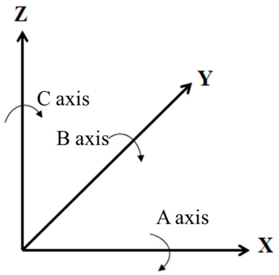
The five-axis machine tool is composed of three translational axes, (T), and any two rotary axes, (R) (3T2R). The definition of a rotary axis is based on ISO 230-2 [
1], as shown in
Figure 1. The machine tool used in this paper is a B-Type five-axis machine tool (UX300, Quaser Machine Tools, Taiwan) with a HEIDENHAIN controller iTNC530.
In recent years, the use of five-axis machine tools has been adapted more and widely. With the increasing number of rotary components, the accuracy of the machine tools is more important. The wear of the machine tools during the long processing time impacts the machine’s accuracy. The measurement and machine calibration must be carried out regularly to ensure the accuracy of the machine tools. Additionally, the error of the five-axis machine tool includes translational axis error and a rotary axis error total of 43 items. Translational axis errors have 21 items on three axes (X, Y, and Z), and rotary axis errors have 22 items on two rotary axes (AC). Each rotary axis has 11 errors, including 6 component errors and 5 location errors. The six component errors of the rotary axes change with the C-axis motion, as shown in
Figure 2.
Figure 2A shows the six component errors of the rotary axis, which are as follows:
EXC, radial error motion of C in X-direction;
EYC, radial error motion of C in Y-direction;
EZC, radial error motion of C in Z-direction;
EAC, tilt error motion of C around X-axis;
EBC, tilt error motion of C around Y-axis;
ECC, angular positioning error motion of C.
Figure 2B shows the five location errors of the rotary-axis, which are as follows:
XOC, error of the location of C in the X-axis direction;
YOC, error of the location of C in the Y-axis direction;
AOC, error of the orientation of C in the A-axis direction;
BOC, error of the orientation of C in the B-axis direction;
COC, error of the orientation of C in the C-axis direction.
If the NON-BAR [
2] instrument developed in the previous studies for ISO-10792-2 [
3] referred to measuring location errors on five-axis machine tools, this paper proposes a system named Laser R-test for angular positioning calibration (component error) and compensation of the five-axis machine tools, provides a simple measurement and calibration method, and maintains high precision for machine tools as a research target. Because the Laser R-test was designed based on the NON-BAR system, the Laser R-test could meet both ISO regulations ISO-10792-2 and ISO-230-2. In angular positioning, previous studies were developed with a laser diode, reflective grating, position-sensitive device, encoder, motor rotary table, or CCD [
4,
5]. The commercial instrument for machine tools angular positioning mostly uses a high-accuracy rotary table with an encoder and a laser interferometer, but the optical measurement path of these methods is easily affected by the concentric nature of the machine tool rotary table, and the correction of concentricity between the instrument and machine tools rotary table is time consuming.
In 2007, B. Bringmann [
6] used the constant relative position between the standard ball and the probe, so the geometric errors were measured in the standard ball of the device and showed X-, Y-, and Z-direction errors. In 2008, M. Sharif Uddin [
7] derived a model for eight motion errors of the rotary axis and three vertical errors of the translational axis by using a double ball bar (DBB), which improved on the machining accuracy. In 2013, Wang [
8] measured the volumetric error of machine tools’ workspace by three CCD cameras. In 2014, J. Chen [
9] used DBB to measure the relative distance between the spindle and the work table and calculated the geometric error of the machine tools through the homogeneous transformation model. In 2016, Jixiang Yang [
10] established a new PIGEs transformation matrix model, and through simulation and DBB measurement, PIGEs were able to predict the five-axis volumetric behavior at 5.39 μm, which validated the motion accuracy of the model. Renishaw [
11], Heidenhain [
12], and Blum [
13] are measurement devices for positioning error and five-axis geometric error. These measurement instruments are based on the assumption that three translational axes of a five-axis machine tool are measured without error, but in fact, there are still considerable errors in the three translational axes. IBS developed an R-test system [
14,
15,
16] for the machine tools five-axis simultaneous static error and dynamic assembly error. In 2018, Ch. Bao [
17] mentioned an instrument that could measure all the motion errors of a rotary axis, but in machining, translational and rotary components are in synchrony motions. Influences under this point will affect the result in reality. In 2019, H. Chen [
18] introduced a multi-station measurement system using a laser tracer applied on large high-precision rotary tables; however, the system faces concentricity problems between the laser tracer and the rotary table. In 2021, D. Ma [
19] executed a new measurement method as an independent system for all motion errors of a rotary axis based on a polyhedral prism. This experiment requires that the polyhedron and the rotary table are concentric after installation, otherwise, it causes unexpected errors.
From the literature mentioned above, it can be concluded that there are many measurement instruments, and most of them need to be performed by professional technicians to analyze measurement data. However, limitations and disadvantages still exist in each measurement method itself, such as concentricity problems and feasibility in applying methods. Therefore, the system in this study is proposed to measure both the five location errors and six component errors simultaneously and improve the mentioned issues.
The error of rotary axes and the error of translation along an axis merely cause the errors mentioned above. In order to reduce the errors as much as possible, we improve the accuracy of translational axes and rotary axes by measuring the values of error and compensating them to the corresponding axis. The process must be done in order. The translational axes should be done first, then the rotary axes. This study is going to focus on rotary axes and deploy analysis. The error compensation process on translational axes is not shown in detail but still needs to be done before taking any measurement for angular positioning error.
2. System Uncertainty Analysis and Calibration
2.1. Analysis
The rotary table of the five-axis machine tool is described by the blue circle shown in
Figure 3. The rotary table rotates a φ angle of 30 degrees, point A is the initial position, and point B is the current position. In order to estimate the uncertainty of the proposed system, the φ angle is derived in a mathematical equation by applying the Cosine theorem shown in Equation (1). The possible uncertainty factor is shown in Equation (2), and partial differentiation of the possible uncertainty factor can be shown in Equation (3).
The partial differentiation of each possible uncertainty factor is shown in Equations (4)–(6).
The distance between the measured angle position and the zero-angle point is shown in Equation (4).
The distance between the rotary center position and the zero-angle point is shown in Equation (5).
The distance between the measured angle position and the rotary center is shown in Equation (6).
The equation for the uncertainty could be defined as:
The positioning error of the machine tools translational axis will affect the distance of ; therefore, we put the following error values into the equation.
The distance between the rotary center position and the initial position is = 200 mm.
The distance between the current position and the rotary center is = 200 mm.
The distance between the current position and the initial position is = 103.5276 mm (if φ = 30 degrees) and = 34.8623 mm (if φ = 10 degrees).
The distance error between the current position and the initial position is .
The distance error between the rotary center and the initial position is = 2 μm.
The distance error between the current position and the rotary center is = 2 μm.
The uncertainty of this system is shown in Equation (7), and applying the above parameters yields the uncertainties for φ = 30 degrees and φ = 10 degrees, respectively.
That means the prediction uncertainty of the system could be re-written as follows:
φ = 30° ± 4.2 arcsec; or φ = 10° ± 1.31 arcsec.
2.2. Calibration
2.2.1. Translational Axis Calibration
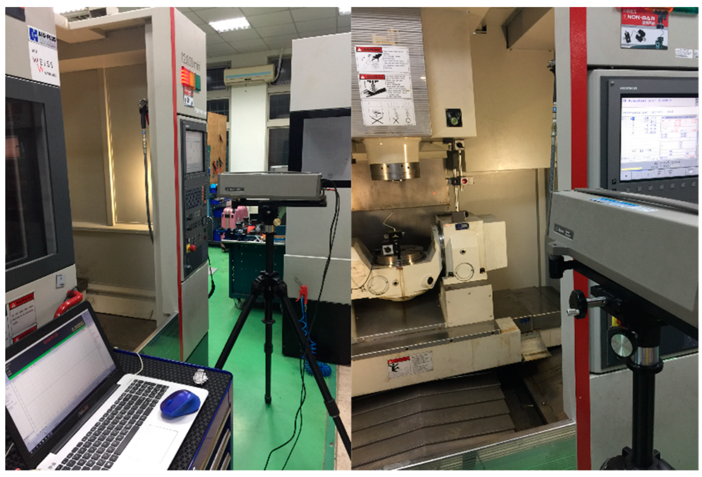
The location of point read from the CNC machine tool controller should be close to the actual location; the more accurate the read location is from the machine tool, the more accurate value of angular error is achieved later on. The compensating error process for translational axes was implemented by using the 5530 Laser Calibration System of Keysight Technologies on three axes, XYZ, as shown in
Figure 4. The results before and after compensation are shown in
Figure 5,
Figure 6 and
Figure 7. The error on the
X-axis after compensation is equal to 1 µm approximately, and the error is 2 µm approximately on the
Y-axis and
Z-axis. These values seem to be safe with the chosen values in uncertainty analysis before, and with these results they are in agreement with each other.
2.2.2. Eccentricity Calibration
The C-axis eccentricity measurement performed by XYC axis synchronous path called BK2 path as ISO 10791-6 standard is recorded every 45 degrees alone the entire trip of 360 degrees, which is repeated three times. The measurement results are shown in
Figure 8. The standard deviation before compensation was 1.6, the error of the
X-axis was 21.4 μm, and
Y-axis was 31.6 μm; the standard deviation after compensation was 0.6, the error of the
X-axis was 3.8 μm, and the
Y-axis was 8.9 μm. The A-axis eccentricity measurement performed by the YZA axis synchronous path called the BK1 path as the ISO 10791-6 standard is recorded every 15 degrees along the entire trip from −90 to + 30 degrees, which is repeated three times, and the measurements results are shown in
Figure 9. The standard deviation before compensation was 0.35, the error of the
Y-axis was 26.4 μm, and the
Z-axis was 44.1 μm; the standard deviation after compensation was 0.3, the error of the
Y-axis was 9.3 μm, and the
Z-axis was 10.3 μm.
In the above figures, the eccentricity under the influence of error on translational axes is described through these measurement results. On the other hand, before and after the compensation on the translational axes is seen in these results with a significant amount of reduced error.
3. System Measurement Method
In this paper, the rotary axis angular positioning measurement uses the linear encoder of the target machine tool to provide the machine coordinate: .
Suppose we have five points,
,
,
,
, and
with respect to machine coordinate frame
as shown in
Figure 10. Where the A point is the initial position of the ball lens, the B point and C point are the positions of the ball lens after rotating an arbitrary φ angle, the B’ point is the actual position of ball lens that the A point should rotate after, the O point is the center point of CNC machine table, and the θ angle is the error angle that needs to be calculated. The locations of A point, B point, and C point are given by CNC system
,
, and
, respectively. Considering the 2D coordinate (x, y), the circle with the center point
and radius r is defined by the Equation (10) in order to reduce mathematical calculation instead of the 3D coordinate (x, y, z) because the values on the
Z-axis will not be changed:
Substituting the location of three points (A, B, C) into Equation (10) yields the following:
Equation (10) could be achieved by solving the system of Equation (11) with the center point and the radius.
The
Figure 11 shows two coordinate frames, with frame
in the initial position and coordinate frame
being obtained by rotating table
by an angle φ. Considering the ball lens’ coordinate frame
, the
point indicates the error measured from the Laser R-test system (
and
). The coordinate frame
, with the
is obtained by using the Laser R-test system, and the angle error θ is defined by the
angle.
The location of the
point with respect to the machine coordinate frame
can be written as Equation (13). By projecting the
point onto the horizontal axis crossing the
point, we obtain the
point as shown in
Figure 12.
Applying Cosine theorem on
yields the following
The angle θ can be derived from Equation (14):
where “b” is the length of
and is determined as Equation (16).
where “h” and “d” are the lengths of
and
, respectively.
The value “a” can be determined by Equation (19) with respect to the coordinate frame
.
Substituting Equations (12), (13), and (16)–(19) into Equation (15) yields the following
Figure 13 presents the error that occurs after every operation on the rotary axis and those errors are calculated by using Equation (20). With two arguments, the B point and
point are read from the CNC machine system and Laser-R Test system, respectively.
4. System Configuration
The Laser R-test consists of two major modules: 1. The sensor module consists of two sets of the laser source, two photodetectors, an amplifier, an A/D converter, and wireless interface. 2. The ball lens module consists of a precision ball lens (diameter: 5 mm), ball bar, and holder. The key components of the Laser R-test are shown in
Figure 14. The Laser R-test has the following advantages: contactless measurement provides no wearing issue; it has high resolution, simple configuration, and easy installation; it is capable for A-, B-, and C-type machine tools and the turning-milling compound machine tool with the five-axis synchronous measurement path and multiple measurement items. The setup of the Laser R-test is that the sensor module and the ball lens module are respectively installed on the spindle and the worktable of the machine tool to be tested, and the ball lens should be placed inside the working range of the sensor module as shown in
Figure 15. The measurement principle does not require calibrating the concentricity between the measurement device and the rotary table. After the instrument hardware setup, the users input the ISO specification measuring path [
1,
2,
3] into the machine tool. The quadrant detector is used to measure the path of the ball lens trajectory; the difference of comparison with the machine coordinate of the machine tool can be used to analyze the linear axis backlash, rotation center, positioning, and five-axis assembly error of the machine tool. In this research, the commercial instrument XR-20 (Renishaw, UK) is used to verify and have a comparison with our Laser R-test. That process is deployed later. In this section,
Figure 16 shows the Renishaw XR-20 installed in different configurations to measure the A-axis and the C-axis, while the Laser R-test could measure different rotary axes without re-installing components. This advantage helps to save a lot of time while XR-20 needs to spend hours to re-configure the system.
At present, most industries use a high-precision rotary table installed on the rotary axis as the basis for measurement, which takes a lot of time to calibrate the concentricity between the instrument and the rotary table. Therefore, the system developed in this study uses the Laser R-test and uses the XYZ Cartesian coordinate system positioning signal with a Cosine theorem to measure each angular positioning error. This system can automatically compensate for each type of CNC controller (e.g., FANUC, HEIDENHAIN) to enhance the rotary axis positioning accuracy and efficiency of the machine tools, also significantly reducing the instrument installation time and measurement time. The angular positioning measurement process on the rotary axes is shown in
Figure 17.
5. Experiment and Results
All the angular positioning processes use the following configuration in the System Uncertainty Analysis and Calibration Section to keep adequate for the proposed system before:
The radius from the center of the rotary table: r = 200 (mm);
The measurement pitch: φ = 30 (degrees) for the C-axis and φ = 10 (degrees) for the A-axis.
5.1. Angular Positioning Measurement and Compensation
This section is for the angular positioning error of the rotary axis calibration. The compensation amount of the rotary axis error is provided by the measurement results. In this experiment, the C-axis is rotated from 0 degrees to 360 degrees, the measurement pitch is 30 degrees, and there is a total of 13 times. The A-axis is rotated from −90 degrees to 30 degrees, the measurement pitch is 10 degrees, and it is finished directly from forward to reverse measurement.
Figure 18 shows the error of the C-axis before compensation according to ISO230-2 regulation. The bidirectional positioning accuracy is 12.76 arcsec and the inverse error is 1.32 arcsec. The error of the C-axis after compensation is shown in
Figure 19. There is a bidirectional positioning accuracy of 4.49 arcsec and an inverse error of 1.68 arcsec.
Figure 20 shows the error of the A-axis before compensation. The bidirectional positioning accuracy is 15.12 arcsec, and the inverse error is 0.19 arcsec.
Figure 21 shows the error of the A-axis after compensation. The bidirectional positioning accuracy is 2.03 arcsec and the inverse error is 0.48 arcsec.
The error reduced significantly through the results. The performances thus allow us to move forward and compare our system with other systems to see the feasibility of this study.
5.2. Angular Positioning Verification without Milling Workpiece
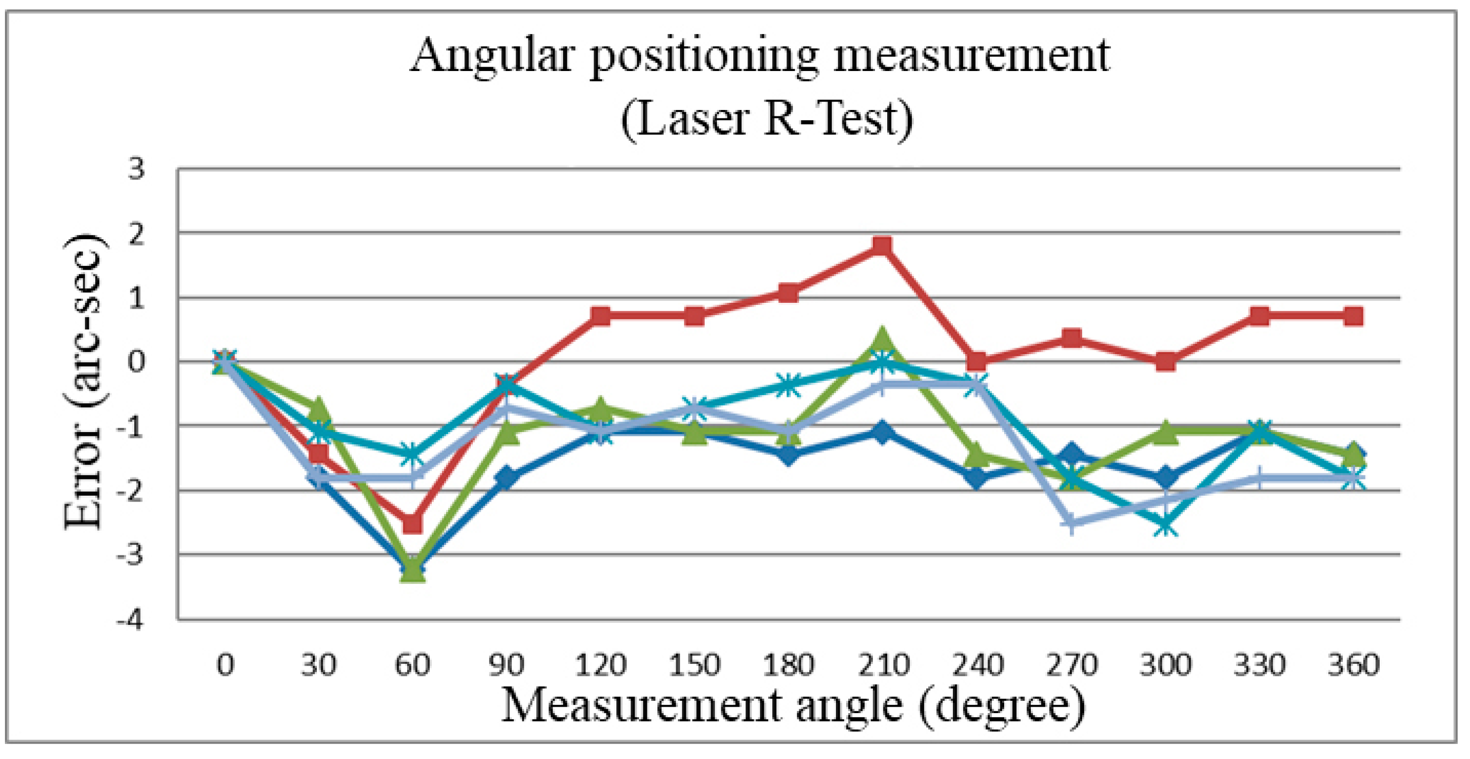
For the system verification, we compare the measured results of the Laser R-test with commercial instrument XR-20 (Renishaw, UK) after compensations, and the measurement is executed five times for each instrument. The measured results shown in
Figure 22 and
Figure 23 are as follows: for XR-20, the accuracy is 4.7 arcsec and the repeatability is 5.5 arcsec; for the Laser R-test, the accuracy is 5.37 arcsec and the repeatability is 4.32 arcsec. The maximum residual error between the Laser R-test and XR-20 is 4.4 arcsec as shown in
Figure 24. The accuracy of XR-20 seems to be better for this case, but the repeatability of the Laser R-test is better. The Laser R-test had a better repeatability of 1.2 arcsec and worse accuracy of 0.67 arcsec compared to XR-20. In the measurement of the multi-body system, such as the five-axis machine tool, many components influence the accuracy of the measured results. The accuracy of measurements depends on measuring conditions. In this case, better repeatability describes the higher reliability of measurements.
The measured results show that this system shall be applied to the compensation of the rotary axis positioning. The error curve has an apparent convergence, so the system’s principles and methods are feasible in this experiment. However, these are just measurements. In order to demonstrate the feasibility of this research, in the next section, we apply the compensation values achieved from commercial instrument XR20-W and our Laser R-test on two actual workpieces.
5.3. Angular Positioning Verification with Milling Workpiece
The process is executed on one CNC machine tool but with two compensation data from the XR20-W and Laser R-test. The experimental process is shown in
Figure 25 excluding the translational axis compensation process done in advance. The workpieces after the process are put in an inspection by using the coordinate measuring machine (CMM) ABLE-686-CNC (Jingsh Meng Technology Co. Ltd., Taichung City, Taiwan) [
22]. There are two workpieces prepared, one for XR20-W and the other for the Laser R-test. They are cut by the following method, as shown in
Figure 26, with milling specifications as shown in
Table 1.
The captured result from CMM ABLE-686-CNC is archived by absolute measuring of the angles that the P1 path and every other path form, as shown in
Figure 27. The error result from
Figure 27 is re-expressed in
Figure 28, which shows the comparison of the two systems. Through these results, the performances of the XR-20 and Laser R-test (LRT) are very close.
Another measuring method on CMM ABLE-686-CNC is executed by relative measuring of the angles that the current path and next path form (P1 path and P2 path form, P2 path and P3 path form, …). In this method, the formed angles are equal to 150° theoretically.
Figure 29 shows the results of this method, and the following error shown in
Figure 30 shows two systems are equivalent.
Through these results with actual milling, we could demonstrate that our system is feasible in the real case.
After all the results, we have a picture of these experiments, including the system configurations (radius and measurement pitch) and the repeatability from the verification shown in
Table 2. This lists basic specifications of the Laser R-test yielded in this study, including comparison and deviation with XR-20 instrument. The radius and the measurement are two parameters that affect the performance of the system. Thus, these two parameters could be set to meet the requirement in different cases.
6. Conclusions
The measurement system was for angular positioning calibration and compensation of the five-axis machine tools. In this study, the uncertainties of the system are confirmed by using the Laser R-test and attempting to improve the angular error of rotary axes through compensations. The estimated uncertainty predictions and the observation in the measured results are satisfactory to each other. In order to prove the feasibility of this method, the experiments are executed including measurements, compensations, and verifications. The process ends up on actual workpieces with an angular error of 0.0121 degrees for the Laser R-test. Based on the measurement method, the system could avoid concentricity problems between instruments and the rotary table. The Laser R-test could be installed one time to measure both the C-axis and A-axis instead of re-installing components, because the measurement method simultaneously measures operations of both translational axes and rotary axes during sampling. Thus, the measured results are close to actual machining conditions and more reliable, but that means the translational axis calibrations and compensations are required using other measurement systems. That makes the system dependent; in other words, there is a limitation for cases where only the angular positioning calibration is required, and then, the system is not appropriate. However, those benefits of the system could improve the qualities and efficiency of the CNC machine tools, optimizing the process, especially for a full calibration that is required on all machine tools, including five-axis machine tools, before launching it to the market.


