Article

Sharp and Rounded Cutouts in a Chevron Orifice and Them Impact on the Acoustic and Flow Parameters of Synthetic Jet

Faculty of Mechanical Engineering, Bydgoszcz University of Science and Technology, Al. Prof. S. Kaliskiego 7, 85-796 Bydgoszcz, Poland
Appl. Sci. 2021, 11(20), 9624; https://doi.org/10.3390/app11209624
Submission received: 25 August 2021 / Revised: 12 October 2021 / Accepted: 13 October 2021 / Published: 15 October 2021
(This article belongs to the Special Issue Noise Reduction and Vibration Isolation)

Abstract

:
The application of a synthetic jet actuator in workplaces entails the necessity of noise reduction, which they generate. One of the methods to achieve this is the use of the chevron orifice or nozzle. Therefore, the impact of different numbers of chevrons and rounding of cutouts in the orifice on the actuator efficiency and the sound pressure level was tested. The chevron orifices were compared to the circular orifice. The time-mean reaction force method was used to measured efficiency and flow parameters, and the noise was measured according to the ISO 3746:2010. The rounded cutouts had an advantageous impact on the actuator efficiency at the power P > 1   W , while the efficiency of the actuator with classic chevron orifice was smaller than with circular orifice. The noise generated by the actuator with the chevron orifice was smaller from 0.6 to 1.6 dB than by the actuator with the circular orifice, at the number of chevrons equal to 7 or more. The rounding of cutouts in the chevron orifice can advantageously impact the parameters of synthetic jet actuators.

1. Introduction

The synthetic jet (SJ) is generated by the expulsion and injection of fluid into a closed cavity through an orifice or a nozzle. Firstly, the fluid is sucked into the cavity, and then expulsed as a jet. The jet is not being sucked to the actuator but moved away from the orifice and the vortices are formed at its edge. In this way, nonzero mass flow is synthesized at some distance from the orifice. However, because the time-mean mass flow in the orifice is zero, the SJ is called zero-net-mass-flux (ZNMF). The schematic way of SJ generation was presented in Figure 1. The synthetic jet actuator (SJA) can move the fluid using a loudspeaker [1], piezoelectric transducer [2], piston [3], or plasma [4].
The SJ has many applications and can be used in electronic cooling [1,3], mixing enhancement [4,5], flow control [6,7,8], or underwater propulsion systems [9,10]. Especially the first area of the SJ application is now developed and new types of actuators [11,12] are still developed to increase the efficiency of the cooling system. However, the use of the SJA in a cooling system is limited by the sound pressure level (SPL) specified in standards e.g., in EN ISO 9241-6:2002 [13]. The negative effect of noise on physical and psychological well-being was proven many times [14,15], and the noise level is included during the design of the work environment [16]. The SPL generated by the SJA is quite high and can be equal even to over 90 dB [17]. However, the noise is usually not so high and fluctuates close to 60 dB [18,19]. It makes that the way to reduce the SPL is sought, and the use of the chevron orifice is one of them.
The chevron nozzles are used mainly in aircraft to create the secondary jet crossed with primal jet. The cutouts in a nozzle wall induce stream vortices and that enhancement mixing between adjacent streams and in that way reduce the velocity gradient and as a result the noise [20]. The impact of the chevron edge of the nozzle on the flow structure and noise reduction was confirmed numerically [21,22] and experimentally [23]. The turbulent structure of the jet flow through the chevron nozzle makes that it can be used to heat transfer enhancement in impinging continuous jet, and also in impinging SJ [24,25].
The SJA with the chevron nozzle was investigated by Crispo et al. [26,27,28]. They investigated mainly the difference in flow organization in the case of SJ generated by the actuator with the circular nozzle and the chevron nozzle. The cutouts in the chevron office generate the streamwise vortices that alter the shape of the vortex ring [26]. It made that the vortex ring is not circular but more complex, but dissipate faster than vortices in the case of the circular nozzle. Smyk and Markowicz [29] showed that the time-average centerline velocity is the same for chevron and circular SJ in a distance x/d = 6, where x is an axial distance from the orifice and d is an orifice diameter. During, the centerline momentum velocity was the same, regardless of the type of orifice.
The other flow organization impact also on the time-averaged turbulent kinetic energy distribution. The chevron SJ topology affects the distribution of the Nusselt number on the cooling plate in the case of impinging SJ application. In effect, the chevron synthetic jet shows better heat transfer characteristics than the circular synthetic jet [27]. The impact of the chevron orifice on the heat transfer enhancement was also confirmed by Lyu et al. [25].
Crispo et al. [27] showed that except for the noncircular vortex ring the chevron SJA generated also the counter-rotating streamwise vortices in cutouts of the orifice. These structures have a significant impact on heat transfer enhancement.
Smyk and Markowicz [29] investigated the SPL of SJA with a chevron orifice. The orifice had the same number of chevrons but differed in the height of cutouts. Depending on the actuator power, the chevron orifice can decrease the noise generated by the actuator. The SPL increased for some cases, at power   P < 12   W , but in the case of the chevrons with the same height and width, the noise reduction was obtained at each investigated actuator power.
Mangate and Chaudhari [30] investigated the actuators with circular, diamond, and oval shape orifices. The highest noise was generated by the actuator with the circular orifice. The oval office was even about 13 dB quieter than the circular orifice at Reynolds number R e = 10 , 000 . The impact of the orifice shape on the generated noise was also investigated by Bhapkar et al. [18], Kanase et al. [19], and Smyk et al. [31]. Based on these papers, it can be observed that the circular orifice shape is one of the least favorable in terms of the noise generated by SJA. Arik [32] and Kanase et al. [19] investigate also the impact of the orifice length and showed that the increase of orifice length causes the SPL to decrease. The problem of noise reduction in SJA was widely discussed in [33].
In the paper [29], it was noticed that the sharp edge in the bottom of the chevron orifice can cause an increase in the SPL. So, if it is true, the rounding of this orifice can decrease the SPL generated by SJA. Of course, it may not be a cause-and-effect relationship, but it is an interesting and important point for the investigation of noise reduction in the SJA and other use of chevron orifice and nozzle. For this reason in this paper, the acoustic and flow parameter of SJA with a different type of chevron orifice was tested. The cutouts of the chevron orifice were sharp or rounded and the chevron number was different.

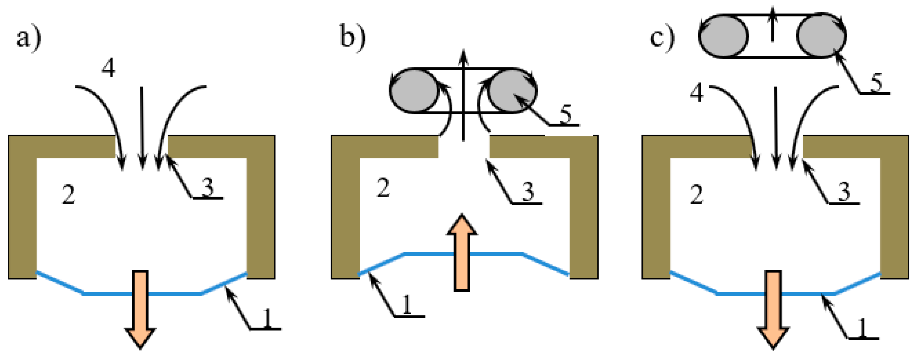
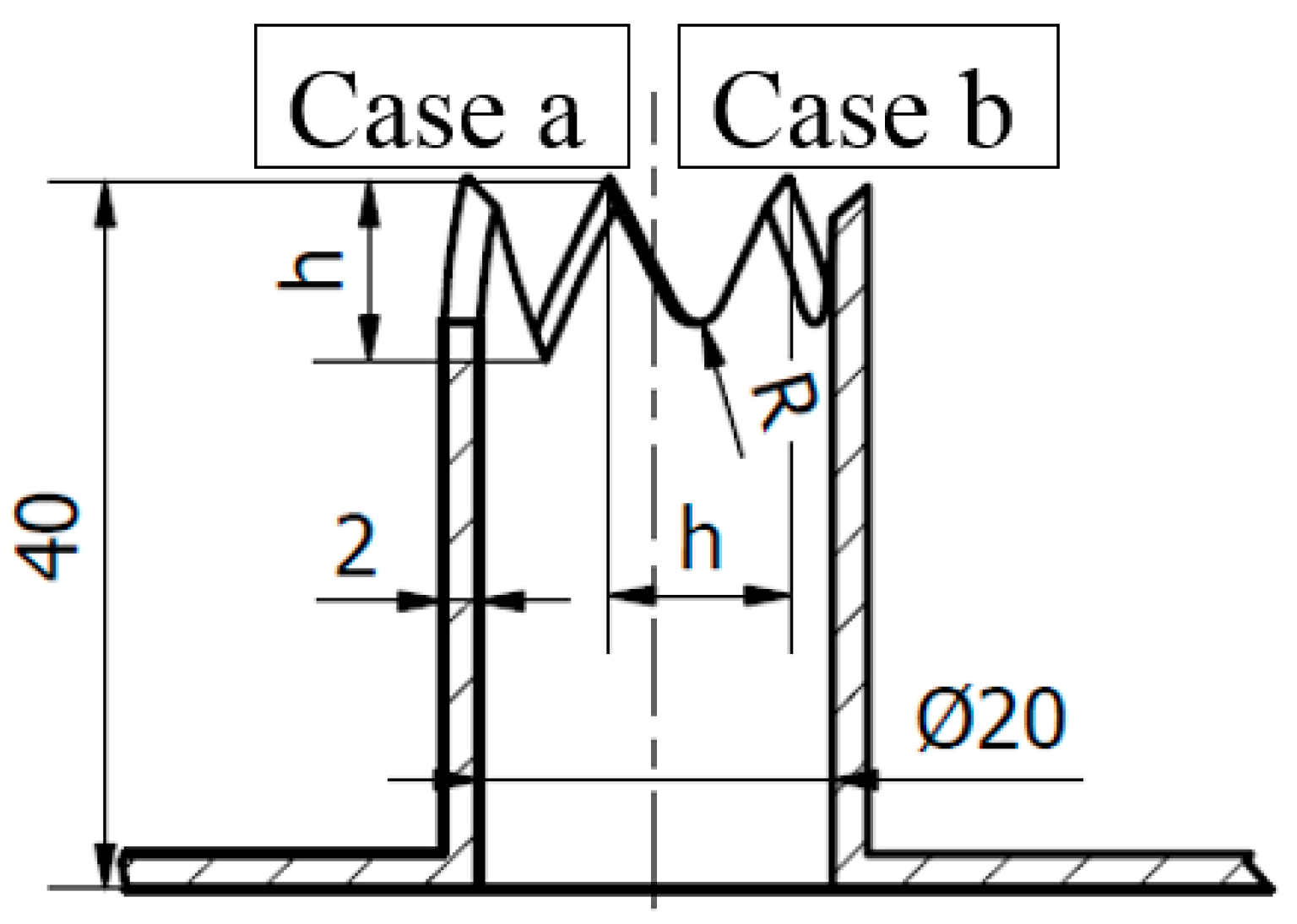
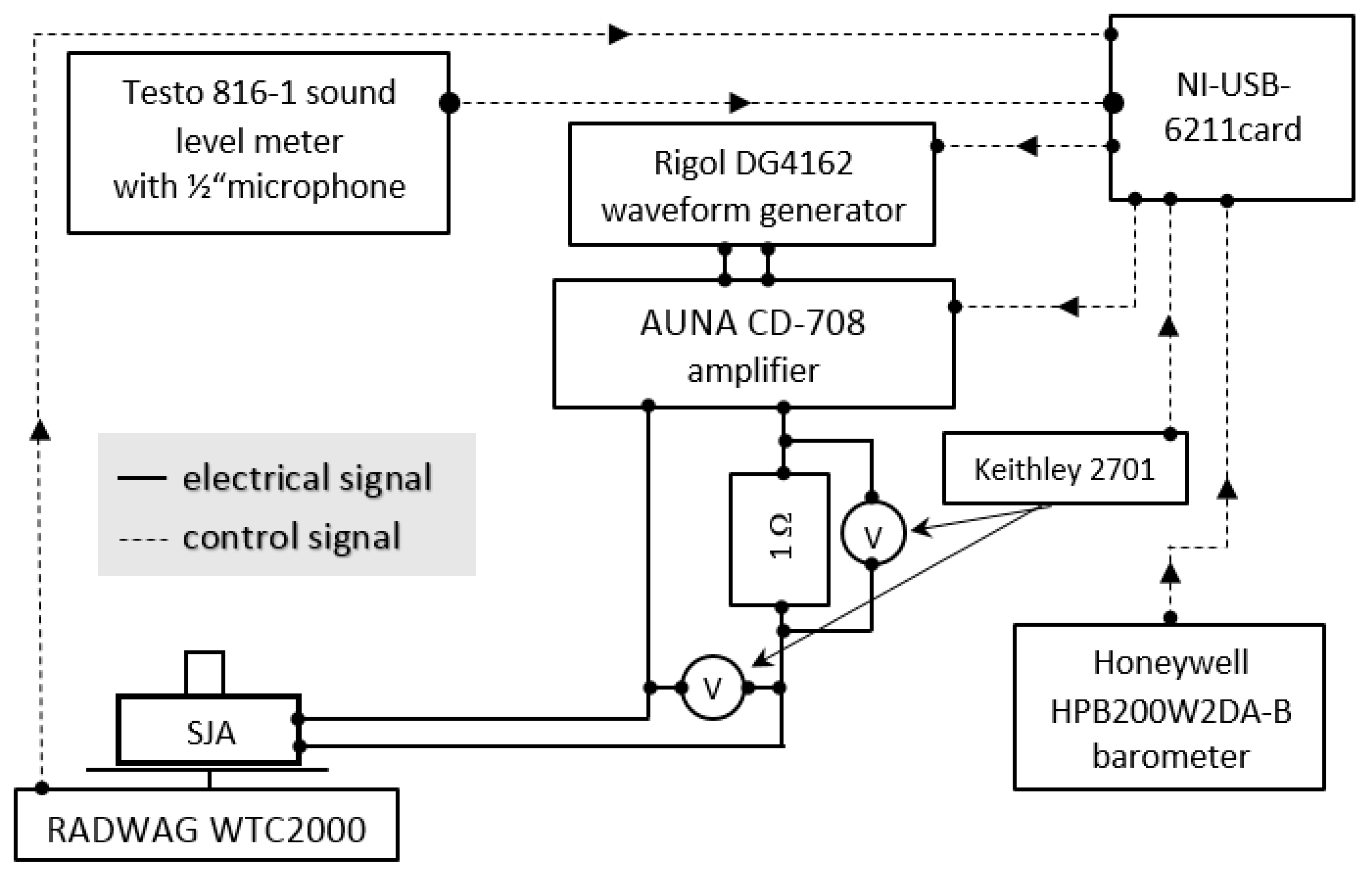
2. Materials and Methods

In the paper, SJA with nine different orifices were investigated. The first orifice was referenced and the orifice diameter was 20 mm and length 40 mm. The remaining was made based on the referenced orifice and differed in the number of chevrons. The chevrons were isosceles triangles with the same base and height length. In case “a”, the orifices were classic chevron orifice and in case “b” the top of cutouts was rounded with a radius equal to R = 1/6 h—both types of the orifices were presented in Figure 2. The actuator with reference orifice was tagged as a case 0, and the next orifices were marked with consecutive numbers. The dimensions of the orifices were presented in Table 1. The orifices were printed in 3D technology from PETG (polyethylene terephthalate glycol-modified).
The orifices were fixed with a four screw to the actuator body made from PMMA. The actuator body has a high of 20 mm and a diameter of 150 mm. The loudspeaker STH M.18.200.8.MCX was used. The same actuator but with other orifices was used in [29].
The actuator was supplied with sinusoidal signals generated by a Rigol DG4162 waveform generator and strung by an AUNA CD-708 amplifier. The effective voltage and effective current were measured with a Keithley 2701 mm instrument (6.5 digits, 22-bit) with a 7706 all-in-one I/O module. To the current measurements was used additionally a reference resistor (1 Ω, 0.01%)- as was presented in Figure 3.
The parameters of SJ were measured with the time-mean reaction force method described by Gil [34]. For this reason, SJA was measured with precision balance RADWAG WTC2000. The resolution of this device was 0.01 g, and the range was 2000 g. The SPL was measured with IEC 61672-1 Class 2 standard equipped with a 1/2 microphone. The measuring range was 35–130 dB (A) in a frequency range of 20–8000 Hz. The sound meter was located 1 m from the test stand. The background SPL of the environment was confirmed to be at least 10 dB lower than the SPL generated by the SJA. Type A frequency weighting was applied to the SPL measurements—SPL (A). The SPL was measured according to ISO 3746:2010 [35]. The same measurements method was used in [31,36,37].
Atmospheric pressure was measured using a Honeywell HPB200W2DA-B barometer, with an accuracy of ±40 Pa. All devices were controlled using LabVIEW software with the National Instruments NI-USB-6211 card. All devices and their connections were presented in Figure 3. The measurements uncertainty was presented in Table 2.

Data Reduction

The parameters of SJ and SJA were calculated based on the time-mean reaction force measurement [34], called also a thrust measurement [38]. The velocity of the SJ was defined as:
U = 1 2 F ρ · A
where F is a time mean reaction force [N], ρ is an air density [kg·m−3], and A = π d 2 4 is an orifice cross-section area.
The Reynolds number and dimensionless stroke length were calculated from:
R e = d ν F ρ · A
L / d = 1 2 f d F ρ · A
where ν is a kinematic viscosity of air [m2s−1], and f is a frequency of the loudspeaker actuator [Hz].
The efficiency of the actuator was calculated from [39]:
η = 1 2 P F ρ · A
where:
P = E I · cos ( φ )
where E is an effective voltage [V], I is an effective current [A], and cos ( φ ) is the power factor. The efficiency was calculated only for the resonant frequency, and for this reason, the power factor was approximate as cos ( φ ) = 1 . Gil and Smyk [39] and Smyk et al. [37] confirmed this dependence. However, it was used earlier [40].

3. Results and Discussion

In this section selected findings are presented. The data calculated on the time-mean reaction force measurement are presented initially, and then the SPL results. All measurements were performed at the constant power or a characteristic frequency. The formation criterion proposed by Milanovic and Zaman [41] L / d > 0.4 was fulfilled for all presented data. The Reynolds number was in a range of 1000–12,000.

3.1. Resonant Frequency

The first step of measurements was the finding of the natural frequency of the actuator. For this purpose, the SJ velocity as a function of frequency was presented in Figure 4. The natural frequency in cases 0, 3, and 4 was f n = 36 Hz, and in cases 1 and 2 was f n = 38 Hz. The frequencies were the same as in [29] for cases 0 and 1a.
The change of the resonant frequency in the case of the different numbers of chevrons is important in the case of natural frequency modeling. The different theoretical models take into account different parameters of actuators. The model proposed by Girfoglio et al. [42] does not include the influence of the orifice on the natural frequency. Broučková and Trávníček [40] and Kordík and Trávníček [43] propose the model included the length and diameter of the orifice. The differences in these models are described in more detail in [44].
According to the model of Kordík and Trávníček [43] the natural frequency is inversely proportional to the mass of the air in the orifice. This is especially noticeable when the natural frequency for the cases 0, 2, 5, and 6 will be compared—they are equal consecutively f n = 36 ; 38 ; 40 ; 42 Hz. The increase of the number (case 2) or the height (cases 5 and 6) of the chevrons affects the fluid mass in the actuator orifice and causes the increase of the natural frequency value. It is consistent with the model proposed by Kordík and Trávníček [43]. In case 1 the number of the chevron is too small. The change of the orifice volume is small compared to case 0 and a frequency change was not detected during the measurements (frequency step was equal to 2 Hz). The number of chevrons is equal to 10 in case 3 and 14 in case 4. In these cases, the height of cutouts is small compared to other cases and despite a large number of chevrons the natural frequency change was also not detected. In other words, the change (compared to case 0) of the orifice volume in cases 1, 3, 4 was too small to notice, for the adopted research methodology.
The impact of the orifice dimensions of the Helmholtz resonant frequency was described in [45]. Luca et al. [46] included in their model the mass of air in the orifice. Gil et al. [45] also include the mass of the air in the orifice but presented them as a function of length and diameter of the orifice.
Kordík and Trávníček [43] and Gil et al. [45] proposed the most extensive models taking into account many of SJA parameters. One of them is the mass of the air in the orifice. Both of the models were designated for the circular orifice. This paper showed that the chevron orifice has an impact on the natural frequency. In my opinion, it is caused by the change of the mass of the air oscillated in the orifice. Therefore, a way has to be found to determine this mass. This may be the subject of further research.

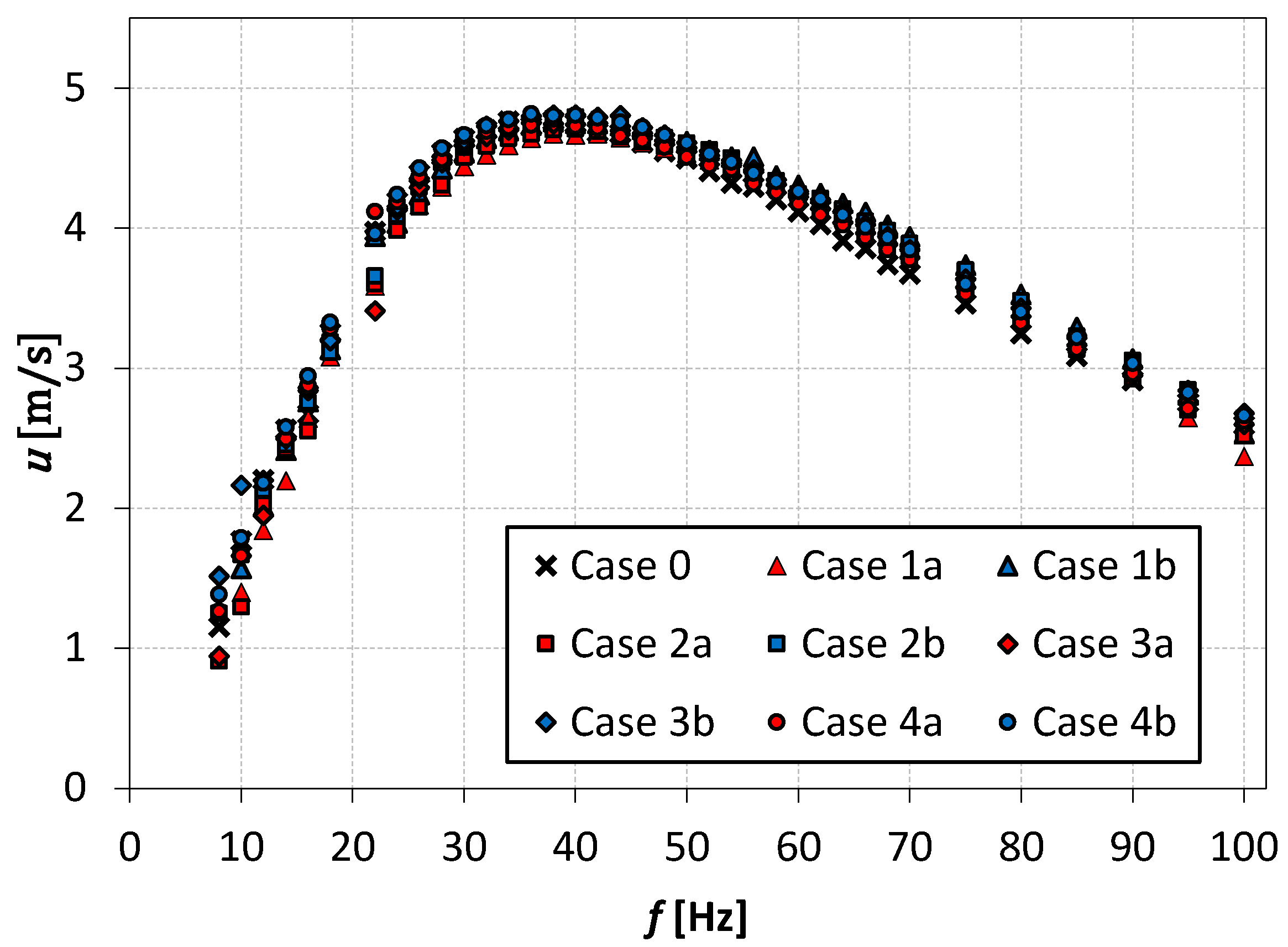
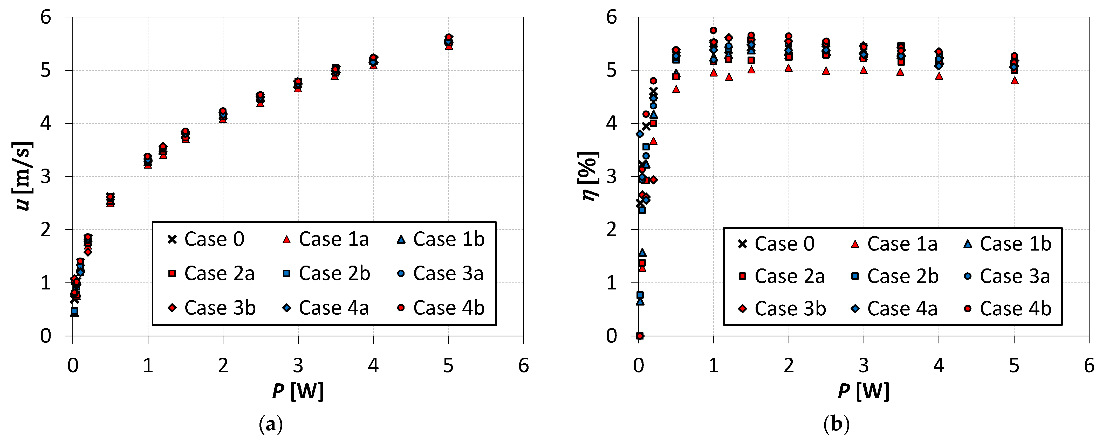
3.2. Flow Parameters
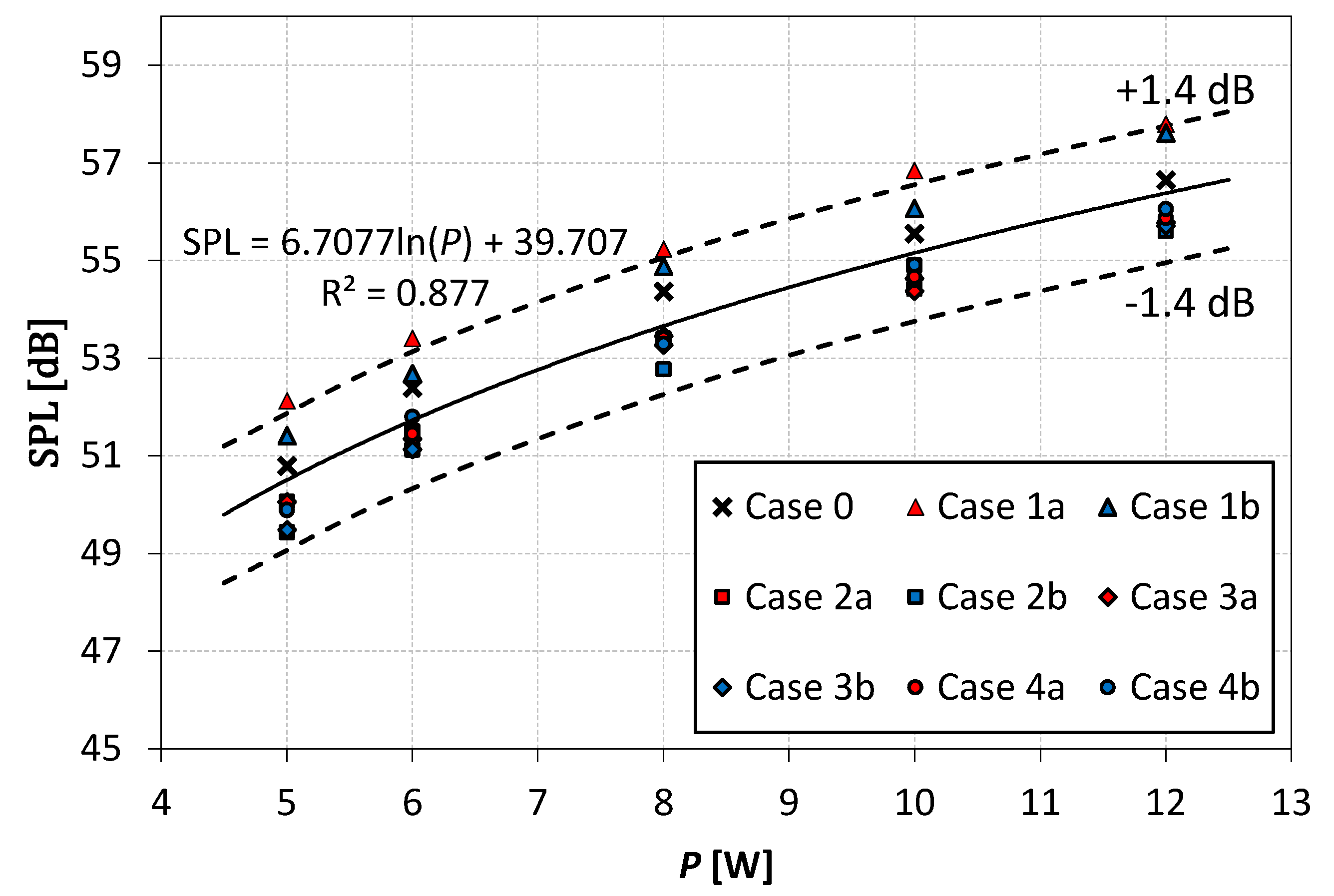
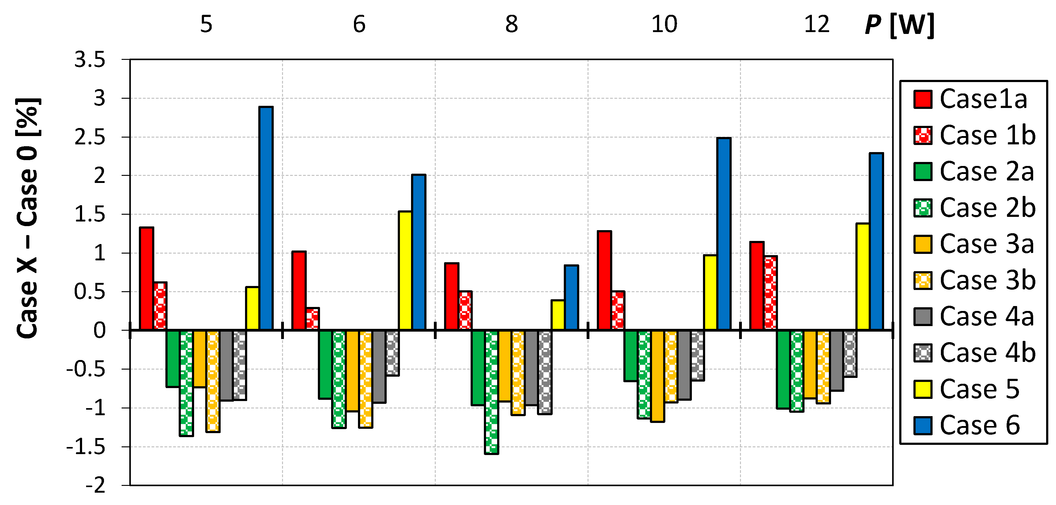
Figure 5 presents the SJ velocity and the efficiency of the actuators as a function of the electric power. The presented graphs had a classic form which can be observed in many papers [47,48]. However, the differences between cases are slight especially at the power above 1 W. For that reason, the differences between the actuator efficiency in case 0 and other cases were presented in Figure 6. The velocity and the efficiency are in the same way dependent on the time-mean reaction force (see Equations (1) and (4)), but the efficiency includes additionally the electrical power. Therefore, the dependencies presented in Figure 6 are similar in the case of velocity.
The impact of the number of chevrons on efficiency is quite complicated. In the case of classic chevron orifice (case a, Figure 6a), the chevron orifice has a generally negative impact on efficiency. Only at the power P = 1.2; 1.5; 2; 3 and 4 W the SJA with chevron orifice had higher efficiency than the SJA with circular orifice but only in cases 3a and 4a. Similar results were obtained by Smyk and Markowicz [29] (cases 5 and 6). However, the higher the number of chevrons the less impact of the chevrons on the efficiency.
In Figure 6, the absolute uncertainty of the efficiency was additionally marked. It is the uncertainty for one measurement and in the case when two different values are subtracted.
The absolute uncertainty should be doubled because considering the worst case possible:
( ( A = A ± 0.2 )     ( B = B ± 0.2 )   )   ( A > B     ( A 0.2 ) > ( B + 0.2 ) )
So, taking into account the measurement errors can be assumed that the chevron orifice has no impact on the efficiency at the power P 1.5   W .
In the case of chevron orifices with rounded cutouts (case b, Figure 6b), the impact on the efficiency is rather positive. Only at power P < 1   W the chevron orifice has a negative impact on the efficiency, and orifices with 4 and 10 chevrons (cases 1b and 3b) decreased the efficiency the most.
After considering the measurement uncertainty can be assumed that the chevron orifice has no impact on the efficiency at the power P 0.5   W .
Although the results differ slightly, it can be assumed that the increase of the chevron numbers with the rounding of the cutouts can increase the actuator efficiency. With the increasing of the chevron’s number, the difference of efficiency of the actuator with chevron and circular orifice disappears. This is due to increasing the geometric similarity of these two orifices—the bigger number of chevrons the smaller height of cutouts. Crispo et al. [26] showed that the cutouts are the area of counter-rotating vortices formation. These vortices modulated the shape of the vortex ring. During the increase of the number of chevrons, the modified vortex ring will look more and more like a classic vortex ring. Like a polygon with more and more sides, it looks more and more like a circle.
The rounding of the cutouts can increase the SJA efficiency (Figure 6b). The chevron orifice contains less volume of air than circular orifice and can cause lower orifice damping than circular (the inside surface of the orifice is smaller). Persoons et al. [49] showed that the orifice damping is positively correlated to the SJ velocity, and so to efficiency also. It can be expected that the efficiency of SJA with chevron orifice would be higher than in the case of the SJA with the circular orifice. However, this is not so. It means that the chevrons generate higher pressure losses than the circular outlet.
The results presented in Figure 6a showed that the SJA with chevron orifice has lower efficiency than at SJA with circular orifice, but the efficiency is higher in the case of SJA with rounded cutouts than at SJA with the circular orifice. These facts suggest that the sharp cutouts are unfavorable in terms of flow parameters and caused the losses of energy e.g., by the deflection of the stream. The rounding of cutouts reduces these effects and at higher velocity causes reduction of pressure loss, and consequently increases the efficiency of the actuator. Based on the presented results, it is impossible to make bolder conclusions, but this should be investigated in future studies.
The time mean-reaction method allows measuring only the primary flow parameters of the SJ. The flow visualization of the chevron SJ was made by Crispo et al. [26,27] for the actuator with a chevron nozzle. Therefore, it should be considered whether the SJ generated by the investigated actuators will be similar to those presented by Crispo et al.l [26,27]. This question can only be confirmed only with the use of the flow visualization. However, the velocity measurements presented by Smyk and Markowicz [29] suggest that it is so.
The increase of the SJ turbulence intensity in some distance from the orifice, significant differences in the values velocities (average, maximum, minimum), and increase of the actuator efficiency indicate that the chevron orifice has a direct impact on the flow organization of SJ.

3.3. Noise Level

The SPL was measures at the real power P = 5 ;   6 ;   8 ;   10   and 12   W , and it was presented in Figure 7. The noise level was in the range of 49 ≤ SPL ≤ 58 dB. Additionally, the logarithmic approximation based on all measurements point was presented in Figure 7 with a solid line, and the field of the measurement uncertainty was restricted with the dashed line. The differences between the SPL generated by the actuators with the chevron orifices and the circular orifice were presented in Figure 8.
The SPL differences presented in Figure 8 are small, and most of them are smaller than the measurement uncertainty (see Table 2). However, their distribution is not random, and the SPL generated by SJA with the chevron orifice is smaller than the SPL generated by SJA with the circular orifice at all cases, except cases 1a, 1b, 5, and 6. Additionally, in cases 1, 2, and 3, the smaller SPL was obtained at rounded cutouts than at classic, sharp. The SPL generated in case 4a was smaller than in case 4b only at power P = 8   W .
The SPL generated in case 1 was higher than in that of case 0. Based on the presented results, it is impossible to decide how the number of chevrons impacts the SPL, but a too-small number of chevrons increased the SPL. The number of chevrons should be dependent on the orifice diameter and not considered as an absolute number.
The obtained SPL reduction was similar to in the other papers. Jawahar et al. [50] obtained a higher SPL reduction of about 2.5 dB, at a Mach number equal to 0.3. Tide and Srinivasan [51] received approximately 4 dB reduction but at a Mach number range of 0.6–1.6. Akbarali and Periyasamy [52] showed that chevron orifice use can increase the SPL. Against this background, the presented results are correct and do not differ from the others. The presented noise reduction is smaller than the reduction obtained by the use of the other shape of the orifice. Mangate and Chaudhari [30] obtained the maximal SPL reduction about of 13 dB for the oval orifice, and Smyk et al. [31] about of 5.7 dB for the square office.

4. Conclusions

In this paper, SJAs with chevron orifices were tested. The orifices differed in the number of chevrons and the edges of cutouts were sharp or rounded (see Figure 2 and Table 1). The time-mean reaction force and the noise of actuators were measured. The Reynolds number was in a range of 1000–12,000.
The classic chevron (case a) orifices decreased the electrical efficiency of the actuator even about 0.5% (percentage points), at the real power P   1   W . The efficiency increase even 0.4% in case b. This shows, that the rounded cutouts in the chevron orifice can increase the efficiency of the actuator. The efficiency rise was small but this may indicate differences in the SJ formation.
The SPL was measured at the power of the actuator above 5 W. The noise reduction was obtained at the chevron number equal to 7 or more. The SPL was higher in cases 2a and 3a than in cases 2b and 3b. In case 4, the impact of rounded cutouts was unclear, but the SPL reduction was obtained only at P = 8   W . The received results are congruous to the results from other papers.
The paper showed that the chevron orifice with rounded cutouts can increase the efficiency of the actuator and can reduce the SPL more than a classic chevron orifice. It is very important due to the lot of noise generated by the SJA. In the case of investigated actuators, the SPL was in the range of 49 ≤ SPL ≤ 58 dB.

Funding

This work was supported by the National Center for Research and Development, Poland. Grant No.: LIDER/6/0024/L-10/18/NCBR/2019.

Institutional Review Board Statement

Not applicable.

Informed Consent Statement

Not applicable.

Data Availability Statement

All data generated or used during the study are available from the corresponding author by request.

Conflicts of Interest

The authors declare no conflict of interest.

References

  1. Gil, P.; Wilk, J.; Smusz, R.; Gałek, R. Centerline heat transfer coefficient distributions of synthetic jets impingement cooling. Int. J. Heat Mass Transf. 2020, 160, 120147. [Google Scholar] [CrossRef]
  2. Chiatto, M.; Palumbo, A.; de Luca, L. Design approach to predict synthetic jet formation and resonance amplifications. Exp. Therm. Fluid Sci. 2019, 107, 79–87. [Google Scholar] [CrossRef]
  3. Lyu, Y.W.; Zhang, J.Z.; Tan, J.W.; Shan, Y. Impingement heat transfer on flat and concave surfaces by piston-driven synthetic jet from planar lobed orifice. Int. J. Heat Mass Transf. 2021, 167, 120832. [Google Scholar] [CrossRef]
  4. Wang, P.; Shen, C. Characteristics of mixing enhancement achieved using a pulsed plasma synthetic jet in a supersonic flow. J. Zhejiang Univ. Sci. A 2019, 20, 701–713. [Google Scholar] [CrossRef]
  5. Bagherzadeh, A.; Jalali, E.; Sarafraz, M.M.; Akbari, O.; Karimipour, A.; Goodarzi, M.; Bach, Q.-V. Effects of magnetic field on micro cross jet injection of dispersed nanoparticles in a microchannel. Int. J. Numer. Methods Heat Fluid Flow 2019, 30, 2683–2704. [Google Scholar] [CrossRef]
  6. Hao, Z.; Liu, G.; Ren, W.; Wang, Y.; Bie, H. Research on the Characteristics of Bluff Body Wake Field Induced by Synthetic Jet with PANS Model. J. Appl. Fluid Mech. 2021, 14, 1053–1063. [Google Scholar] [CrossRef]
  7. Di Tommaso, R.M.; Fasanella, R.; Nino, E. Lean flame stabilization by means of a coaxial synthetic jet. J. Phys. Conf. Ser. 2020, 1589, 012019. [Google Scholar] [CrossRef]
  8. Gil, P. Bluff body drag control using synthetic jet. J. Appl. Fluid Mech. 2019, 12, 293–302. [Google Scholar] [CrossRef]
  9. Geng, L.; Hu, Z.; Lin, Y. Thrust and flow characteristic of double synthetic jet actuator underwater. Ocean Eng. 2019, 176, 84–96. [Google Scholar] [CrossRef]
  10. Krieg, M.; Mohseni, K. Dynamic modeling and control of biologically inspired vortex ring thrusters for underwater robot locomotion. IEEE Trans. Robot. 2010, 26, 542–554. [Google Scholar] [CrossRef]
  11. Gil, P. Performance of special type heat sink with an integrated synthetic jet actuator. E3S Web Conf. 2019, 100, 00017. [Google Scholar] [CrossRef] [Green Version]
  12. Gil, P. Experimental investigation on heat transfer enhancement of air-cooled heat sink using multiple synthetic jets. Int. J. Therm. Sci. 2021, 166, 106949. [Google Scholar] [CrossRef]
  13. International Organization for Standardization (ISO). EN ISO 9241-6:2002. Ergonomic Requirements for Office Work with Visual Display Terminals (VDTs)-Part 6: Guidance on the Work Environment (ISO 9241-6:1999); ISO: Geneva, Switzerland, 1999; p. 32. [Google Scholar]
  14. Colenberg, S.; Jylhä, T.; Arkesteijn, M. The relationship between interior office space and employee health and well-being—A literature review. Build. Res. Inf. 2021, 49, 352–366. [Google Scholar] [CrossRef] [Green Version]
  15. Bourikas, L.; Gauthier, S.; Khor, N.; En, S.; Xiong, P. Effect of Thermal, Acoustic and Air Quality Perception Interactions on the Comfort and Satisfaction of People in Office Buildings. Energies 2021, 14, 333. [Google Scholar] [CrossRef]
  16. Zhang, Y.; Ou, D.; Kang, S. The effects of masking sound and signal-to-noise ratio on work performance in Chinese open-plan offices. Appl. Acoust. 2021, 172, 107657. [Google Scholar] [CrossRef]
  17. Ikhlaq, M.; Yasir, M.; Ghaffari, O.; Arik, M. Acoustics and Heat Transfer Characteristics of Piezoelectric Driven Central Orifice Synthetic Jet Actuators. Exp. Heat Transf. 2021, 1–22. [Google Scholar] [CrossRef]
  18. Bhapkar, U.S.; Srivastava, A.; Agrawal, A. Acoustic and heat transfer characteristics of an impinging elliptical synthetic jet generated by acoustic actuator. Int. J. Heat Mass Transf. 2014, 79, 12–23. [Google Scholar] [CrossRef]
  19. Kanase, M.M.; Mangate, L.D.; Chaudhari, M.B. Acoustic aspects of synthetic jet generated by acoustic actuator. J. Low Freq. Noise Vib. Act. Control 2018, 37, 31–47. [Google Scholar] [CrossRef] [Green Version]
  20. Sadeghian, M.; Bandpy, M.G. Technologies for Aircraft Noise Reduction: A Review. J. Aeronaut. Aerosp. Eng. 2020, 9, 218. [Google Scholar] [CrossRef]
  21. Xia, H.; Tucker, P.G.; Eastwood, S. Large-eddy simulations of chevron jet flows with noise predictions. Int. J. Heat Fluid Flow 2009, 30, 1067–1079. [Google Scholar] [CrossRef]
  22. Khan, M.O.A.; Dhabi, A.; Khan, M.O.A.; Dhabi, A.; Dol, S.S.; Dhabi, A. Effects of Chevrons on the Acoustic Noise and Velocity Patterns of Aircraft Nozzles. In Proceedings of the 2020 International Conference on Decision Aid Sciences and Application (DASA) Effects, Sakheer, Bahrain, 8–9 November 2021; pp. 845–849. [Google Scholar]
  23. Violato, D.; Scarano, F. Three-dimensional evolution of flow structures in transitional circular and chevron jets. Phys. Fluids 2011, 23, 124104. [Google Scholar] [CrossRef] [Green Version]
  24. Guan, T.; Zhang, J.Z.; Shan, Y.; Hang, J. Conjugate heat transfer on leading edge of a conical wall subjected to external cold flow and internal hot jet impingement from chevron nozzle—Part 1: Experimental analysis. Int. J. Heat Mass Transf. 2017, 106, 329–338. [Google Scholar] [CrossRef]
  25. Lyu, Y.W.; Zhang, J.Z.; Liu, X.C.; Tan, X.M. Experimental investigation on convective heat transfer induced by piston-driven synthetic jet with a transmission pipe. Exp. Therm. Fluid Sci. 2019, 104, 26–42. [Google Scholar] [CrossRef]
  26. Crispo, C.M.; Greco, C.S.; Avallone, F.; Cardone, G. On the flow organization of a chevron synthetic jet. Exp. Therm. Fluid Sci. 2017, 82, 136–146. [Google Scholar] [CrossRef]
  27. Crispo, C.M.; Greco, C.S.; Cardone, G. Flow field features of chevron impinging synthetic jets at short nozzle-to-plate distance. Exp. Therm. Fluid Sci. 2019, 106, 202–214. [Google Scholar] [CrossRef]
  28. Crispo, C.M.; Greco, C.S.; Cardone, G. Convective heat transfer in circular and chevron impinging synthetic jets. Int. J. Heat Mass Transf. 2018, 126, 969–979. [Google Scholar] [CrossRef]
  29. Smyk, E.; Markowicz, M. Acoustic and flow aspects of synthetic jet actuators with chevron orifices. Appl. Sci. 2021, 11, 652. [Google Scholar] [CrossRef]
  30. Mangate, L.D.; Chaudhari, M.B. Heat transfer and acoustic study of impinging synthetic jet using diamond and oval shape orifice. Int. J. Therm. Sci. 2015, 89, 100–109. [Google Scholar] [CrossRef]
  31. Smyk, E.; Wilk, J.; Markowicz, M. Synthetic Jet Actuators with the Same Cross-Sectional Area Orifices-Flow and Acoustic Aspects. Appl. Sci. 2021, 11, 4600. [Google Scholar] [CrossRef]
  32. Arik, M. An investigation into feasibility of impingement heat transfer and acoustic abatement of meso scale synthetic jets. Appl. Therm. Eng. 2007, 27, 1483–1494. [Google Scholar] [CrossRef]
  33. Smyk, E. Acoustic aspects of synthetic jet - review. Dev. Mech. Eng. 2020, 16, 4. [Google Scholar] [CrossRef]
  34. Gil, P. Synthetic jet Reynolds number based on reaction force measurement. J. Fluids Struct. 2018, 81, 466–478, Corrigendum in 2021, 101, 103211. [Google Scholar] [CrossRef]
  35. International Organization for Standardization (ISO). Acoustics—Determination of Sound Power Levels and Sound Energy Levels of Noise Sources Using Sound Pressure—Survey Method Using an Enveloping Measurement Surface over a Reflecting Plane (ISO 3746:2010); ISO: Geneva, Switzerland, 2010; p. 48. [Google Scholar]
  36. Gil, P.; Smyk, E.; Gałek, R.; Przeszłowski, Ł. Thermal, flow and acoustic characteristics of the heat sink integrated inside the synthetic jet actuator cavity. Int. J. Therm. Sci. 2021, 170, 107171. [Google Scholar] [CrossRef]
  37. Smyk, E.; Przeszłowski, Ł.; Strzelczyk, P.M. Impact of the confinement plate on the synthetic jet. AIP Adv. 2020, 10, 105204, Erratum in 2021, 11, 039901. [Google Scholar] [CrossRef]
  38. Kordík, J.; Trávníček, Z. Integral Quantities of Axisymmetric Synthetic Jets Evaluated from a Direct Jet Thrust Measurement. Flow Turbul. Combust. 2019, 103, 827–844. [Google Scholar] [CrossRef]
  39. Gil, P.; Smyk, E. Synthetic jet actuator efficiency based on the reaction force measurement. Sens. Actuators A Phys. 2019, 295, 405–413. [Google Scholar] [CrossRef]
  40. Broučková, Z.; Trávníček, Z. Visualization study of hybrid synthetic jets. J. Vis. 2015, 18, 581–593. [Google Scholar] [CrossRef]
  41. Milanovic, I.M.; Zaman, K.B.M.Q. Synthetic jets in cross-flow. Part II: Jets from orifices of different geometry. In Proceedings of the 33rd AIAA Fluid Dynamics Conference and Exhibit, Orlando, FL, USA, 23–26 June 2003; pp. 1–12. [Google Scholar]
  42. Girfoglio, M.; Greco, C.S.; Chiatto, M.; de Luca, L. Modelling of efficiency of synthetic jet actuators. Sens. Actuators A Phys. 2015, 233, 512–521. [Google Scholar] [CrossRef]
  43. Kordík, J.; Trávníček, Z. Optimal diameter of nozzles of synthetic jet actuators based on electrodynamic transducers. Exp. Therm. Fluid Sci. 2017, 86, 281–294. [Google Scholar] [CrossRef]
  44. Smyk, E.; Wawrzyniak, S.; Peszyński, K. Synthetic jet actuator with two opposite diaphragms. Mech. Mech. Eng. 2020, 24, 17–25. [Google Scholar] [CrossRef]
  45. Gil, P.; Wilk, J.; Korzeniowski, M. Helmholtz Resonance Frequency of the Synthetic Jet Actuator. Appl. Sci. 2021, 11, 5666. [Google Scholar] [CrossRef]
  46. De Luca, L.; Girfoglio, M.; Coppola, G. Modeling and Experimental Validation of the Frequency Response of Synthetic Jet Actuators. AIAA J. 2014, 52, 1733–1748. [Google Scholar] [CrossRef]
  47. Smyk, E. Interference in axisymmetric synthetic jet actuator. EPJ Web Conf. 2017, 143, 02111. [Google Scholar] [CrossRef] [Green Version]
  48. Hernández-Sánchez, J.F.; Orduña-Bustamante, F.; Velasco-Segura, R. Momentum transfer in the outflow cycle of a Synthetic jet: Comparison between a developed flow and an LE model. arXiv 2021, arXiv:2106.14814. [Google Scholar]
  49. Persoons, T.; O’Donovan, T.S.; Donovan, T.S.O.; Persoons, T.; Donovan, T.S.O. A pressure-based estimate of synthetic jet velocity. Phys. Fluids 2007, 19, 2–5. [Google Scholar] [CrossRef] [Green Version]
  50. Jawahar, H.K.; Markesteijn, A.P.; Karabasov, S.A.; Azarpeyvand, M. Effects of Chevrons on Jet-installation Noise. In Proceedings of the AIAA AVIATION 2021 FORUM, Online, 2–6 August 2021; p. 2184. [Google Scholar]
  51. Tide, P.S.; Srinivasan, K. Effect of chevron count and penetration on the acoustic characteristics of chevron nozzles. Appl. Acoust. 2010, 71, 201–220. [Google Scholar] [CrossRef]
  52. Akbarali, I.M.; Periyasamy, S. Design and analysis of nozzle for reducing noise pollution. IOSR J. Mech. Civ. Eng. 2020, 17, 6–12. [Google Scholar] [CrossRef]
Figure 1. Generation of synthetic jet (SJ): (a) injection of fluid; (b) expulsion of fluid and SJ formation; (c) moving away of SJ and injection of a new volume of fluid to cavity (1—deformable diaphragm; 2—cavity; 3—orifice; 4—fluid injected to cavity; 5—synthetic jet).
Applsci 11 09624 g001
Figure 2. Schema of orifice.
Applsci 11 09624 g002
Figure 3. Measurements stand.
Applsci 11 09624 g003
Figure 4. SJ velocity vs. the actuator frequency at power 3 W.
Applsci 11 09624 g004
Figure 5. SJ velocity (a) and synthetic jet actuator (SJA) efficiency (b) as a function of power at resonant frequency f n .
Applsci 11 09624 g005
Figure 6. Efficiency differences between case 0 and cases a (a) and b (b).
Applsci 11 09624 g006
Figure 7. Sound pressure level (SPL) vs. real power.
Applsci 11 09624 g007
Figure 8. Differences between SPL generated by actuator with chevron orifice and circular orifice.
Applsci 11 09624 g008
Table 1. Dimensions and parameters of SJA orifices.
d [mm]l [mm]Number of Chevronsh [mm]R [mm]
Case 02040---
Case 1a2040418.85-
Case 1b2040418.853.14
Case 2a2040710.77-
Case 2b2040710.771.80
Case 3a2040107.54-
Case 3b2040107.541.26
Case 4a2040145.39-
Case 4b2040145.390.90
Case 5 [29]2040715.6-
Case 6 [29]2040720.8-
Table 2. Measurements uncertainty.
NameRelative UncertaintyAbsolute Uncertainty
Power, P±0.25%
Force, F ±1 mN
Efficiency, η ±0.2%
SPL ±1.4 dB
Publisher’s Note: MDPI stays neutral with regard to jurisdictional claims in published maps and institutional affiliations.

