1. Introduction
Carbon materials are among the earliest examples of man-made materials deliberately produced for a useful purpose. From those early times to the present day, flames have been exploited as the primary method to convert organic substances to materials such as carbon black [
1]. Many important industrial applications, including rubber reinforcement and pigmentation, rely on the carbon black commodity. Over the centuries, carbon particles have been produced in a variety of processes, but the furnace black process has been widely adopted as the most efficient and versatile method for industrial scale production [
2,
3,
4]. The furnace black process relies on flames to achieve high reactor temperatures, but the conversion of feedstock to carbon black particles occurs in a downstream pyrolysis process, separated from high-temperature oxidizing conditions. The carbon black industry has developed furnace processes for the production of aggregates with tailored primary particle size, aggregate morphology and surface functional groups. Selectivity in carbon black properties has been established for large-scale production by optimizing temperature, residence time and feedstock-to-air ratio with the addition of coagulation suppressant, in some cases [
2]. The current work examines the high-temperature conversion of feedstock to carbon black particles in flames, rather than a pyrolysis reactor. Flames introduce high-temperature oxidizing conditions, which result in a loss of the particle precursor to the gas-phase. However, the unique flame environment may result in useful carbon structure and surface properties without a pyrolysis reactor stage, and this may justify the lower particle yield.
The fossil fuel by-product known as carbon black feedstock is a mixture of heavy aromatic components originating from either the cracking of petroleum oil or the distillation of coal tars [
2,
3,
4]. The feedstock employed in the current study is distilled from tar components produced during the high-temperature coking of bituminous coal. Coal-sourced feedstocks were engineered to match the physical and chemical properties of the original petroleum-based feedstocks [
5] to ensure uniformity and compatibility with established carbon black processes. In the furnace black process, the heavy viscous feedstock is pre-heated to facilitate atomization and mixing before entering the pyrolysis reactor stage. The initial energy to reach the reaction temperature (typically 1500–2200 K) is furnished by the pre-combustion stage and partial combustion of the oil feedstock. The yield of the feedstock to carbon black is up to 70%, but high-surface area grades require higher reactor temperatures, which lowers the yield in these cases [
4]. The current work explores the formation of high-surface area carbon black without the use of a pyrolysis reactor. Rather, atomized carbon black feedstock is used to establish a piloted, turbulent spray flame at conditions conducive to carbon nanoparticle formation.
Similar to a flow reactor, flames have the potential provide tunable nanoparticle synthesis conditions within a certain range. The SpraySyn burner was introduced as a standardized spray flame configuration to systematically examine the conversion of involatile liquid precursors to nanoparticles [
6]. In the current work, the conversion of coal tar distillates to high-surface area carbon black is examined for a range of flame temperature and precursor feed rates. Spray flame synthesis has the potential for industrial scale production [
7,
8], and the implementation of the SpraySyn system may facilitate scale-up production based on the current work.
2. Materials and Methods
The current work is an experimental investigation of carbon black production in turbulent spray flames. Conventional piloted, turbulent spray flame nozzles use a co-axial jet or slot flames to support the combustion of the central spray [
9]. The narrow size scale of the pilot nozzle in conventional designs increases the required spatial resolution for flame modeling studies [
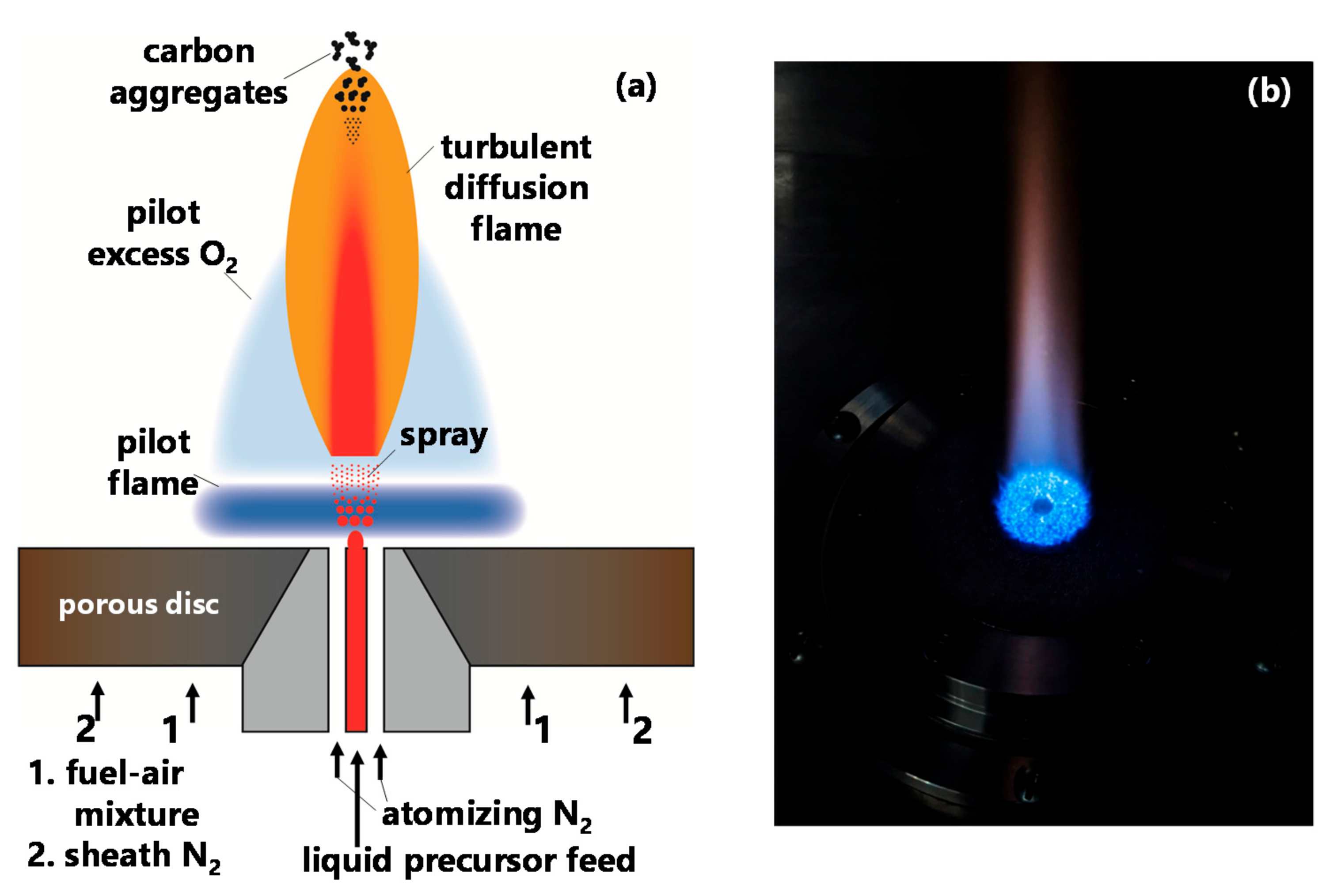
6]. To facilitate systematic studies, the pilot flame of the SpraySyn burner configuration is designed as a burner-stabilized flame with a larger domain to facilitate flame modeling with a coarse grid [
6]. The schematic of the SpraySyn burner, shown in
Figure 1, includes a porous metal disc which distributes the flow of the laminar pilot premixed fuel–air mixture. A larger area of this porous disc is also used to homogeneously issue a concentric inert nitrogen flow to shield and stabilize the synthesis process. An image of a typical pilot flame stabilized on the porous surface is shown in
Figure 1. The atomization of the liquid precursor feed is carried out by a two-fluid nozzle. Nitrogen gas is the atomizing fluid in the current work and the coal tar distillates liquid precursor injection rate is controlled by a syringe pump (KDS 100). The gas flow rates are controlled by calibrated critical orifices. More details of the SpraySyn burner design are discussed by Schulz and co-workers in their original instrumentation publication [
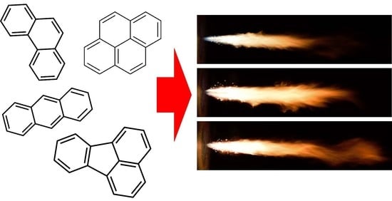
6]. The current vendor (Koppers Inc.) specifies their carbon black feedstock to be aromatic tar distillates obtained between 600 K and 700 K. Approximate composition is specified as containing up to 24% phenanthrene, up to 22% fluoranthene, up to 18% pyrene, up to 7% anthracene and up to 3% naphthalene with many other aromatic components specified [
10].
The burner system is housed in a closed polycarbonate chamber with height, width and depth of 1.2 m, 0.6 m and 0.8 m, respectively. Particles are captured from the flame 0.5 m above the burner surface from a 300 nm quartz filter (Sterlitech QR-200, Auburn, WA, USA) attached to a vacuum pump. The product particles are examined under TEM using a FEC Tecnai 12 with a Teitz 214 high resolution bottom-mounted digital camera. The TEM samples are prepared by collecting carbon black from the filter and suspending the particles in tetrahydrofuran. After sonicating to disperse the aggregates, a drop of the suspension is lowered onto a holey carbon-copper TEM grid. Raman spectra are obtained from the particle laden filter using a Thermo DXR2 Raman Microscope with a 532 nm excitation source for spectra, having Raman shifts spanning from 300 to 3000 cm−1. The laser is focused under a 50× objective at 1 mW power.
Flame images are obtained from a Nikon D5300 DSLR camera and the images are analyzed using a process designed by the developers of SpraySyn to define the spray flame height and width [
6,
11,
12]. A separate set of flame images are obtained from a Nikon D3500 modified to allow UV input to the CMOS sensor. A discussed in previous work [
13,
14,
15], a two-color pyrometry method, based on images obtained behind band-pass filters (450 nm, 650 nm, and 900 nm, Andover FS20, Salem, NH, USA), provides contour profiles of the soot particle temperature field. The ratio of radiative emission, detected by the sensor, is interpreted as follows:
where
GSλi is the greyscale output for the filtered camera sensor after transformation to a radial profile,
is the wavelength-specific calibration constant, relating the filtered camera sensor response to blackbody spectral intensity,
c is the speed of light,
h is the Planck’s constant,
k is the Boltzmann’s constant,
T is the temperature of the particle (assumed to be equal to the surrounding gas),
is the rated wavelength of the bandpass filter,
is the transmissivity of the filter and
is the full width at half maximum (FWHM) of the bandpass.
is calibrated using a blackbody furnace (Newport Oriel 67032, Irvine, CA, USA) while confirming the linear response of the camera sensor to intensity for a range of exposure times. The soot dispersion index,
α, is assumed to be unity under typical flame conditions [
16].
Thermocouple measurements of the pilot and spray flames are taken to complement the pyrometry measurements. A fine-wire type R thermocouple (125 micron wire, Omega P13R-005, Norwalk, CT, USA) is coated with a Y
2O
3/BeO ceramic, as outlined in previous studies [
17,
18], to minimize catalytic surface reactions on the platinum wire [
19]. Thermocouple readings are corrected for energy losses at the thermocouple bead, based on the known heat transfer behavior of fine-wire thermocouples in flames [
20,
21]. Temperature readings are recorded at 100 Hz to capture the flame temperature before the measurement is disrupted by soot deposits on the thermocouple bead. The current conditions are chosen to minimize temperature measurement challenges, previously reported in heavier sooting flames [
22,
23].
The two-flame series currently studied are outlined in
Table 1. The pilot fuel is ethylene gas kept at the same flow rate for all flames. Pilot nitrogen is also kept at the same flow rate across all flames in a flow independent of the pilot oxygen. The first series of flames examines the effect of excess oxygen in the pilot flame by systematically increasing the pilot oxygen flow rate to decrease the pilot flame equivalence ratio from 0.5 to 0.4. The liquid particle feedstock is coal tar distillates (Koppers Inc. carbon black feedstock, Pittsburgh, PA, USA) diluted in toluene (65% toluene, 35% distillate by volume in the first series) to decrease viscosity and to minimize the disruption due to liquid coking at the atomization nozzle. The second flame series keeps the pilot flow rates constant while steadily increasing the percent volume of coal tar distillate in the liquid feed from pure toluene to 75% coal tar distillates by volume (at 3 mL/min liquid feed flow rate). Future optimization of the atomization process is required to minimize the liquid coking of undiluted coal tar distillates. Series 1 uses an atomizing N
2 flow rate of 9.9 SLPM, while series 2 uses 10.8 SLPM. The flame-naming system uses “p” to denote the pilot flame equivalence ratio, “t” to denote the liquid feed toluene percent volume and “d” to denote the liquid feed coal tar distillates percent volume. The p43t65d35 condition is shared among the two series with the difference being a higher flow atomizing N
2 flow rate designated by the L and H labels. The sheath nitrogen flow rate is kept at 120 SLPM for all flames.
3. Results
Images of the spray flames provide insights into the flame dynamics and interaction with the pilot flame. Typical spray flame images for the Series 1 flames are shown in
Figure 2. In Series 1, the pilot flame is varied and the spray conditions are kept constant. The lowest pilot equivalence ratio (p40) corresponds to the highest oxygen flow entrainment to the spray because it is there that the most excess oxygen available. The p40 flame shows the tallest area of flame luminescence because the higher oxygen entrainment may result in a higher spray flame temperature. As the pilot oxygen flow rate is reduced, the equivalence ratio increases such that less excess oxygen is available for the spray flame. In general, the flame temperature of burner-stabilized flames decreases with decreasing flow rate and increases with increasing equivalence ratio. These two competing factors affect the appearance of Series 1 flames. Tall flame heights are maintained with an increasing equivalence ratio, perhaps due to increasing pilot flame temperature. Decreasing flame luminosity due to less available oxygen is also observed and the p50 pilot flame corresponding to the lowest oxygen is relatively short and dim. All flame images are captured at 1/3200 s shutter speed to prevent saturation in the brightest flame images and for comparable images across all flames. The observed range of flame conditions is expected to impact the production of flame-formed carbon black particles.
In Series 2 flames, the pilot flame is kept constant and the spray composition is modified to include a greater contribution of coal tar distillates. Typical flame spray images for Series 2 flames are shown in
Figure 3. Under this condition, the pure toluene spray flame shows lower visible emissions from the spray carbon flame particles. The addition of more coal tar distillate to the spray feed significantly increases the flame luminosity and the flame height. The greatest flame height observed for the 25% toluene/75% distillates spray flame may be due to the more carbon dense feedstock that induces a longer and stronger spray flame for the same oxygen entrainment. The presence of heavier precursor components is evidenced by bright burning droplets extending into the pilot flame for increasing coal tar distillate feed. The series of flame images imply that the formed carbon undergoes a range of growth times, growth temperatures and oxidation conditions, and these effects are discussed in terms of observed particle properties below.
Thirty flame images are taken for each flame condition and processed to obtain averaged flame height and width. The dimensions of the flame measured from the projected images are summarized in
Figure 4. Before taking flame images, a calibration pattern placed on the burner is imaged and processed in a procedure defined by Schulz and co-workers for defining the camera pixel-to-millimeter ratio [
6]. A peak flame height of 11.2 cm is observed for the p45 flame in Series 1 flames, but the lower equivalence ratio conditions also have comparable flame heights, considering the standard deviation across the images (reported as error bars). The measured flame width for the Series 1 flames lay within 10% of each other. Stronger trends in flame dimensions are observed for the Series 2 flames. As the flame images show, the toluene flame is relatively small and this corresponds to a spray flame height of 9.1 cm and width of 0.9 cm. The introduction of an increasing fraction of coal tar distillates to the spray feed increases the spray flame height and width up to 11.3 and 1.7 cm, respectively.
Flame temperature measured by thermocouple and soot pyrometry add further insights into the formation and growth environment of the carbon black particles. The temperature profile measured by thermocouple at the centerline of the pilot flames is shown in
Figure 5. As discussed above, the flame temperature of the burner-stabilized flames depends on the inlet flow rate and equivalence ratio of the fuel–air mixture. The measured temperature profile indicates that increasing the flow rate of oxygen causes a net increase in flame temperature at all distances above the burner despite lower equivalence ratio. The pilot flames of the SpraySyn burner are unique burner-stabilized flames, however, because a 0.6 cm island housing the spray nozzle assembly exists at the center of the burner surface (see
Figure 1). Without the spray, a stagnant zone exists at the centerline and this impacts the lowest flow rate pilot flame, p50, as exhibited by the peak flame temperature, delayed 2 cm downstream of the burner surface. The higher flow rate pilot flame temperature profiles are less impacted by this island. The maximum flame temperature is comparable across all equivalence ratio conditions but the lower flow rate of the p50 condition induces relatively lower temperatures at the burner boundary and further downstream. As discussed above, the temperature profile of the pilot flames is expected to directly impact the spray flame structure and carbon black particle properties.
The spray flame temperature is also measured by thermocouple at the centerline. The largest variation in spray flame temperature is expected to occur for Series 1 as the pilot flame temperature varies for constant spray inlet conditions. As such, temperature measurements are also taken by thermocouple and soot pyrometry for Series 1 to gain insight into the 2D axisymmetric flow field. The centerline thermocouple measurements, shown in
Figure 5, indicate that the low equivalence ratio pilot flame induces the highest flame temperature profile. The spray flame temperatures follow the same trend as the pilot flame center line temperature profiles with the highest flame spray temperature measured by thermocouple in Series 1 being 1850 K (flame p40) and the lowest spray flame temperature is 1555 K. The centerline thermocouple measurements for Series 2 flames are also shown in
Figure 5. The effect of increasing flame coal tar distillate on the temperature profile is less distinct than the effect of pilot oxygen flow rate. The 75% distillates spray flame is approximately 100 K hotter than the flame of pure toluene and the temperature difference extends to approximately 200 K 12 cm downstream of the burner. Overall, the trends in flame luminosity and size observed from the flame images carry over to the relative flame temperatures measured at the centerline.
Contour plots of the axisymmetric soot temperature field are extracted from images of the flame projection under 650 nm and 900 nm bandpass filters. Assuming a soot dispersion index of unity [
16,
24], contour plots of the Series 1 flames are shown in
Figure 6. The pyrometry camera is calibrated to detect soot radiative emissions from 1400 K to 2500 K and this results in flame images with smaller dimensions than the full flame images shown in
Figure 2 and
Figure 3. The temperature contours are an average of 20 flame images taken under each filter. Asymmetry in the temperature contour is detected but the multiple flame images are expected to reduce the impact of asymmetry on the Abel transform to some extent. Flame temperatures exceeding 2000 K are detected in local pockets of the turbulent spray flame as well. In principle, flame asymmetry and hot spots could be minimized by more precise centering of the liquid feed nozzle. Overall, the flame temperatures determined by soot pyrometry at the spray flame centerline agree with the thermocouple measurements shown in
Figure 5. The constant dispersion index assumption taken in the pyrometry measurements and differences in turbulent flow field averaging may be the source of discrepancies between the temperature measurement methods.
With the flame structure established, the properties of the flame-formed carbon could be examined more effectively. A summary of TEM images for carbon black, formed in both flame series, is shown in
Figure 7. The aggregate morphology is similar across all flame conditions but trends towards larger aggregates are noticeable for decreased equivalence ratio (Series 1) and increasing coal tar distillate spray feed (Series 2). Decreased oxygen levels in the flame are conducive to carbon particle formation, but the impact of flame temperature on particle formation is not monotonic. The optimum flame temperature is typically understood to lie at approximately 1800 K for soot formation in flames [
25,
26] and for yield in a carbon black pyrolysis furnace [
2,
4]. Kinetics for the growth of precursors is favored at higher temperatures, but growth reactions eventually reverse at higher temperatures [
27]. As such, the size of aggregates in Series 1 flames is a product of competing oxygen and temperature influences. For Series 2, increasing the fraction of coal tar distillates in the spray feed is expected to favor the formation and growth of carbon black due to the introduction of more aromatic particle precursors.
Primary particle diameters based on TEM particle projections are shown in
Figure 8 for both flame series. The median diameter of the histogram obtained from counting over 200 primary particles for each condition is reported. The median primary particle for the Series 1 flames increases by approximately 1 nm as the pilot flame equivalence ratio increases from 0.43 to 0.50. At lower equivalence ratio, the hotter spray flame temperature may favor carbon black production, but higher oxygen concentration in the spray increases particle oxidation thus hindering growth. Particle formation and growth kinetics are slower at lower flame temperature (p50), but lower oxygen concentrations may allow for a larger primary particle diameter.
For flame Series 2, the trend with increasing coal tar distillates is more significant than the effect of oxygen concentration. The median primary particle diameter is 8.5 nm for particle flames from pure toluene spray flames and increases to 16.5 nm for spray containing 75% coal tar distillates by volume. Increasing atomizing nitrogen flow rate is expected to decrease the spray droplet size and increase the entrainment of pilot flame gases into the spray. The p43t65d35 L and H conditions correspond to an increase in atomizing nitrogen flow rate by approximately 10%. The lower atomizing flow rate is more conducive to particle formation, as the median primary particle diameter is over 1 nm larger. All flame synthesis conditions reported here approach ASTM N110 carbon black, which is designated by primary particle sizes 15–19 nm [
2]. The current flame conditions could readily be manipulated to increase the primary particle diameter to obtain larger grades.
The carbon structure is examined by Raman spectroscopy for further insights into the flame-formed carbon black properties. Raman spectra obtained directly from the particle-laden collection filter are shown in
Figure 9 for Series 1 flames. Carbon materials are known be show prominent Raman scattering due to ordered graphitic sp
2 structural components (G peak) and disordered sp
2 components (D peak) [
28,
29]. The spectra are fitted for the D and G peaks with Lorentzian functions and a third peak attributed to amorphous components is fitted with a Gaussian, as previously defined for carbon black materials [
30,
31,
32]. The widths and relative intensities of the G and D peaks resemble Raman spectra, previously reported for various carbon black grades [
31,
33]. The intensity ratio of the D and G peaks is not sensitive to the synthesis condition for the Series 1 flames, even though the particles are formed under a range of oxygen and temperature conditions. Particle size and carbon structure analysis indicate that flame-formed carbon black resembles high-surface area carbon black grades. However, most furnace black production processes are designed to quench the pyrolysis reaction before excessive surface graphitization and other unwanted surface properties develop. Future work is required to evaluate the effect of the flame environment on the surface properties of carbon black.
4. Discussion
The carbon black synthesis method reported here occurs under oxidizing conditions in contrast to the conventional pyrolysis process. The liquid coal tar distillate precursor is sprayed directly into the pilot flame to form a new turbulent spray flame from entrained oxygen. A significant portion of precursor and particles are lost to the gas-phase under high-temperature oxidizing conditions. Particles collected downstream are survivors of this hostile environment. Nonetheless, the compact configuration of the flame and control of synthesis parameters may justify the lower yield of carbon black particles. This is especially promising for high-surface-area grades in which the yield in the pyrolysis processes is also known to decrease [
2,
3,
4].
Carbon black produced in the current study is high surface area, with primary particle diameters approaching ASTM N110. An optimal condition is found, such that enough oxygen is supplied to the spray for the full vaporization of the heavy precursor to form dry carbon particles, which survive the oxidation zone. Preliminary conditions for producing substantially more (and presumably larger) particles than reported above were achieved by lowering the pilot oxygen flow and by decreasing the atomizing nitrogen flow rate. Both of these parameters have the effect of reducing the entrainment of oxygen into the spray, thus favoring particle production and growth. The current conditions are chosen for ease of operation to minimize particle build up on the chamber window and carbon coating during thermocouple measurements. Operating under heavier production conditions would increase the difficulty of systematic flame imaging and thermocouple measurements and thus are left for future work.
The current work reports carbon black formation from a precursor that is relevant to industrial production. Global models for conversion of a generic hydrocarbon precursor in furnace black reactors have been presented [
2,
34,
35]. More recently, detailed chemical kinetic models have been presented based on methane [
36,
37], acetylene [
38], benzene [
39], methylnaphthalene [
40], and waste tire oil [
41] feedstocks. Any experiments accompanying these modeling studies do not directly explain furnace black processes using petroleum or tar distillate precursors. The current work uses a real heavy aromatic feedstock, but the synthesis does not occur in a pyrolysis reactor. Nonetheless, the relatively simple turbulent spray flame configuration is a suitable approach to investigate physics-based combustion kinetics and particle growth from an industrially relevant feedstock.


