Abstract
Laser processing plays an important role in industrial manufacturing, in which a galvanometer scanner (GS) functions as the core component of the laser processing equipment. With the development of the digital system, the GS based on the digital system finds a broader range of potential application. In order to address the slow step-responses of a GS with disturbance and parameter perturbation, the mathematical model of the motor of the GS is derived and a discrete-time sliding-mode variable-structure controller (DSVC) based on a decoupled disturbance compensator (DDC) (DSVC+DDC) is designed. The step-response performance of a GS is the key factor affecting the quality evaluation of laser processing. Experiments are conducted on the step responses of the motor of the GS on a digital experimental platform. The experiment results show that when guaranteeing a steady-state error within 20 urad and an overshoot of less than 5%, the rise time for step-responses in 1% and 10% of the whole stroke is 1 and 2 ms, decreasing by 23% and 58% compared with the reference performance index, which indicates the effectiveness of the proposed method. The proposed approach can not only compensate for the external disturbance online and improve the step-response speed of the GS, but also relax the traditionally assumed limit of the upper bound of external disturbance to the limit of the change rate of external disturbance, which reduces the difficulty of a practical application. This method has great significance for further applications in high precision machining.
1. Introduction
Laser processing, with advantages such as its being contactless, fast, and noiseless, has become a key technique in industrial production and automation [1]. Galvanometer scanners (GSs) are core components of laser processing equipment, in which the laser path changes through the swinging of the motor. At present, the ScanLab in Germany, and GSI Group (GSI) and Cambridge Technology Inc. (CTI) in the United States have launched excellent two-dimensional (2-d) and three-dimensional (3-d) GSs. The driver of traditional GSs is generally controlled by an analogue driver board. Although this can also provide a favorable control effect, the performance and polyfunctionality of the system are limited due to the relatively fixed control structure and a finite number of fixed parameters. For example, vectors or steps fail to adapt to different dynamic requirements. When system parameters change due to variations of the scanning angle and temperature as well as the aging of parts, the fixed parameters cannot be adjusted accordingly. These limitations, however, can be overcome by the digital control of the driver [2].
The motor of a GS generally runs at a high speed when in service: this inevitably produces unwanted mechanical heat. The heat causes the system parameters (e.g., torque, rotational inertia, and damping) of the motor to change during the operation, which further degrades the tracking performance of the system [3]. Therefore, the following, as matters of particular concern, should be achieved in the control system of a GS: quick responses, a high position accuracy, and a low temperature-drift. To improve the performance of the control system, many methods have been proposed in recent years.
Yoo et al. proposed the use of a transformation-based iterative learning control for the GS of a non-collocated sensor, which reduced output error during the actual control, and the resulting tracking accuracy was higher than that of the traditional integrated circuit design [4]. To improve the performance of laser scanning microscopes, they also proposed a GS based on an iterative learning control. The root mean square error (RMSE) of the controller was decreased by a factor of 73 compared with that of the GS with a feedback control in commercial systems [5]. By reducing the noise of angle sensors to realize a motion of a higher quality, Ito et al. developed an iterative control technique based on inversion, which decreased the tracking error to 2.83 × 10⁻⁴° [6]. Mnerie et al. proposed a PID-L1 controller based on the extension of the existing control structure that was characterized by a better resistance to constant disturbance than the traditional PD controller. On this basis, Mnerie et al. studied the MPC control algorithm, further improving the disturbance resistance of the GS [7,8]. Liu et al. developed an adaptive sliding-mode variable-structure control algorithm based on the Smith predictor and internal model principle to solve parameter perturbation and time delay problems in GSs. Compared with a traditional PD controller, the controller had a lower tracking error for sinusoidal signals [3]. To enhance the dynamic performance of the scanning system, Pieczona et al. proposed an improved adaptive inverse control method that enabled a decrease of 90% in the error compared with the state-of-the-art scanning system [9]. To reduce the tracking error for galvanometer trajectories, Zaeh et al. combined an adaptive inverse control with dynamic behaviors of structures, thus proposing a photo adaption inverse control method, whose tracking error was 90% lower than that of the reference controller [10]. Xiao et al. developed a scheme based on a multi-rate control to resist external disturbance caused by laser-material interaction, thereby inhibiting narrow-band non-Nyquist disturbance [11]. Considering the requirements for high accuracy and high dynamics of GSs, Qin et al. proposed a high-accuracy position control method based on an active disturbance rejection control (ADRC): this overcame the problem of the high-frequency noise incurred by the traditional speed-calculating method based on a differentiator and ensured a high-accuracy position control of the system [12].
Although the aforementioned studies have made great progress in decreasing errors and disturbance, they fail to simplify the control system when improving the overall performance in practice. For example, many control methods (such as [3,4,5,6,7,8]) are proposed on the premise that the GS has been stabilized by the PD controller (the PD controller is realized by an analogue integrated circuit), which will lead to the limitation of the application scope of control methods and the improvement of hardware requirements.
The sliding-mode variable-structure control satisfies the control requirement for the motor of a GS due to its rapid response, simple structure, and insensitivity to parameter changes and perturbations [13]. Although the sliding mode controller is used in [3], the method is only suitable for a continuous domain, and the upper bound of external disturbance is required. Therefore, in the present research, DSVC+DDC is proposed. The DSVC can suppress the parameter perturbation better and improve the response performance. On the one hand, the DDC can compensate for the external disturbance online and improve the control accuracy and speed; on the other hand, it also allows for an independent tuning with the sliding mode controller, which loosens the limit of the traditional assumed upper bound of the external disturbance to the limit of the change rate of the external disturbance.
To address the slow step-responses of a GS with disturbance and parameter perturbation, this paper proposes a novel approach through mathematical model derivation and conducts step-response experiments with the GS to verify the effect of this approach.
2. Mathematical Methods and Experimental Details
2.1. Mathematical Model of the Motor of the GS
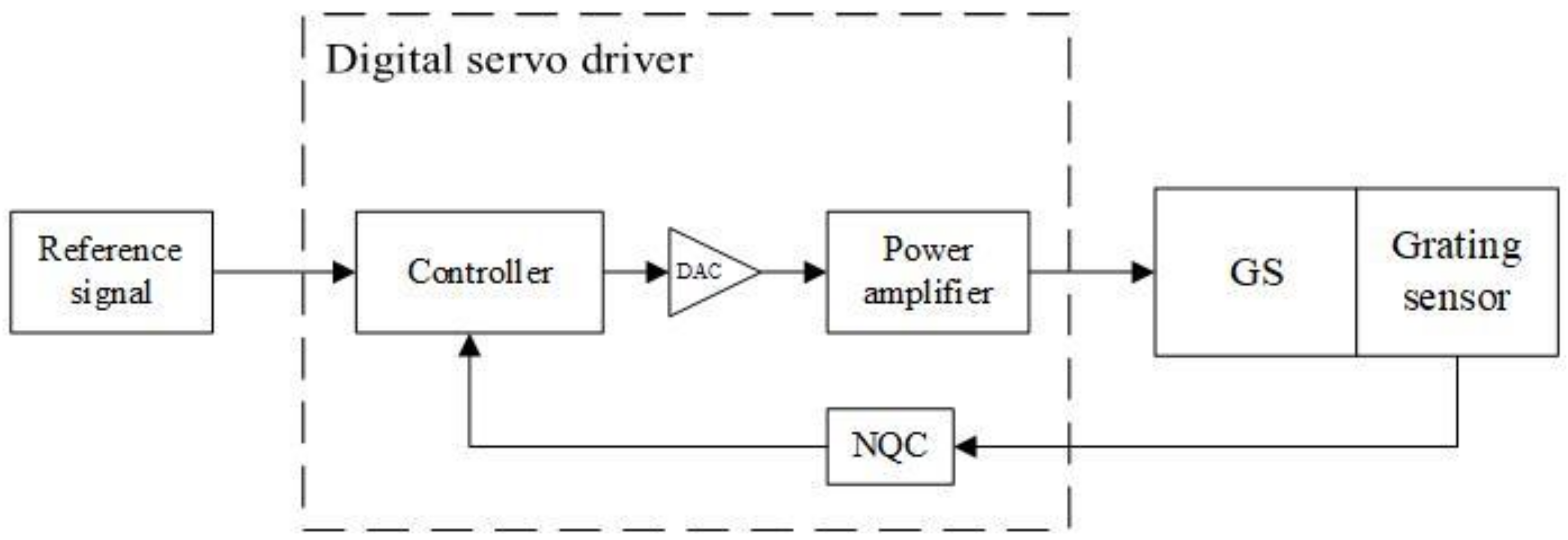
As illustrated in Figure 1, the closed-loop control system of the GS was composed of a direct-current (DC) swing motor, a mirror, a rotor position detector (grating), and a servo driver. Position signals of the rotor were sampled by a grating position sensor and then transmitted to the controller after being processed by an NQC chip, together with the reference signals produced by a host computer. After being processed by the controller, the resulting digital voltage was converted to an analogue voltage using a digital-to-analogue converter (DAC), and the driving voltage on the motor of the GS was generated through the power-amplification circuit.
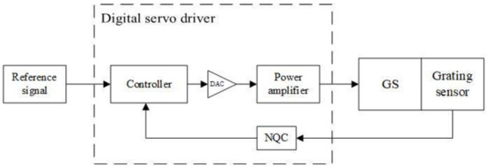
Figure 1.
Compositions of the closed-loop control system of the GS.
The dynamic Equation of the motor of the GS under an open-loop control is [8]:
where and refer to the armature voltage and current of the motor stator; and represent the resistance and inductance of the motor; and denote the inertia of the rotor and the mirror; and are the angular positions of the motor rotor and the mirror; , , and are the back electromotive force (BEF) constant, torque constant, damping coefficient, and constant of torsional rigidity, respectively.
The angular position of the mirror is equivalent to that of the rotor due to the high rigidity of the contact between the motor and the mirror of the GS used in the experiment; therefore, Equations (2) and (3) can be rewritten as:
where .
According to [14], by combining Equations (1) and (4), the open-loop transfer function of the motor is found to be:
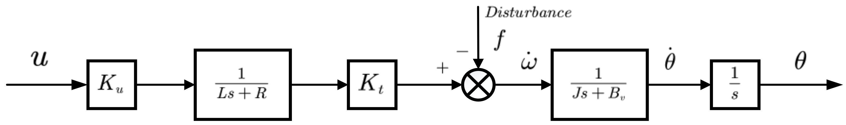
According to [15], the linear dynamic model during the running of the motor is attained, as shown in Figure 2, where is used to represent the amplification factor.
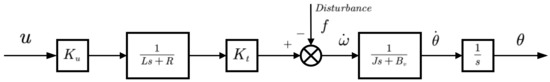
Figure 2.
The linear dynamic model pertaining to the operation of the motor.
Relative to the resistance , the inductance is negligible, so the model shown in Figure 2 can be transformed into a state-space form:
where , , , and ; represents the external disturbance.
Equation (6) is discretized through a zero-order holding. In this way, the following expression of the discrete state space is obtained:
where .
2.2. Design of the DSVC+DDC
A GS considering disturbance and parameter perturbation is expressed as follows:
where , and is controllable.
Assumption 1.
The parameter perturbation and disturbance satisfy, , where, are uncertain.
Then, Equation (8) can be rewritten as:
where represents the total external disturbance and , , in which is a constant.
The switching function is defined as:
where and , where , separately represent the expected position and expected rotational speed of the rotor at time .
The DDC is used for the online estimation of and compensation for the external disturbance. For the system shown in Equation (8), the switching function in Equation (10) is selected on the condition of meeting Assumption 1. Then, according to [16,17,18,19,20,21]:
where , , and are positive real numbers; is the estimated external disturbance at time ; and can be obtained by linear extrapolation.
The decrease of chattering is a focus of much research on sliding-mode variable-structure control, and various methods that aim at this have been proposed [22,23,24,25,26]. Eun et al. [16,18] further weakened the chattering of sliding-mode controllers during computer numerical control (CNC) machining using a saturation function. Despite this, the method does not improve the performance of such controllers when used in GSs and even degrades the dynamic performance of step-responses in some cases. Therefore, the saturation function is not used to replace the symbolic functions in Equations (11) and (12).
By combining Equations (9)–(11), it follows that:
where , and is the error of disturbance estimation.
The following can be obtained by substituting Equations (12) and (13) into :
For the convergence of Equation (14), there is a positive constant . If , then there is ; when , is established, in which .
In the case where (a)–(c) are satisfied at the same time, the closed-loop system is stable and:
When ,
,
When ,
.
(a) ;
(b) , in which is a positive constant;
(c) .
It is worth noting that determines the range of convergence of the switching function. To obtain a better control performance, generally needs to be met. Therefore, the values of and are of great importance.
2.3. Experimental Details
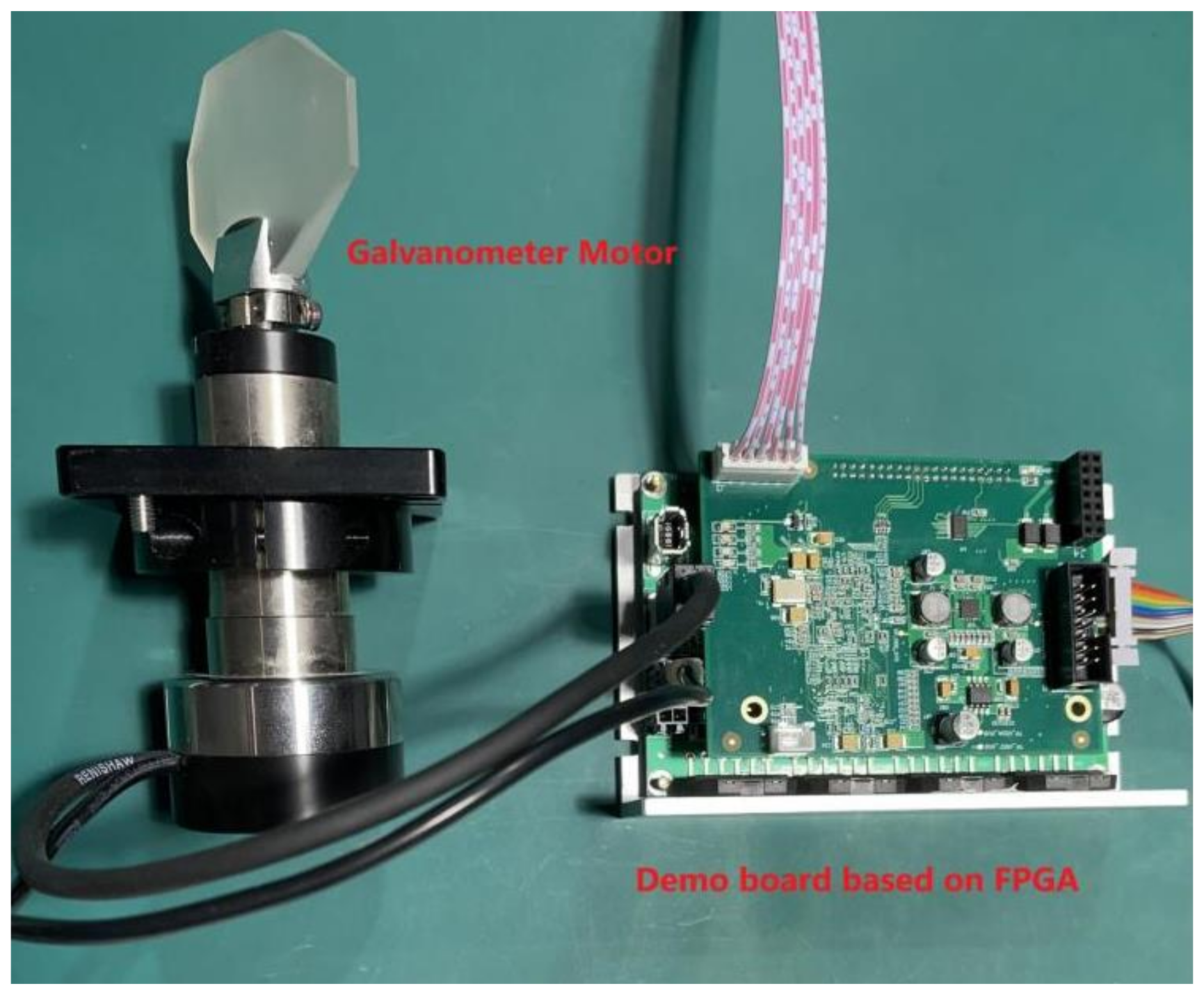
The platform (Figure 3) included a servo driver with a built-in Xilinx Spartan-6 FPGA and a GS equipped with a moving-magnetic motor with a grating position detector. The Spartan-6 FPGA had a 20-MHz crystal oscillator and multiple I/O interfaces. The DAC was a DAC8551 chip with a small volume, low power dissipation, low time delay (clock frequency: 30 MHz), and high resolution produced by Texas Instruments (TI, Dallas, Texas, USA). The power amplifier was an LM3886 chip produced by National Semiconductors (NS, Santa Clara, California, USA). The grating signals were processed using an ic-NQC chip manufactured by iC Haus, which is a 13-bit Sin/D convector with a signal calibration function. The position signals were transmitted to the computer through an RS232 serial port. Software Xilinx ISE Design Suite 14.7 with abundant IP resources was used in the experiment.

Figure 3.
The experimental platform.
The experiment was carried out indoors at 25 degrees Celsius, and the power amplifier chip in the experiment platform had been heat-dissipated (smeared with heat-dissipated silicone grease).
3. Results and Discussion
The step-response performance is an important indicator for measuring the system. In order to evaluate the effectiveness of the proposed approach, step-response experiments in 1% and 10% of the whole stroke are conducted in this section (compared with the indexes (Table 1) obtained by the traditional control method), and the steady-state error of the system is evaluated.

Table 1.
Reference performance indices for the motor of the GS.
According to the actual machining demand and [27], the reference performance indices used in the research are listed in Table 1.
Using the torque-equilibrium method to obtain the torque coefficient of the motor and the identification method for motor parameters proposed by Kaan Erkorkmaz et al. [15], the relevant parameters of the experimental platform were obtained (Table 2). (Five repeated experiments were conducted, and the results were found to be similar. Therefore, this paper takes the results of one of them as an example.)
Table 2.
Parameters of the experimental platform.
By substituting the data in Table 1 into Equation (9), the following equation is obtained:
The parameters selected for the DSVC+DDC are listed in Table 3.
Table 3.
Parameters of the DSVC+DDC.
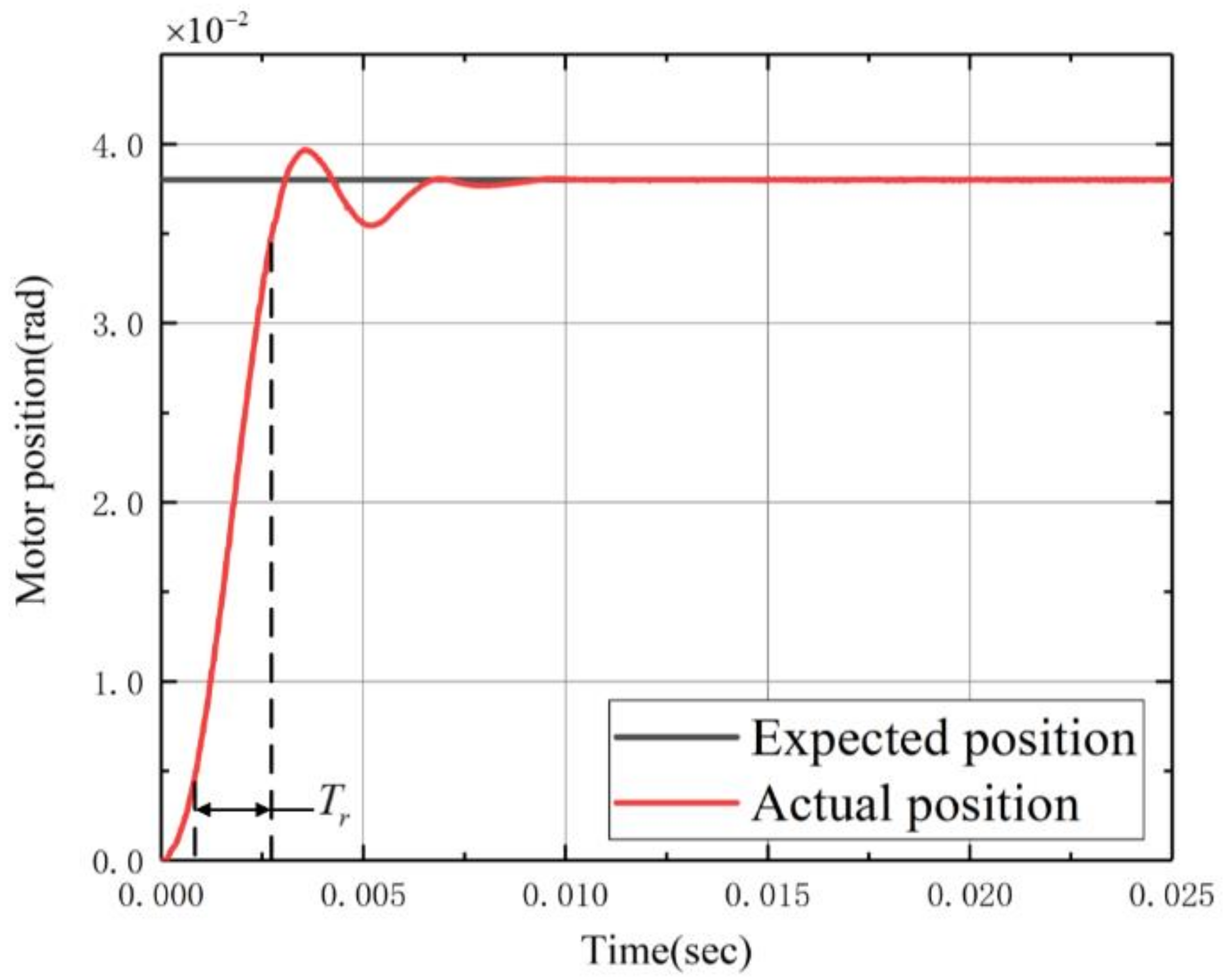
Figure 4 and Figure 5 respectively show the step-response results in 1% and 10% of the whole stroke of the GS controlled by the DSVC+DDC. The solid black line is the expected position, and the solid red line is the actual position of the rotor. The overshoot of the two red solid lines is less than 5%. Figure 4 and Table 1 show that the DSVC+DDC reduces the rise time of step-responses in 1% of the whole stroke from 1.3 ms to 1 ms (), a reduction of 23%. Figure 5 and Table 1 show that the DSVC+DDC reduces the rise time of step-responses in 10% of the whole stroke from 4.8 ms to 2 ms (), reducing it by 58%.
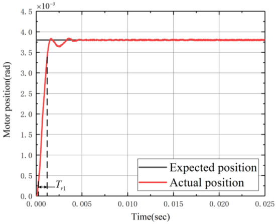
Figure 4.
Step-responses in 1% of the whole stroke (0.0038 rad).

Figure 5.
Step-responses in 10% of the whole stroke (0.038 rad).
Because small-angle swings are dominant in the operation of the motor, the steady-state error in the step-response in 1% of the whole stroke is the primary factor influencing the machining accuracy (Figure 6). As shown in Figure 6, the steady-state error of the GS small-angle position tracking is within 20 urad, that is, less than 1.2°‰, which meets the accuracy required in processing. In the experimental process, there are two main factors affecting the tracking error. One is that accurate dynamic parameters such as inertia and damping are the premise for realizing the proposed control method. The error of dynamic parameter identification results will affect the model’s precision, which will affect the control’s precision; the other factor is that the chattering phenomenon is inevitable due to the nature of the sliding mode variable structure control itself [13], which will have a negative impact on the control accuracy. To further reduce tracking errors, our future work will focus on these factors.
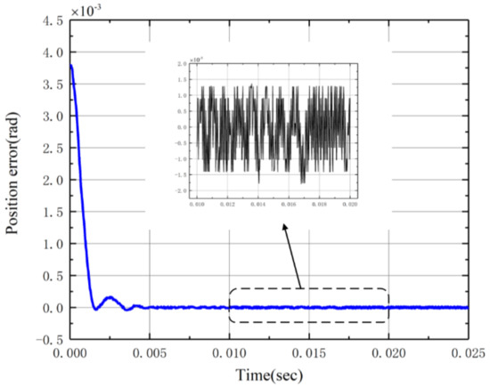
Figure 6.
Steady-state error of the step-response in 1% of the whole stroke (0.0038 rad) under the control of the DSVC+DDC.
Compared with the reference performance index (Table 1), the experimental results show that the proposed method significantly improves the step-response speed, especially for the step-responses of 10% of the whole stroke, under the condition of ensuring a certain accuracy and overshoot. Moreover, the proposed method relaxes the requirement of the known external disturbance upper bound and does not require an analogue circuit PD controller to stabilize the GS.
4. Conclusions
In this paper, a DSVC+DDC is designed to address the slow step-responses of a GS with disturbance and parameter perturbation. The proposed approach can effectively ensure the tracking accuracy and accelerate the step-response speed of the GS. The DDC can not only realize independent tuning with the sliding mode controller but also relax the traditionally assumed limit of the upper bound of external disturbance to the limit of the external disturbance change rate, reducing the difficulty of a practical application. In addition, the method also does not require an analogue circuit PD controller to stabilize the GS. In the experiment, the rise time for the step-responses in 1% and 10% of the whole stroke is separately reduced by 23% and 58% on the premise of ensuring a steady-state error of less than 20 urad and an overshoot of less than 5%. The experimental results verify the effectiveness of the proposed control method. The research is of significance to those seeking to apply the GS to laser processing equipment.
Author Contributions
G.C.: conceptualization, methodology, writing (review & editing), supervision, project administration; Y.W.: methodology, software, writing (original draft preparation), experiment, and data processing; All authors have read and agreed to the published version of the manuscript.
Funding
This research was funded by the National Key Research and Development Program of China, grant number 2017YFB1104600.
Institutional Review Board Statement
Not applicable.
Informed Consent Statement
Not applicable.
Acknowledgments
Thanks to Wenxin Liao for helpful discussions.
Conflicts of Interest
The authors declare no conflict of interest.
References
- Jiang, H.H. Development and prospect of laser machining technology application. J. Atmos. Environ. Opt. 2001, 4, 1–12. [Google Scholar]
- Sabo, D.A.; Brunner, D.; Engelmayer, A. Advantages of digital servo amplifiers for control of a galvanometer based optical scanning system. In Optical Scanning 2005; International Society for Optics and Photonics: San Diego, CA, USA, 2005; Volume 5837, pp. 113–120. [Google Scholar]
- Liu, W.; Liu, D.; Wu, J.; Chang, K.; Chou, M.; Fu, L. Precision sinusoidal tracking for galvanometer scanner with smith pre-dictor-based adaptive sliding mode control. In Proceedings of the 2016 International Automatic Control Conference (CACS), Taichung, Taiwan, 11 September 2016; pp. 100–105. [Google Scholar]
- Yoo, H.W.; Ito, S.; Verhaegen, M.; Schitter, G. Transformation-based iterative learning control for non-collocated sensing of a galvanometer scanner. In Proceedings of the 2013 European Control Conference (ECC), Zurich, Switzerland, 17 July 2013; pp. 1204–1209. [Google Scholar]
- Yoo, H.W.; Ito, S.; Schitter, G. High speed laser scanning microscopy by iterative learning control of a galvanometer scanner. Control Eng. Pract. 2016, 50, 12–21. [Google Scholar] [CrossRef]
- Ito, S.; Yoo, H.W.; Schitter, G. Noise reduction of learning control for periodic motion of galvanometer scanner. IFAC Pap. 2020, 53, 8401–8406. [Google Scholar] [CrossRef]
- Mnerie, C.A.; Preitl, S.; Duma, V.-F. Performance enhancement of galvanometer scanners using extended control structures. In Proceedings of the 2013 IEEE 8th International Symposium on Applied Computational Intelligence and Informatics (SACI), Timisoara, Romania, 23 May 2013; pp. 127–130. [Google Scholar]
- Mnerie, C.A.; Preitl, S.; Duma, V.-F. Classical PID versus predictive control solutions for a galvanometer-based scanner. In Proceedings of the 2015 IEEE 10th Jubilee International Symposium on Applied Computational Intelligence and Informatics, Timisoara, Romania, 21 May 2015; pp. 349–353. [Google Scholar]
- Pieczona, S.J.; Zollitsch, S.; Zaeh, M.F. Dynamics enhancement of galvanometer laser scanners by adaptive inverse control. In Proceedings of the 2017 IEEE International Conference on Advanced Intelligent Mechatronics (AIM), Munich, Germany, 3 July 2017; pp. 253–258. [Google Scholar]
- Zaeh, M.; Pieczona, S. Adaptive inverse control of a galvanometer scanner considering the structural dynamic behavior. CIRP Ann. 2018, 67, 385–388. [Google Scholar] [CrossRef]
- Xiao, H.; Chen, X. Multi-band beyond-Nyquist disturbance rejection on a galvanometer scanner system. In Proceedings of the 2017 IEEE International Conference on Advanced Intelligent Mechatronics (AIM), Munich, Germany, 7 July 2017; pp. 1700–1705. [Google Scholar]
- Qin, W.Y.; Guo, H.; Xu, J.Q.; Liu, L.M. High precision position control based on active disturbance rejection control for galvanometer scanner system. In Proceedings of the 2019 2nd International Conference on Electrical Machines and Systems (ICEMS 2019), Harbin, China, 11 August 2019; pp. 353–356. [Google Scholar]
- Liu, J.K.; Sun, F.C. Research and development of sliding mode variable structure control theory and algorithm. Control Theory Appl. 2007, 24, 407–418. [Google Scholar]
- Marshall, G.; Stutz, G. Handbook of Optical and Laser Scanning, 2nd ed.; CRC Press: Boca Raton, FL, USA, 2011. [Google Scholar]
- Erkorkmaz, K.; Altintas, Y. High speed CNC system design. Part II: Modeling and identification of feed drives. Int. J. Mach. Tools Manuf. 2001, 41, 1487–1509. [Google Scholar] [CrossRef]
- Eun, Y.; Kim, J.-H.; Kim, K.; Cho, D.-I. Discrete-time variable structure controller with a decoupled disturbance compensator and its application to a CNC servomechanism. IEEE Trans. Control Syst. Technol. 1999, 7, 414–423. [Google Scholar] [CrossRef]
- Zhang, K.; Su, H.; Zhuang, K.; Chu, J. Comments on discrete-time variable structure controller with a decou-pled disturbance compensator and its application to a CNC servomechanism. IEEE Trans. Control Syst. Technol. 2003, 11, 156–157. [Google Scholar] [CrossRef]
- Eun, Y.; Kim, J.-H.; Kim, K.; Dan, D.; Cho, D. Reply to Discrete-time variable structure controller with a decoupled disturbance compensator and its application to a CNC servomechanism. IEEE Trans. Control Syst. Technol. 2003, 11, 157. [Google Scholar]
- Chao, C.; Wang, W.; Zhang, W. A discrete model reference sliding mode controller with a disturbance compen-sator and its application to flight simulator. In Proceedings of the 6th Chinese Control and Decision Conference (2014 CCDC), Chongqing, China, 31 May 2014; pp. 3445–3449. [Google Scholar]
- Hou, J.; Yuan, Z.; Zhang, Q.; Wu, M. Sliding mode controller with a disturbance compensator for ce-ment combined grinding system. In Proceedings of the Chinese Automation Congress (CAC), Wuhan, China, 27 November 2015; pp. 196–201. [Google Scholar]
- Han, J.-S.; Kim, T.-I.; Park, J.-H.; Oh, T.-H.; Lee, J.-H.; Kim, S.-O.; Lee, S.-S.; Lee, S.-H.; Cho, D.-I.D. Gain selection method for robustness enhancement in sliding mode control combined with decoupled disturbance com-pensator with unknown inertia in industrial servo systems. In Proceedings of the 2017 17th International Conference on Control Automation and Systems (ICCAS), Jeju, Korea, 18 October 2017; pp. 1713–1717. [Google Scholar]
- Lee, H.; Utkin, V.I. Chattering suppression methods in sliding mode control systems. Annu. Rev. Control 2007, 31, 179–188. [Google Scholar] [CrossRef]
- Du, H.; Yu, X.; Chen, M.Z.; Li, S. Chattering-free discrete-time sliding mode control. Automatica 2016, 68, 87–91. [Google Scholar] [CrossRef]
- O’Toole, M.D.; Bouazza-Marouf, K.; Kerr, D. Chatter suppression in sliding mode control: Strategies and tuning methods. In Examples to Extremum and Variational Principles in Mechanics; Gabler: Berlin, Germany, 2010; pp. 109–116. [Google Scholar]
- Shi, S.L.; Li, J.X.; Fang, Y.M. Extended-state-observer-based chattering free sliding mode control for nonlinear sys-tems with mismatched disturbance. IEEE Access 2018, 6, 22952–22957. [Google Scholar] [CrossRef]
- Svecko, R.; Gleich, D.; Sarjas, A. The effective chattering suppression technique with adaptive su-per-twisted sliding mode controller based on the quasi-barrier function; An experimentation setup. Appl. Sci. 2020, 10, 595. [Google Scholar] [CrossRef] [Green Version]
- Hansscanner.com. Available online: http://hansscanner.com/cpzx/list_2.aspx?lcid=10 (accessed on 12 October 2021).


Publisher’s Note: MDPI stays neutral with regard to jurisdictional claims in published maps and institutional affiliations. |
© 2021 by the authors. Licensee MDPI, Basel, Switzerland. This article is an open access article distributed under the terms and conditions of the Creative Commons Attribution (CC BY) license (https://creativecommons.org/licenses/by/4.0/).