
Intelligent Active Correction Technology and Application of Tower Displacement in Arch Bridge Cable Lifting Construction


Abstract
:Featured Application
Abstract
1. Introduction
- In virtue of the Beidou GNSS measurement system and hydraulic jack active control system that have been developed rapidly in recent years, the active control technology of the concrete-filled steel tubular arch bridge tower deviation was thoroughly studied. Besides, a perfect active control theory was established.
- The paper designs and puts forward the smart active tower deviation control system to active control the horizontal displacement of the tower.
- Through the measuring instruments and smart equipment with high precision, the paper solves the tower deviation in the process of traditional cable lifting system, and reduces the impact on the precision of arch truss cantilever.
2. Analytical Model and Equations
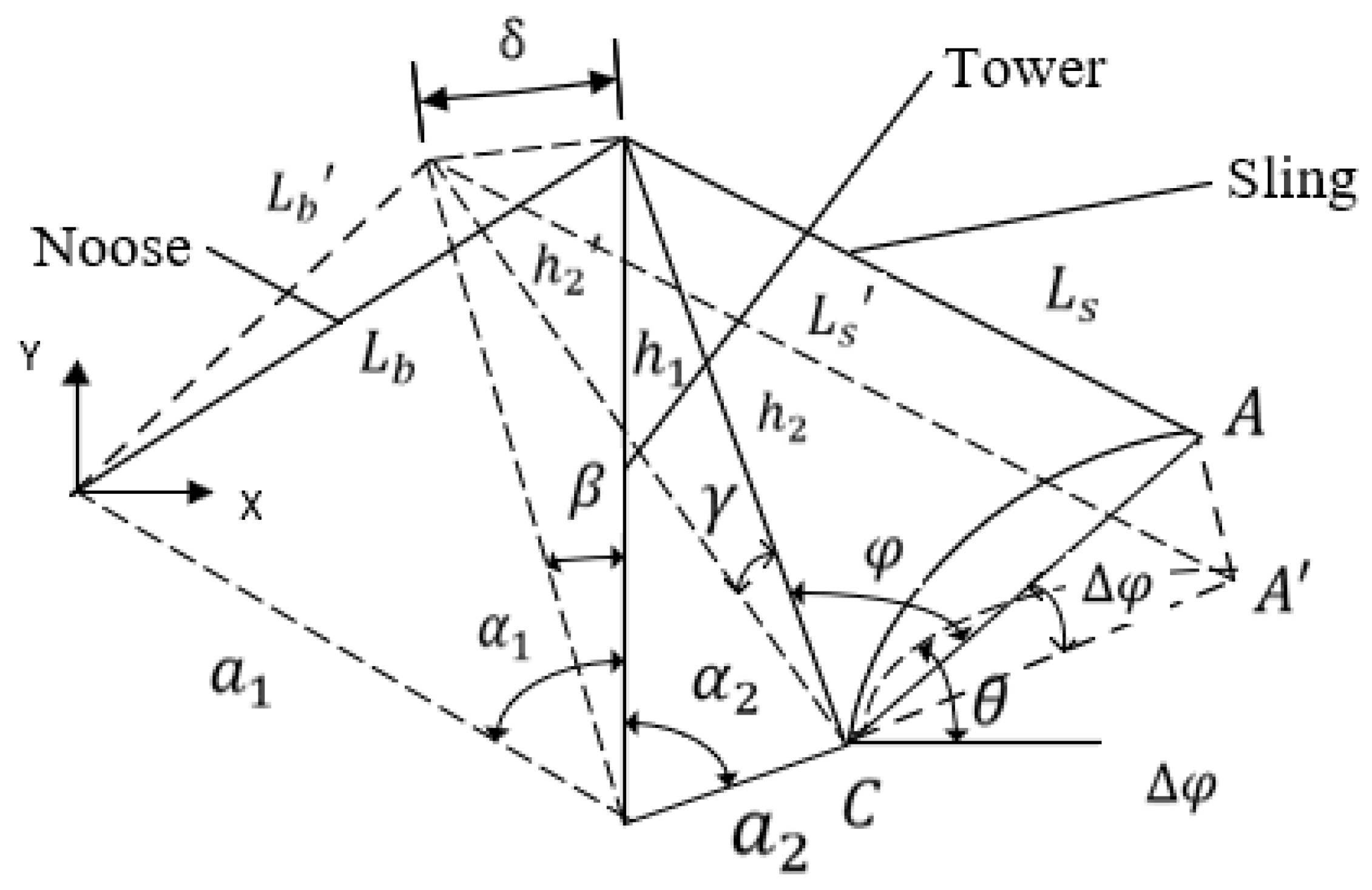
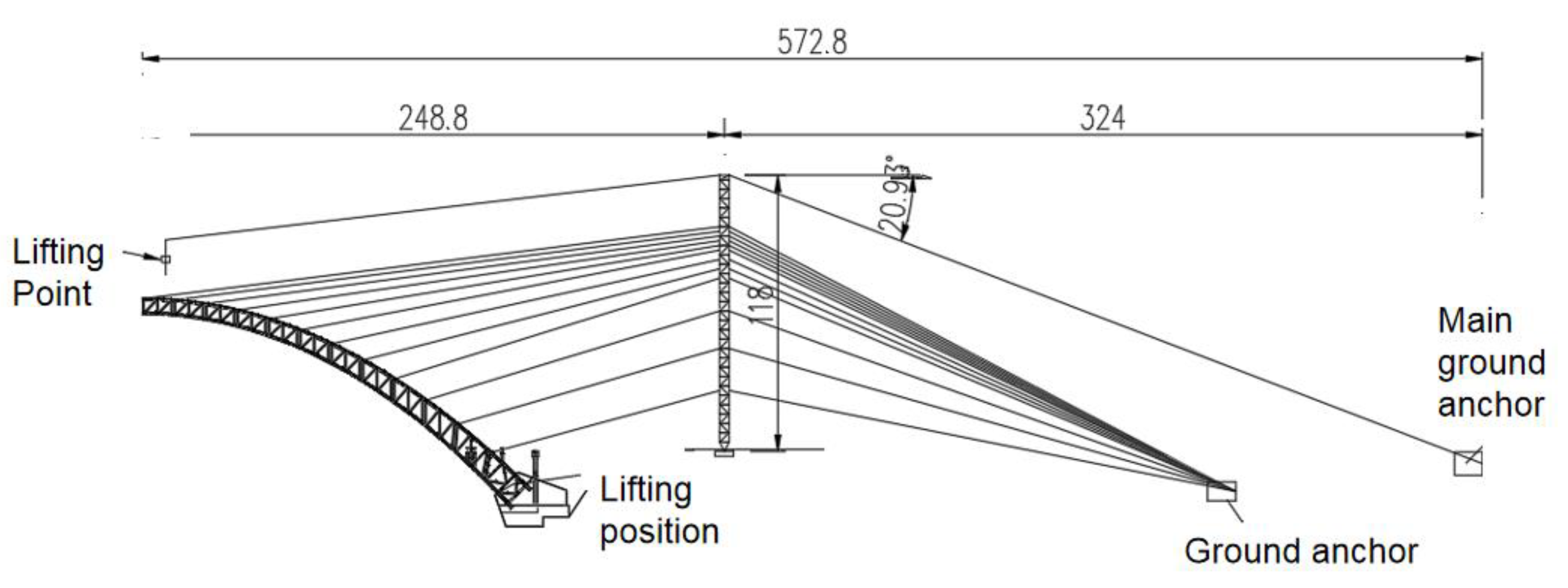
2.1. Mechanism of Tower Deviation Error Formation
2.2. Passive Control Theory
2.3. Theoretical Verification of Automatic Correction
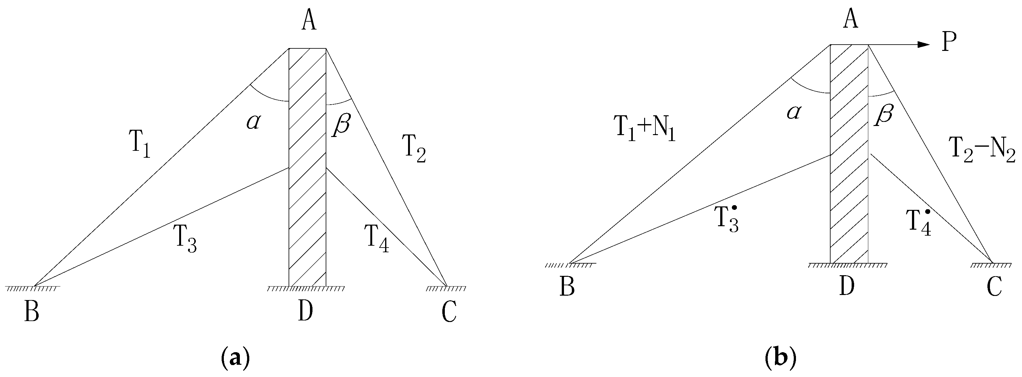
- (1)
- When Q0 = 0, N1 = N2 = 0, i.e., it is in the state of no pretension. According to Equation (16), Q = −P, indicating that the direction of Q is left.
- (2)
- When Q0 ≠ 0, N1 ≠ 0, N2 ≠ 0, the corresponding length of cantilever beam is L0. To make it satisfy the Equation (16), Q = 0, indicating that the state is the critical state for the change of Q direction.
- (3)
- When ,, if its corresponding cantilever beam length L > L0, it shows that the cantilever beam line stiffness decreases, resulting in the increased deformation, or obvious load and unload effect; let , according to Equation (16),, showing that the direction of the Q is right.
- (4)
- When ,, if its corresponding cantilever beam length , showing that the stiffness of the beam line increases, leading to the reduced deformation, thus reducing the unloading effect; make according to Equation (16),, showing that the direction of the Q is left.
3. Proposed Methodology of Monitoring
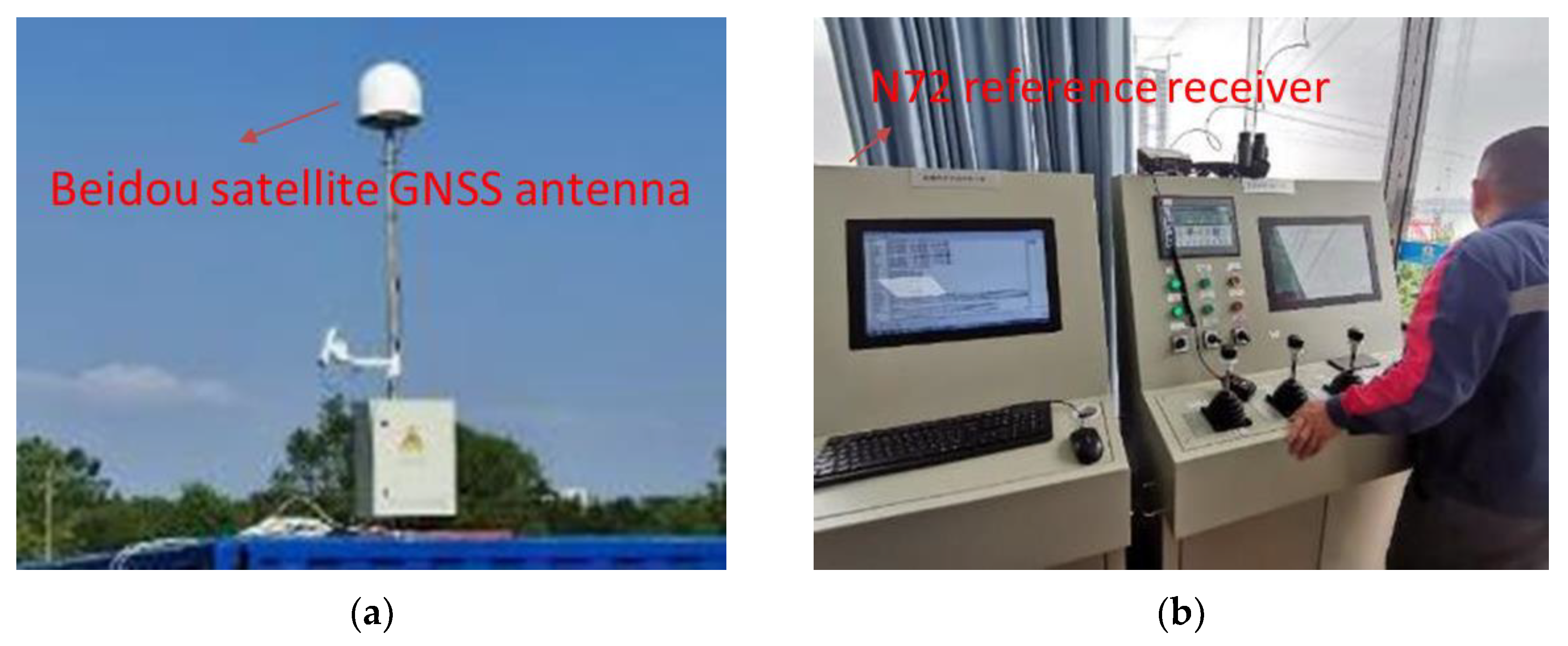
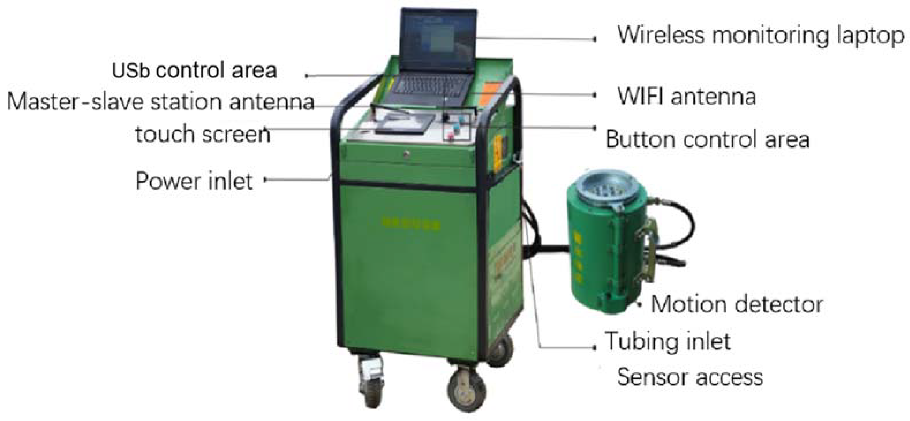
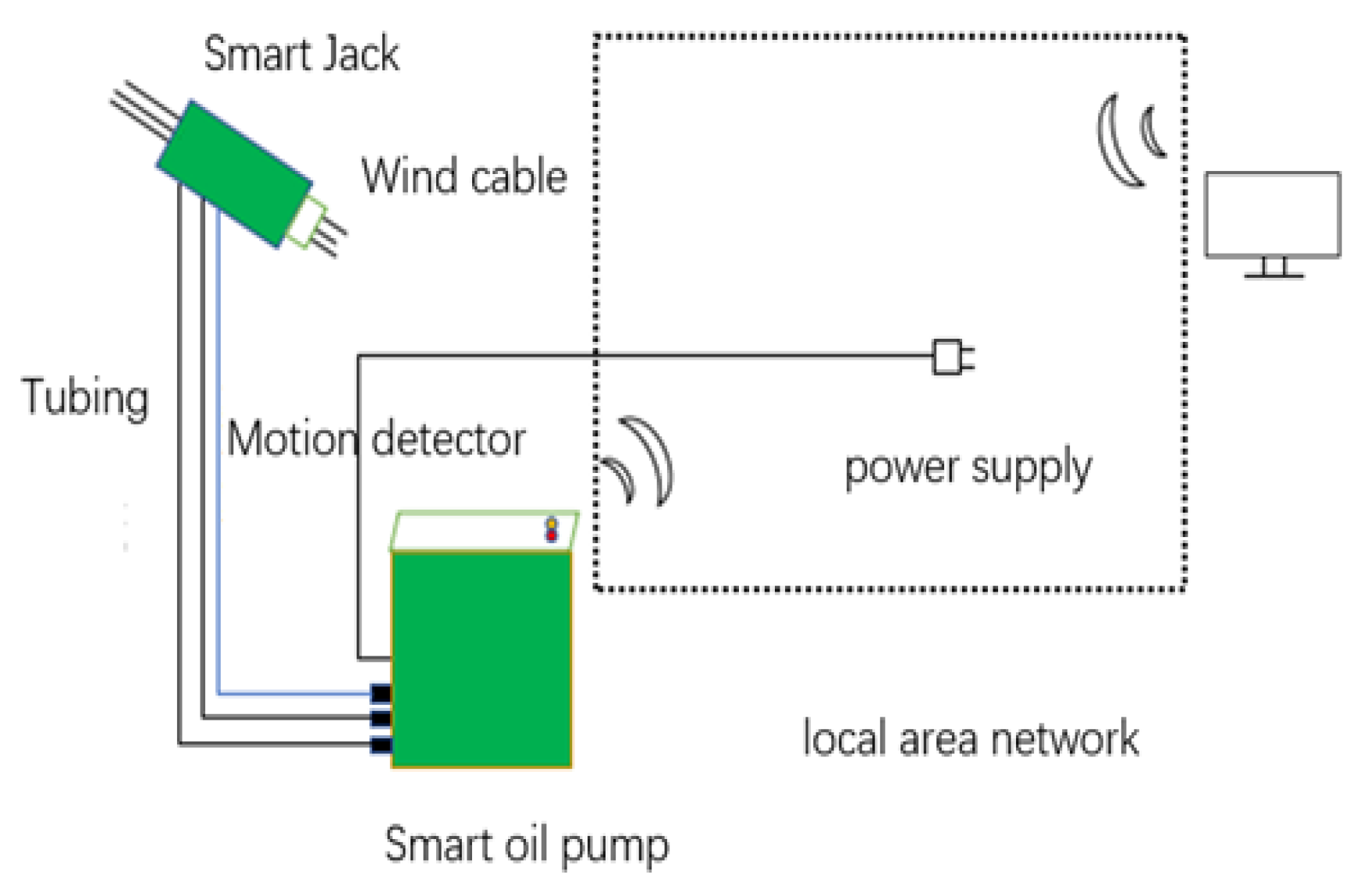
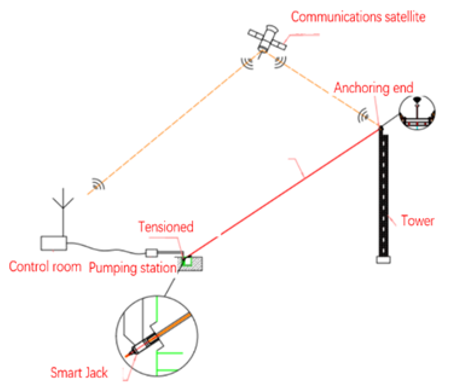
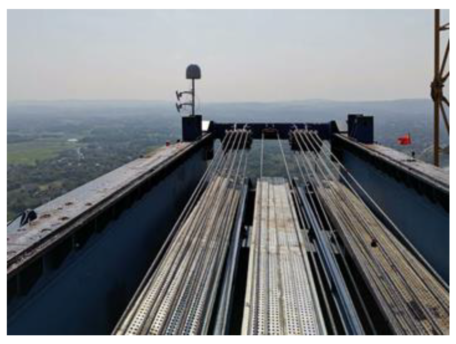
3.1. Intelligent Active Deviation Correction System
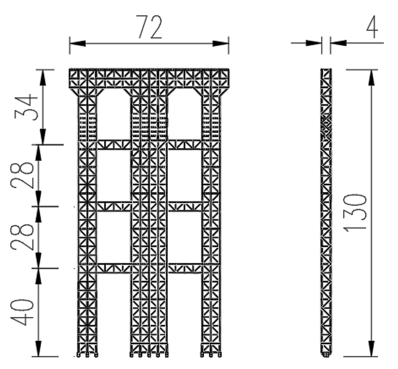
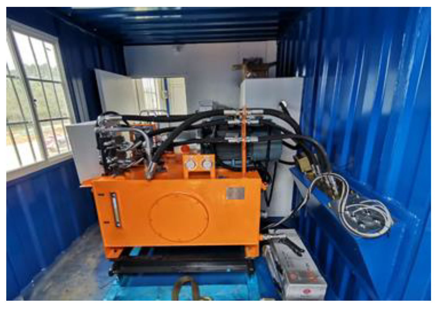
3.2. Tower Active Control System Components
3.3. The Feedback Control System
4. Proposed Methodology of Monitoring
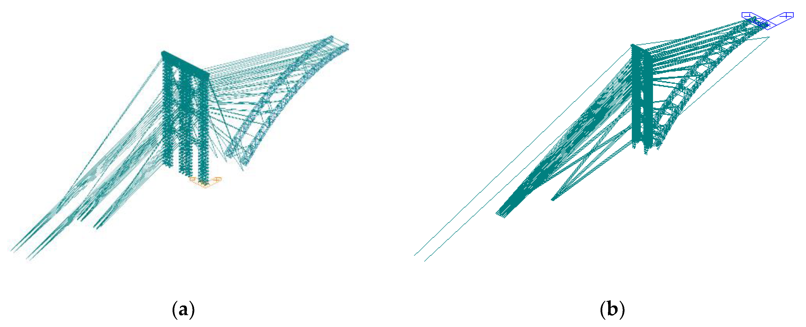
4.1. Finite Element Modeling
4.2. Deflection Displacement Analysis
4.3. Stress and Internal Force Analysis
4.4. Stability Analysis of Tower under Smart Active Control
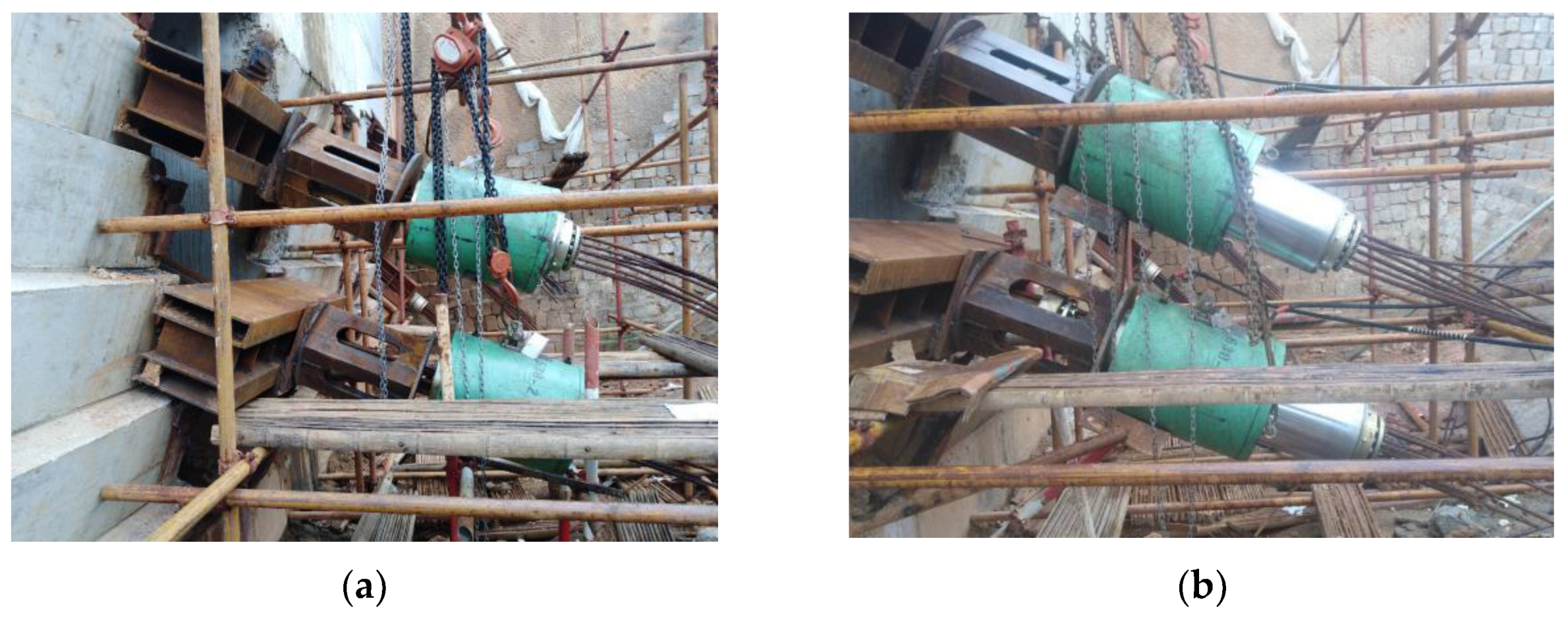
5. Engineering Application of Smart Active Control
5.1. Engineering Background
5.2. Active Control Process and Data Analysis of the Tower
6. Conclusions
- Based on the study on the tower deviation error formation mechanism in the process of cable lifting, the related formulas of the arch rib elevation change caused by the change of tower as the temporary structure state is deduced. The studies show that the arch rib hanging on it has a linkage effect due to tower stress deformation, and greatly influences the precision of arch girder suspension.
- Traditionally, the tower deviation is controlled by arranging a large number of steel strands and manually pulling the steel strands, which wastes a lot of steel strand materials and labor. Now, the cost is greatly reduced by the technology proposed in this paper.
- Under normal operation, the influence of active regulation on the stress of each component of the structure is not significant. This means that active regulation has an obvious influence on the lateral displacement of the tower, but its sensitivity to the internal force and stress of the tower is very low, and the tower is in a safe state.
- The technology, having been applied to world-class arch bridges, can actively and timely apply pressure to the tower top, correct the deviation of tower in the process of cable lifting, reduce the deviation value, and finally reduce the impact on the precision of the arch girder suspension. Furthermore, it can realize the real-time control of the tower maximum deviation within the scope of The research results explore and improve the CFST arch bridge construction technology, and provide a construction reference for the tower deviation control of the same types of bridges and more long-span CFST arch bridge with intergraded main cable and buckle. With the development of positioning technology, the measurement accuracy of tower offset will be higher, and this technology will be increasingly widely used.
Author Contributions
Funding
Institutional Review Board Statement
Informed Consent Statement
Data Availability Statement
Conflicts of Interest
References
- Chen, B.; Huang, Q. Study on the design of 600 m span concrete arch bridge. J. China Foreign Highw. 2006, 26, 80–82. [Google Scholar] [CrossRef]
- Salonga, J.; Gauvreau, P. Comparative study of the proportions, form, and efficiency of concrete arch bridges. J. Bridge. Eng. 2014, 19, 04013010. [Google Scholar] [CrossRef]
- Nazmy, A.S. Stability and load-carrying capacity of three-dimensional long-span steel arch bridges. Comput. Struct. 1997, 65, 857–868. [Google Scholar] [CrossRef]
- Kwon, S.H.; Kim, T.H.; Kim, Y.Y.; Kim, J.K. Long-term behavior of square concrete-filled steel tubular columns under axial service loads. Mag. Concr. Res. 2007, 59, 53–68. [Google Scholar] [CrossRef]
- Wang, Y.; Geng, Y.; Ranzi, G.; Zhang, S. Time-dependent behavior of expansive concrete-filled steel tubular columns. J. Constr. Steel Res. 2011, 67, 471–483. [Google Scholar] [CrossRef]
- Chen, B.; Su, J.L.; Lin, S.; Chen, G.; Zhuang, Y.; Tabatabai, H. Development and application of concrete arch bridges in China. J. Asian Concr. Fed. 2017, 3, 12–19. [Google Scholar] [CrossRef]
- Li, S.; Ou, J.; Wang, J.; Gao, X.; Yang, C. Level 2 safety evaluation of concrete-filled steel tubular arch bridges incorporating structural health monitoring and inspection information based on China bridge standards. Struct Control Health Monit. 2019, 26, e2303. [Google Scholar] [CrossRef]
- Zheng, J.; Wang, J. Concrete-filled steel tube arch bridges in China. Engineering 2018, 4, 143–155. [Google Scholar] [CrossRef]
- John, J.S. Construction of the Hoover Bam Bypass. Concr. Int. 2011, 33, 30–35. [Google Scholar]
- Chen, B.C.; Wang, T.L. Overview of concrete filled steel tube arch bridges in China. Pract. Period. Struct. Des. Constr. 2009, 14, 70–80. [Google Scholar] [CrossRef]
- Wei, J.; Chen, B. Application and research advancement of long span concrete arch bridges abroad. World Bridge. 2009, 2, 4–8. [Google Scholar] [CrossRef]
- Yang, Z.; Han, Y. The application of active control technology for the displacement of a high tower and the top of the tower with a buckle combination. Highway 2020, 65, 171–175. [Google Scholar]
- Lin, C.; Zhang, J.; Qin, R. Review of concrete confined concrete filled steel tubular arch rib. J. China Foreign Highw. 2004, 24, 54–58. [Google Scholar]
- Xie, X.; Qin, R.; Peng, W.; Deng, Z. Theoretical analysis of creep and shrinkage effects in SRC arch bridge. Eng. Sci. 2001, 3, 80–84. [Google Scholar] [CrossRef]
- Yao, C.; Li, Y. Study of alignment control for concrete filled steel tube arch bridge. J. Highw. Transp. Res. Dev. 2006, 23, 65–69. [Google Scholar] [CrossRef]
- Zhang, K.; Liu, S.; He, Y.; Yi, G. Dynamic control of the arch rib alignment for long-span concrete-filled steel-tube arch bridge. J. Wuhan Transp. Univ. 2000, 24, 1–4. [Google Scholar] [CrossRef]
- Guo, Q.; Li, Z.; Zhang, S. Study on digital tensioning technique in prestressed concrete structure. China Civil. Eng. J. 2004, 37, 13–17. [Google Scholar] [CrossRef]
- Qian, H.; Jia, Y.; Lin, J.; Zhao, X. Research and development of innovative intelligent pre-stressed stretching equipment. Process. Autom. Instrum. 2009, 30, 49–51. [Google Scholar] [CrossRef]
- Liang, X.; Wu, T.; Liu, D. A study on comparative experiments between prestressed intelligent tensioning and prestressed traditional tensioning. Highway 2012, 4, 144–146. [Google Scholar] [CrossRef]
- Chen, B. Study on construction of concrete-filled steel tube arch bridge. Bridge. Constr. 2002, 3, 55–59. [Google Scholar] [CrossRef]
- Liao, Q.; Xu, J.; Li, W. Application of prestressed intelligent tension system in construction of bridges. Technol. Highw. Transp. 2005, 4, 102–105. [Google Scholar] [CrossRef]
- Zhen, J.; Xu, F.; Tang, B. The construction simulation calculation method of steel arch truss erecting by Jacks with inclined Hooks for Yongjiang Bridge in Yongning, Guangxi. In Proceedings of the Bridge and Structural Engineering Society of China Highway Society 1966 Symposium on Bridges (CHTS 1996), Beijing, China, 15–19 December 1996; pp. 214–228. [Google Scholar]
- Feng, M.; Ye, Q. Intelligent control of concrete filled steel tubular arch bridge construction process. Zhongwai Highway 2020, 6, 119–123. [Google Scholar] [CrossRef]
- Pan, D.; Deng, N. Analysis of the pouring sequence of super large span CFST arch bridge based on intelligent active load regulation technology. Highway 2020, 65, 130–137. [Google Scholar]
- Yu, J. GNSS and RTS technologies based structural health monitoring of bridges. Acta Geod. Cartogr. Sin. 2015, 44, 1177. [Google Scholar] [CrossRef]
- He, Y.; Miao, Y.; Liu, H. Based on Beidou/GPS precise displacement monitoring technology in the application of the bridge monitoring. J. Yunnan Univ. 2016, 38, 35–39. [Google Scholar]
- Wang, J.; Wang, L. The application of Beidou satellite positioning technology in slope displacement monitoring. Railw. Constr. 2020, 60, 85–88. [Google Scholar] [CrossRef]
- Zheng, J.; Deng, N.; Yao, X.; Wang, J.; Han, Y.; Yang, Z. Research on active control of tower displacement based on GNSS displacement measurement system and hydraulic control system. Highway 2018, 63, 97–99. [Google Scholar]
- Qin, S. Unstressed state control method for process control of structure formed by stages. Eng. Sci. 2009, 11, 72–78. [Google Scholar] [CrossRef]
- Han, Y.; Du, H.; Qin, D.; Luo, X.; Xie, W.; Zheng, J. Research and development of key technologies and key difficulties in the construction of No.3 Bridge in PingNan. Highway 2019, 10, 140–146. [Google Scholar]
- Ernst, H.J. The Modulus of Elasticity of Cables Taking in Account the Catenary Action. Der Bauing. 1965, 40, 52–55. [Google Scholar]
- Meng, S.; Yang, R.; Wang, J. A new formula for cable force measurement of tied arch bridge considering the influence of flexural stiffness accurately. Highw. Traffic Sci. Technol. 2008, 6, 87–98. [Google Scholar]
- Wu, W.; Chen, C. Tension determination for suspenders of arch bridge based on multiple vibration measurements concentrated at one end. Measurement 2018, 123, 254–269. [Google Scholar] [CrossRef]
- Bonopera, M.; Chang, K.-C.; Chen, C.-C.; Lin, T.-K.; Tullini, N. Bending tests for the structural safety assessment of space truss members. Int. J. Space Structures 2018, 33, 138–149. [Google Scholar] [CrossRef]
- Giovanni Rebecchi, N.T. Estimate of the axial force in slender beams with unknown boundary conditions using one flexural mode shape. J. Soundand Vib. 2013, 332, 4122–4135. [Google Scholar] [CrossRef]
- Yi, T.H.; Li, H.N.; Gu, M. Experimental assessment of high-rate GPS receivers for deformation monitoring of bridge. Measurement 2013, 46, 420–432. [Google Scholar] [CrossRef]


| Research Content | Studies | Research Flaws |
|---|---|---|
| Smart tower deviation control systems Smart tower deviation control systems | In 2020, Feng [23] introduced a GNSS-based active control technology for the longitudinal displacement of the tower top. | Through theoretical analysis, the feasibility of the smart tower deviation control system was verified, but no actual engineering application was carried out. |
| In 2020, Pan [24] used the intelligent active load regulation technology to adjust the arch rib deformation during the concrete-filled steel tube pouring process | Pan [24] used intelligent active load regulation technology to control the deformation of the arch rib during the pouring process, but did not consider the deformation of the tower. | |
| The methods of analysing and measurement | Since 2015, Yu [25] and He et al. [26] studied the application of Beidou/GPS high-precision monitoring in bridge engineering, showing that Beidou has a stable and reliable dynamic monitoring. | Failure to apply satellite monitoring methods to the bridge. |
| Wang J. and Wang L. [27] conducted a precision calibration test on the Beidou monitoring system, and the results show that the horizontal displacement measurement accuracy is within 2 mm, and the settlement measurement accuracy is within 5 mm, proving that the accuracy of automatic satellite monitoring is consistent with the manual monitoring of total station, and it is not easily affected by the environment. | It proves that the satellite monitoring system replaces manual measurement with higher accuracy and can meet construction needs, but it is not used for bridge monitoring. |
| Project | Number | Conditions | Load Combination |
|---|---|---|---|
| Matan Hongshui He Bridge | Condition 1 | Normal hanging arch ribs | Cable action, self-weighting, buckle load, 6 levels of vertical wind, cable air rope initial tension |
| Condition 2 | Normal hanging arch ribs under the action of active control force | Cable action, self-weighting, buckle load, 6 levels of vertical wind, cable initial tension, active control force | |
| Pingnan Third Bridge | Condition 1 | Normal hanging arch ribs | Cable action, self-weighting, buckle load, 6 levels of vertical wind, cable air rope initial tension |
| Condition 2 | Normal hanging arch ribs under the action of active control force | Cable action, self-weighting, buckle load, 6 levels of vertical wind, cable initial tension, active control force |
| Project | Direction | Condition 1 | Condition 2 | Regulation Rate of Change (%) |
|---|---|---|---|---|
| Matan Hongshui He Bridge | Horizontal (mm) | 153.00 | 18.10 | −88.17 |
| Vertical (mm) | −48.80 | −51.08 | 4.67 | |
| Pingnan Third Bridge | Horizontal (mm) | 185.22 | 17.07 | 90.78 |
| Vertical d(mm) | −83.39 | −78.78 | 5.50 |
| Project | Result | Condition 1 | Condition 2 | Regulation Rate of Change (%) |
|---|---|---|---|---|
| Matan Hongshui He Bridge | Column steel pipe maximum stress (MPa) | 118.90 | 117.40 | 1.28 |
| Tower top structure Maximum stress (MPa) | 122.10 | 122.70 | 0.49 | |
| Buckle anchoring maximum stress (MPa) | 88.60 | 89.50 | 1.01 | |
| Tower top shaft force (kN) | 219.70 | 337.80 | 34.96 | |
| Base of the tower shaft force (kN) | 2679.50 | 2870.10 | 6.64 | |
| Tower top bending moment (kN·m) | 290.72 | 282.90 | 2.76 | |
| Bottom of the tower bending moment (kN·m) | 63.90 | 62.90 | 1.59 | |
| Pingnan Third Bridge | Maximum stress of column steel pipe (MPa) | 182.10 | 193.9 | 6.48 |
| Maximum stress of tower structure (MPa) | 60.20 | 61.9 | 2.82 | |
| Maximum stress of tower web (MPa) | 62.11 | 64.00 | 3.04 | |
| Internal force at the bottom of the tower (kN) | 3679.20 | 3769.10 | 2.44 |
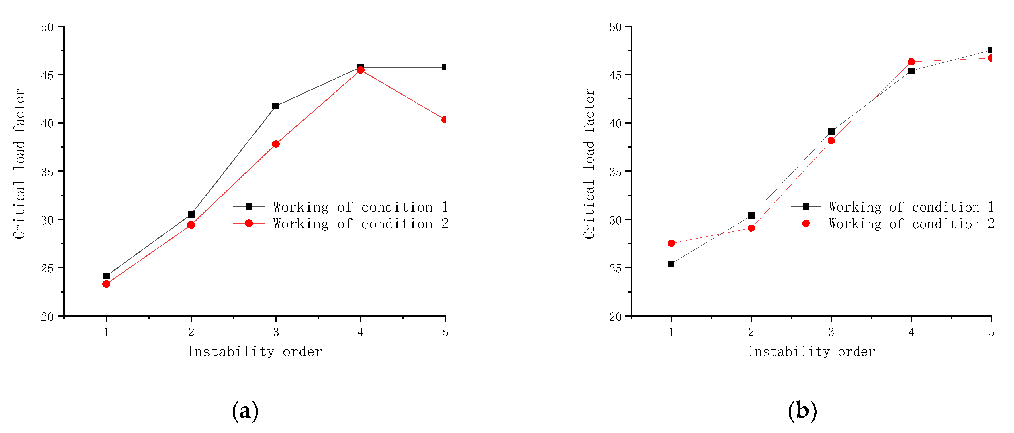
| Project | Instability Order | Condition 1 Critical Load Factor | Condition 2 Critical Load Factor | Regulatory Change Rate (%) |
|---|---|---|---|---|
| Matan Hongshui He Bridge | 1 | 24.15 | 23.32 | 3.44 |
| 2 | 30.53 | 29.44 | 3.57 | |
| 3 | 41.76 | 37.81 | 9.46 | |
| 4 | 45.77 | 45.47 | 0.66 | |
| 5 | 45.77 | 40.33 | 11.89 | |
| Pingnan Third Bridge | 1 | 25.42 | 27.54 | 8.34 |
| 2 | 30.40 | 29.11 | 4.24 | |
| 3 | 39.12 | 38.17 | 2.43 | |
| 4 | 45.41 | 46.33 | 2.03 | |
| 5 | 47.54 | 46.71 | 1.75 |
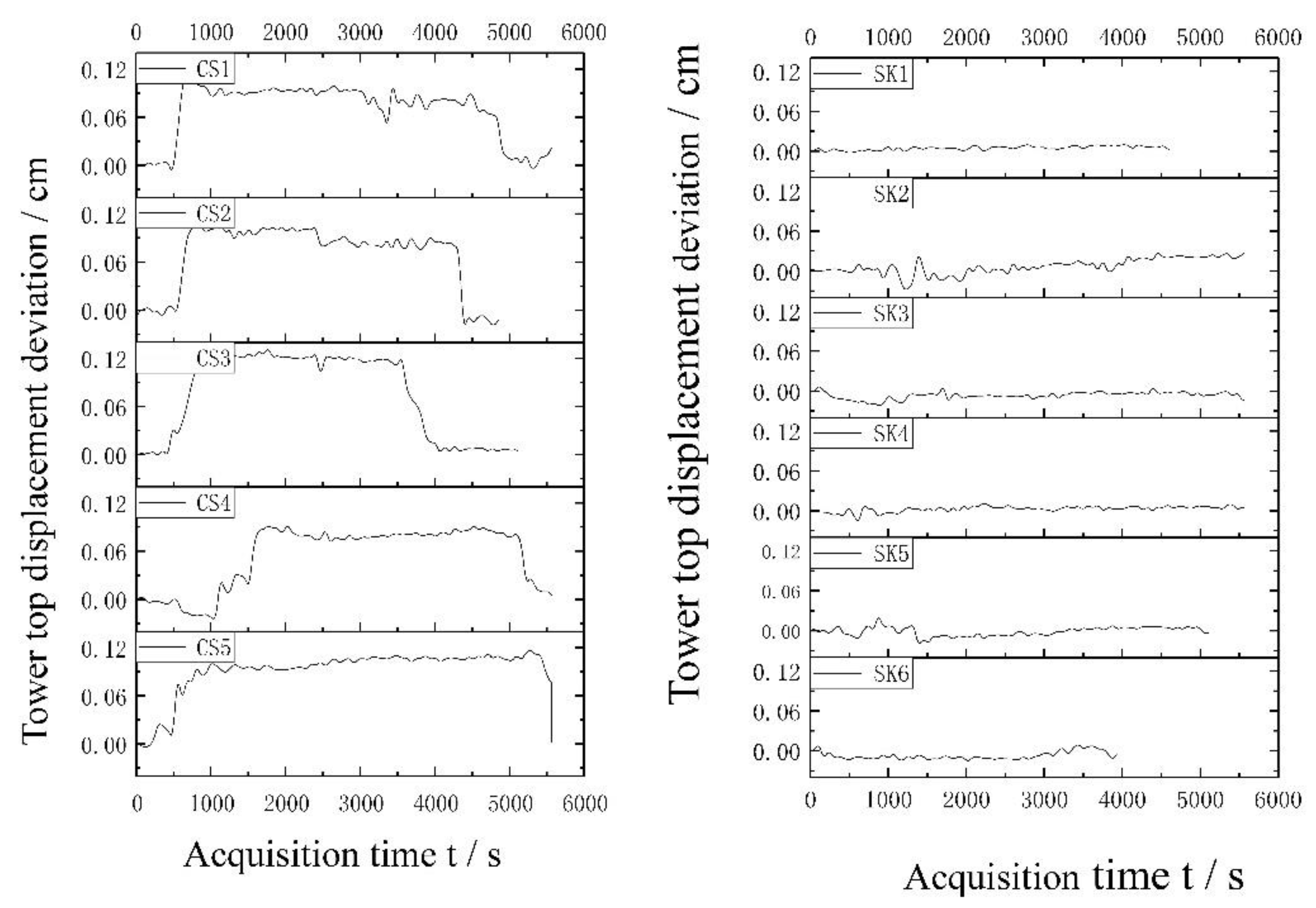
| Construction Group 1 | Unregulated Segment (South Bank) | Construction Group 3 | Regulated Segment (North Bank) |
|---|---|---|---|
| CS1 | Section 1 # of Matan Hongshui He Bridge | TK1 | Section 1 # of Matan Hongshui He Bridge |
| CS2 | Section 5 # of Matan Hongshui He Bridge | TK2 | Section 5 # of Matan Hongshui He Bridge |
| CS3 | Section 6 # of Matan Hongshui He Bridge | TK3 | Section 6 # of Matan Hongshui He Bridge |
| CS4 | Section 1 # of Pingnan Third Bridge | TK4 | Section 1 # of Pingnan Third Bridge |
| CS5 | Section 5 # of Pingnan Third Bridge | TK5 | Section 5 # of Pingnan Third Bridge |
Publisher’s Note: MDPI stays neutral with regard to jurisdictional claims in published maps and institutional affiliations. |
© 2021 by the authors. Licensee MDPI, Basel, Switzerland. This article is an open access article distributed under the terms and conditions of the Creative Commons Attribution (CC BY) license (https://creativecommons.org/licenses/by/4.0/).
Share and Cite
Deng, N.; Yu, M.; Yao, X. Intelligent Active Correction Technology and Application of Tower Displacement in Arch Bridge Cable Lifting Construction. Appl. Sci. 2021, 11, 9808. https://doi.org/10.3390/app11219808
Deng N, Yu M, Yao X. Intelligent Active Correction Technology and Application of Tower Displacement in Arch Bridge Cable Lifting Construction. Applied Sciences. 2021; 11(21):9808. https://doi.org/10.3390/app11219808
Chicago/Turabian StyleDeng, Nianchun, Mengsheng Yu, and Xinyu Yao. 2021. "Intelligent Active Correction Technology and Application of Tower Displacement in Arch Bridge Cable Lifting Construction" Applied Sciences 11, no. 21: 9808. https://doi.org/10.3390/app11219808
APA StyleDeng, N., Yu, M., & Yao, X. (2021). Intelligent Active Correction Technology and Application of Tower Displacement in Arch Bridge Cable Lifting Construction. Applied Sciences, 11(21), 9808. https://doi.org/10.3390/app11219808