Article

A New Coupling Method for Accurate Measurement of Pedicle Screw Electrical Properties for Surgical Procedures

by
Pedro Fonseca
1,2,*,
Márcio Fagundes Goethel
1,
Ricardo Sebastião
1,3,
Manoela Vieira Sousa
1,3,4,
João Paulo Vilas-Boas
1,3,4,
Miguel Velhote Correia
1,2,5 and
Manuel Gutierres
1,6
1
Porto Biomechanics Laboratory, University of Porto (LABIOMEP-UP), 4200-450 Porto, Portugal
2
Faculty of Engineering, University of Porto (FEUP), 4200-465 Porto, Portugal
3
Faculty of Sport, University of Porto (FADEUP), 4200-450 Porto, Portugal
4
Centre of Research, Education, Innovation and Intervention in Sport, Faculty of Sport, University of Porto (CIFI2D), 4200-450 Porto, Portugal
5
Institute for Systems and Computer Engineering, Technology and Science (INESCTEC), 4200-465 Porto, Portugal
6
Faculty of Medicine, University of Porto (FMUP), 4200-319 Porto, Portugal
*
Author to whom correspondence should be addressed.
Appl. Sci. 2021, 11(21), 9861; https://doi.org/10.3390/app11219861
Submission received: 27 September 2021 / Revised: 17 October 2021 / Accepted: 19 October 2021 / Published: 22 October 2021
(This article belongs to the Section Biomedical Engineering)

Abstract

:
The objective of this study is to present a new coupling method in order to measure the electrical properties of titanium alloy pedicle screws used in spinal surgery and to compare it with other common methods of measurement. An experimental setup was devised to test the electrical resistance of two specimens of pedicle screws using four methods for coupling the sensing leads, including the use of multimeter probes, alligator clips, wrapped wires and encapsulation with thermo-retractable sleeves. The electrical resistance of the pedicle screw under testing was measured at a current of 10 mA for each coupling method, and the results compared. Our findings show that although widely used in electrical analysis, the alligator clips do not perform as well as the other methods, such as simple wrapping of wires around the screw or the direct application of multimeter probes. The use of thermo-retractable sleeves provides the lowest resistance and inter-quartile range and is closer to the tabled values for the screw’s titanium alloy. Additionally, only this method allows the measurement of identical resistivity values between different screw models manufactured with the same titanium alloy. We then concluded that the use of wrapped wires encapsulated with thermo-retractable sleeves allow more accurate measurements of the pedicle screw’s electrical properties.

1. Introduction

During spinal surgery requiring the instrumentation of the vertebral column, there is a non-negligible risk of damaging the nervous structures [1]. In order to avoid such undesired outcomes, intraoperative neuromonitoring (IONM) techniques may be used to guarantee safety of procedures. Several methods are available, including intraoperative fluoroscopy, trans-cranial stimulation, somatosensory evoked potentials and motor evoked potentials [2].
In the specific case of intrapedicular instrumentation of the lumbar or thoracic vertebras, the electrical stimulation of either the pedicle track or the pedicle screw is a possible IONM approach. This method is based on the principle that a medial pedicle breach will provide a low-resistance path through which a given electrical current may flow and stimulate a compound muscle potential of the muscles enervated by the neighbouring nerve roots [3]. The electrical current stimulation threshold that would indicate a correct insertion was initially proposed to be 7.0 or 10.0 mA, depending if the pedicle track or the pedicle screw was stimulated [3]. However, other authors have reported wider ranges [4,5,6,7]. While some systematic reviews have identified the current thresholds associated to higher sensitivities of this IONM method [8,9,10], there is no complete explanation yet with respect to the high levels of heterogeneity and lack of agreement between studies on the best current stimulation threshold.
This is a multifactorial issue caused by the multiple situations that may alter the normal nerve stimulation, which not only includes patient intrinsic aspects such as compressed nerve roots [11] but also extrinsic ones, such as the properties of the pedicle screw [12]. Although pedicle screws have been extensively characterized and analysed in terms of their biomechanical [13] and mechanical properties [14,15], the study of their electrical properties is still scarce. The available studies have shown that electrical properties of screws can differ due to factors such as the manufacturer [16], shaft’s hollowness [12] or the application of special coatings such as hydroxyapatite [17]. However, these studies used different coupling techniques to establish a contact between the pedicle screw and the measuring devices’ leads, either by using unipolar probes [16], alligator clips [12,18,19] or conductive epoxy glues [16]. Since contact resistance is a well-known issue that can increase measured electrical resistance [20] and other contributing factors for increased electrical resistance can also be present in each of the above mentioned methods, the identification or development of an adequate coupling method is necessary. Such coupling is the first requisite to enable accurate standardized measurements and the development of appropriate sensing apparatus for laboratory-based studies of the pedicle screw’s electrical properties.
Therefore, the objective of this study is to (i) present the development of a new coupling method between the pedicle screw and the measuring device’s leads by means of thermo-retractable sleeves; (ii) to analyse its measurement accuracy by comparing it with other common measurement methods and the tabled electrical properties of the titanium alloy used to manufacture the pedicle screw; and (iii) to determine if it presents the necessary discriminant ability to measure the titanium alloy electrical resistivity from two different pedicle screws.

2. Materials and Methods

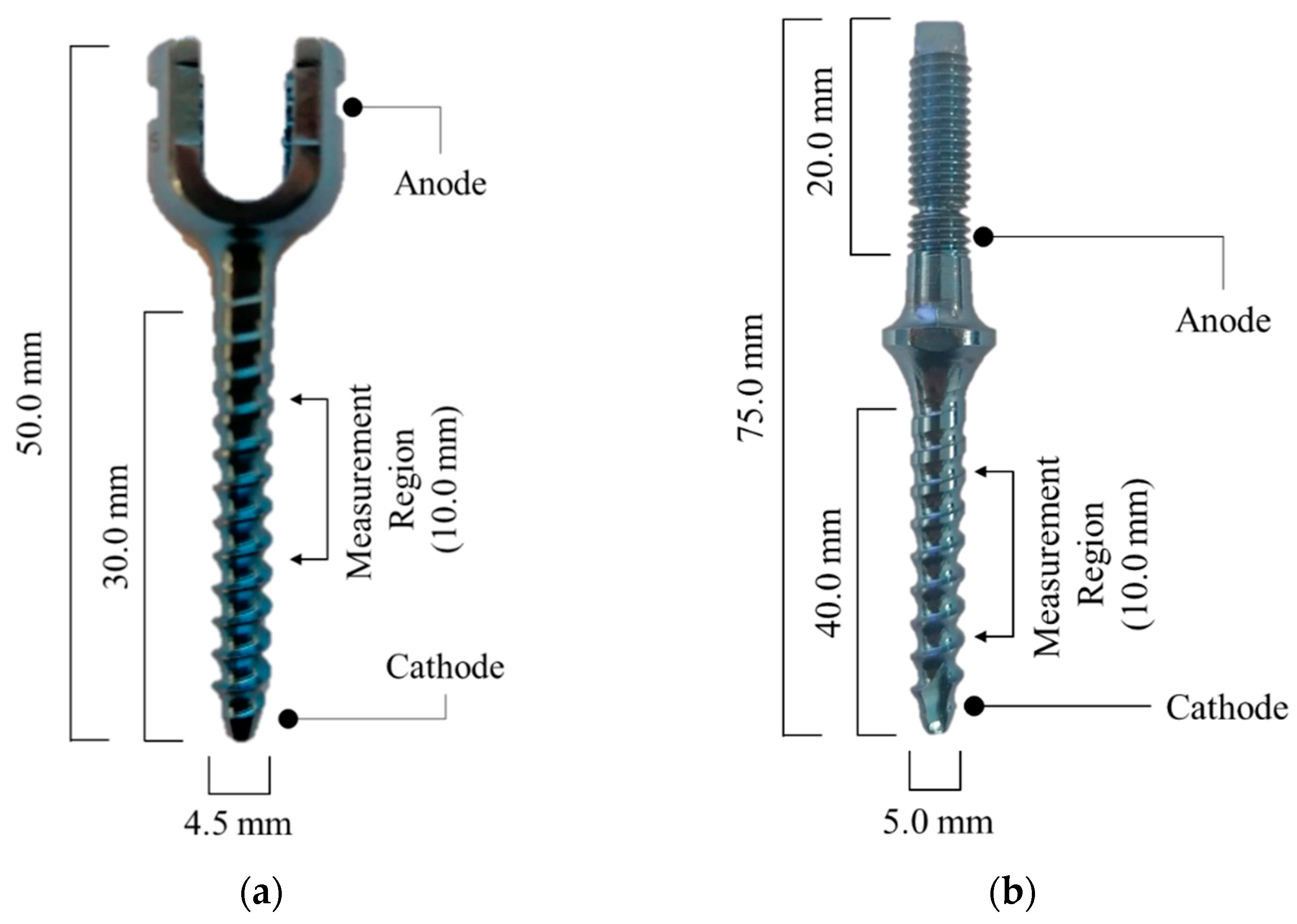
2.1. Testing Samples

Two solid uniaxial titanium-aluminium-vanadium alloy (Ti-6Al-4V; approximated weight proportion: 90% Ti, 6% Al, 4% V) pedicle screws, one from the Spinelock and another from the Spinecall sets manufactured by Spine Implantes (São Paulo, Brazil) according to the ASTM F136 standard, were selected for this study. Both screws presented a blue colour resulting from an anodization process at 27 V. The Spinelock screw had 4.5 mm diameter and 50.0 mm length from the top of the crown to the tip of the threaded body, while the Spinecall screw was 5.0 mm in diameter and 75.0 mm length. A representation of both screws and a summary of their physical dimensions is available in Figure 1. Both screws were cleaned with isopropyl alcohol in order to remove any grease or dirt before measurements of their electrical resistance.

2.2. Testing Setup

A testing circuit was established with a BK Precision 1672 (BK Precision, CA, USA) power supply connected in series with the pedicle screw under analysis, an Agilent U1251B (Agilent, CA, USA) ammeter and a 1.0 kΩ variable resistance. This resistance acted as a trimmer that allowed the fine tuning of the desired current value flowing through the circuit. Additionally, in order to measure the voltage drop caused by the pedicle screw, an Agilent 34405A (Agilent, CA, USA) was applied in parallel to the screw and connected to its measurement region. A representation of this circuit can be observed in Figure 2.
With the Spinelock screw, the power supply anode was connected to one of the crown’s faces and the cathode to the screw’s tip. When testing the Spinecall, the cathode was also connected to the screw’s tip, but the anode was connected to the most distal portion of the locking thread segment. These power connection points are described in Figure 1.

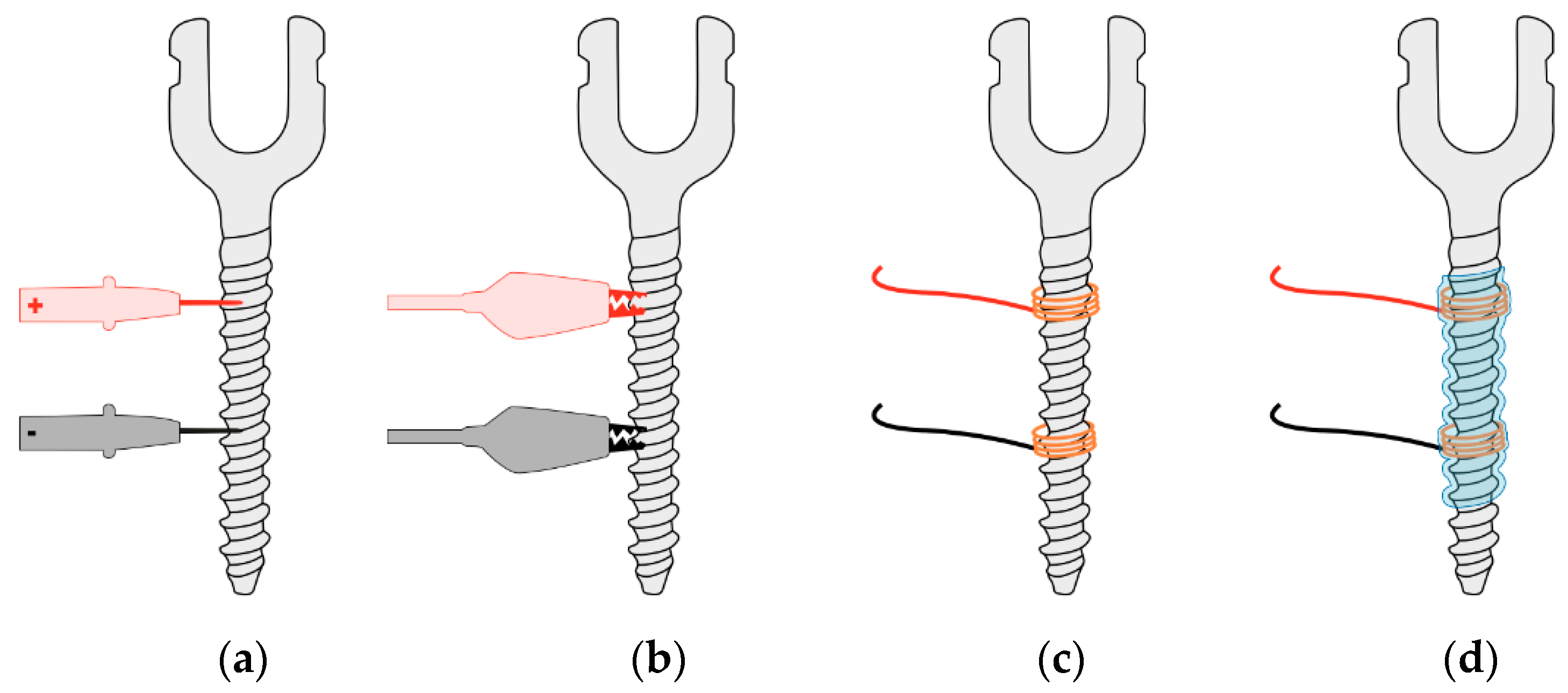
2.3. Coupling Methods

The voltage across a 10 mm length section around the midpoint of the threaded body of each screw was measured with four different methods of coupling, including the use of the following: (a) a pair of multimeter probes manually held in contact with the screw (PROBE); (b) a pair of 35.0 mm alligator clips (CLIPS); (c) a pair of insulated copper stranded wires with 0.07 mm2 cross-section area wrapped around the screw’s body and held in place with hot glue to form a tight contact ring (WRAP); and (d) the insertion of the pedicle screw with the contact rings used in (c) but with no glue application into a transparent thermo-retractable sleeve and the application of heat to conform it (CAPSULE). A representation of these coupling methods is illustrated in Figure 3.

2.4. Data Collection Procedures

All measurements were performed with the power supply set at 5 V and a constant current output of 10 mA. This current was confirmed before each measurement and adjusted with the trimmer if needed. Between measurements, the voltmeter probes and alligator clips were removed and reapplied during the PROBE and CLIPS conditions, while the connection leads were disconnected and connected to the voltmeter during the WRAP and CAPSULE conditions. A total of 50 trials were collected for each coupling method on a single day at a room temperature of 25 °C. The resistance of the pedicle screw was then calculated according to Ohm’s Law.
The resistivity was also calculated in order to allow the comparison between pedicle screws since the specimens used in this study presented different diameters; therefore, the resistance values were expected to differ as well. The calculation of resistivity also allows the comparison of results with those reported by other authors. Resistivity was calculated using the following equation:
ρ = R · A l
where ρ is the resistivity in Ω·m, R denotes the resistance in Ohm, A denotes the screw’s cross-sectional area in square meters and l denotes the length between the contact points of the measuring leads in meters.

2.5. Statistical Analysis
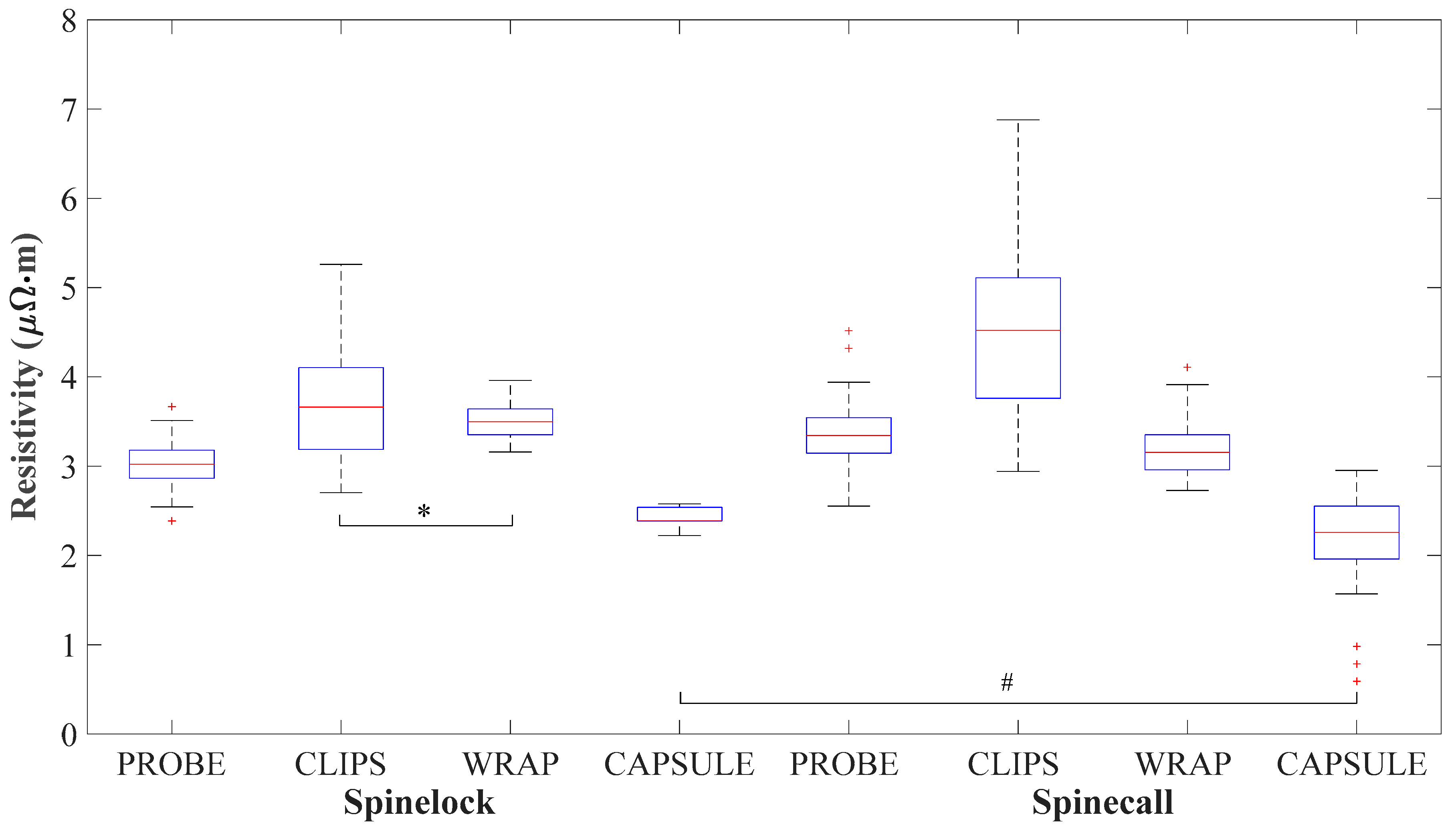
After checking data distribution conditions using the Kolmogorov–Smirnov normality test, a Kruskal–Wallis test was conducted to test the null hypothesis that there is no difference between coupling methods by using the previously calculated electrical resistance and resistivity. Follow-up Mann–Whitney comparisons were performed with the significance level adjustment according to the Bonferroni correction. The resulting effect sizes (r) were calculated by using Rosenthal’s formula [21] and interpreted according to Cohen [22] as large (r = 0.5), medium (r = 0.3) and small (r = 0.1). All statistical tests were performed using IBM SPSS Statistics, version 27 (IBM, New York, NY, USA), with a significance level of α = 0.05.

3. Results

When measuring the resistance of the Spinelock screw, the CLIPS method returned the highest median and inter-quartile range (2.302 (0.576)), followed by the WRAP (2.199 (0.184)), PROBE (1.899 (0.198)) and CAPSULE (1.502 (0.096)) methods. During the resistance measurement of the Spinecall screw, CLIPS (2.302 (0.691)) also presented the highest electrical resistance and CAPSULE (1.150 (0.327)) the lowest. However, for this screw, the second and third highest resistances were recorded with PROBE (1.702 (0.202)) and WRAP (1.606 (0.222)), respectively.
The measured voltage, current, calculated electrical resistance and resistivity for each coupling method and pedicle screw are presented in Table 1.
Statistically significant differences were found between measuring methods on the Spinelock (χ2(3) = 145.570, p < 0.001) and Spinecall (χ2(3) = 141.367, p < 0.001) screws, both in terms of resistance and resistivity.
The results from the sequential Mann–Whitney tests comparing the different coupling methods for each pedicle screw are depicted in Table 2. Since the statistical results from the electrical resistance and resistivity were the same, a single table is presented.
Statistically significant differences were found between all coupling methods (p < 0.001) but not between CLIPS and WRAP (p = 0.882) on the Spinelock screw. In both screws, the larger effect sizes were observed when comparing the CAPSULE with any other method. In the Spinelock screw, this occurs when comparing CAPSULE with WRAP (r = 0.863), CLIPS (r = 0.863) and PROBE (r = 0.827), while the larger effect sizes occurred between CAPSULE and CLIPS (r = 0.855), PROBE (r = 0.833) and WRAP (r = 0.800) for the Spinecall screw.
When comparing the resistivity of each pedicle screw, measured with the same method (i.e., Spinelock CLIPS vs. Spinecall CLIPS), differences are found between screws, as depicted in Table 3. The only exception is found when comparing the resistivity obtained from CAPSULE (p = 0.019) where no difference between screws was identified, although presenting a small effect size.
A graphical representation of the electrical resistivity values and differences between methods can be observed in Figure 4.

4. Discussion

The electrical properties of pedicle screws have been reported in the scientific literature as measured with different coupling methods. However, not all methods are the same when ensuring an adequate coupling between the pedicle screw and measuring leads. The actual resistance of the screw is a recurrent concern and suspected of being one the causes of false-negatives in intra-operative electrical stimulation [19]; thus, the use of adequate coupling methods while characterizing the pedicle screws is of utmost importance.
This study explored a selection of coupling methods to measure the electrical properties of pedicle screws and tested it on two screw models of the same material and anodization process. The electrical resistivity of the Ti-6Al-4V alloy is known to be 1.71 μΩ·m [23], meaning that the expected resistance considering the screws’ diameter and measurement region length is 1.075 mΩ for the Spinelock and 0.871 mΩ for the Spinecall. Since electrical resistance and resistivity are intrinsic to the material and, as such, should remain constant across different coupling methods, a method that provides results closer to these tabled values should be the most adequate for pedicle screw electrical characterization.
The application of multimeter probes to the pedicle screw is probably the easiest method for measuring its electrical properties, and the comparatively small probe diameter allows accurate placement over a given section of the screw. While this method provided the second lowest resistance measurements on the Spinelock screw, there was a need to apply a considerable amount of force to ensure contact between the probes and the pedicle screw. If an insufficient amount of force was applied, the voltmeter values would not stabilize. This is probably the result of the reduced contact area between the probe and the screw due to both structures presenting a round surface.
Alternatively, alligator clips are commonly reported as the chosen coupling method in this type of study [12,18,19]. The jagged shape of the clip’s teeth and the bracing force provided by the spring allow an apparent good grip to the screw’ threads. However, the gripping force exerted will vary according to the screw’s diameter, and the teeth may not conform to the thread’s shape, resulting in reduced contact surfaces and hence higher electrical resistance. The intrinsic instability of this coupling was also noted by Zyss, Bernat, Wolff, Riouallon and Pascal-Moussellard [18], who reported that rotating the screw under the clips or increasing its pressure resulted in electrical resistance changes. These assertions are corroborated by our results, with the overall increase in resistance and the higher inter-quartile range due to the reapplication of the clips or rotation of the screws, being observed in both screws specimens. These attributes make the CLIPS a poorly reliable coupling method for resistance measurements.
If the contact area and the conformation to the shape of the screw are critical aspects of a good coupling, wrapping a thigh conductive ring around its shaft should provide better results. Indeed, a significantly lower median resistance and inter-quartile range was observed at the Spinecall screw when using this method but not at the Spinelock screw, which did not provide significant differences with the CLIPS methods. This different outcome between screws may be related to specimen preparation, which could have resulted in a less tight conductive ring in the Spinelock screw and, therefore, a lower contact area. Similarly, more robust methods such as the use of conductive epoxy [16] are available, which transforms any contact imperfection between the conductive ring and the screw into a conductive medium while keeping the leads in place. However, such materials are often expensive, and removal is not practical.
The CAPSULE method is very similar to WRAP, as the coupling is performed by a conductive ring. However, instead of using a glue to keep the ring in place, a thermo-retractable sleeve was used. This allows the application of an almost uniform pressure around all sides of the conductive ring, thus ensuring a more homogenous large contact surface. This coupling also better mimics real use conditions where the pedicle screw will be tightly surrounded by tissue during its electrical stimulation. With this coupling, a lower resistance and resistivity was achieved in both screw models, and although they are not as low as the reported for Ti-6Al-4V alloys [23], it is the method with the closest results, thus being the most accurate coupling tested in this study.
The differences with respect to the tabled electrical properties of Ti-6Al-4V may be due to testing conditions, namely ambient temperature, surface features and measuring equipment characteristics. However, the study of Davis, Tadlock, Bernbeck, Fung and Molinares [17], using more complex apparatus in a material testing laboratory, showed resistivity values identical to those of CAPSULE. Screw resistivity and the accuracy of its measurement are also important for understanding the effect of the anodization as it may influence the overall resistance of the screw [19]. In this study, only the CAPSULE method allowed the measurement of identical resistivity values between pedicle screw models. This is particularly significant, as this is a material dependent property, and both pedicle screw specimens were manufactured with the same titanium alloy and anodization process. This demonstrates that the CAPSULE, when compared to the other coupling methods of this study, is the only method accurate enough to ensure the measurement of pedicle screw electrical properties.
It should be noted that the results of this study present some limitations. First, these methods were not tested with pedicle screws from different manufacturers or with different models, such as poliaxial screws, which have been reported to have higher electrical resistance due to the mobile crown [19]. While the specimens used in this study were submitted to the same anodization procedure, it was not verified if they had an identical layer of titanium oxide, which can also contribute to different resistivity. Additionally, it is worthy to mention that this study was a laboratory-based development of a coupling method to measure resistance of pedicle screws. However, once inserted into living tissue, other interactions may happen; therefore, the study of the electrical properties on animal models should be considered as a next step for further characterization of pedicle screws.

5. Conclusions

The results of this study have shown that couplings with a larger surface area and adequate stabilization will allow more accurate measurements. The methods presented in this study do not exhaust the measuring possibilities insofar as other methods may be devised. For instance, the machining of matching nuts, with adequate conductive properties and lead connections, may be a more robust and reproducible method for analysing the pedicle screw’s electrical properties. However, the methods presented here can be easily reproduced in most laboratory settings.
The use of thermo-retractable sleeves to keep the contact leads in contact with the pedicle screw may be used in further studies of the electrical characterization of screws where small differences in resistance need to be measured.

Author Contributions

P.F. and M.F.G. designed and developed the testing setup; P.F. performed data collection, initial writing and manuscript editing; M.F.G. analysed results and cooperated in the discussion section; R.S. performed data analysis and the statistical procedures; M.V.S. managed data, performed calculations and created figures and tables; J.P.V.-B. and M.V.C. provided experimental equipment and reviewed the testing protocol; M.G. analysed results and provided a review of the discussion. All authors have read and approved the study. All authors have read and agreed to the published version of the manuscript.

Funding

This research received no external funding.

Institutional Review Board Statement

Ethical review and approval was not required for this study, as no humans or animals were subjected to any experimental testing.

Informed Consent Statement

Not applicable.

Data Availability Statement

The data collected in this study are available upon request to the corresponding author.

Acknowledgments

The authors would like to express their gratitude to Juliana Soares for the illustrations in this article.

Conflicts of Interest

The pedicle screws used in this study were provided by Spine Implantes (Brazil) at no cost for research purposes, and the article processing charges were also supported by this company. This entity had no role in the design of the study; in the collection, analyses or interpretation of data; in the writing of the manuscript; or in the decision to publish the results.

References

  1. Clavijo, C.F.; Scott, B.K. Intraoperative Neuromonitoring for Specific Neurosurgical Procedures. In Neurocritical Care Management of the Neurosurgical Patient; Kumar, M., Kofke, W.A., Levine, J.M., Schuster, J., Eds.; Elsevier: London, UK, 2018; pp. 59–70. [Google Scholar] [CrossRef]
  2. Fonseca, P.; Goethel, M.; Vilas-Boas, J.P.; Gutierres, M.; Correia, M.V. A Bibliometric analysis of intraoperative neuromonitoring in spine surgery. World Neurosurgery 2021, 154, 3–12. [Google Scholar] [CrossRef] [PubMed]
  3. Calancie, B.; Madsen, P.; Lebwohl, N. Stimulus-evoked EMG monitoring during transpedicular lumbosacral spine instrumentation. Initial clinical results. Spine 1994, 19, 2780–2786. [Google Scholar] [CrossRef] [PubMed]
  4. Min, W.K.; Na, S.B.; Jang, J.A. Accuracy of thoracic pedicle screw placement using freehand technique and triggered EMG in adolescent idiopathic scoliosis: Is it different between concave and convex side? J. Orthop. Surg. 2018, 26, 2309499018784975. [Google Scholar] [CrossRef] [PubMed] [Green Version]
  5. Ravindra, V.M.; Kalra, R.R.; Dailey, A.T. Electromyography stimulation compared with intraoperative O-arm imaging for evaluating pedicle screw breaches in lumbar spine surgery: A prospective analysis of 1006 screws in 164 patients. Spine J. 2019, 19, 206–211. [Google Scholar] [CrossRef] [PubMed]
  6. Reidy, D.P.; Houlden, D.; Nolan, P.C.; Kim, M.; Finkelstein, J.A. Evaluation of electromyographic monitoring during insertion of thoracic pedicle screws. J. Bone Joint Surg. Br. 2001, 83, 1009–1014. [Google Scholar] [CrossRef]
  7. Parker, S.L.; Amin, A.G.; Farber, S.H.; McGirt, M.J.; Sciubba, D.M.; Wolinsky, J.P.; Bydon, A.; Gokaslan, Z.L.; Witham, T.F. Ability of electromyographic monitoring to determine the presence of malpositioned pedicle screws in the lumbosacral spine: Analysis of 2450 consecutively placed screws. J. Neurosurg. Spine 2011, 15, 130–135. [Google Scholar] [CrossRef]
  8. Lee, C.H.; Kim, H.W.; Kim, H.R.; Lee, C.Y.; Kim, J.H.; Sala, F. Can triggered electromyography thresholds assure accurate pedicle screw placements? A systematic review and meta-analysis of diagnostic test accuracy. Clin. Neurophysiol. 2015, 126, 2019–2025. [Google Scholar] [CrossRef]
  9. Mikula, A.L.; Williams, S.K.; Anderson, P.A. The use of intraoperative triggered electromyography to detect misplaced pedicle screws: A systematic review and meta-analysis. J. Neurosurg. Spine 2016, 24, 624–638. [Google Scholar] [CrossRef]
  10. Öner, A.; Ely, C.G.; Hermsmeyer, J.T.; Norvell, D.C. Effectiveness of EMG use in pedicle screw placement for thoracic spinal deformities. Evid. Based Spine Care J. 2012, 3, 35–43. [Google Scholar] [CrossRef] [PubMed] [Green Version]
  11. Limbrick, D.D., Jr.; Wright, N.M. Verification of nerve root decompression during minimally-invasive lumbar microdiskectomy: A practical application of surgeon-driven evoked EMG. Minim. Invasive Neurosurg. 2005, 48, 273–277. [Google Scholar] [CrossRef] [PubMed]
  12. Wang, H.; Liao, X.; Ma, X.; Li, C.; Han, J.; Zhou, Y. Solid and hollow pedicle screws affect the electrical resistance: A potential source of error with stimulus-evoked electromyography. Indian J. Orthop. 2013, 47, 352–356. [Google Scholar] [CrossRef] [PubMed]
  13. Liu, M.-Y.; Tsai, T.-T.; Lai, P.-L.; Hsieh, M.-K.; Chen, L.-H.; Tai, C.-L. Biomechanical comparison of pedicle screw fixation strength in synthetic bones: Effects of screw shape, core/thread profile and cement augmentation. PLoS ONE 2020, 15, e0229328. [Google Scholar] [CrossRef]
  14. Kubiak, A.J.; Lindqvist-Jones, K.; Dearn, K.D.; Shepherd, D.E.T. Comparison of the mechanical properties of two designs of polyaxial pedicle screw. Eng. Fail. Anal. 2019, 95, 96–106. [Google Scholar] [CrossRef]
  15. Rosa, G.L.; Clienti, C.; Mineo, R.; Audenino, A. Experimental analysis of pedicle screws. Procedia Struct. Integr. 2016, 2, 1244–1251. [Google Scholar] [CrossRef] [Green Version]
  16. Limthongkul, W.; Savage, J.; Nenonene, E.K.; Karaikovic, E.E. Evaluation of the intrinsic properties of pedicle screws: Do diamater, manufacturing and screw design affect resistance and/or resistivity. Bosn. J. Basic Med. Sci. 2009, 9, S77–S82. [Google Scholar] [CrossRef] [PubMed] [Green Version]
  17. Davis, T.T.; Tadlock, S.; Bernbeck, J.; Fung, D.A.; Molinares, D.M. Can triggered electromyography be used to evaluate pedicle screw placement in hydroxyapatite-coated screws: An electrical examination. J. Clin. Neurophysiol. 2014, 31, 138–142. [Google Scholar] [CrossRef] [PubMed]
  18. Zyss, J.; Bernat, I.; Wolff, S.; Riouallon, G.; Pascal-Moussellard, H. Limitations and pitfalls of the pedicle screw testing monitoring technique: An in vivo and in vitro study. Neurophysiol. Clin. 2017, 47, 393–403. [Google Scholar] [CrossRef] [PubMed]
  19. Anderson, D.G.; Wierzbowski, L.R.; Schwartz, D.M.; Hilibrand, A.S.; Vaccaro, A.R.; Albert, T.J. Pedicle screws with high electrical resistance: A potential source of error with stimulus-evoked EMG. Spine 2002, 27, 1577–1581. [Google Scholar] [CrossRef] [PubMed]
  20. Ksiazkiewicz, A.; Dombek, G.; Nowak, K. Change in electric contact resistance of low-voltage relays affected by fault current. Materials 2019, 12, 2166. [Google Scholar] [CrossRef] [PubMed] [Green Version]
  21. Rosenthal, R. Parametric measures of effect size. In The Handbook of Research Synthesis; Cooper, H., Hedges, L.V., Eds.; Russell Sage Foundation: New York, NY, USA, 1994; pp. 231–244. [Google Scholar]
  22. Cohen, J. Statistical Power Analysis for the Behavioral Sciences, 2nd ed.; Lawrence Erlbaum Associates: Mahwah, NJ, USA, 1988. [Google Scholar]
  23. ASM International Handbook Committe. Properties and Selection: Nonferrous Alloys and Special-Purpose Materials; ASM International: Geauga County, OH, USA, 1990; Volume 2. [Google Scholar]
Figure 1. Representation of the (a) Spinelock and (b) Spinecall pedicle screws specimens used in this study, their physical dimensions and relevant current application and measuring points.
Applsci 11 09861 g001
Figure 2. Schematic of the testing circuit designed to measure the pedicle screw resistance.
Applsci 11 09861 g002
Figure 3. Illustration of the coupling methods applied to measure the voltage across the pedicle screw with the use of (a) multimeter probes, (b) alligator clips, (c) wrapped wires and (d) encapsulated wires within a thermo-retractable sleeve.
Applsci 11 09861 g003
Figure 4. Electrical resistivity measured by each coupling method for each analyzed pedicle screw. Coupling methods with no statistical difference (p > 0.05) within (*) and between (#) screws are denoted, as well as the existence of outliers (+).
Applsci 11 09861 g004
Table 1. Values of voltage and current measured with each coupling method and the corresponding calculated electrical resistance and resistivity, presented as median (interquartile range).
MethodSpinelock ScrewSpinecall Screw
Voltage
(μV)
Current
(mA)
Resistance
(mΩ)
Resistivity
(μΩ·m)
Voltage
(μV)
Current
(mA)
Resistance
(mΩ)
Resistivity
(μΩ·m)
PROBE19.0
(2.0)
10.00
(0.01)
1.899
(0.198)
3.020
(0.315)
17.0
(2.0)
9.99
(0.01)
1.702
(0.202)
3.341
(0.397)
CLIPS23.0
(6.0)
10.01
(0.02)
2.302
(0.576)
3.662
(0.917)
23.0
(7.0)
9.99
(0.12)
2.302
(0.691)
4.521
(1.356)
WRAP21.0
(2.0)
9.99
(0.04)
2.199
(0.184)
3.497
(0.291)
16.0
(2.3)
10.03
(0.20)
1.606
(0.222)
3.154
(0.437)
CAPSULE15.0
(1.0)
10.00
(0.02)
1.502
(0.096)
2.388
(0.152)
11.5
(3.3)
10.00
(0.02)
1.150
(0.327)
2.258
(0.642)
Table 2. Results of the statistical comparison of electrical resistance and resistivity obtained from each coupling method.
Screw TypeMethod 1Method 2Mann–Whitney UZAdjusted
p Value
r
SpinelockPROBECLIPS366.5006.094<0.0010.609
WRAP149.0007.595<0.0010.760
CAPSULE52.0008.273<0.0010.827
CLIPSWRAP1039.5001.4520.8820.145
CAPSULE0.0008.627<0.0010.863
WRAPCAPSULE0.0008.628<0.0010.863
SpinecallPROBECLIPS352.506.191<0.0010.619
WRAP851.002.7520.0360.275
CAPSULE43.008.325<0.0010.833
CLIPSWRAP213.507.147<0.0010.715
CAPSULE9.508.554<0.0010.855
WRAPCAPSULE89.508.002<0.0010.800
Table 3. Comparison of the resistivity of each pedicle screw according to the measuring method.
Mann–Whitney UZp Valuer
PROBE491.0005.237<0.0010.524
CLIPS559.5004.761<0.0010.476
WRAP544.0004.868<0.0010.487
CAPSULE910.5002.3430.0190.234
Publisher’s Note: MDPI stays neutral with regard to jurisdictional claims in published maps and institutional affiliations.

