Abstract
By combining a clean fuel such as gasoline with a high efficiency thermodynamic cycle (compression ignition), it is possible to demonstrate a powertrain that is clean and efficient, thus breaking the historical trade-off between decreasing CO2 and reducing criteria pollutants. The gasoline compression ignition (GCI) engine is a promising technology that can be used to improve thermal efficiency while reducing emissions. Its low temperature combustion does however lead to several problems that need to be overcome. The present study relates to a method and system for combining the advantages of GCI engine technology into a hybrid electric vehicle (HEV) to maximize the benefits. A plausible path is to operate the GCI engine at conditions where the benefits of a GCI engine could be maximized and where an electric motor can supplement the conditions where the GCI is less beneficial. In this study, GCI engines with different cetane number (CN) fuels were selected, and a hybrid simulation tool was used to address the potential of the GCI engines into hybrid electric vehicles. Co-developments can demonstrate efficiency and emission solutions through the achievements of the study, which will address examples of the competitive powertrain and will introduce more than 30% of CO2 reduction vehicle by 2030.
1. Introduction
Energy and mobility help connect people to opportunities, enabling economic growth worldwide and lifting living standards of societies globally. Transport is an integral part of modern society and accounts for around 20% of all of the energy that is used. It is imperative to note that transport is also responsible for about a quarter of total GHGs that are emitted, with the road sector accounting for 70% of total transport emissions alone [1]. In 2014, there were around 910 million light duty passenger cars and around 330 million commercial vehicles in the world [2]. Non-OECD (Organization for Economic Cooperation and Development) countries such as China and India are largely able to be attributed to increasing vehicle fleets and traffic, the deployment of new production facilities, and increases in automotive sales due to rising expenditures and upcoming passenger and commercial vehicles [3,4,5].
The task of rebuilding and reshaping the future energy mix in a climate-constrained world will be central to overcoming the dual challenges of the 21st century: a sustainable economic recovery while respecting the carbon limits of a 2 °C world. The Green Deal is at the heart of Europe’s response to these challenges. The EU Green Deal is a strategic action plan to decouple economic growth from resource-use towards achieving net zero GHG emissions by 2050 [6]. To achieve climate neutrality, the EU envisions that transport will require a 90% reduction in GHG emissions by 2050 relative to the year 1990 [7]. On the other hand, China, the world’s largest emitter of CO2, accounting for 28% of global emissions, has pledged to peak GHG emissions by 2030 and to achieve net neutrality by 2060. Correspondingly, a recently updated technology roadmap for China targets the peaking of transport emissions by 2028, followed by reduction in emissions that is more than 20% by 2035 [8].
The role of alternative powertrains, such as electric vehicles and hydrogen fuel cells, will be critical for transport to stay within the sectoral carbon budget. China, for example, aims for new energy vehicles to account for up to 50% of new sales by 2035, with the remaining 50% comprising of energy-efficient, gasoline-electric hybrids [9]. On the other hand, the EU targets 30 million EV cars on the road by 2030 [10]. The effective rate of decarbonization, however, will depend on our ability to overcome the following challenges: (1) the speed of fleet turnover within the market; (2) the accessibility to cleaner renewable power sources, particularly in countries that are still dependent on coal; (3) the build-up of new charging infrastructures at scale; and (4) the discovery of breakthrough battery technologies to allow for large-scale penetration in all transport modes. The latter will be particularly important for the hard-to-abate transport sectors, such as aviation, marine, and heavy-duty vehicles, where a practical alternative has yet to be found.
One of the many options for reducing CO2 from conventional spark-ignition engines would be to run a compression ignition (CI) engine with a gasoline-like fuel. Gasoline compression ignition (GCI) technology has been extensively studied worldwide for many years [11,12,13,14,15,16,17]. Aramco has considered GCI technologies from different approaches, both starting from a gasoline engine platform and a diesel engine platform. GCI primarily targets market gasoline with flexibility to explore new liquid fuels to optimize emissions and CO2 benefits in the medium/long term. Figure 1 gives an illustration of a path that could be followed that leads towards the ultimate goal of fuel and engine matching.
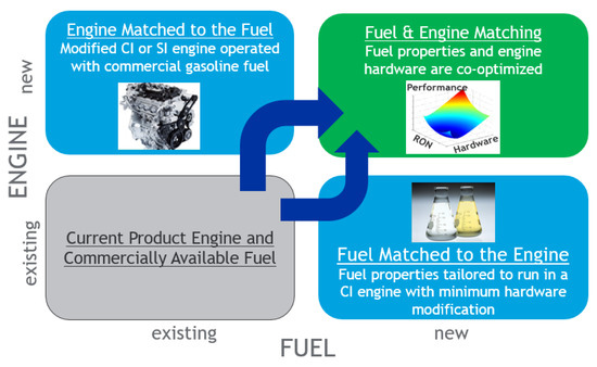
Figure 1.
GCI pathway towards fuel and engine co-optimization.
Historically, the automotive industry has considered fuel to be a constraint when designing and improving internal combustion engines (ICEs). If fuel formulation becomes a design parameter, then fuel-engine co-optimization would provide a much larger benefit in terms of CO2 emission reduction compared to the case of solely improving the ICE. This is known as fuel and engine matching. Preliminary internal results at Aramco show that by running low octane gasoline (RON80) on a custom engine mounted on a D class vehicle, it is possible to improve the fuel economy by up to 30%, enabling low temperature combustion while having vehicles that are compliant with drivability targets [18,19]. Nevertheless, the simultaneous introduction of a new fuel and a new engine into the market poses lot of challenges, and two possible routes to reach this end goal are considered. The first solution, called Engine Matched to the Fuel, commercial gasoline is combusted in a modified CI engine while in the second one, called Fuel Matched to the Engine, the ignitibility properties of gasoline are modified to be able to be used in a market-available diesel engine [20,21].
The Fuel Matched to the Engine GCI vehicle variant was showcased by Aramco in the summer of 2018 (international congress SIA powertrain in Rouen and international powertrains, fuels and lubricants meeting in Heidelberg). By running CN35 (RON45) in a recalibrated Peugeot 308, it was possible to decrease the CO2 emissions by 7% (vs. the original diesel engine) while complying with Euro 6d emissions standards.
The Engine Matched to the Fuel GCI variant is still under development at Aramco. Preliminary results have shown CO2 emissions that are similar to the ones of a diesel engine. The engine showed the possibility of reducing the BSFC by 22% and 11% versus a TGDI and diesel engine, respectively, at 1500 rpm and 6 bar of IMEP (indicated mean effective pressure).
Hybrid electric vehicle (HEV) technologies are one of the most active areas in research and development in the automotive industries. The degree of hybridization can vary from minor vehicle stop-start systems to complete vehicle redesign. A fully hybrid vehicle could reduce fuel consumption by up to 30% at an estimated price increase of up to USD 9000 per vehicle depending on vehicle size [22]. This paper suggests different HEV configurations in terms of different battery size and HEV hardware scenarios using GCI-based ICEs. GCI engines have the potential to achieve high efficiency and to significantly reduce both nitrogen oxides (NOX) and particulate matter (PM) emissions by operating under diluted and partially premixed conditions. An ongoing developmental problem with GCI engine technology is controlling the combustion process throughout the engine operating range. The combustion timing can be easily adjusted by changing the spark event and perhaps the fuel delivery for conventional gasoline SI engines, and the fuel injection timing and fuel injection amount for conventional diesel CI engines. However, it is not nearly so easy to control the GCI combustion process. Depending on the fuel’s auto-ignition quality (such as research octane number, RON, and CN) and the engine hardware configuration (such as compression ratio, CR), the GCI engine operation strategy map can be typically classified into different combustion models. This paper will address the different combustion models of GCI engines with three fuels (CN15, CN25, and CN35) compared to diesel (CN53), and hybrid vehicle simulations are then used to assess the potential of the gasoline compression ignition (GCI) engines with different hybrid architectures.
2. Materials and Methods
2.1. Experimental Setup (Fuels and Engines)
CN25 and CN35, straight run gasoline, are a generic term describing the fraction of crude oil that boils within the 30–180 °C range. It is composed of C5 to C11 hydrocarbons and has a low research octane number (RON) value. In addition, it is a refinery product that can potentially be beneficial to reduce the CO2 footprint from well-to-tank as an example of a less processed fuel. CN fuels are only processed in crude atmospheric distillation towers and undergo light hydro-desulfurization, which is in contrast to commercial diesel, which is derived from various deep conversion process units including hydrocracking, a highly energy-intensive and costly process dedicated to converting heavier streams from vacuum distillation into blending stock for the diesel and jet fuel pools. From the perspective of reducing CO2 emissions from tank-to-wheel, compared to diesel fuel, CN fuels also present intrinsic benefits. Indeed, CN25 and CN35 have a higher H/C ratio along with a higher energy content per mass unit (LHV) that directly leads to the CO2 reduction benefits of these fuels. A summary of the fuel properties is in Table 1. Depending on the straight run gasoline cut, the latter might be expected to be around 3.5%, assuming that it has the same engine efficiency. CN35 autoignition properties lie in an intermediate position within the range delimited by CN15 and diesel fuel. Compared to diesel, the tested CN fuels have lower kinematic viscosities and a reduced lubricating capability. An amount of 1000 ppm of additives (Paradyne) were added to improve the lubricity of the test fuels for the fuel injection system.

Table 1.
Summary of fuel properties.
The Table 2 represents the specification of engines and nozzle. The engine for the CN fuel tests was equipped with a variable geometry turbocharger (VGT) and a high-pressure loop (HPL) EGR system. The engine was controlled by an open ECU to control the air loop and injection set points from map or specific user dictated values. The hydraulic flow rate (HFR) of the nozzle for the CN fuels was increased to 340 cc/30 s/10 MPa. Compared to the diesel baseline, the 340 cc flow rate compensates for the lower fuel density. The engine provides a full-rated power of 88 kW at 3500 rpm and a maximum torque of 300 Nm at 1750 rpm. For all of the experiments, the emissions were logged once per second for 60 s after a stabilization period, and the average of those 60 recordings are what is presented in this paper. At the same time, the in-cylinder pressure was recorded for 250 cycles. The average of pressure data used for the calculation of IMEP and COV_imep (below 3%_Coefficient of Variation_IMEP) was also considered for all of the results in this study. Regarding the errors of the experiments, the errors are less than 0.5 mm for the fuel spray penetration measurement and up to ±2.5% for the error range of the brake thermal efficiency (BTE) for the HEV simulation (Equation (1)):
where N is engine speed (rpm), and qm fuel is mass flow of injected fuel.
Table 2.
Specification of engines and nozzle.
2.2. HEV Simulation Overviews
A simulation tool developed on MATLAB® and Simulink® was used in this study to address the positioning of the GCI technology with hybridized powertrains to meet the future CO2 demands, and it was sufficient enough to give an assessment of the potential of the proposed technology. The vehicle considered for the simulation was a typical medium-sized European C-segment passenger car with the highest demand of all of the vehicle categories in Europe. The vehicle parameters were 1500 kg for the vehicle weight without a battery, 0.3 for the cw-value, 2.28 m2 for frontal area A, and 0.230 m for the dynamic wheel radius. The weight of the battery was 14.4 kg/kWh. The engine data used for the simulation was the GT-Power engine simulation results based on the test results of other GCI studies. The aim of vehicle electric hybridization is to improve energy conversion efficiency by supporting the engine during the peak load and then to reduce emissions such as CO2. In addition, the implementation of an electric motor (EM)/generator (Gen) creates new capabilities such as full electric (EV) mode and regenerative braking. The calculated total forces are given as the input to the ICE model in the case of a conventional vehicle model. In a hybrid vehicle model, additional blocks such as EMs and a supervisor are also implemented. The supervisor will direct the power demands to ICE or Ems depending on the operating points and the strategy. The control strategy of the supervisor is the most important thing in any model, and the system behaves according to the strategy defined by the user. This is nothing but the supervisor in the hybrid powertrain, which is also known as the brain of the system. The rules of the supervisor are to:
- Continuously meet the driver’s power requests based on the accelerator and brake pedal positions and the available power in the power sources;
- To minimize the global fuel consumption;
- To maintain state of charge (SOC) of the battery between the bounds of the defined SOC;
- To make sure that the battery SOC at the end of the driving cycle reaches the user’s request.
For the control system to switch from one transition to another, certain conditions had to be defined from which transitions from different states were possible. The control system contains logic functions, and based on this, the switching takes place; this is the case for all possible cases in the control system. Once the conditions are defined, it was integrated with the other inputs for the conditions to work by integrating all of these the control system parameters. For example, the minimization of the fuel consumption target (Equation (2)):
where is the fuel path taken by engine, and s is correction factor.
It can be used to search for an optimal power split between the GCI engine and electric devices at every time step.
3. Results and Discussion
3.1. Understanding of GCI Combustion
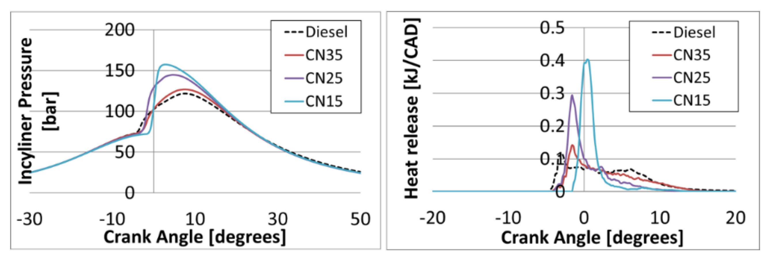
In conventional diesel engines, it is difficult to control particulates and NOX emissions. In practice, diesel fuels are significantly less volatile than gasoline fuels [23]. Auto-ignition is determined by chemical kinetics [24], which depend on the pressure and temperature development, mixture strength, and chemical composition of the fuel. Figure 2 shows the filtered in-cylinder pressure and heat release curves using different reactivity fuels (different CN fuels) on a CI engine while maintaining a similar combustion phasing with a single injection. Diesel fuel auto-ignites very quickly before the fuel and air mix sufficiently in a long diffusion and mixing-controlled combustion. If the mixing is accelerated or if the chemical reaction is slowed down such as in the case of low CN fuels, then auto-ignition can be made to occur after the fuel and air are better mixed and when the diffusion duration can be shortened. Moreover, NOX levels can be reduced by reducing the combustion temperature by either running lean, pre-mixed EGR (Exhaust Gas Recirculation). In summary, fuels that are more resistant to auto-ignition allow mixing time before combustion occurs and help to reduce NOX and smoke in CI engines. If the combustion phasing and delay are matched for any two fuels at a given condition, then their emissions behavior is also matched the auto-ignition resistance of the fuel is the most important fuel property when the injection is completed before the combustion starts [11,12,13]. However, a high peak of the maximum in-cylinder pressure and maximum pressure rise rate (MPRR) will be problematic at higher loads, and the combustion stability, hydrocarbon (HC), and carbon monoxide (CO) emissions can create a low operating load limitation because combustion is more likely to take place in lean mixture packets with better mixing caused by higher ignition delays. These problems can be significantly alleviated by managing the mixing by reducing fuel injection pressure in common rail (upstream of fuel injector) and injection strategies, e.g., multiple injections. Injector design is also likely to be important—larger hole diameter is better for gasoline fuel. The resistance of a fuel is far to auto-ignition is more important than its volatility in this type of combustion, a finding that is in line with previous observations [25,26,27].
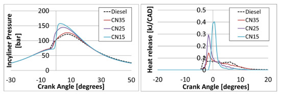
Figure 2.
Average (250 cycles) in-cylinder pressure and heat release curves using different CN fuels in a 1.6 L CI engine at 10 bar of BMEP and 2650 rpm (with single injection).
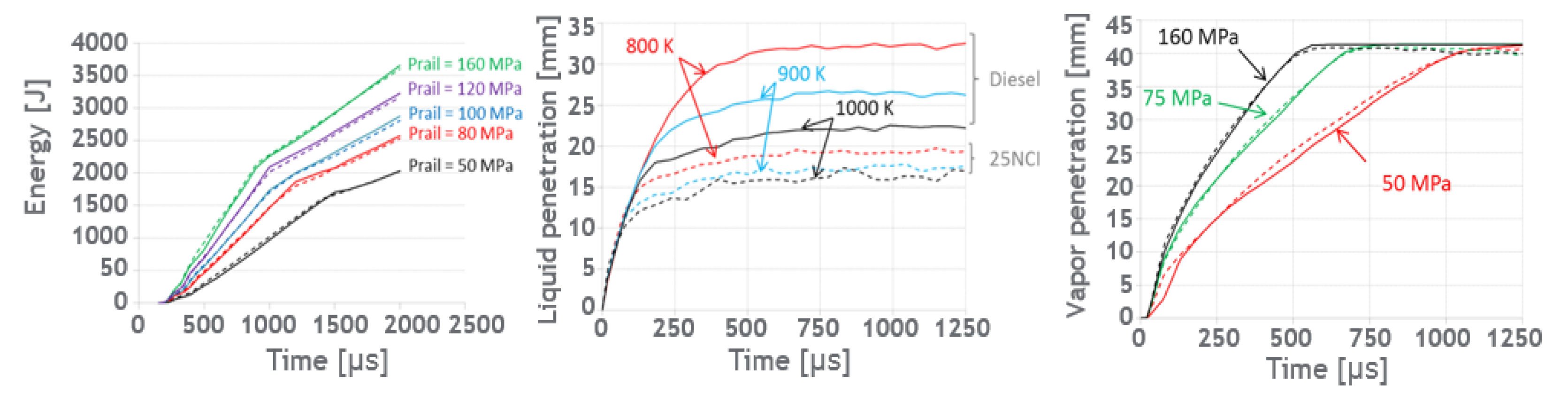
As previously mentioned, the injector design is also important to adapt low CN fuels in CI engines. The main concern of the nozzle design for CN fuels is ensuring that the same injection duration and similar energy density is delivered for low CN fuels compared to diesel. This result indicates that no additional timing will be necessary at a full load to inject the same energy quantity with low CN fuels. At this stage, this might be considered to be a positive result to mitigate the risks related to soot post oxidation, as this chemical/physical process is closely related to the injection end. Figure 3 illustrates an example of the dynamic energy flow quantity versus the energizing duration and fuel injection pressure of diesel and CN25 fuel and spray penetration in the liquid and vapor phase. The lower density of CN25 fuel (ρ_CN25 = 0.736 kg/L, ρ_diesel = 0.834 kg/L) along with its higher lower heating value LHV (LHV_CN25 = 43,287 kJ/kg, LHV_diesel = 42,660 kJ/kg) can now be considered, thereby allowing us to look at the energy that was introduced over the energizing duration. A final nozzle with 340 cc/30 s 10 MPa hydraulic flow was selected for the CN25 fuel instead of the original nozzle with a 290 flow-number for diesel fuel. Regarding spray penetration, the liquid penetration of CN25 fuel is much lower than that of diesel fuel due to its high volatility and its tendency to vaporize more quickly. Regardless of the fuel, liquid penetration is similarly reduced when increasing the air density, and CN25 liquid penetration is less sensitive to the increase of air temperature. This is fully consistent with a more volatile fuel, as less energy is required for vaporization. On the other hand, the degree of vapor penetration is similar for both fuels at the conditions tested and only a slightly longer vapor penetration was measured with the CN25 fuel.
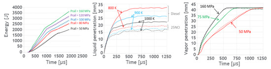
Figure 3.
(Left) Injected energy quantity versus energizing duration for different fuel injection pressures (MPa); (Center) liquid penetration for various air temperatures (air density 15 kg/m3) at fuel injection pressure 160 MPa; (Right) vapor spray penetration for different fuel injection pressures and air temperature 900 K versus time—dual (solid lines) diesel–CN25 fuel (dashed lines) is a figure. Schemes follow the same formatting.
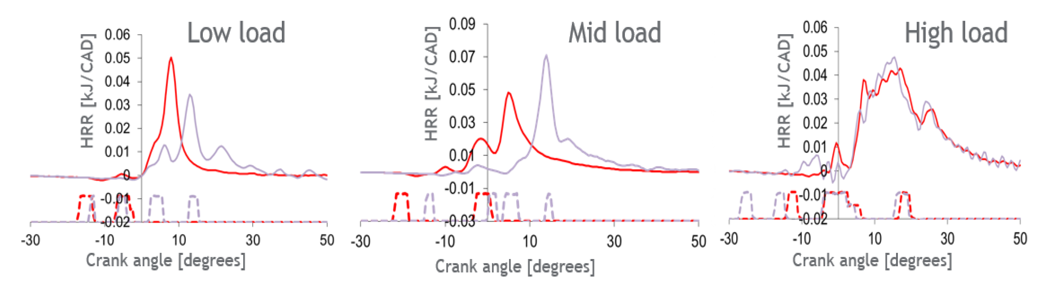
In the first stage of the GCI program, each CN fuel was tested in different single cylinder engines (SCE) to design a GCI combustion model using low CN fuels. The selection of engine hardware was an Aramco pathway towards fuel and engine co-optimization (Figure 1). For example, CN35 fuel was tested in a SCE that represented conventional CI engine hardware (1.6 L Peugeot 308 engine in Table 2). Figure 4 shows the variable combustion modes in different parts of the engine map.
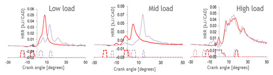
Figure 4.
Average (250 cycles) heat release rate (HRR) and injection patterns with CN35 and diesel from SCE tests (4, 7.2 and 11.4 bar of IMEP and 1500 rpm).
At a low load (1500 rpm, 4 bar of IMEP), the fuel and air are fully premixed before combustion with the high impact of low cetane number fuel. In spite of the low injection pressure with CN35, particulate emissions are very low because the CN35 combustion is fully premixed and has a long ignition delay, and the combustion duration is short. The rapid combustion process of the premixed combustion mode without post injection enables a significant reduction in the exhaust losses with CN35, resulting in a notable fuel consumption reduction. At mid load (1500 rpm and 7.2 bar of IMEP), a partially premixed combustion (PPC) mode takes place with CN35. The short duration of the combustion with CN35 and the split fueling strategy allow a reduction of the heat losses compared to diesel. Even though the diluted combustion can dramatically improve the fuel efficiency and pollutant emissions, combustion noise has to be kept at a reasonable level. At a high load (2650 rpm and 11.4 bar of IMEP) with higher temperature and pressure inside cylinder, the ignition delay is mainly dominated by the mixing properties (local A/F ratio). The impact of the CN fuel becomes negligible. The combustion mode on the CN35 fuel is similar to conventional diesel combustion; a short, premixed combustion phase and a large diffusion- and mixing-controlled combustion phase are clearly identified. In general, the NOX/particulate trade-off for GCI combustion is relatively less at all of the operating conditions compared to diesel, and more EGR is able to reach the low NOX emission target. In the last stage of the GCI program, the calibration sets, which were generated with ICE2 software, were then checked to validate the models and to assess the optimized targets based on the engine test. The final engine map was realized at the engine test cell.
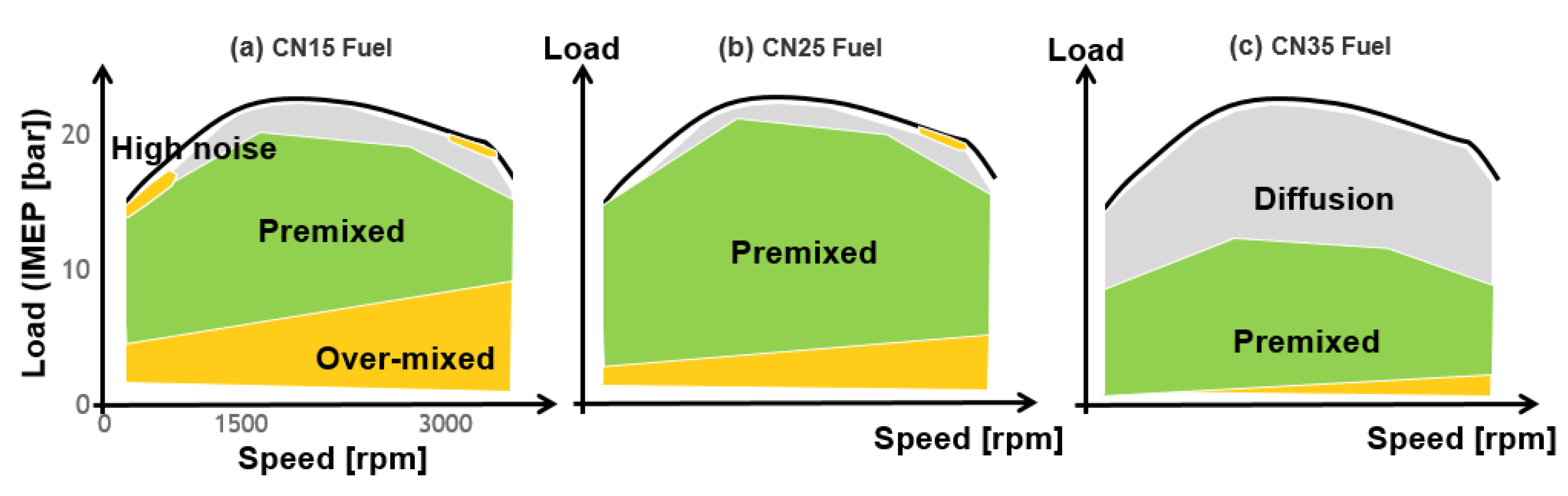
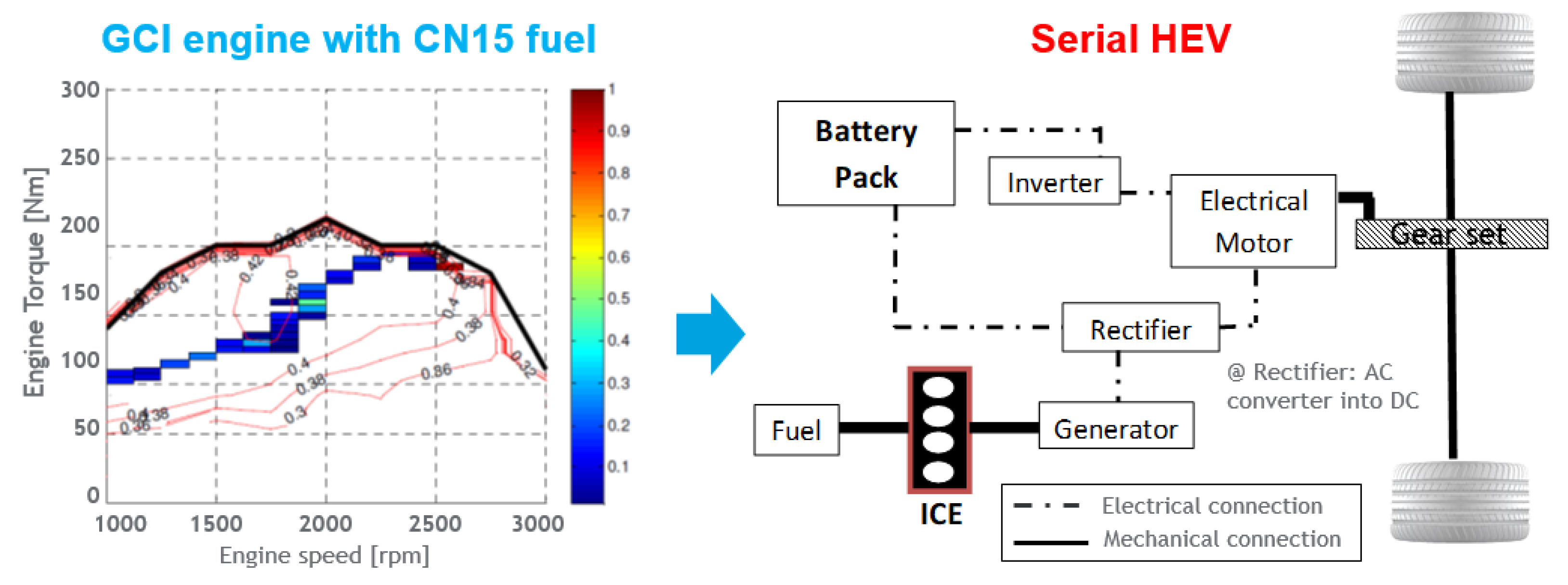
The sketches in Figure 5 are based on the Aramco projects for GCI studies on different engines (1.6–1.8 L and compression ratio of 15:1–16:1) without major hardware modifications. Based on the test results, the GCI engines with different CN fuels can be classified into several different zones and can highlight the benefits and risks in terms of the efficiency and emissions of the engine map. The figures illustrate the GCI engine map along with its benefit and challenge zones with three different CN fuels. The gray zone (diffusion combustion) is represented in a similar way to conventional diesel CI combustion. A short, premixed combustion phase and a large diffusion, mixing-controlled combustion phase are clearly identified in this zone. In that zone, GCI engine operation shows less benefits in terms of both emissions and efficiency, regardless of the fuel’s auto-ignition quality. In the green zone (premixed combustion), the high dilution of the PPC provides maximum potential with strong improvement in efficiency and pollutant emissions. The yellow zone represents diluted combustion with the risk of high combustion noise or high unburnt gas emissions due to the overmixing of fuel and air that cannot be burnt entirely. In Figure 5a, for CN 15 fuel, the low CN fuel shows great potential for significant CO2 reduction and very low particulate and NOX emissions with low temperature combustion (LTC) modes in the green zone. In this wide zone, the noise levels are relatively low due to very high EGR. The strict current regulations on emissions can be achieved in this configuration without an after-treatment system (ATS), such as a diesel particulate filter (DPF), deNOX catalyst, or selective catalytic reduction (SCR) [28,29,30]. However, some technology is necessary to improve the robustness of combustion at low load conditions and cold starting. The cold-start cranking as well as excessive HC emissions when the engine exhaust gases are not hot enough for the light-off of the ATS are still challenging. In the case of CN25 fuel, the risk of misfire or partial burning at light load is reduced. However, high levels of HC and CO emissions still have to be limited, leading to hardware modifications or the re-configuration of the oxidation catalyst system for cold conditions. By further increasing the CN of fuel (CN35 fuel), the combustion of the CN35 engine is similar to diesel mixing-controlled combustion in a wide gray zone; thus, the global efficiency on this combustion engine should be lower compared to the other types of PPCs. However, most of the risky zones could be eliminated by combining PPC mode and mixing the controlled combustion mode with minor hardware modifications for a vehicle demonstration. Based on the trend of the GCI engine map with CN fuels, different HEV configurations can be discussed to maximize the potential of the GCI engines.

Figure 5.
The GCI engine map with benefit and challenge-defined zones by fuel selections: (a) CN15, (b) CN25 and (c) CN35.
3.2. HEV Simulations with GCI Engine Test Results
3.2.1. CN35 Engine with a 48 V Mild Hybrid Configuration
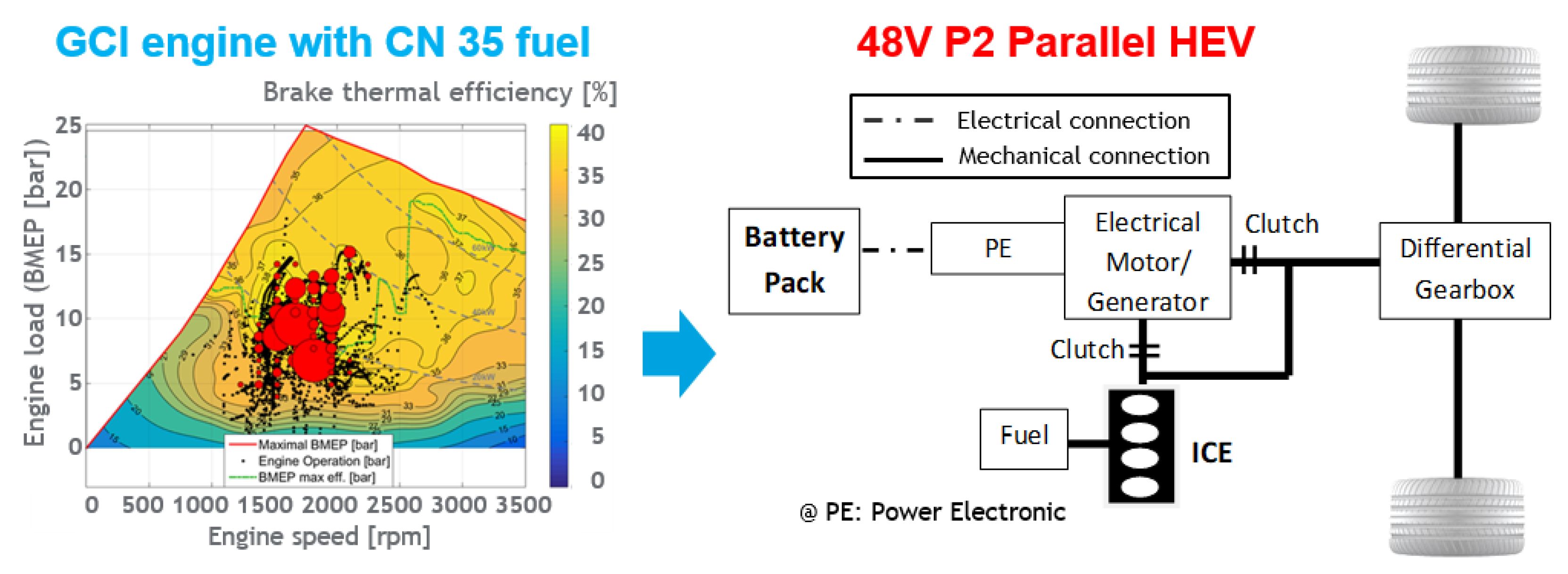
The conventional 4-cylinder, 1.6 L stock CI engine (16:1 of compression ratio) in Table 2 running on CN35 was calibrated using a DoE (design of experiments) [31] test under global operating conditions prior the final calibration on a roller test cell. Based on the combustion mode from the SCE tests, the CN35 engine was calibrated with a statistical model (ICE2 software [32]) to cover the complexity levels (high number of levels, parameters). Through the calibration of the engine, a CN35 engine map could be prepared, and the generated calibration maps could be tuned during vehicle test. The engine map, representing the sweeping engine speed and load, were then performed at the vehicle test bench to validate the engine behavior and to calculate the cumulated values of the emissions. From the vehicle test, the vehicle with CN35 addressed the vehicle test tail-pipe results, concluding that running a CI engine with CN35 fuel can fulfill the Euro 6d standard, especially when it is equipped with an ATS, i.e., a diesel oxidation catalyst (DOC), an SCR catalyst, and a DPF, providing the possibility of further CO2 benefits [20,21]. As the CN35 engine is able to operate the entire engine map, HEV simulations were performed for the CN35 vehicle with the objective of reducing CO2 emissions and pollutant emissions during the driving cycle (WLTC). Figure 6 shows the coverage of the engine response for each functioning point of cold WLTC after hybridization and recalibration. The electric components that were assessed were a 48 V of battery and a 25 kW electric motor on a P2 mild hybrid configuration. The hybridization and recalibration of the engine and ATS change the engine operating areas for the driving cycle. The mean engine efficiency for the driving cycle can be improved in HEV simulation by shifting the operating conditions, as the area of high engine efficiency is located at higher loads.

Figure 6.
The coverage of the operating points of CN35 engine on cold WLTC with 48 V P2 Parallel HEV configuration.
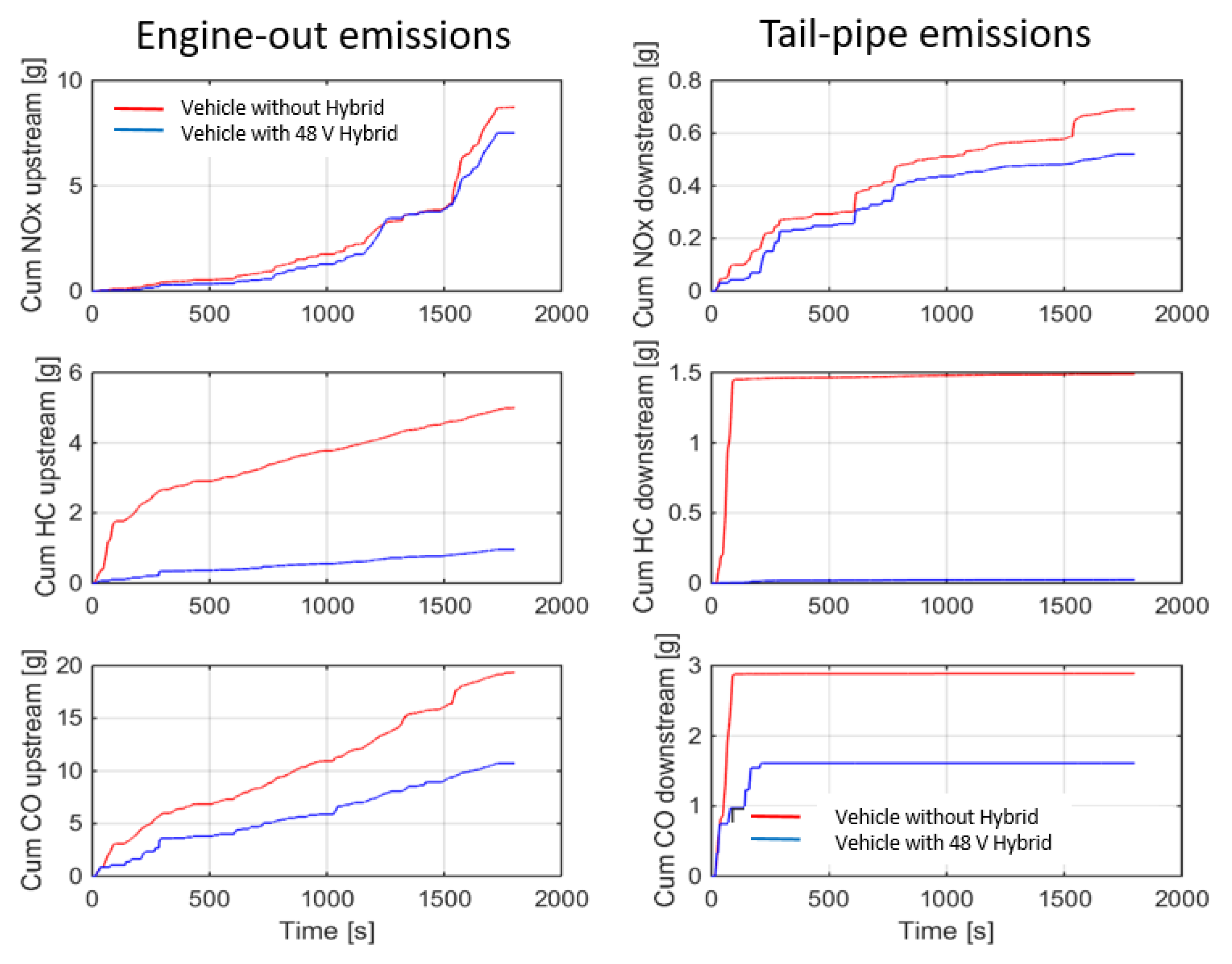
Figure 7 represents the engine-out and tailpipe emissions on cold WLTC before and after the hybridization of the CN35 vehicle. In general, HEVs allow ICEs to operate more efficiently, resulting in less pollutant emitted. The engine-out CO and HC emissions are relatively low after hybridization because the engine can be operated over less time in cold conditions, allowing for more flexible engine operation in HEV. For these reasons, the unburnt gas emissions of the CN35 vehicle with hybridization are relatively lower than the level of emissions from the conventional CN35 vehicle. A reduction in NOX emissions as well as in the trends of the emissions can be observed and are similar to those in the tailpipe. The accumulated tailpipe emissions caused by hybridization are lower than the regulations for all pollutants with significant margins. The lower tailpipe emissions are not only due to lower engine-out emissions but are also caused by the better efficiencies of ATS system on the HEV. The efficiencies of DOC and SCR were improved with better DOC lights-off and SCR urea injections by the hybridization.
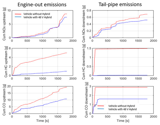
Figure 7.
Engine-out and tailpipe emissions by hybridization coverage of the operating points of CN35 engine on cold WLTC with 48 V P2 Parallel HEV configuration.
From these results of low pollutant emissions, it can be observed that further CO2 reductions are possible. From this HEV simulation, the CN35 vehicle was able to reduce 19% of CO2 emissions through hybridization, and further reductions were possible with adaptions of the ATS and ICE models of up to 5%. Total CO2 savings of up to 24.1% were achieved through the HEV simulation due to optimal engine management and ATS operating within their most favorable range of efficiency. In addition, the batteries and the electric drive allow regenerative braking which helps to recoup some of the energy lost during normal operation. From the previous engine calibration, the CN35 vehicle achieved 7% CO2 benefits compared to a reference diesel vehicle (17% of CO2 benefit compared to a modern SI engine). The potential of GCI technology was maximized, and the total CO2 savings were up to 31% and were achieved by combining the CN35 engine with a hybrid electric architecture.
3.2.2. CN25 Engine with Different Hybrid Configurations (Serial, Parallel, Serial/Parallel)
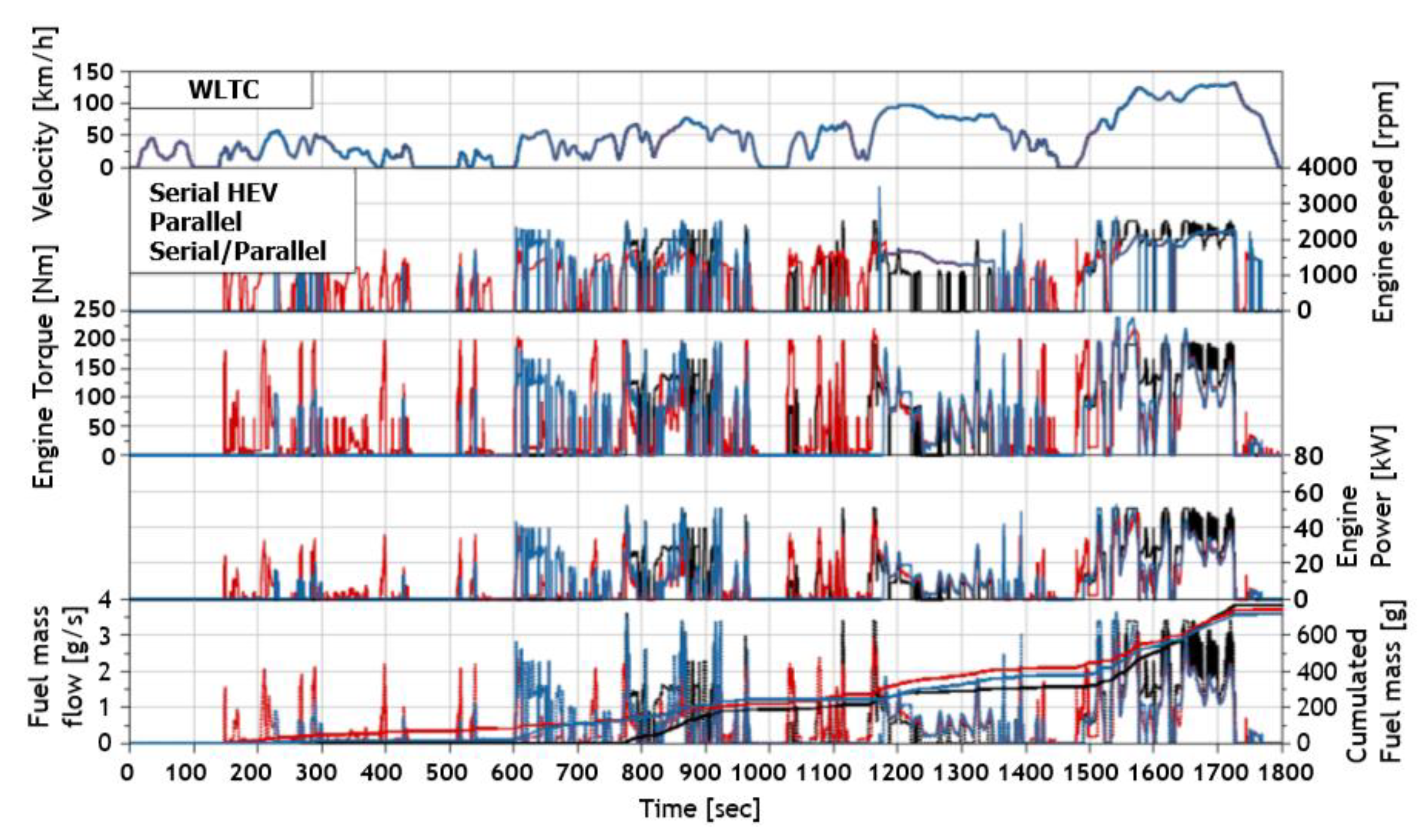
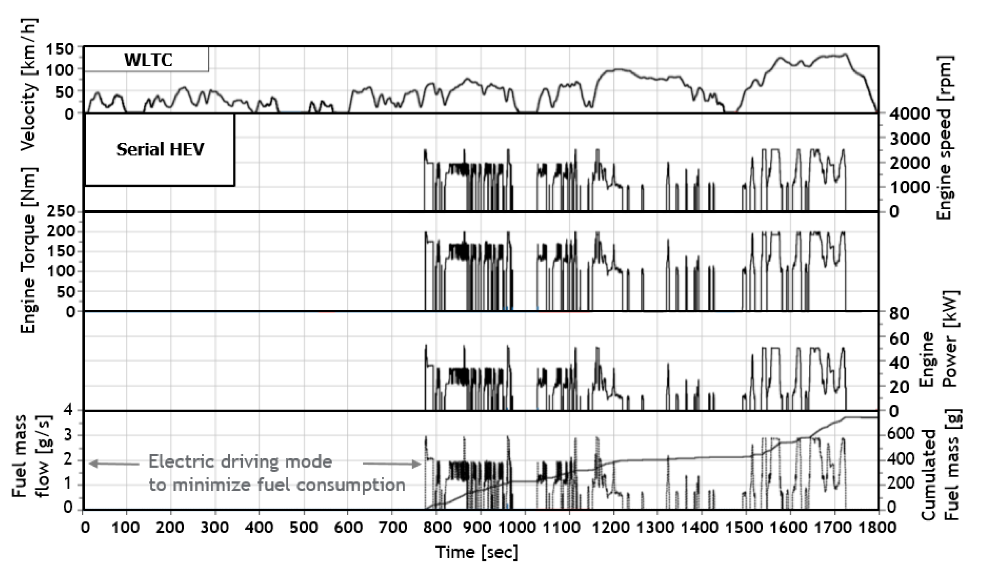
The CN25 fuel engine experiments were performed on an SCE engine test cell, and the engine data used for the simulation was the full engine map that was created by the GT-Power engine simulation results, which were based on the GCI engine test results from Aramco GCI project. The vehicle that was considered in this assessment is a typical medium-sized C-segment passenger car. The type of engine is a 1.8 L, 4-valve CI engine with a 15:1 compression ratio. Emissions were not considered in this engine approach because the engine operating in the hybridization area might produce very low engine out emissions. Figure 8 shows the results for the speed, torque, power, and fuel consumption of the CN25 engine from the HEV simulation.

Figure 8.
Speed, torque, power, and fuel consumption of CN25 engine with different hybrid configurations (WLTC).
The assessment of electric components used a 2.0 kWh battery, an 80 kW of EM, and a 50 kW generator in different full hybrid configurations. The main idea was to select a hybrid configuration through the comparison of the results for CN25 vehicles with different hybrid configurations. As shown in the figure, the power sharing duration between the engine and electric devices are longer in case of a parallel hybrid in WLTC. In hybrids with parallel drivetrains, the engine, and EM can provide mechanical power simultaneously. In the case of the serial hybrid, it only received mechanical power from the EM, which is run by either a battery or an engine-powered generator. It is for this reason that the electric driving mode is mostly utilized at low vehicle speeds to minimize fuel consumption, and the status of the ICE is determined by the state of charge (SOC) values of the battery. In case of a non-plug-in hybrid (non-PHEV), the serial/parallel configuration has some fuel consumption potential compared to other hybrid configurations. In spite of the system complexity of the serial/parallel hybrid, this hybrid has more flexibility for the energy management for the SOC and fuel consumption. Understanding the advantages of the gearbox (more variants with different gearbox location and different number of gears) and guiding the proposition of better topology for the complex system are the main reasons for the improvements to the serial/parallel hybrid.
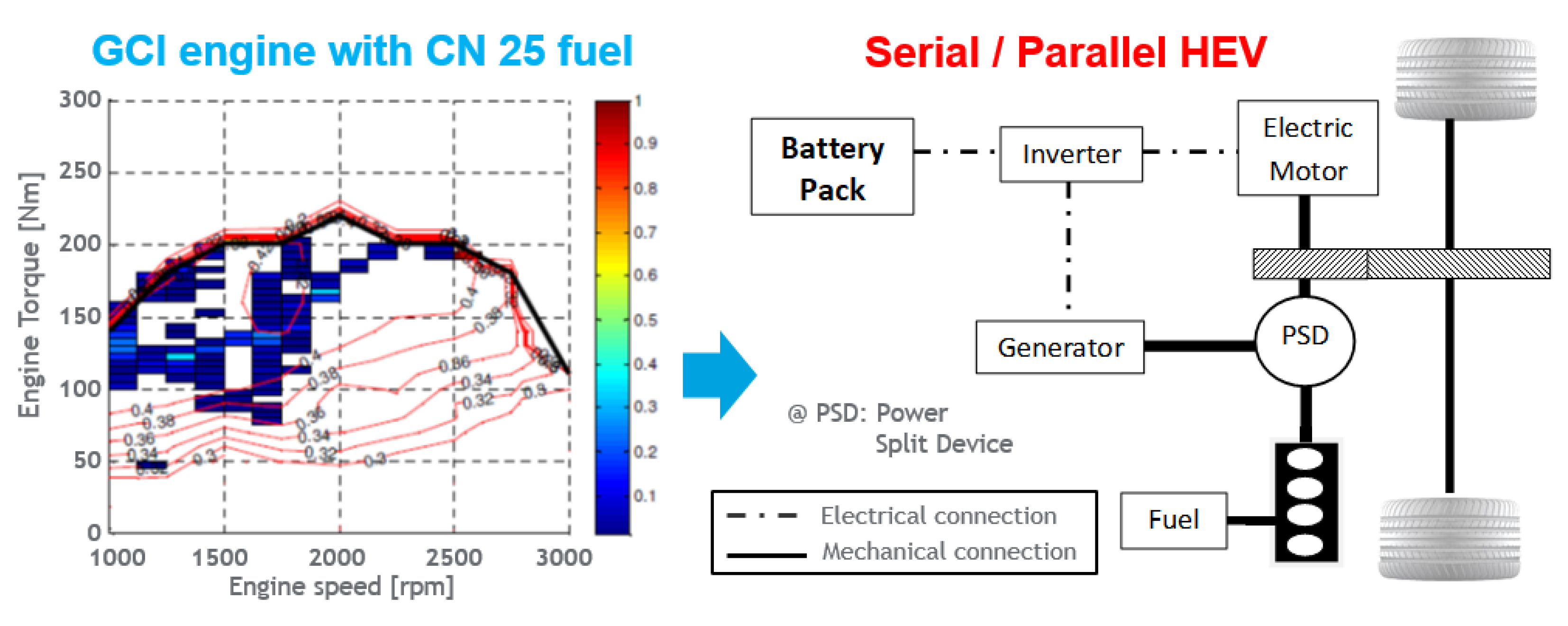
Figure 9 shows the coverage of the engine operating points of WLTC after the hybridization (serial/parallel configuration). In general, such an engine possesses a peak effective efficiency of approximately 38%. It is obvious that the WLTC operating point distribution is in the optimum efficiency range for this engine. Therefore, the mean engine efficiency during the cycle reaches a value of 31.9%. This result is based on warm measured engine maps. The CN25 engine possesses a high peak efficiency of approximately 42% over a wide area of the engine map. However, the high engine efficiency area is located at high engine loads. The benefit of CO2 from the high engine efficiency will not be as high, as the engine operates at low engine efficiencies during WLTC when it is not hybridized. A CN25 engine cannot benefit from its high peak efficiency to a full extent. The operation points are shifted to higher loads and hence higher engine efficiencies when hybridized. As a result, the mean engine efficiency during WLTC increases to 38%. Consequently, the CN25 engine is the most suitable for hybridization. The CN25 engine achieves a fuel consumption improvement of about 9% compared to the Euro 6d-based engine. An additional benefit of 28.1% can be realized when the vehicle offers the discussed hybridization and when the charge sustain mode is considered. In total, a reduction of 37% can be seen based on weighted CO2 emissions according to the WLTC certification.

Figure 9.
Energy-weighted operating point distribution of CN25 engine on WLTC and serial/Parallel hybrid configuration.
3.2.3. CN15 Engine with a Plug-In Serial Hybrid Configuration
The CN15 fuel engine experiments were performed on an SCE engine test cell, and the engine data used for the simulation was the full engine map created by GT-Power engine simulation results. Due to high resistance to the autoignition of the fuel, the CN15 engine is only able to run in the limited operating zone (medium and high loads as mentioned in Figure 5) without any ignition improvers, e.g., spark assist system and dual fuel system. Considering the operating range, a serial hybrid configuration was selected for the engine in this study. is the chosen engine was a 1.8 L, 4-valve CI engine with a 15:1 compression ratio. Emissions were also not considered in this engine approach because the engine operating area affected by hybridization might produce very low engine out emissions.
Figure 10 shows the results for the speed, torque, power, and fuel consumption of the CN15 engine on the serial hybrid. The assessment of the electric components are an 8.8 kWh of battery (concern of PHEV with 50 km of e-driving range) and 100 kW of EM and 50 kW of generator. In case of non-PHEV, the electric driving mode is mostly utilized at low vehicle speeds to minimize the fuel consumption, and the ICE status was determined by the SOC values. In this approach, a PHEV makes sense for vehicles with a large battery package and electric device size. From the PHEV simulation, the CO2 benefits are up to 75% for the configuration.
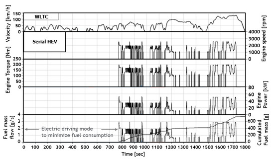
Figure 10.
Speed, torque, power, and fuel consumption of CN15 engine with serial hybrid configuration (WLTC).
Figure 11 shows the energy-weighted engine operating points of the CN15 engine on WLTC after the hybridization (serial hybrid configuration). Consequently, the CN15 engine is the most suitable for serial hybridization. In the serial configuration, the entire mechanical transmission between the engine and wheel was replaced by the electric transmission that consisted of EM as the electrical generator. With a generator, the EM and ICE operate independently of each other, with each operating at its most efficient range. The limited operating range of the CN15 engine with low reactivity fuel is matched into the hybrid configuration without any ignition improver. Thanks to hybridization, the engine is able to operate at the optimum efficiency range in WLTC. Therefore, the mean engine efficiency during the cycle reached a value of 39%. This result is based upon the warmth-measured engine maps. However, the disadvantage of this configuration is the large battery package and the large EM required for the vehicle (high cost of vehicle) because it has to provide the maximum possible power to the wheels.
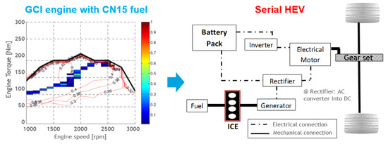
Figure 11.
Energy-weighted operating point distribution of CN15 engine on WLTC and serial hybrid configuration.
3.3. CO2 Benefits of GCI Ehicles and Life Cycle Assessments
A life cycle assessment (LCA) is a methodology to assess the environmental impacts of a product or service throughout its life. The final CO2 benefits, expected emission targets, and cost requirements of the GCI hybrid simulations are summarized for each vehicle in Table 3. The CN35 vehicle variant was showcased by Aramco in a recalibrated Peugeot 308, where it was possible to decrease the CO2 emissions by 7% (vs. the original diesel engine) while complying with Euro 6d emission standards. From the HEV simulation, a potential of 24.1% in CO2 reduction was demonstrated through the optimization of the ICE and adapted ATS models. The expected new EU pollutant emission standards will be able to be fulfilled using a 48 V 1 kWh battery and P2 architecture and will be cheaper compared to conventional ICE vehicles. During the full HEV simulations with different hybrid architectures for CN25 engines, the serial/parallel configuration showed some fuel consumption potential with more energy management flexibility compared to other hybrid configurations. In this case, the total CO2 benefits reached 37%. The complexity of the HEV and the additional hybridization costs are the disadvantages of this approach. The CN15 engine was matched to a serial hybrid configuration, and a total of 75% CO2 benefits were able to be reached in the case of the plug-in hybrid. PHEVs are also promoted worldwide as a solution to improve local climate issues in the transport sector. However, BEVs and PHEVs require a larger battery package and have higher costs.
Table 3.
Summary of HEV simulation results and cost estimation of the proposed GCI hybrid vehicles (− low cost, ○ similar cost like reference, + high cost).
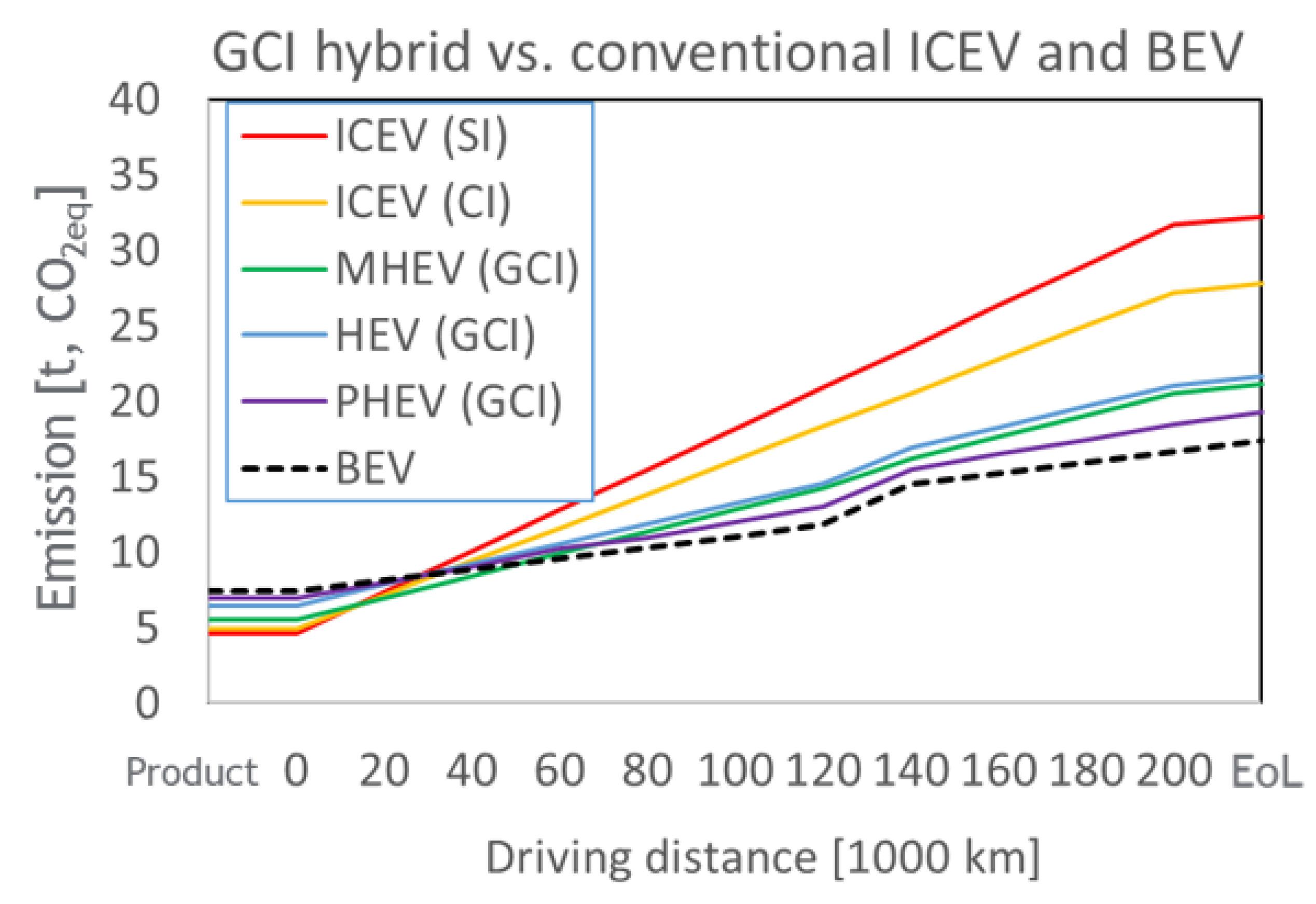
Figure 12 shows a life cycle analysis of different GCI hybrids compared to conventional ICE vehicles (ICEVs), gasoline engines (SI) and diesel engines (CI), and pure battery electric vehicles (BEV) with a 24 kWh battery package. The accumulated GHG were calculated based on a life cycle analysis [33]. The lifetime o vehicle mileage average is assumed to be 200,000 km for all vehicle types, and the battery lifetime is 130,000 km, part of the constituent materials of which can be recycled for all of the tested electrified vehicles. For PHEV, the annual mileage on e-driving mode can be determined by the electric driving modes and based on the literature is around 80% on WLTC. The accumulated tank to wheel (TTW) GHG emissions can be calculated using the HEV simulation, and the results are similar to those obtained in the previous chapter for conventional ICEVs and BEV. The average carbon intensity of the electricity used for PHEV and BEV uses the EU mix 2020 base case (241 gCO2eq/kWh), and thermal energy sources are used throughout all of the energy production and logistics processes. The reference vehicle assumed for all of the vehicles in the study is based on a C-Segment medium car, such as the VW Golf, Ford Focus, or Opel Astra. The manufacturing of vehicles and batteries and the end of life (EoL) are considered in this study using Gabi software [33].
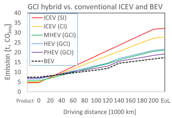
Figure 12.
Accumulated GHG emissions during the vehicle lifetime for GCI hybrids versus conventional ICEV and BEF based on life cycle analysis (LCA), (EoL: end of life, WLTC).
As shown in the figure, despite having a significant carbon burden from the beginning of its manufacturing stage, BEV appears to have the lowest accumulated lifetime GHG emission levels when set at 17.3 t CO2eq. On the other hand, ICE passenger vehicles display the highest levels of GHG emissions in the base case as a result of the combination between the fossil source and lower thermodynamic efficiency. Based on the LCA results, the conventional ICEVs produce more than 14–10 t CO2eq in their lifetime compared to BEV. In case of GCI hybrids, the GHG emission gaps can be reduced to 2–4 t CO2eq. In the world, electrical power is generated by power plants that use different primary energy sources. These primary energy sources are all of natural origin; they include fossil fuels (coal, petroleum, natural gas) and low-carbon energy sources (nuclear, renewables) that release a lot or a little CO2 to the atmosphere. The GHG emissions of BEV and PHEV depend on the rate of de-carbonization and its effects on the carbon intensity of the electricity that is generated, and a differentiated technology deployment pathway can be developed. In some cases, where the grid is sufficiently de-carbonized and where charging infrastructures are widely available, a direct transition to BEV could be a feasible option; however, in other cases, an advanced GCI hybrid technology can be the transitionary technology to bridge the gap in the interim period.
4. Conclusions
In this paper, GCI engines with three different fuels (CN15, CN25, and CN35) were compared to diesel (CN53), and hybrid vehicle simulations were used to assess the potential of the GCI engines with different hybrid architectures:
- This study presents different HEV configurations with GCI engines. Depending on different battery size and HEV hardware scenarios, the engines operate in a high efficiency region;
- From HEV simulation, in case of non-PHEV, the GCI hybrid vehicles are able to reduce CO2 emissions (TTW) by up to 37% compared to the reference CI vehicle (up to 45% compared to modern SI engine). The CO2 benefit is up to 75% in the case of the PHEV scenario, but it requires a larger battery package and has a higher vehicle cost;
- From a life cycle assessment (LCA), vehicles running on GCI fuels and hybrid technologies, such as BEV, show potential (around 10 ton of GHG emission reduction in lifetime compared to a conventional SI engine vehicle) to provide similar effects on accumulated GHG emissions.
Given the sustainability constraints of the critical raw mineral supply and the heterogeneity of regional power grids, advanced GCI hybrid architectures, with varying degrees of electrification, can bridge this gap in the interim.
Funding
This research received no external funding.
Institutional Review Board Statement
Not applicable.
Informed Consent Statement
Not applicable.
Conflicts of Interest
The author declares no conflict of interest.
References
- Sims, R.; Schaeffer, R. Chapter 8: Transport IPCC WGIII Fifth Assessment Report, Report. Available online: mitigation2014.org/report/ipcc_wg3_ar5_chapter8.pdf (accessed on 19 October 2015).
- The Outlook for Energy: A View to 2040, ExxonMobil 2016. Available online: http://cdn.exxonmobil.com/~/media/global/files/outlook-for-energy/2016/2016-outlook-for-energy.pdf (accessed on 7 February 2016).
- World Energy Council. Global Transport Scenarios 2050. WEC London. 2011. Available online: http://www.worldenergy.org/wp-content/uploads/2012/09/wec_transport_scenarios_2050.pdf (accessed on 22 October 2015).
- U.S. Energy Information Administration. International Energy Outlook 2013. DOE/EIA−0484. 2013. Available online: http://www.eia.gov/forecasts/ieo/pdf/0484(2013).pdf (accessed on 22 October 2015).
- BP. Statistical Review of World Energy 2015 Workbook. Available online: http://www.bp.com/en/global/corporate/about-bp/energy-economics/statistical-review-of-world-energy.html (accessed on 26 August 2015).
- European Commission. The European Green Deal, COM (2019) 640 Final; The European commission: Brussels, Belgium, 2019. [Google Scholar]
- 2015 United Nations Climate Change Conference in Paris. In The Paris Agreement is a Legally Binding International Treaty on Climate Change; The United Nations: Paris, France, 2015.
- ICCT Report—The European Commission Regulatory Proposal for Post-2020 CO2 Targets for Cars and Vans: A Summary and Evaluation. Available online: https://theicct.org/publications/ec-proposal-post-2020-co2-targets-briefing-20180109 (accessed on 30 January 2018).
- Carlier, M. Number of vehicles in use worldwide 2006–2015; The Statistics Portal. Available online: http://www.statista.com/statistics/281134/number-of-vehicles-in-use-worldwide/ (accessed on 8 July 2016).
- Abnett, K. EU to target 30 million electric car by 2030. Available online: https://www.reuters.com/article/us-climate-change-eu-transport-idUSKBN28E2KM (accessed on 4 December 2020).
- Kalghatgi, G.T.; Hildingsson, L.; Johansson, B.; Harrison, A.J. Low NOx, low smoke operation of a diesel engine using premixed enough compression ignition—Effects of fuel autoignition quality, volatility and aromatic content. In Proceedings of the THIESEL 2010, Thermo and Fluid Dynamic Processes in Diesel Engines, Valencia, Spain, 14−17 September 2010; pp. 409–420. [Google Scholar]
- Won, H.W.; Peters, N.; Tait, N.; Kalghatgi, G.T. Sufficiently premixed compression ignition of a gasoline-like fuel using three different nozzles in a diesel engine. Proc. Inst. Mech. Eng. Part D J. Automob. Eng. 2012, 226, 698–708. [Google Scholar] [CrossRef] [Green Version]
- Won, H.W.; Pitsch, H.; Tait, N.; Kalghatgi, G.T. Some effects of gasoline and diesel mixtures on partially premixed combustion and comparison with practical fuels, gasoline and diesel, in a diesel engine. Proc. Inst. Mech. Eng. Part D J. Automob. Eng. 2012, 226, 1259–1270. [Google Scholar] [CrossRef] [Green Version]
- Akihama, K.; Kosaka, H.; Hotta, Y.; Nishikawa, K. An Investigation of High Load (Compression Ignition) Operation of the Naphtha Engine—A Combustion Strategy for Low Well-to-Wheel CO2 Emissions. SAE Int. J. Fuels Lubr. 2009, 1, 920–932. [Google Scholar] [CrossRef]
- Rose, K.; Cracknell, R.; Rickeard, D.; Ariztegui, J. Impact of Fuel Properties on Advanced Combustion Performance in a diesel Bench Engine and Demonstrator Vehicle. SAE Tech. Pap. 2010. [Google Scholar] [CrossRef] [Green Version]
- Liang, X.; Zheng, Z.; Zhang, H.; Wang, Y.; Yu, H. A review of early injection strategy in premixed combustion engines. App. Sci. 2019, 9, 3737. [Google Scholar] [CrossRef] [Green Version]
- Du, J.; Chen, X.; Liu, L.; Liu, D.; Ma, X. Mechanism of combustion noise influenced by pilot injection in PPCI diesel engiens. Appl. Sci. 2019, 9, 1875. [Google Scholar] [CrossRef] [Green Version]
- Cho, K.; Latimer, E.; Lorey, M.; Cleary, D.; Sellnau, M. Gasoline Fuels Assessment for Delphi’s Second Generation Gasoline Direct-Injection Compression Ignition (GDCI) Multi-Cylinder Engine. SAE Int. J. Engines 2017, 10, 1430–1442. [Google Scholar] [CrossRef]
- Cho, K.; Zhang, Y.; Cleary, D. Investigation of Fuel Effects on Combustion Characteristics of Partially Premixed Compression Ignition (PPCI) Combustion Mode at Part-Load Operations. SAE Int. J. Engines 2018, 11, 1371–1384. [Google Scholar]
- Won, H.; Bouet, A.; Kermani, J.; Duffour, F. Low RON gasoline calibration on a multi-cylinder compression ignition engine to fulfill the Euro 6d regulation. In Proceedings of the 13th International Conference on Engine & Vehicle, Port Jefferson, NY, USA, 21–25 June 2015; Paper Number 2017-24-0091. 2017. [Google Scholar]
- Won, H.; Bouet, A.; Kermani, J.; Duffour, F.; Dosda, S. Combustion optimization of a multi-cylinder CI engine running with a low RON gasoline fuel considering different air loop and after-treatment configurations. SAE Tech. Pap. 2017. [Google Scholar] [CrossRef]
- Wolfram, P.; Lutsey, N. Electric Vehicles: Literature Review of Technology Costs and Carbon Emissions, International Council on Clean Transportation (ICCT), Working Paper 2019-14. 2016. Available online: www.theicct.org (accessed on 8 September 2021).
- Kalghatgi, G.T. Auto-ignition quality of practical fuels and implications for fuel requirements of future SI and HCCI engines. SAE Tech. Pap. 2005. [Google Scholar] [CrossRef]
- Westbrook, C.K. Chemical kienetics of hydrocarbon ignition in practical combustion systems. Proc. Combust. Inst. 2000, 28, 1563–1577. [Google Scholar] [CrossRef] [Green Version]
- Li, T.; Okabe, Y.; Izumi, H.; Ogawa, H. Dependence of ultra-high EGR low temperature combustion on fuel properties. SAE Tech. Pap. 2006. [Google Scholar] [CrossRef]
- Risberg, P.; Kalghatgi, G.; Ångström, H. Auto-ignition quality of diesel-like fuels in HCCI engines. SAE Trans. 2005, 114, 883–893. [Google Scholar] [CrossRef]
- Schleyer, G.; Duffy, K.; Liechty, M.; Hardy, W.; Bessonette, P. Effects of fuel property changes on heavy duty HCCI combustion. SAE Trans. 2007, 116, 242–254. [Google Scholar]
- Sellnau, M.; Sinnamon, J.; Hoyer, K.; Husted, H. Gasoline Direct Injection Compression Ignition (GDCI)—Diesel-like Efficiency with Low CO2 Emissions. SAE Int. J. Engines 2011, 4, 2010–2022. [Google Scholar] [CrossRef]
- Sellnau, M.; Sinnamon, J.; Hoyer, K.; Kim, J. Part-Load Operation of Gasoline Direct-Injection Compression Ignition (GDCI) Engine. SAE Tech. Pap. 2013. [Google Scholar] [CrossRef]
- Sellnau, M.; Moore, W.; Sinnamon, J.; Hoyer, K. GDCI Multi-Cylinder Engine for High Fuel Efficiency and Low Emissions. SAE Int. J. Engines 2015, 8, 775–790. [Google Scholar] [CrossRef]
- Röpke, K.; Gaitzsch, R.; Haukap, C.; Knaak, M.; Knobel, C.; Neßler, A.; Schaum, A.; Schoop, U.; Tahl, S. DoE—Design of Experiments, Methods and applicationsin engine development. SV Corp. Media 2005, 889503. Available online: https://onlinelibrary.wiley.com/doi/10.1002/qre.941 (accessed on 8 September 2021).
- Nadal, A.; Castagné, M.; Kermani, J.; Nicolas, F.; Degeilh, P.; Brichard, T.; Poquet, V. Application of global model based calibration methodology to optimize a 2.3 litre diesel engine with SCR on WLTC cycle. proceedings of the Conference Design of Experiments (DoE) in Powertrain Development, Berlin, Germany, 11–12 June 2015. [Google Scholar]
- Yugo, M.; Gordillo, V.; Shafiei, E.; Megaritis, A. A look into the life cycle assessment of passenger cars running on advanced fuels. In Proceedings of the SIA Powertrain and Power Electronics Conference, Online, 9–10 June 2021. [Google Scholar]

Publisher’s Note: MDPI stays neutral with regard to jurisdictional claims in published maps and institutional affiliations. |
© 2021 by the author. Licensee MDPI, Basel, Switzerland. This article is an open access article distributed under the terms and conditions of the Creative Commons Attribution (CC BY) license (https://creativecommons.org/licenses/by/4.0/).