Abstract
Geothermal energy resources associated with disused hydrocarbon wells in Italian oilfields represent a considerable source of renewable energy. Using the information available on Italian hydrocarbon wells and on-field temperatures, two simplified closed-loop-type systems models were implemented in the Python environment and applied to a selected hydrocarbon well (Trecate4) located inside the Italian Villafortuna–Trecate field (Northwestern Italy). Considering the maximum extracted working fluid temperatures, Coaxial WBHE turned out to be a better performing technology than the U-tube version. The obtained outflow temperatures of the working fluid at the wellhead for Coaxial and U-tube WBHEs of 98.6 °C and 84 °C, respectively, are both potentially exploitable for ensuring a multi-variant and comprehensive use of the resource through its application in sectors such as the food industry, horticultural and flower fields.
1. Introduction
Energy production using affordable, sustainable and reliable resources has become one of the central topics of European development policy vision while concerns over climate change and energy independence have given increasing importance to the implementation of non-fossil fuels in the national energy mix. Advances in technological capabilities and substantial cost reductions in renewables are needed to facilitate the integration of these energy sources in end-use applications for the scaled transformation of existing energy systems.
Of the available environmentally friendly energy resources, geothermal energy can be used directly for heating and cooling buildings as well as to produce electricity. Moreover, depending on the specific geological, hydrogeological and thermo-physical conditions such as temperature, flow rate and geothermal water mineralisation grades, prevailing in an area to be analysed, there are several possibilities for the industrial and economic utilisation of heat energy potentially accumulated.
Direct use technologies are currently growing in applications including district heating, space heating with the use of heat pumps, agricultural purposes (e.g., greenhouses), fish farming, milk pasteurization and other purposes. By cascading exploitations of available heat, realising a multi-variant and comprehensive use of the resource is possible according to the corresponding temperature demand [1].
In [2], the authors presented a review of worldwide applications of geothermal energy for direct utilization, updating the previous survey carried out in 2015 and comparing data from the previous versions. The total installed capacity, reported at the end of 2019, for geothermal direct utilization worldwide turns out to be equal to 107,727 MWt, with a percentage increase of 52% over 2015. The total annual energy use is 1,020,887 TJ (283,580 GWh), indicating a 72.3% increase and a compound annual growth rate of about 11.5%.
According to the information available in [2], in Italy there are 37 direct-use geothermal sites, 5 of which are for district heating, 5 for individual space heating, 1 was an industrial process site, 6 for fish farming, 4 for greenhouse heating and 16 for swimming and bathing. At the end of 2017, the total installed capacity exceeds 1400 MWth, with a corresponding heat utilization of 10,915 TJ/yr. The main share of geothermal direct use is held by the space heating sector (42% of the total energy, 52% of the overall installed capacity), followed by thermal balneology (32% for both values) and fish farming (18% and 9% respectively). Agricultural applications, industrial processes and other minor uses together account for around 8% of total geothermal use.
Despite the great potential for development in Italy, the available geothermal energy resources for direct use are not fully developed, and the national current urban and regional energy paradigms rely heavily on fossil fuels. The share of geothermal heat production in Italy, excluding geothermal heat pumps, in the total thermal production from Renewable Energy Sources (RES) is limited to a percentage of 1.3% [3].
Over time, a variety of hydrocarbon reservoirs has been identified, and Italian sedimentary basins have been explored for both oil and gas extraction purposes. Since 1985, 7246 wells have been drilled for hydrocarbon extraction in Italy, 898 of which are located onshore with varying operational statuses [4]. Additionally, geological and geophysical exploration campaigns into the deepest regions of such geological contexts have ascertained the coexistence of hydrocarbons and low-temperature to medium-temperature geothermal energy resources [5,6]. Recent investigations have attempted to assess geothermal potentials, exploring deep geothermal resources in different regions and reconstructing heat flow maps at different depths [7,8,9].
Since they are stored in subsurface geological formations and associated with hydrocarbons, geothermal resources need to be extracted before use. Decommissioned or disused oil and gas wells, especially those in mature oilfields, represent good candidates for geothermal heat exploitation, providing access to deep subsurface energy resources. Existing wellbores, surface facilities and infrastructures and available geological and geophysical data can enhance potential geothermal projects in oilfields by reducing capital costs and minimising risk and inconvenience [10,11].
Over time, energy companies and researchers have begun to put greater effort into developing various strategies for harnessing this type of deep geothermal energy resource. The majority of studies that have been carried out on existing abandoned petroleum wells have focused on open-loop systems designed to repurpose petroleum fields as geothermal reservoirs [12,13].
Although geothermal open-loop systems in sedimentary formations may provide a sustainable solution where the geothermal potential and heat demand coincide [14,15], these technologies are subject to some technical problems, including groundwater recession, corrosion and scaling. Further important issues are represented by the reinjection of fluids [16,17] and by the complex additional exploration activities [18].
An effective and optimally dimensionalized alternative for relatively low energy demand is represented by the use of closed-loop deep geothermal systems. Unlike conventional open-loop geothermal systems, heat carrier fluids in closed-loop systems circulate inside of a wellbore heat exchanger (WBHE), while no ground fluids are extracted from the surrounding rocks. Moreover, corrosion and scaling problems are limited. Due to their proven advantages, a large number of studies that deal with developing closed-loop system technologies have been carried out [19,20].
Despite the recent success of some theoretical oilfield geothermal closed-loop system experiments, several challenges remain related to harnessing geothermal resources at a larger scale in oilfields using closed-loop type technologies, including low levels of thermal energy recovery and low energy conversion efficiency [21]. Moreover, researchers have indeed primarily focused their attention on analysing the impacts on the energy performance of changes in working fluid-related parameters, such as initial temperature and injection flow rate values.
In the elaborations reported in [22,23,24], the authors fixed the values of different thermophysical parameters (thermal conductivity, volumetric heat capacity and rock density) as weighted mean values. However, due to the continuous spatial and vertical variability of geological formations associated with deep wells in oilfields, the thermophysical parameters of geological strata, as well as the depth of the strata and their thickness, need to be properly considered in order to achieve increasingly accurate and realistic estimates of heat exchanger performance.
Given the above considerations, the proposed study aims primarily at contributing to the discussion by encouraging reflection on the potential benefits of using low-temperature to medium-temperature geothermal energy resources associated with dismissed Italian hydrocarbon wells. Using the information about Italian hydrocarbon wells and on-field temperatures available from both the National Mining Office of the Italian Ministry for Economic Development (MISE) and the Italian National Geothermal Database, the attention is focused on two different geothermal closed-loop-type technologies: U-tube and coaxial wellbore heat exchangers (WBHEs). Two different simplified heat exchange models (Coaxial and U-tube WBHE) and thermal resistance systems, described in references [24,25], respectively, were implemented in the Python environment and applied to a selected hydrocarbon well (Trecate4) located inside the Italian Villafortuna–Trecate field (Northwestern Italy).
The main purposes of the study were to analyse heat exchange mechanisms by examining the main factors that affect extraction efficiency from a geological perspective, proposing a simplified and automated tool for the identification of the best closed-loop configuration that allows maximal heat recovery from a selected hydrocarbon well.
The assumption that the thermophysical parameters (thermal conductivity, volumetric heat capacity and rock density) are constant values has been overcome by considering and implementing detailed stratigraphic data in the proposed models. The final use of the potentially accumulated heat energy was considered as possible in direct applications through a cascade plant system, which provides specific thermal energy amounts to different production cycles in manufacturing, agricultural and recreational districts near the oilfield.
2. Materials and Methods
2.1. Test Site: The Villafortuna–Trecate Oilfield
A variety of petroleum systems has been identified in Italy as a result of complex geological and sedimentary history. According to [26], Italian hydrocarbon occurrences can be classified as associated with three main tectono-stratigraphic systems: the carbonate Mesozoic substratum of the foredeep/foreland area and the external thrust belts, thrusted terrigenous Oligo-Miocene foredeep wedges (Southern Alps, Northern Apennines, Calabria and Sicily) and terrigenous Pliocene-Pleistocene successions of the late foredeep basins of the Apennines, in both the Central and Northern Adriatic Sea and the Po Plain.
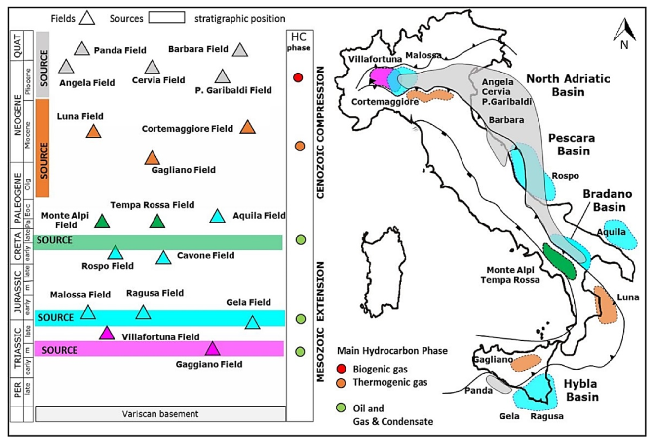
In this study, attention is focused on an analysis of the geothermal resources potentially associated with a disused hydrocarbon well named Trecate4, which is located within the Villafortuna–Trecate oilfield (Figure 1).

Figure 1.
Simplified stratigraphic and geographic location of the Italian petroleum systems (Modified from [30]. Copyright Geological Society of London, 2018).
The Villafortuna–Trecate system represents one of the largest oil accumulations of the Italian Middle Triassic carbonate petroleum system. It involves dolomitized platform units of Late Triassic–Early Jurassic that were charged by Middle Triassic carbonate source rocks deposited in the confined basins created by rifting. Due to its depth, it can be pursued only in the outer sector of the foredeep and in the foreland regions (the Piedmont area) [27]. The main reservoir associated with the Villafortuna–Trecate field was identified at a depth between 5800 m and 6100 m [28].
The selection of the proposed case study was guided by the preliminary results presented in [29], which identified the wells located within the Villafortuna–Trecate oilfield as the most suitable to be converted into geothermal ones and also in function of their deep and constructional features. Considering the related thermophysical parameters, the amount of thermal energy that they would allow recovering turned out to be larger in comparison with the wells located in comparable Italian sedimentary contexts.
Detailed litho-stratigraphic information and temperature data visualisation related to the Trecate4 hydrocarbon well have been found on the Italian National Geothermal Database (BDNG), the largest collection of Italian geothermal data [8]. Moreover, information regarding productive and dismissed oil and gas wells in Italy was also provided by the National Mining Office of the Italian Ministry for Economic Development (MISE) and by the website VIGOR promoted by MISE-DGRME (Direzione Generale Risorse Minerarie ed Energetiche) and the Italian Geological Society and the Assomineraria Association.
For properly defining thermophysical parameters, values reported in [31,32] were used. Notably, in [31], by measuring its value in both dry and wet conditions, the authors investigated and defined the thermal conductivity of 200 rock samples collected from four different regions of Southern Italy (Calabria, Campania, Apulia and Sicily). Moreover, in [32], the framework of the MIUR 2008 project “Geothermal resources of the Mesozoic basement of the Po Basin: groundwater flow and heat transport” was utilized in order to accurately estimate the thermophysical properties of a wide variety of sedimentary and intrasedimentary volcanic rocks from the Po Basin.
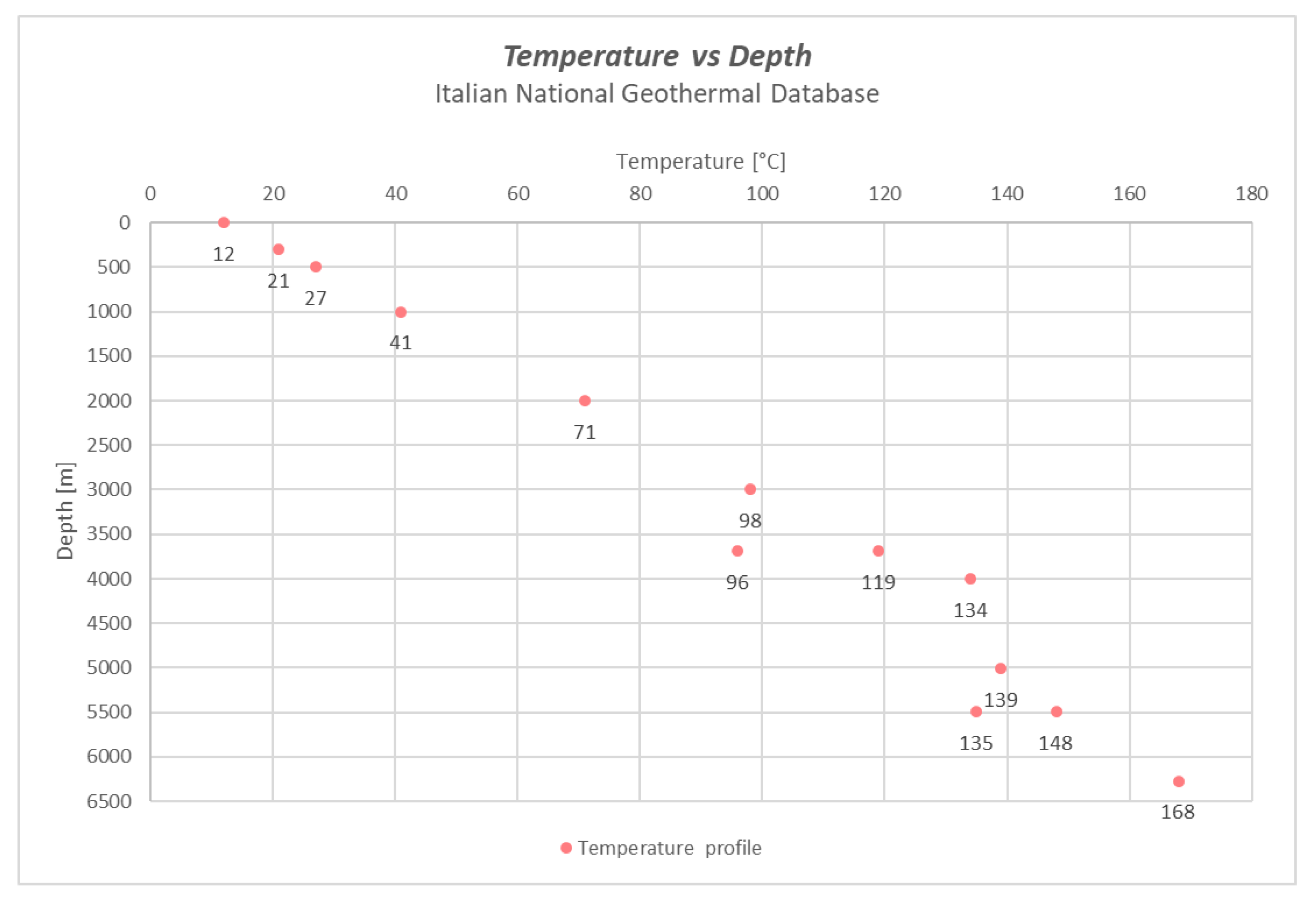
As demonstrated by information related to the litho-stratigraphic units reported in Table 1, the stratigraphic succession associated with the Trecate4 well is mainly composed of carbonate platform rocks, with the exception of a surface unit consisting of terrigenous deposits. The analysed well has a maximum depth of 6282 m and bottom-hole temperatures reaching 168 °C (Figure 2).

Table 1.
Trecate4 hydrocarbon well-lithostratigraphic profile (Villafortuna–Trecate Oilfield, Western Po Plain).

Figure 2.
Temperature data visualisation for the Trecate4 hydrocarbon well: depth (m); temperature (°C).
2.2. Closed-Loop Geothermal Energy Systems: WBHEs
In current practice, two main types of closed-loop systems have been described for harnessing geothermal energy resources by taking advantage of disused boreholes in oilfields: U-tube and coaxial double-pipe WBHE technologies [33,34].
In U-tube heat exchangers, fluid is pumped through one tube string and comes out of the other. It is by this action of flowing through the well that the fluid in the U-tube can gain heat energy from the surrounding geological formations. The gaps between internal pipes are filled with an insulating material, and the bottom hole is sealed. On the other hand, the coaxial heat exchanger comprises two concentric pipes. Circulating working fluid is injected into the outer pipe (the injection pipe), flows down to the lower part of the exchanger and is gradually warmed by heat from the rocks. After the fluid reaches the bottom hole of the well, it flows upwards through a thinner pipe, which acts as the inner pipe (the extraction pipe). Both pipes are thermally insulated, and the bottom hole is sealed. Heat exchange occurs between the geological formation and the fluid in the injection pipe and between the fluid in the injection pipe and the fluid in the extraction pipe [10].
For both closed-loop geothermal systems, the consequences of corrosion have to be considered in the selection phase of the working fluid. Due to its low cost, heat transfer and stored capacity, water represents one of the most used working fluids. Moreover, operating parameters such as the fluid flow rate and pipe diameter have to be selected in order to guarantee transient turbulent flow conditions in the subsurface, thus facilitating heat transfer from the ground to the fluid [33].
For properly evaluating the temperature profiles of the selected fluid (water) associated with both U-tube and coaxial double-pipe WBHE technologies, the models proposed below were implemented in a Python environment, identifying the best geothermal system configuration. Then, they were applied to the selected case study represented by the Trecate4 hydrocarbon well.
2.3. Heat Transfer in Coaxial WBHEs
In coaxial WBHEs, the steel downward is in contact with the hole in the well. The energy balance of the fluid in the injection pipe can be expressed with the following equation [14,35]:
where A0 and vf are the outer pipe area and fluid velocity, respectively, Tfo is the fluid temperature in the outer pipe and is the heat extraction from the formation at unit well depth (W/m) (Table 2).
Table 2.
Coaxial WBHE–geometric parameters.
Although insulation is used to prevent heat loss from the inner-pipe fluid, heat is partly transferred between the two pipes; thus, represents the heat flux from the inner pipe to the outer pipe. Therefore, the energy equation for the inner pipe can be given as follows.
By assuming steady heat transfer and constant heat flux in wellbore components (e.g., insulation, casing and cement), heat extraction from the formation can be assumed to be equal to the heat flux through the outside surface of the wellbore (interface of the wellbore and rock formation) to the injected fluid [14,35]:
where Tw is the temperature at the interface of the wellbore and the formation, kw is the heat transfer coefficient between the outer pipe fluid and wellbore exterior and Rw is the resistance between the outer pipe and surrounding rocks.
At the well bottom, the heated fluid is forced to enter and flow through the internal pipe of the coaxial WBHE. Proceeding upwards to the wellhead, heat transfer occurs only through the wall of the internal pipe. Thus, is determined by considering the temperature difference between the outer-pipe and inner-pipe fluids, as well as the estimated thermal resistance of the insulation:
where Tfi is the fluid temperature in the inner pipe, ki0 is the heat transfer coefficient between the outer pipe and inner pipe and Ri0 is the thermal resistance between the outer pipe and inner pipe.
2.3.1. Coaxial WBHE: Coefficient of Heat Exchange between Outer-Pipe Fluid and the Wellbore Exterior
In an analysis of the energy balance equation for the fluid in the outer pipe (injection pipe) of a coaxial WBHE, a proper estimate of the parameter kw is fundamental for a correct evaluation of the heat exchange between the outer-pipe fluid and the drilled geological formations.
For a coaxial WBHE, the heat exchange coefficient for the injection pipe can be expressed as the sum of heat transfer components, expressed in terms of thermal resistance values (Rw) [24]:
where Rs is a function of time that represents thermal resistance due to conductive heat transfer in the rock, Ra is the thermal resistance due to convective heat transfer in the pipe and Rc is the thermal resistance due to conductive heat transfer through the casings of the well.
In the evaluation of total thermal resistance, the conductive term prevails; consequently, thermal exchange is directly proportional to the convective transfer coefficient. Conductive thermal resistance (Rs) can be expressed as follows:
where λs (W/mK) is the thermal conductivity of the rock, and αs (m/s) is the thermal diffusivity of the rock. In Equation (6), the numerator of the argument of the natural logarithm represents the time-dependent radius of the thermal influence of the well (rs). This parameter considers the change, over time, of the heat flux into WBHE surroundings geological formations [24].
Convective thermal resistance (Ra) can be determined by the following equation:
where rc is the external radius of the external casing, and hf is the convective heat transfer coefficient, which was calculated using the Nusselt number (Nu) and a form of the Dittus–Boelter equation that assumes turbulent flow inside the tubes (Reynolds number ≥ 104) [36]:
with and .
Finally, thermal resistance to heat conduction through the casings of the well can be determined as follows:
where λi is the thermal conductivity of the rock in correspondence with the different casings of the well. Generally, due to the high thermal conductivity of the steel piping, the total thermal resistance of the casing is negligible compared to the rock’s thermal resistance.
As a result, the heat exchange coefficient kw can be correctly determined as follows [22]:
where rc = rw as the thickness of the external tube is negligible.
2.3.2. Coaxial WBHE: Coefficient of the Heat Exchange between the Outer-Pipe Fluid and the Inner Pipe
Unlike in the injection pipe, the total heat flux in the upward pipe (extraction pipe) is determined by a conductive component of the composite pipe and by two convective components: one on the internal wall and one on the external wall of the WBHE.
Consequently, the total heat exchange coefficient ki0 for the extraction pipe can be calculated as follows [22]:
where r0 is the radius of the inner pipe, d is the thicknesses of the pipe exchanger, h0 and hi are the coefficients of convective heat transfer to the inner and outer wall, respectively, and λi is the thermal conductivity of the pipe material (air and steel).
2.4. U-Tube WBHE: Thermal Resistances Model
In U-tube WBHE, the hole between the tubes and the well is filled with grout (bentonite) in order to prevent direct leakage between the ground and tubes, avoiding a connection between the ground and Earth’s subsurface.
Several approaches have been proposed for reproducing the thermal behaviour of different U-tube WBHE configurations [37]. In this work, to compute the temperature profile in the U-tube configuration using a one-dimensional heat exchange, the model with a set of equivalent thermal resistances described in [25] was applied. Six thermal resistances were considered at each depth, including the thermal properties of the ground, the grout and the pipes (Figure 3).
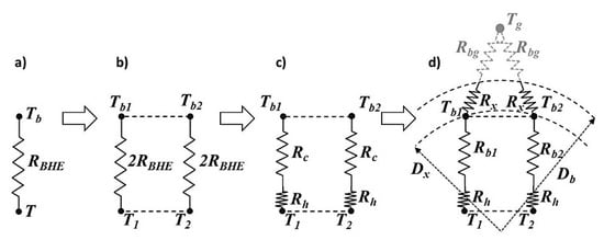
Figure 3.
Thermal resistances definition steps: (a) borehole resistance, (b) parallel borehole resistances, (c) convective and conductive resistances and (d) final resistances configuration (reproduced from [22]. Copyright Elsevier, 2014).
The thermal resistances between the grout (bentonite) and pipe depend on the overall borehole thermal resistance Rbhe. This parameter is the average thermal resistance between the fluid in the pipe and the borehole wall, and it is usually determined after experimental tests. The grout area is divided into two zones according to the pipe numbers; thus, Rbhe was also considered as divided into two parallel resistances that connected each pipe with the corresponding grout zone. This parameter can be further divided into a convective (Rh) and a conductive (Rc) term (Equation (13)):
where Rc represents conductive thermal resistance, considering the total conductive resistance between the pipes and the borehole wall. As the grout node can be located at a certain distance Dx, Rc is divided into two different resistances (Equations (14) and (15)):
where Rb represents the conductive resistance between the pipe and the considered node.
Rh is calculated by following Equation (16), where ri is the internal pipe radius, hf is the convective heat coefficient and Nu is the dimensionless Nusselt number that is calculated using Equation (9).
The Rc value is indeed estimated using a calculation method that requires the estimation of the pipe equivalent surface Seq and its diameter Deq (Equation (17)) (Table 3).
Table 3.
U-tube WBHE geometric parameters.
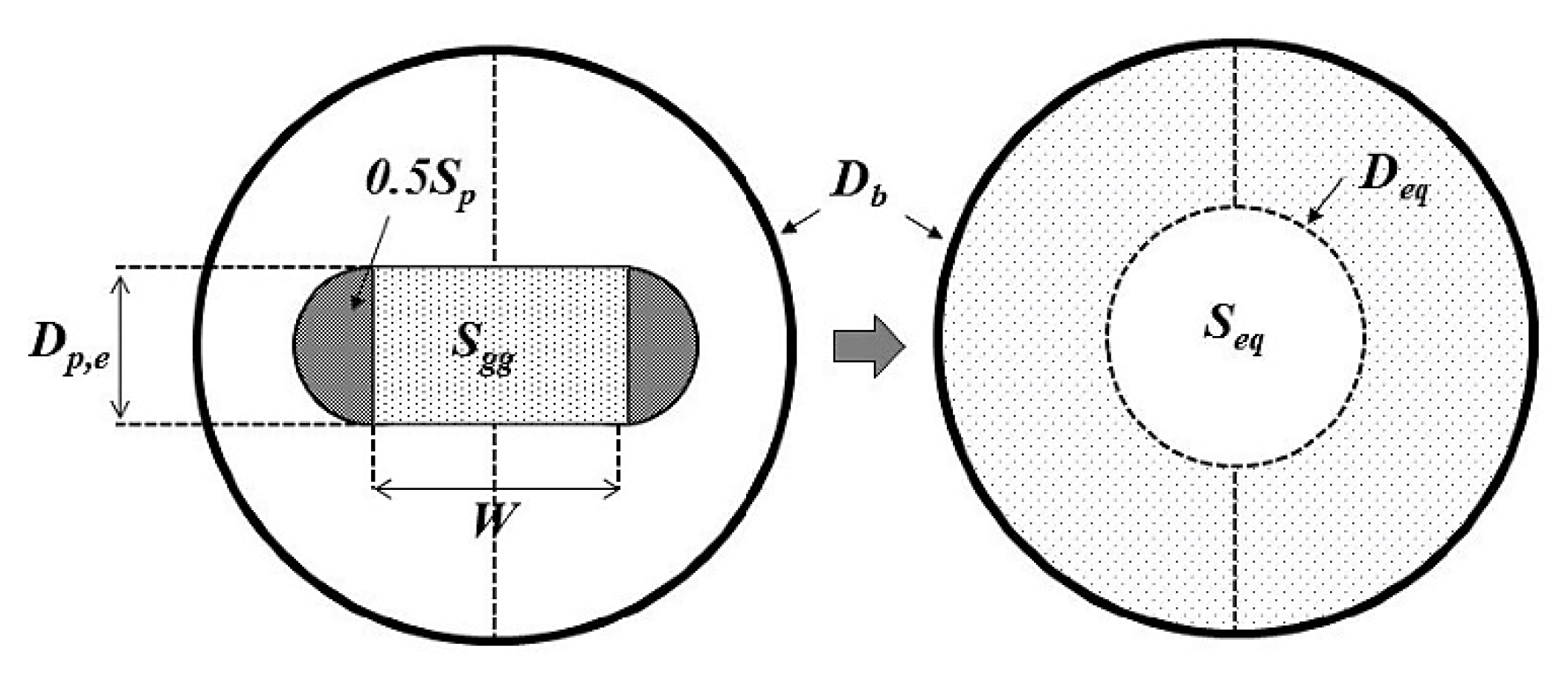
The pipe equivalent surface (Seq) can be calculated by following the approach proposed in [38], considering the sum of the areas Sgg and Sp as indicated in Figure 4. Consequently, Deq is obtained by following Equation (18).
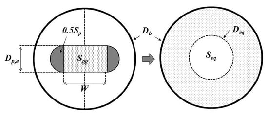
Figure 4.
Geometrical model characteristics for calculating the equivalent diameter (modified from [22]. Copyright Elsevier, 2014).
Using the equivalent diameter, the conductive thermal resistances Rb and Rx are calculated by considering a semi-cylindrical conductive heat transfer:
where kb is the borehole grout thermal conductivity.
Usually, when the pipes are near the borehole wall, Dx can be located at the same distance from the borehole wall; thus Dx = Db, and, as a consequence, the Rx part of the conductive resistance can be neglected.
Finally, the correlation as reported in Equation (6) is used for the estimation of ground thermal resistances. The total resistance value related to the analysed single tube includes convective (Ra), grout conduction (Rb + Rx) and ground resistance (Rs) terms.
2.5. WBHE Model Assumptions
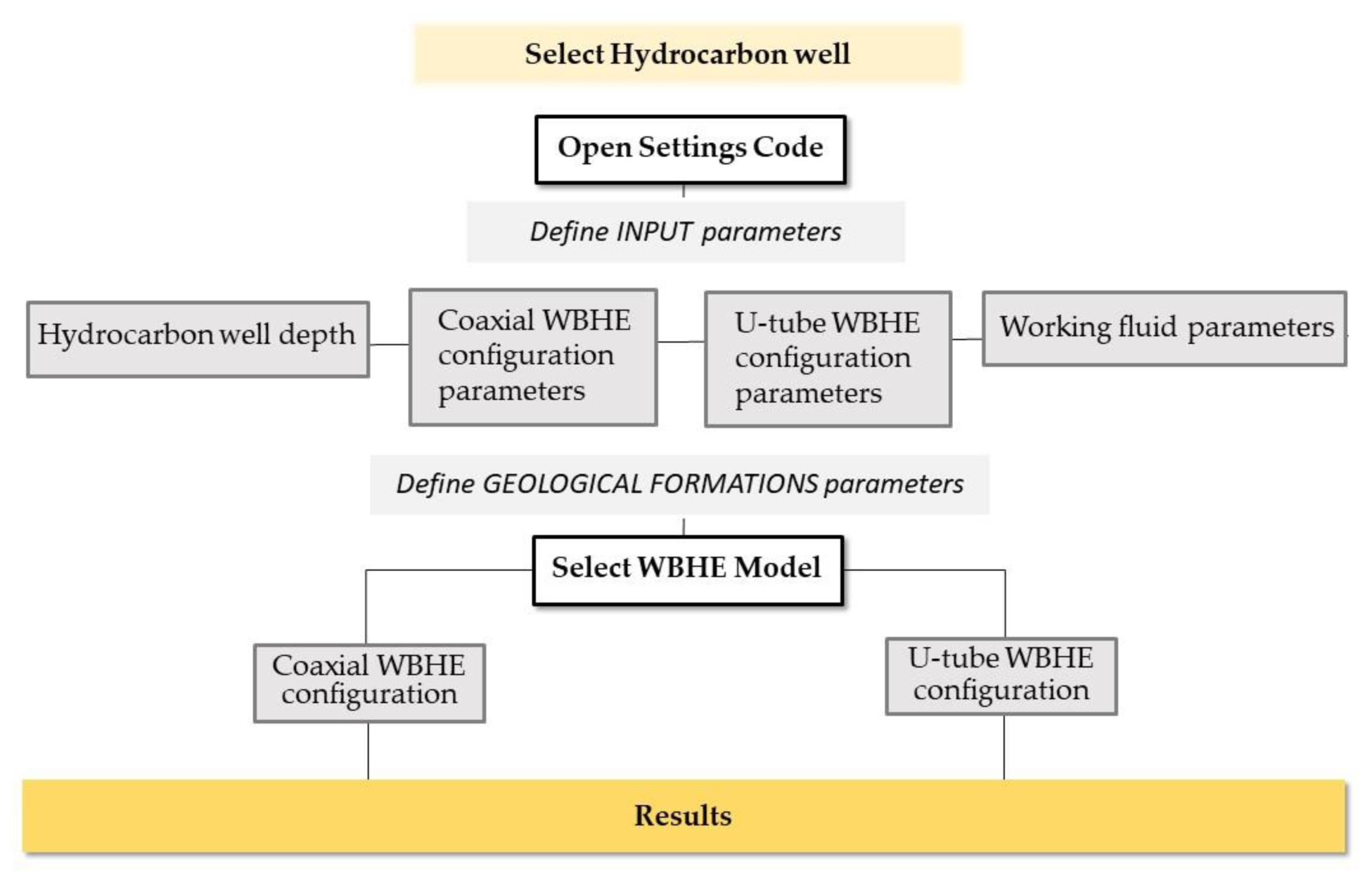
Python is a high-level programming language with an object-oriented approach described in [39]. As the Python software allows algorithms to be solved easily, it was used to perform the analysis of the WBHEs by implementing the described models (coaxial and U-tube-WBHE models) in different codes that have the structure illustrated in Figure 5.
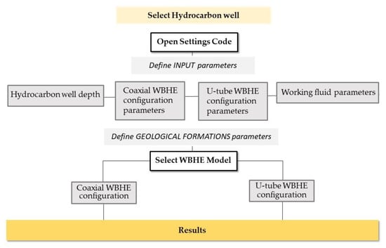
Figure 5.
Python codes simplified research flowchart.
According to both selected models, the propagation of heat in the reservoir occurs through conduction; the propagation of heat inside the wellbore tubes takes place through conduction and convection phenomena. The reservoir model was built by assuming a single well located at the center of a circular reservoir.
The temperature profile in the radial direction was assumed to be constant. Therefore, there was no temperature gradient in the annulus or the inner tube. Due to the turbulent flow, enhanced mixing phenomena occurred, which decreased the radial gradient. The temperature changed only in the annulus and in the vertical direction of the inner tube. Consequently, the temperature profile was unidirectional (vertical temperature profile).
The properties of the heat carrier fluid were assumed to be constant. As the fluid used in this study was water (100 °C, 2 bar), no variations occurred due to pressure or/and temperature gradients.
The analytical models were built under steady-state conditions; there were no temperature variations over time, with each point in the tubes (annulus and inner tube) maintaining the same temperature for the lifecycle of the system. In addition, the models considered the resistance associated with tube thickness to be negligible. The tube material had very high conductivity (15 W/mK), so its resistance could be considered small compared to the other resistances in the system. For the estimation of resistance associated with the rock (see Equation (6)), the time value used was 3 years. The analysed system, in the period preceding the three years (1–3 years), turns out to ensure larger heat exchange phenomena with the possibility of causing overestimation in energy performances.
Considering the U-tube configuration, heat exchange was assumed to take place in an area that was half the area of the casing pipe, while the interaction between the downward and upward tubes was neglected.
Both proposed analytical models follow the path of the working fluid with an approach that could be called step-by-step. In detail, they considered intervals of length dz in which the inlet and outlet temperatures were calculated by solving the energy balance equation for each considered volume dv. For the estimation of the energy exchange in the radial direction, the mean value of the temperature in the volume dv was used and calculated by using the arithmetic mean. All energy exchanged in the radial direction in the volume dv was absorbed by water (selected working fluid).
3. Results and Discussion
3.1. Influence of Ground Thermal Properties on Heat Exchange Phenomena
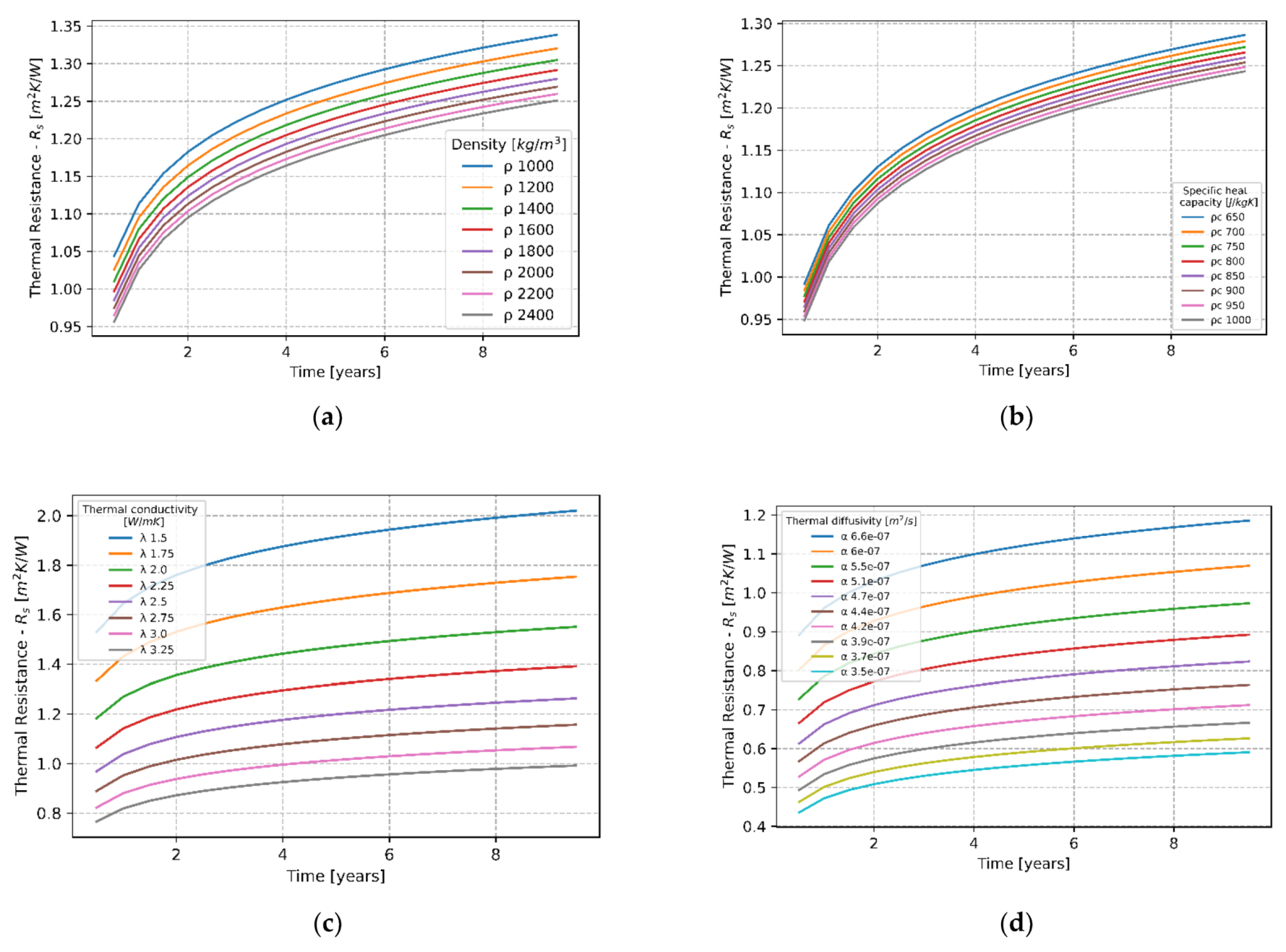
During a preliminary phase of analysis to understand the extent of the variation in thermal outputs associated with the considered WBHE technologies, a sensitivity analysis was performed on the different underground thermal properties. Starting from the analysis of Equation 6, describing the thermal resistance due to conductive heat transfer in the rock, we proceeded to the graphic elaboration of curves of the variation of the resistance parameter over time with the values of density (ρ), volumetric heat capacity (ρcs) and the thermal conductivity of rock (λs) change (Figure 6a–c). Moreover, an evaluation of the impact of thermal diffusivity value (α) variation in the Rs parameter was reported in Figure 6d.
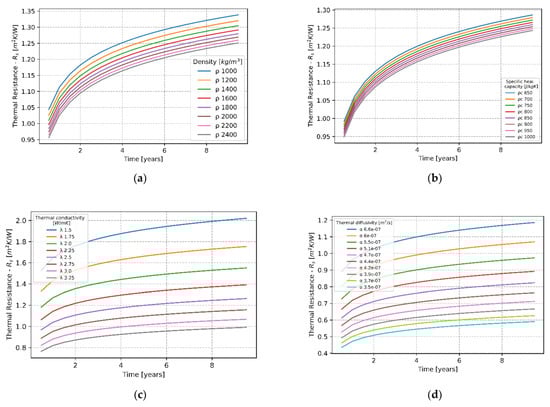
Figure 6.
Soil resistance over time with different ground density (ρ–kg/m3) (a); specific heat (pcs rock–J/kg/K) (b); conductivity (λs–W/mK) (c); thermal diffusivity (α) (d).
Different input values associated with thermal properties subject to the performed sensitivity analysis were chosen in order to properly cover a significant range for the types of geological formations involved (sedimentary rocks) [28,29]. The proposed analysis has been useful for understanding how thermal outputs change as a consequence of the variations in the input data of ground thermal properties. The ground thermal properties directly influence ground resistance values (Rs), as highlighted in Equation (6). The highest wellhead temperature variation is caused by changes in thermal conductivity values. The implementation in the proposed models of proper values of geological formation thermal properties (case studies-specific stratigraphy) turns out to be fundamental for improving the quality of the performed heat exchange analysis.
3.2. WBHE Configurations
The temperature profiles associated with the described Coaxial and U-tube WBHE system configurations were obtained by making use of the specific ground properties of the selected case study (Trecate4 hydrocarbon well) reported in Table 1. Values relating to the thermal properties of the different rock formations have been attributed by following those proposed in [31,32] (Table 1). Moreover, the thermal conductivity value of the insulating material was set to 0.025 W/mK. Working fluid inlet flow rate (water) and temperature values were considered as 3.0 kg/s and 50 °C, respectively. Selected inlet temperature represents a typical value for direct applications such as production cycles in manufacturing and agricultural districts [1]. Subsequently, an analysis was conducted on the term vector fluid temperature at the outlet as the inlet flow rate varies.
For the coaxial WBHE configuration, the sizings of the inner and outer tubes, as well as the final casing size, were fixed according to the values proposed in Table 4a. The characteristic configuration of the U-Tube WBHE is shown in Table 4b.
Table 4.
(a). Coaxial WBHE tube sizing. ID: internal diameter; OD: external diameter [24]; (b). U-tube WBHE parameters [25].
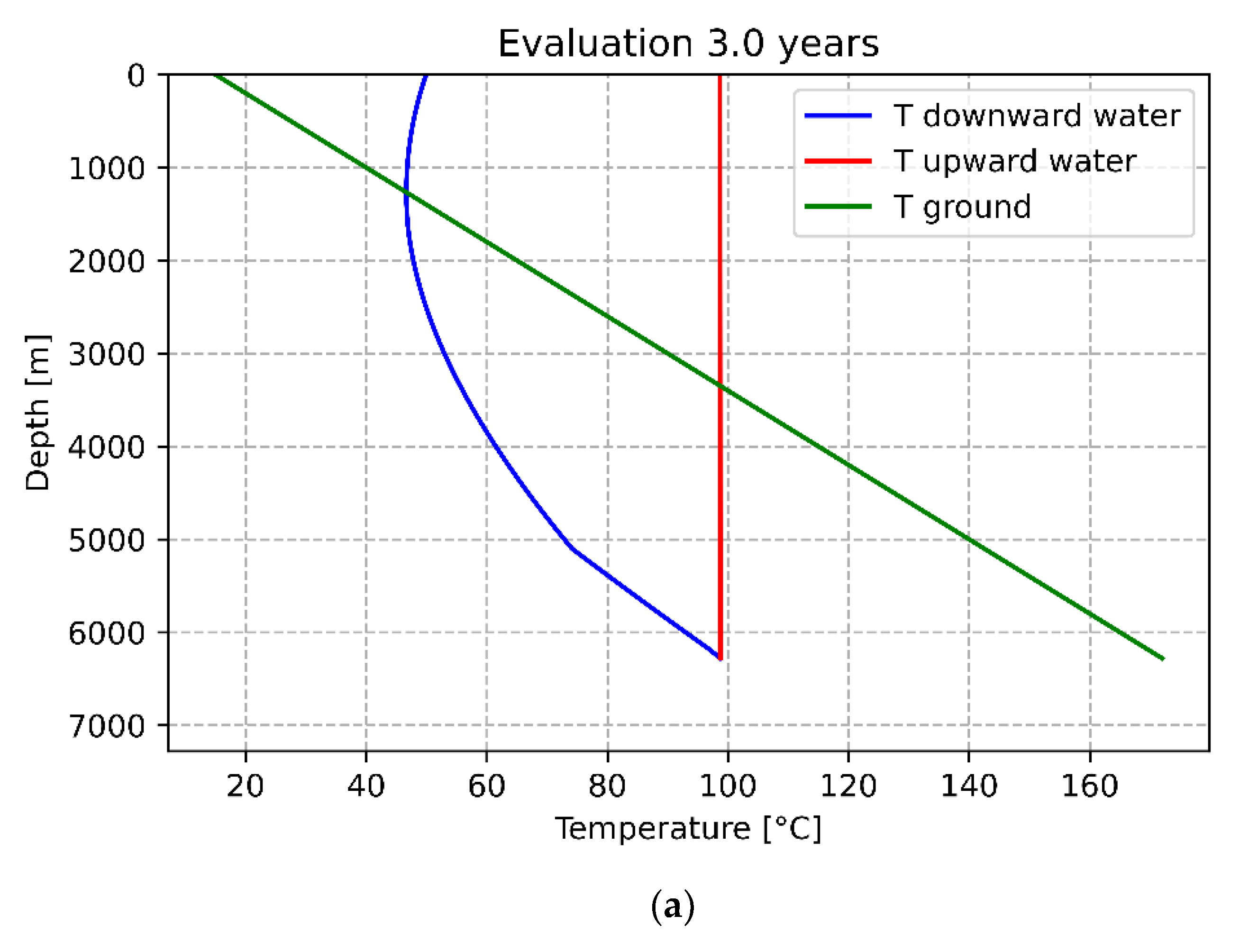
For the Coaxial WBHE configuration, over the first 1200 m downwards, the selected thermo-vector fluid decreases in temperature. As the downward profile line crosses the underground temperature line, the real heating process begins, and the ground contribution became positive. Due to the presence of the insulating material, the heat exchange coefficient between tubes turns out to be low, and the increase in working fluid temperature can be associated with the ground (Figure 7a).
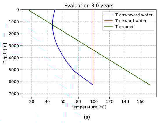
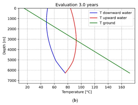
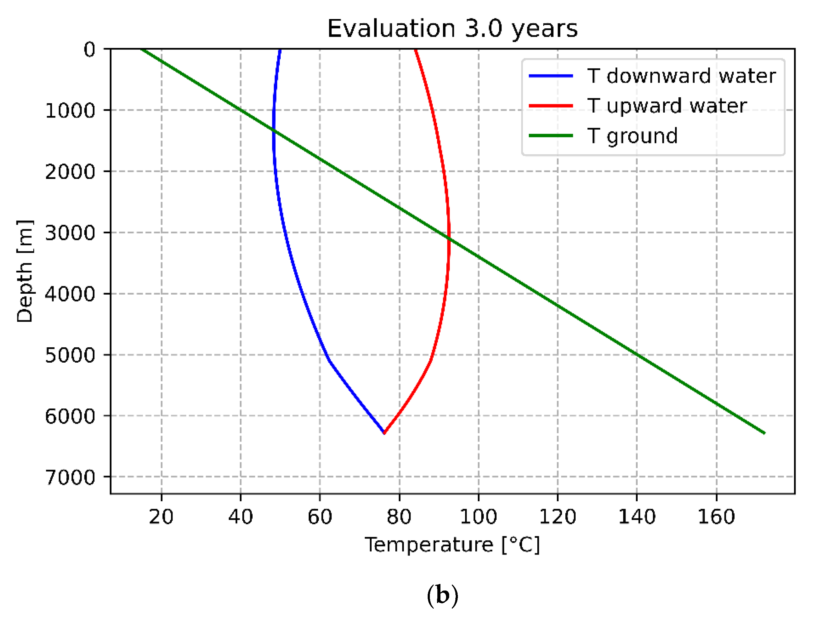
Figure 7.
Temperature profile associated with the coaxial WBHE (a) and U-tube WBHE (b) configurations considering site-specific stratigraphy.
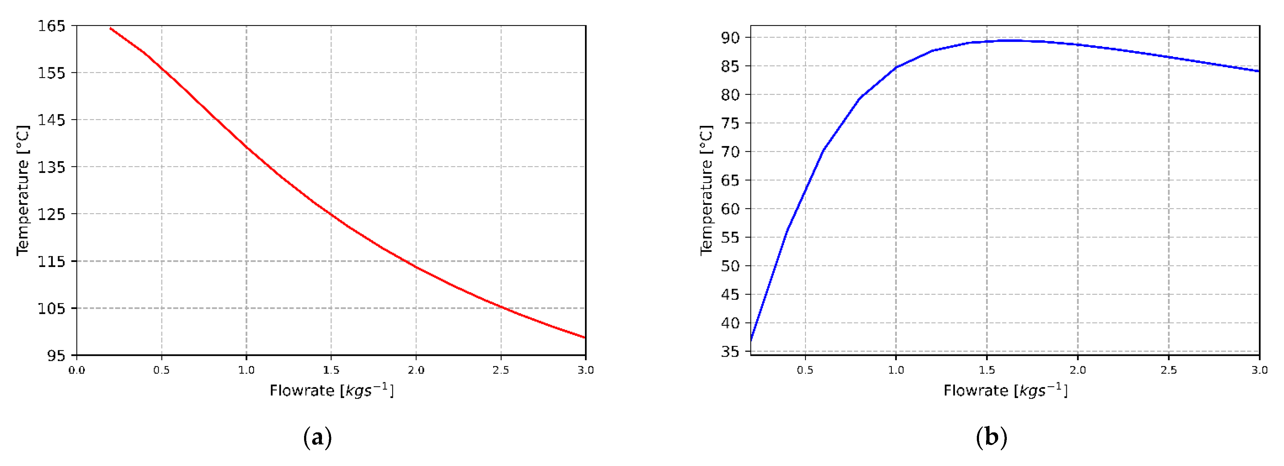
In coaxial WBHE, the maximum recorded temperature is equal to 98.6 °C. The inlet flow rate strongly influences the temperature of the wellhead thermal fluid and, consequently, the heat power amount. As observed in Figure 8a, by considering inlet flow rate values between 0.5 and 1 kg/s, the output fluid temperature increases up to about 155 °C. Consequently, for the specific case study and associated plant configuration, it is possible to identify an inlet flow rate value that potentially allows an optimization of the wellhead temperature.
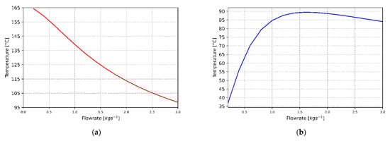
Figure 8.
Wellhead temperature as the flow rate value changes: (a) Coaxial WBHE; (b) U-tube WBHE.
Considering the U-tube WBHE configuration and its associated temperature profile, it was possible to identify how the ground’s contribution was responsible for a sizable temperature variation, both in the downward and upward tube. Over the first borehole section (approximately 1200 m), the fluid was cooled by the ground. Subsequently, as the temperature profile line crossed the underground temperature line, the trend was inverted, and the heat carrier fluid temperature began to increase, reaching a maximum temperature value of 84 °C (Figure 7b).
As for the considered coaxial-WBHE configuration, the wellhead thermal fluid temperature in U-tube WBHE changes as the input flow rate parameter varies; these were estimated (Figure 8b).
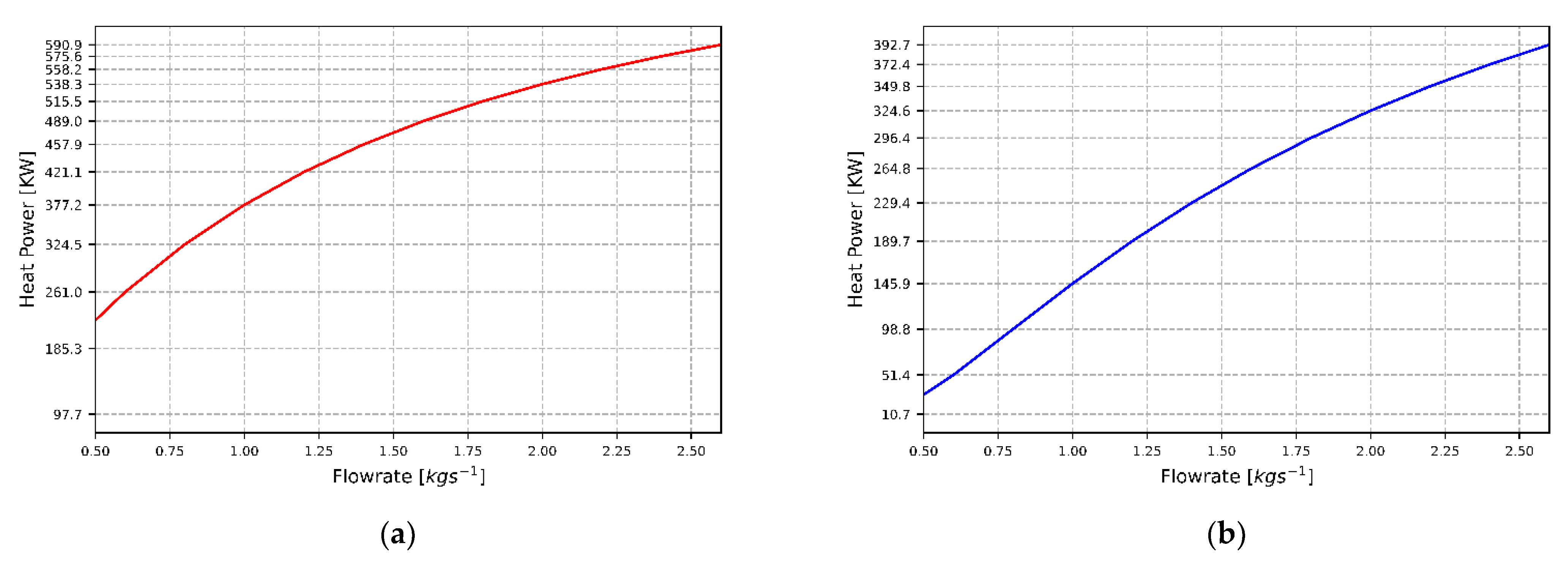
For a flow rate value of 1.5 kg/s, the fluid reaches the surface at a maximum temperature of 89.4 °C. For higher flow rate values, the wellhead temperatures recorded are progressively lower. Using the fixed inlet working fluid temperature (50 °C) and the estimated maximum fluid temperature at the outlet for the different configurations, thermal power values were evaluated for 616.7 KW (98.6 °C-Coaxial WBHE) and 427.9 KW (84 °C-U-tube WBHE) (Figure 9a,b).
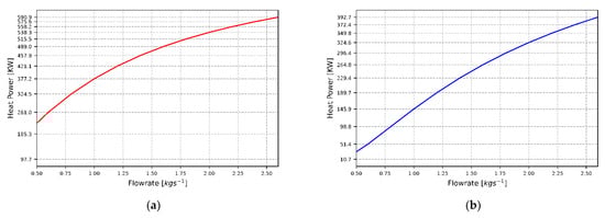
Figure 9.
Heat Power as the flow rate value changes: (a) Coaxial WBHE; (b) U-tube WBHE.
Considering a cascading exploitation mode of the heat accumulated by the working fluid in Trecate4 WBHEs, it is possible to hypothesize a multi-variant and comprehensive use of the resource. The outflow temperatures of working fluids at the wellhead for Coaxial and U-tube WBHEs are 98.6 °C and 84 °C, respectively, which allows it to progressively be used for greenhouse heating (100–80 °C), food industry (80–70 °C), animal breeding (60 °C), biomass and agricultural cultures (<50 °C).
The utilization of the geothermal resources at cascade levels is indeed identified as a series of sequential operations by integrating different technologies for distribution and use of thermal energy, drying and dehydration processes, recreational uses and any other direct use [40].
By analyzing the characteristics of modern production plants in the agricultural field of central Italy regions, according to what was reported in [41], the average daily temperature values indicated for plants in greenhouses cultivations (horticultural and flower species) are in the range of 30–15 °C, with variations at daily and seasonal scales. Geothermal energy derived from a converted geothermal well can contribute to reducing the consumption of fuel used for heating and is strongly dependent on the production techniques adopted, the species and varieties cultivated and the control strategies of the climatic conditions adopted.
4. Conclusions
Geothermal energy resources associated with disused hydrocarbon wells in Italian oilfields represent a considerable source of renewable energy. As a type of energy stored in subsurface geological formations and associated with hydrocarbons in oilfields, geothermal energy needs to be extracted before final utilisations. Closed-loop technologies represent an effective alternative in contrast to conventional open-loop geothermal systems as heat carrier fluids circulate inside wellbore heat exchangers (WBHEs), while no ground fluids are extracted from surrounding rocks.
In this paper, with the main aim to propose a simplified tool for the definition of the best closed-loop system that allows maximizing heat recovered from a selected hydrocarbon well, two different simplified heat exchange models (U-tube and coaxial WBHE) have been described and implemented in a Python programming language. Both the site-specific geological and thermo-physical properties of a selected study case (Trecate4 hydrocarbon well) were properly considered for the computer analyses carried out.
The implementation of site-specific stratigraphy in the performed models was fundamental as it contributes to improving the amount of heat exchange phenomena. Moreover, by analysing the results obtained as output from the developed models (U-tube and Coaxial), the coaxial WBHE technology turned out to be better performing. In detail, from the comparison between the temperature profiles obtained by fixing an inlet mass flow value of 3 kg/s, it can be found that the outlet fluid temperature for the coaxial configuration (98.6 °C) is higher than that estimated for the U-tube version (84 °C). Even for variable flow rate values, an ever-higher output temperature for the coaxial configuration is recorded. Thermal powers are consequently higher. The outflow temperatures of geothermal water at the wellhead for both Coaxial and U-tube WBHEs could progressively be used for greenhouse heating (100–80 °C), food industry (80–70 °C), animal breeding (60 °C), biomass and agricultural cultures (<50 °C).
An analysis of the possibility of having phase change (evaporation) of the working fluid and the role in heat transfer and performance of extracting heat from abandoned wells of intraformational flows needs to be performed in order to further improve the accuracy of models. The proposed approach covering the described simplified models represents a useful methodological tool that allows for preliminary studies of the possibility of a selected Italian hydrocarbon well to be converted into a geothermal one by using WBHE technologies.
Funding
This research received no external funding.
Institutional Review Board Statement
Not applicable.
Informed Consent Statement
Not applicable.
Data Availability Statement
Information related to Italian hydrocarbon wells and temperature data are available at the web page of the National Mining Office of the Italian Ministry for Economic Development (MISE) and the Italian National Geothermal Database.
Conflicts of Interest
The author declares no conflict of interest.
Abbreviations
| Abbreviations Parameter | Symbol | Unit of Measure |
| Volumetric heat capacity of the fluid | ρcf | (J m−3 K−1) |
| Volumetric heat capacity of the rock | ρcs | (J m−3 K−1) |
| Density | ρ | (Kgm−3) |
| Thermal conductivity of the fluid | λf | (W m−1 K−1) |
| Thermal conductivity of the rock | λs | (W m−1 K−1) |
| Heat conductivity of the porous media | λm | (W m−1 K−1) |
| Heat conductivity of the pipe material | λi | (W m−1 K−1) |
| Viscosity | μ | (kgm−1s−1) |
| Thermal diffusivity of the rock | αs | (ms−1) |
| Radius of thermal influence | rs | (m) |
| Temperature of the rock | T | (°C) |
| Temperature at the interface of wellbore/formation | Tw | (°C) |
| Fluid temperature in the outer pipe | Tfo | (°C) |
| Fluid temperature in the inner pipe | Tfi | (°C) |
| Temperature of the environment at the inlet | Tei | (°C) |
| Temperature of the environment at the surface | Tes | (°C) |
| Time | t | (h) |
| Flow rate | q | (m3h−1) |
| Fluid velocity | vf | (ms−1) |
| Heat transfer coefficient–outer pipe fluid and wellbore outside | kw | (Wm−2K−1) |
| Heat transfer coefficient–the outer pipe and inner pipe | ki0 | (Wm−2K−1) |
| Convective heat transfer coefficient | hf | (m−2 K−1) |
| Coefficient of convective heat transfer to the inner wall | h0 | (Wm−2K−1) |
References
- Kaczmarczyk, M.; Tomaszewska, B.; Operacz, A. Sustainable Utilization of Low Enthalpy Geothermal Resources to Electricity Generation through a Cascade System. Energies 2020, 13, 2495. [Google Scholar] [CrossRef]
- Lund, J.W.; Toth, A.N. Direct utilization of geothermal energy 2020 worldwide review. Geothermics 2021, 90, 101915. [Google Scholar] [CrossRef]
- Gestore dei Servizi Energetici S.p.A. RAPPORTO STATISTICO 2018: Energia da Fonti Rinnovabiliin Italia. 2018, p. 168. Available online: https://www.gse.it/servizi-per-te/news/gse-pubblicato-il-rapporto-statistico-2018 (accessed on 1 September 2021).
- Soldo, E.; Alimonti, C.; Scrocca, D. Geothermal Repurposing of Depleted Oil and Gas Wells in Italy. Proceedings 2020, 58, 9. [Google Scholar] [CrossRef]
- Cataldi, R.; Mongelli, F.; Squarci, P.; Taffi, L.; Zito, G.; Calore, C. Geothermal ranking of Italian territory. Geothermics 1995, 24, 115–129. [Google Scholar] [CrossRef]
- Montanari, D.; Minissale, A.; Doveri, M.; Gola, G.; Trumpy, E.; Santilano, A.; Manzella, A. Geothermal resources within carbonate reservoirs in western Sicily (Italy): A review. Earth-Sci. Rev. 2017, 169, 180–201. [Google Scholar] [CrossRef]
- Trumpy, E.; Botteghi, S.; Caiozzi, F.; Donato, A.; Gola, G.; Montanari, D.; Pluymaekers, M.P.D.; Santilano, A.; van Wees, J.D.; Manzella, A. Geothermal potential assessment for a low carbon strategy: A new systematic approach applied in southern Italy. Energy 2016, 103, 167–181. [Google Scholar] [CrossRef]
- Trumpy, E.; Manzella, A. Geothopica and the interactive analysis and visualization of the updated Italian National Geothermal Database. Int. J. Appl. Earth Obs. Geoinf. 2017, 54, 28–37. [Google Scholar] [CrossRef]
- Alimonti, C.; Conti, P.; Soldo, E. Producing geothermal energy with a deep borehole heat exchanger: Exergy optimization of different applications and preliminary design criteria. Energy 2021, 220, 119679. [Google Scholar] [CrossRef]
- Wang, K.; Yuan, B.; Ji, G.; Wu, X. A comprehensive review of geothermal energy extraction and utilization in oilfields. J. Pet. Sci. Eng. 2018, 168, 465–477. [Google Scholar] [CrossRef]
- Liu, X.; Falcone, G.; Alimonti, C. A systematic study of harnessing low-temperature geothermal energy from oil and gas reservoirs. Energy 2018, 142, 346–355. [Google Scholar] [CrossRef] [Green Version]
- Falcone, G.; Liu, X.; Okech, R.R.; Seyidov, F.; Teodoriu, C. Assessment of deep geothermal energy exploitation methods: The need for novel single-well solutions. Energy 2018, 160, 54–63. [Google Scholar] [CrossRef] [Green Version]
- Kharseh, M.; Al-Khawaja, M.; Hassani, F. Optimal utilization of geothermal heat from abandoned oil wells for power generation. Appl. Therm. Eng. 2019, 153, 536–542. [Google Scholar] [CrossRef]
- Blank, L.; Meneses Rioseco, E.; Caiazzo, A.; Wilbrandt, U. Modeling, simulation, and optimization of geothermal energy production from hot sedimentary aquifers. Comput. Geosci. 2021, 25, 67–104. [Google Scholar] [CrossRef]
- Dussel, M.; Lüschen, E.; Thomas, R.; Agemar, T.; Fritzer, T.; Sieblitz, S.; Huber, B.; Birner, J.; Schulz, R. Forecast for thermal water use from Upper Jurassic carbonates in the Munich region (South German Molasse Basin). Geothermics 2016, 60, 13–30. [Google Scholar] [CrossRef]
- Nian, Y.L.; Cheng, W.L. Insights into geothermal utilization of abandoned oil and gas wells. Renew. Sustain. Energy Rev. 2018, 87, 44–60. [Google Scholar] [CrossRef]
- Kamila, Z.; Kaya, E.; Zarrouk, S.J. Reinjection in geothermal fields: An updated worldwide review 2020. Geothermics 2021, 89, 101970. [Google Scholar] [CrossRef]
- Perez Donoso, P.I.; Rojas, A.E.O.; Meneses Rioseco, E. Bilinear pressure diffusion and termination of bilinear flow in a vertically fractured well injecting at constant pressure. Solid Earth 2020, 11, 1423–1440. [Google Scholar] [CrossRef]
- Wight, N.M.; Bennett, N.S. Geothermal energy from abandoned oil and gas wells using water in combination with a closed wellbore. Appl. Therm. Eng. 2015, 89, 908–915. [Google Scholar] [CrossRef]
- Wang, Y.; Bu, X. A novel method of acquiring geothermal energy from unconsolidated sandstone reservoir by multi-directional wells deep borehole heat exchanger. Case Stud. Therm. Eng. 2021, 26, 101157. [Google Scholar] [CrossRef]
- Zarrouk, S.J.; Moon, H. Efficiency of geothermal power plants: A worldwide review. Geothermics 2014, 51, 142–153. [Google Scholar] [CrossRef]
- Kujawa, T.; Nowak, W.; Stachel, A.A. Utilization of existing deep geological wells for acquisitions of geothermal energy. Energy 2006, 31, 650–664. [Google Scholar] [CrossRef]
- Bu, X.; Ma, W.; Gong, Y. Electricity generation from abandoned oil and gas wells. Energy Sources Part A Recover. Util. Environ. Eff. 2014, 36, 999–1006. [Google Scholar] [CrossRef]
- Alimonti, C.; Soldo, E. Study of geothermal power generation from a very deep oil well with a wellbore heat exchanger. Renew. Energy 2016, 86, 292–301. [Google Scholar] [CrossRef]
- Ruiz-calvo, F.; De Rosa, M.; Acuña, J.; Corberán, J.M.; Montagud, C. Experimental validation of a short-term Borehole-to-Ground (B2G) dynamic model. Appl. Energy 2015, 140, 210–223. [Google Scholar] [CrossRef] [Green Version]
- Bertello, F.; Fantoni, R.; Franciosi, R.; Gatti, V.; Ghielmi, M.; Puglise, A. From thrust-and-fold belt to foreland: Hydrocarbon occurrences in Italy. Pet. Geol. Conf. Proc. 2010, 7, 113–126. [Google Scholar] [CrossRef]
- Fantoni, R.; Galimberti, R.; Ronchi, P.; Scotti, P. Po Plain Petroleum Systems: Insights from Southern Alps Outcrops (Northern Italy)*. Search Discov. Artic. 2011, 20120, 1–7. [Google Scholar]
- Bello, M.; Fantoni, R. Deep oil plays in Po Valley: Deformation and hydrocarbon generation in a deformed foreland. World Pet. 2002, 14, 18. [Google Scholar]
- Gizzi, M.; Taddia, G.; Russo, S. Lo Reuse of decommissioned hydrocarbon wells in italian oilfields by means of a closed-loop geothermal system. Appl. Sci. 2021, 11, 2411. [Google Scholar] [CrossRef]
- Cazzini, F.F. The history of the upstream oil and gas industry in Italy. Geol. Soc. Spec. Publ. 2018, 465, 243–274. [Google Scholar] [CrossRef]
- Di Sipio, E.; Galgaro, A.; Destro, E.; Giaretta, A.; Chiesa, S.; Manzella, A.; VIGOR Team. Thermal Conductivity of Rocks and Regional Mapping. In Proceedings of the European Geothermal Congress 2013, Pisa, Italy, 3–7 June 2013. [Google Scholar]
- Pasquale, V.; Gola, G.; Chiozzi, P.; Verdoya, M. Thermophysical properties of the Po Basin rocks. Geophys. J. Int. 2011, 186, 69–81. [Google Scholar] [CrossRef] [Green Version]
- Lo Russo, S.; Gizzi, M.; Taddia, G. Abandoned oil and gas wells exploitation by means of closed-loop geothermal systems: A review. Geoing. Ambient. Min. 2020, 160, 3–11. [Google Scholar] [CrossRef]
- Wang, S.; Yan, J.; Li, F.; Hu, J.; Li, K. Exploitation and utilization of oilfield geothermal resources in China. Energies 2016, 9, 798. [Google Scholar] [CrossRef] [Green Version]
- Hasan, A.; Kabir, S. Fluid Flow and Heat Transfer in Wellbores, 2nd ed.; Society of Petroleum Engineers: Richardson, TX, USA, 2018. [Google Scholar]
- Davis, A.P.; Michaelides, E.E. Geothermal power production from abandoned oil wells. Energy 2009, 34, 866–872. [Google Scholar] [CrossRef]
- Yang, H.; Cui, P.; Fang, Z. Vertical-borehole ground-coupled heat pumps: A review of models and systems. Appl. Energy 2010, 87, 16–27. [Google Scholar] [CrossRef]
- Pasquier, P.; Marcotte, D. Short-term simulation of ground heat exchanger with an improved TRCM. Renew. Energy 2012, 46, 92–99. [Google Scholar] [CrossRef]
- van Rossum, G. Python tutorial, Technical Report CS-R9526; Centrum voor Wiskunde en Informatica: Amsterdam, The Netherlands, 1995. [Google Scholar]
- Rubio-Maya, C.; Ambríz Díaz, V.M.; Pastor Martínez, E.; Belman-Flores, J.M. Cascade utilization of low and medium enthalpy geothermal resources—A review. Renew. Sustain. Energy Rev. 2015, 52, 689–716. [Google Scholar] [CrossRef]
- ARSIA. Uso Razionale Delle Risorse nel Florovivaismo: I Fabbisogni Energetici; Quadrerno ARSIA: Florence, Italy, 2003. [Google Scholar]

Publisher’s Note: MDPI stays neutral with regard to jurisdictional claims in published maps and institutional affiliations. |
© 2021 by the author. Licensee MDPI, Basel, Switzerland. This article is an open access article distributed under the terms and conditions of the Creative Commons Attribution (CC BY) license (https://creativecommons.org/licenses/by/4.0/).