1. Introduction
Carbon fiber reinforced polymers (CFRP) are a new material with high strength and corrosion resistance. They are favored by aviation and automobile manufacturing companies because of their good mechanical properties and light weight. However, it is difficult to cut and drill them by traditional mechanical processing methods, and problems such as material delamination and burrs are prone to occur when processing CFRP, which seriously restricts the wide application of CFRP [
1]. As a non-contact advanced processing technology, laser processing technology has great application potentials in CFRP processing [
2]. However, due to the sensitivity of the resin matrix to heat input, and the huge difference in the thermodynamic properties of carbon fiber and resin, etc., it is very easy to produce a heat affected zone (HAZ) when laser processing CFRP [
3]. The presence of a heat affected zone seriously affects the static strength of CFRP [
4]. At the same time, due to the characteristics of the Gaussian beam, laser drilling is prone to tapering, which is more obvious when drilling deep holes [
5]. Laminates are increasingly utilized in the aerospace and engineering fields for their high stiffness, high strength, and low weight. In recent years, much research on laser processing of composite materials has been conducted [
6]. The surface treatment of fiber can significantly improve the properties of the fiber-matrix interface, thus improving the properties of composite materials [
7,
8,
9]. During the processing, carbon floc and fiber burr always occur due to the thermodynamics damage [
10,
11,
12]. As a result, the mechanism research focusing on laser interact with CFRP is an urgent issue which needs to be studied for the processing industry. The structure of CFRP material normally takes the layered braided structural [
13]. Carbon fiber has relatively high thermal conductivity along the axis of symmetry, which is 10 times higher than carbon fiber perpendicular to the axis of symmetry and about 200 times higher than the matrix material [
14]. Thermal damage is a direct result of the large difference in thermal properties between carbon fiber and epoxy matrix [
15,
16,
17,
18]. In fact, as a matrix, the polymers show a low absorptivity at the wavelength range of about 1μm [
18,
19]. In addition, the energy required to vaporize or sublimate the carbon fiber is more than one order of magnitude higher than the matrix [
20].
Cenna et al. simulated the width of the upper and lower cut, and the mass transfer and energy transfer of the laser cut CFRP [
21]. Cheng and others used a numerical finite difference heat flow model to predict and analyze the shape and size of the punch hole under given laser conditions [
22]. Their simulation results are in good agreement with the experimental results. Boley et al. studied a model of laser interaction with CFRP. The absorption rate, absorption depth, angle of reflected light, and the enhancement of light energy in the material were determined by ray tracing model [
23]. At the same time, the macro model is used to study the overall damage effect. The results show that the ray tracing model plays a decisive role in the parameters of the two models. In the above research, the macro phenomena of laser processing of 3D CFRP are the main, and there is no much attention to the temperature rise details of laser target.
In order to study the temperature rise of the CFRP irradiated by laser, we aimed to gain insight into the mechanism of the morphology performance when long pulse laser interacts with CFRP composites. Our analysis is based on the anisotropic properties, while modeling, simulation, and the experimental comparison are discussed as follows:
- (1)
The ablation of CFRP laminates under different laser conditions was carried out. The simulation results show the elliptical morphology which agrees with the experimental finding. The HAZ and depth of composites behave differently by various parameters such as laser pulse number and fluence.
- (2)
Based on the crystal lattice dynamics theory, the mechanism of surface ablation on CFRP has been analyzed focusing on the thermal vibrations of the lattice. Furthermore, the unexpected tapered bore under the surface was discussed subsequently.
2. Materials and Methods
The experimental setup is shown in
Figure 1. The experimental system consists of laser emission, temperature measurement, and surface topography measurement. The laser emission and detection system includes a millisecond pulse laser, Maler 10, spectrometer, laser energy meter, and focusing lens. The wavelength of the millisecond laser is 1064 nm, the pulse frequency is 10 Hz, the pulse width is 0.5–3 ms, and the energy is 0.5–10 J. After passing through the beam splitter, the laser is partially reflected to the probe of the energy meter, which measures the laser energy in real time to calculate the target laser energy; most of the other lasers focus on the surface of the composite through the focusing lens to damage the material. In order to measure the surface temperature of the material, a kmga high-speed thermometer and temperature probe are used to measure the temperature of the laser action area on the material surface. The time step of the thermometer is 10 μs. The temperature measurement range is 350–3500 °C. After the laser treatment, an alicona three-dimensional surface measurement instrument was used to measure the surface damage morphology. In the experiment, the fiber/epoxy resin composite was fixed on a three-dimensional translation table, which was perpendicular to the laser. In the experiment, the surface size of the sample material is 50 × 50 mm, 1 mm, 2 mm, or 5 mm in thickness. The fiber diameter is 0.2 mm. A composite material is usually defined as a combination of two or more different materials which have different physical and chemical properties. Thus, composite materials may possess the superior properties of both components. Generally, in the carbon fiber reinforced polymer, with fiber wrapped by the resin matrix, is the main load-bearing component of the material [
13,
14]. At the same time, the resin is the load transfer element, which also plays the role of protecting the whole structure [
15].
Moreover, for the physical model, based on the anisotropic structure of fiber/epoxy resin composite material, the heat conduction equation of the long-pulsed laser interacting with it can be written as follows:
where,
is the density, and
is the specific heat of the material,
(i, j = 1,2,3) is the thermal conductivity component of the material, and they constitute a second-order tensor
:
From the Onsager principle of irreversible process thermodynamics, the thermal conductivity component
is subject to reciprocity:
In addition, according to irreversible thermodynamics, the coefficients
are all positive:
And the size of the coefficient
is limited by the following requirements:
is the heat source term of long-pulsed laser, whose expression can be written as:
where, E is the single pulse energy of the laser,
is the laser spot radius located on the material surface,
is the pulse width of the laser
,
are reflection coefficient and absorption coefficient of material,
is time distribution of laser beam, respectively. They are defined as:
The initial condition is the temperature field distribution when the laser does not act on the material
where
is the initial condition of room temperature,
. In the process of laser cutting CFRP, there are thermal convection and thermal radiation at the same time, which are the third type of boundary conditions. The expression of the boundary conditions is
where
is the heat transfer coefficient.
Carbon fiber (CF) is a new type of fiber material with high strength and high modulus containing more than 95% carbon [
21], and the elastic modulus and tensile strength of the carbon fiber reinforced composite are greater than 210 GPa and 3.5 GPa, respectively. It is made of flake graphite microcrystalline and other organic fibers stacked along the axial direction of the fibers. The microcrystalline graphite material is obtained by carbonization and graphitization. Carbon fiber reinforced polymers (CFRP) in this re ias an extremely strong and light material which consist of T700 carbon fiber and MTM28 resin. The prepreg cloth resembles a sandwich structure up to several millimeters thick. The Prepreg sheet would stick together after the solidification, but the resin is a liquid state during the layup process.
Table 1 shows the properties of laser and CFRP material using for both simulation and experiment. It is a 1064 nm wavelength laser with 1 ms pulse length. WE chose both single and multiple modes to ablate the composite material. For the CFRP material, the braided structure contains both the carbon fiber and epoxy.
3. Results and Discussions
It can be seen from the
Figure 2 that under the condition of various pulse width which are from 0.5 ms to 2.5 ms, the time required for the braided CFRP surface to reach the maximum temperature decreases with the increase of laser energy density.
Firstly, the pulselength dependence of laser processing CFRP material could be determined from
Figure 2. It shows that with the increase of pulse width, the time required for the braided CFRP surface to reach the maximum temperature gradually increases. When the energy density is constant, the shorter the pulse width, the faster the heating rate.
Secondly, the laser fluence dependence of laser processing CFRP material could be figure out from
Figure 2 as well. When the pulse width is constant, the time taken for the CFRP surface temperature rises to 3500 °C and decreases as the energy density increases, and the material heating rate becomes larger. When the energy density is low, the speed change is relatively obvious, and when the energy density is large, the speed change is relatively slow. When laser fluence increased from 80 J/cm
2 to around 250 J/cm
2, the time required to reach the maximum temperature when laser irradiated on CFRP was dropped rapidly. Moreover, when the laser energy density increases from 250 J/cm
2 to 700 J/cm
2, the time required for the braided CFRP surface to reach the maximum temperature decreases slowly. For example, for the case of 0.5 ms laser pulselength, the reducing time of 40 μs needs only laser fluence of 100 J/cm
2 increasing at lower energy range, but needs more than 500 J/cm
2 increasing.
This is mainly due to the fact that in the low laser energy density stage, the interaction between the laser and the braided CFRP is mainly endothermic heating, and the effect of heat conduction has not been shown. When the energy density is small, the epoxy resin on the surface of the CFRP material is decomposed by laser heating, and the decomposition rate is relatively slow. A large amount of heat is absorbed during the decomposition process, resulting in less laser energy for heating the carbon fiber, so the measured temperature rise is also slow. However, with the increase of laser energy density, the temperature on the surface and inside of CFRP rises sharply, forming a larger thermal gradient, and the role of heat conduction is more prominent. When the energy density is large, the laser irradiates the surface of the material, and the epoxy resin instantly vaporizes, so that the laser energy directly acts on the carbon fiber, and the fiber has a high thermal conductivity. Therefore, when the laser energy density is large, the temperature increase rate does not change significantly. When the heating effect and heat conduction of laser on CFRP tend to be in thermal equilibrium, the time required for the surface of woven CFRP to reach the maximum temperature hardly changes with the increase of laser energy density.
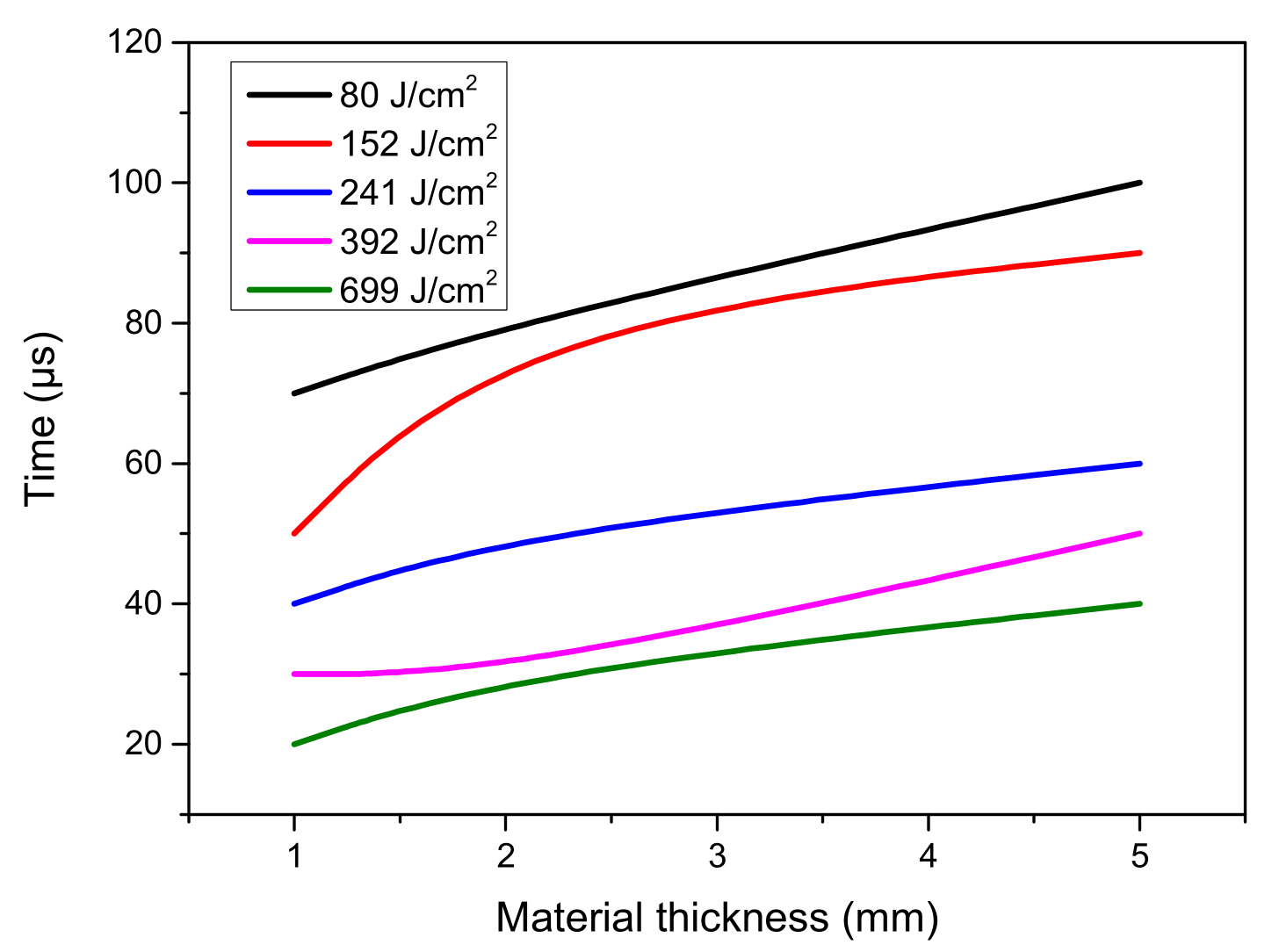
Figure 3 shows the relationship between the heating time and the energy density of CFRP materials with different thicknesses under the action of 1 ms pulse width laser. The materials of different thicknesses have similar trends with the laser energy density, but the thicker target material heats up more slowly. When the energy density is about 80 J/cm
2, the target thickness of 5 mm even needs 100 μs to heat up to 3500 °C, while the target thickness of 1 mm only needs 70 μs under the same laser conditions. This difference is determined by the thermal conductivity of the material. When the laser energy reaches the thicker material, the upper layer can better transfer the energy to the lower layer, and its thermal conductivity coefficient is much greater than that of air. The thin CFRP is more obstructed when transferring heat outward, so the heating time is shorter and the speed is faster.
The experimental results of CFRP surface temperature with time under different laser energy density are shown in the
Figure 4. It can be seen from the figure that under the condition of single pulse, when the laser energy density is different, the surface temperature of CFRP increases with the laser action time. Due to the high energy density of the laser, the surface temperature of the CFRP material rises rapidly, and the time to reach the vaporization point is only within a few microseconds. Since the strength and elastic modulus of carbon fiber materials remain basically unchanged at high temperatures above 2000 °C, it can be considered that the process of heating up is mostly fiber oxidation and resin decomposition. Carbon fiber will continue to absorb laser energy and then continue to heat up until it reaches the gasification point of 3500 °C. After the carbon fiber reaches the gasification point of 3500 °C, with the continuous injection of laser energy, the target surface temperature should continue to increase. However, since the upper limit of the thermometer is 3500 °C, the output temperature of the thermometer is always 3500 °C, which shows an isotherm in the
Figure 4.
When multiple pulses continuously act on the woven CFRP material, its surface temperature increases and decreases repeatedly with the laser pulse. Under the action of different energy densities, the temperature drop rate and fall value are different at the end of each pulse. The greater the energy density, the slower the temperature decline rate, and the fall temperature measured in the experiment shows that it has a significant temperature accumulation effect. In the experiment, five laser pulses were used to irradiate the CFRP target with a braided structure. The pulse width was 1 ms, the repetition frequency was 10 Hz, and the laser output energy was adjusted (152–699 J/cm2) to obtain the end of each pulse and the target at the time of the next pulse. The temperature of the surface is the initial temperature at which each pulse acts on the target starting from the second pulse.
As shown in
Figure 5, under the action of lasers with different energy densities, the temperature drop of the material after each pulse is different. After the end of the first pulse, under five different laser injection energies, there was no temperature accumulation higher than 350 °C. When the energy density is 392 J/cm
2 and 699 J/cm
2, after the end of the second pulse, the temperature will obviously accumulate when the third pulse arrives; when 241 J/cm
2 and 152 J/cm
2, they are in the third and fourth After the end of each pulse, the temperature drops back above the initial temperature. Under the action of a laser with a fixed pulse frequency, the higher the energy density, the more obvious the temperature accumulation is and the higher the fall temperature. When the laser energy density is constant, the fallback temperature increases as the number of pulses increases.
Figure 6 shows the differences between various samples. The morphology illustrated that elliptical surface structures although the laser beam spot is a circle. Similar to the results by simulation, the axis of the ellipse is precisely as the axis of the carbon fiber. From the top view, the elliptical performance is clearer, when the laser beam irradiates just right on the cross-section of fibers. Moreover, due to the braided structure, the position of the laser beam on these samples are all at the upper fibers. At the same time, all long axes of ellipses are corresponding to these upper fibers. The bottom row shows the right view of the samples’ morphology focusing on debris. It is clear that all sample appear debris at the top surface around the hole. The highlight is the variety of debris size in the horizontal and vertical axes. The debris is only gathered in the long axis of the ellipse and is less in the short axis, which is either due to the magnetizable effect or is related to the formed pattern of the carbon fiber.
Furthermore, the shape of the ablation hole under the surface is regular cone but not an elliptic cone. The elliptical phenomenon only appears on the material surface. When the prepreg material formed to a carbon fiber plate, the blank between the fibers in adjacent layers is filled by epoxy. However, the epoxy will be removed at the initial moment of laser processing, and the heat in z direction will hardly transfer into the next layer especially via the air.
In order to further analyze the anisotropy of heat conduction in CFRP, it can be discussed from a microscopic perspective. The heat transfer of metal material depends on the lattice thermal vibration wave and free electron flow. Therefore, the heat transfer of metal materials mainly depends on free electrons. However, the heat transfer of non-metallic materials mainly depends on lattice vibration, which does not follow the Weideman-Franz law. Carbon fiber belongs to this type of non-metallic materials. The atoms at a high temperature have a larger amplitude, and those at a low temperature have a smaller amplitude. The heat energy is transferred gradually from high to low in order to balance the temperature. Therefore, the phenomenon is attributable to the differences among the three directions of fibers.
Figure 7 is a schematic of the thermal vibrations of the lattice. The vibration of atoms in the lattice at a certain temperature has a corresponding amplitude (displacement). The atoms at a high temperature have a larger amplitude, and those at a low temperature have a smaller amplitude. The heat energy is transferred gradually from high to low in order to balance the temperature. Therefore, the phenomenon is attributable to the differences among the three directions of fibers.
Moreover, the property of CFRP composite is sensitive to particular laser condition. When the laser irradiates on carbon fibers, due to the organized oscillations of lattice vibration of material, the fiber would crack and burst apart in the horizontal direction. However, after interaction with resin, the laser is not still the original condition, so the elliptic is not formed in the next layer. Therefore, the shape of the ablation hole is still regular and not an elliptic cone (which differs from the top surface).
The morphology illustrated that elliptical surface structures (although the laser beam spot is a circle). Similar to the results by simulation, the axis of the ellipse is precisely as the axes of carbon fiber. From the top view, the elliptical performance is clearer when the laser beam irradiates right on the cross-section of fibers. Moreover, due to the braided structure, the position of the laser beam on these samples are all at the upper fibers. At the same time, all long axes of ellipses correspond to these upper fibers.
The bottom row shows the right view of the samples’ morphology focusing on debris. It is clear that in all samples, debris appears at the top surface around the hole. The highlight is the variety of debris size in horizontal and vertical. The debris only gathered in the long axis of the ellipse, and is less in short axis (which is due to the magnetizable effect or related to the formed pattern of carbon fiber).
Furthermore, the shape of the ablation hole under the surface is a regular cone, not an elliptic cone. The elliptical phenomenon only appears on the material surface. When the prepreg material forms to a carbon fiber plate, the blank between the fibers in adjacent layers is filled by epoxy. However, the epoxy will be removed at the initial moment of laser processing, and the heat in z direction will hardly transfer into the next layer (especially via the air).


