Article

Modeling and Evaluation of a Novel Hybrid-Driven Compliant Hand Exoskeleton Based on Human-Machine Coupling Model

1
Institute of Rehabilitation Engineering and Technology, University of Shanghai for Science and Technology, Shanghai 200093, China
2
Shanghai Engineering Research Center of Assistive Devices, Shanghai 200093, China
3
Key Laboratory of Neural-Functional Information and Rehabilitation Engineering of the Ministry of Civil Affairs, Shanghai 200093, China
4
College of Rehabilitation Sciences, Shanghai University of Medicine and Health Sciences, Shanghai 201318, China
*
Authors to whom correspondence should be addressed.
Appl. Sci. 2021, 11(22), 10825; https://doi.org/10.3390/app112210825
Submission received: 14 October 2021 / Revised: 11 November 2021 / Accepted: 15 November 2021 / Published: 16 November 2021
(This article belongs to the Special Issue Application of Compliant Mechanisms in Robotics)

Abstract

:
This paper presents the modeling design method for a novel hybrid-driven compliant hand exoskeleton based on the human-machine coupling model for the patients who have requirements on training and assisting. Firstly, the human-machine coupling model is established based on the kinematics characteristics of human fingers and the Bernoulli beam formula. On this basis, the variable stiffness flexible hinge (VSFH) is used to drive the finger extension and the cable-driven mechanism is used to implement the movement of the finger flexion. Here, a hand orthosis is designed in the proposed hand exoskeleton to act as the base and maintain the function position of the hand for patients with hand dysfunction. Then, a final design prototype is fabricated to evaluate the proposed modeling method. In the end, a series of experiments based on the prototype is proceeded to evaluate its capabilities on stretching force for extension, bio-imitability, finger flexion capability, and fingertip force. The results show that the prototype has a significant improvement in all aspects of the ability mentioned above, and has good bionics. The proposed design method can be utilized to implement the rapid design of the hybrid-driven compliant hand exoskeleton with the changed requirements. The novel modeling method can be easily applied in personalized design in rehabilitation engineering.

1. Introduction

Human hands are vital organs because they can help us perform the activities of daily living (ADL) every day. However, many people suffer hand dysfunction caused by accidents and diseases, especially central nervous system pathology, such as sequelae of stroke [1], traumatic brain injury [2], and spinal cord injury [3]. Hand rehabilitation training and assistance can sometimes restore their hand function to a normal level [4]. However, insufficient rehabilitation therapists and long recovery periods make it difficult to provide intense rehabilitation. To improve the efficiency of rehabilitation and relieve the workload of therapists, a series of effective hand exoskeletons have been verified and developed to offer rehabilitation training and assist ADL [5,6,7].
Recently soft materials have been widely used in hand exoskeletons due to their portability and good interactivity, which bring better comfort and convenience to wearers. Four main different actuation methods are widely used in compliant hand exoskeletons, including pneumatic actuation [8,9,10,11], tendon-driven actuation [12,13,14,15,16,17,18,19], elastomeric actuation [20,21,22], and hybrid-driven actuation [23,24,25].
In the design of pneumatic actuation, the composite [8,9] or segmented [11] structure of the air chamber enables the hand exoskeleton to achieve a predetermined bending motion. The air chamber fitted to the finger can produce uniform force to improve comfort, which has received lots of attention. However, the hand exoskeleton with pneumatic actuation has the disadvantages of the bulky system of air pump and complex structural design of air chamber, which limits the flexibility of use in ADL.
The portability and the large output force of the tendon-driven hand exoskeleton make it more suitable for ADL. For example, Kang et al. [17] designed a bidirectional tendon-driven hand exoskeleton that owns a compact soft glove of 104 g and can provide a maximum grasping force of 23 N. However, the bidirectional driven tendons require elaborate capstans of different sizes to achieve the coordinated control of flexion and extension.
The flexible hinges, such as sliding spring [20] or steel strap [21] are widely used in elastomeric actuation as the most necessary active driving components. The controllable deformation direction of the flexible hinge enhances the stability and safety of the hand exoskeleton. However, these hand exoskeletons need additional limiting mechanisms to assist the flexible hinge to achieve a specific bending motion. For flexible hinges used in the hand exoskeleton, there is still a lack of efficient theoretical design methods to improve the bending properties.
Hybrid-driven actuation can be combined in a variety of ways. Biggar et al. [23] suggested a hand exoskeleton, which first flexes under the drive of tendons and then utilizes an air pump to absorb objects to grasp like an octopus. Two different active drivers improve the grasping ability, but at the same time increase the cost and complexity of the device [23,24].
Among these considerations, a hybrid-driven hand exoskeleton with a combination of active tendon-driven actuation and passive flexible hinge has been presented [25] in our preliminary work. The active-passive hybrid-driven hand exoskeleton not only maintains the portability of the single active driver but also uses the flexible hinge to provide passive stretching force for efficient extension and a simple transmission mechanism. However, this hand exoskeleton has several shortcomings in practice:
  • Due to the remote placement of the motor, long tendons require additional protection and guidance of Teflon tubes and reduce the efficiency of force transmission.
  • For multi-degree of freedom (DOF) fingers, each joint needs a separate flexible hinge to provide stretching force, which not only increases the number of components but also is not conducive to the wearing of hand exoskeleton.
  • The flexible hinge designed independently of the human finger has uncoordinated interaction performance, so the hand exoskeleton hand is prone to produce uncertain extrusion and interference with the finger during the bending process.
This paper presents a novel hybrid-driven compliant hand exoskeleton based on the proximal placement of the motor and the end-traction of the flexible hinge to improve the aforementioned shortcomings. Most importantly, a human-machine coupling model of variable stiffness flexible hinge (VSFH) is established to predict the stretching force and improve bio-imitability. Then, the prototype of the hand exoskeleton is fabricated and its structure and properties are further analyzed and summarized. Finally, we conduct simulation and experiment on the improved VSFH to evaluate the effectiveness of the proposed modeling method. The finger flexion and fingertip force experiments are performed on a healthy subject, indicating a reasonable finger flexion angle and sufficient fingertip force to assist ADL.

2. Human-Machine Coupling Model

2.1. Principle

As shown in Figure 1, the basic design principle of the hand exoskeleton is inspired by the structure of the human hand. Since the exoskeleton attaches to the outside of the hand, the influence of phalange thickness and exoskeleton height should be considered in the design. The hand exoskeleton should provide both the flexion unit that simulates the finger flexion and the elongation unit caused by the distance from the center of the joint to the exoskeleton.
According to the basic design principle, the structure of the human hand determines the design parameters of the hand exoskeleton. Where L1, L2, and L3 are the lengths of proximal phalange (PP), intermediate phalange (IP), and distal phalange (DP), φ1, φ2, and φ3 are the joint angles of metacarpophalangeal (MCP), proximal interphalangeal (PIP), and distal interphalangeal (DIP), t is the thickness of phalange.
In the process of finger flexion, the required flexion compensation of each joint ΔLi is defined as follows:
Δ L i = ( h + t 2 ) φ i
where h is the distance from the exoskeleton to the dorsal finger.

2.2. Large Deflection Analysis of Cantilever Beam

The design of stiffness (change in thickness) and bio-imitability of flexible hinges is an important topic in this paper to meet the requirements of stretching force and avoid interference between the hinge and finger. Su [26] determined the large deflection of a single cantilever beam through an established pseudo-rigid-body (PRB) 3R model. However, to realize the bio-imitability of the flexible hinge, the cantilever beams with different stiffness should be connected in series into the VSFH, so that each segment can realize synchronous flexion with the corresponding finger joints. For multi-hinge, the PRB model will produce too many characteristic radius factors, which aggravates the analysis of the model, so that the classical Bernoulli beam formula is more convenient and effective to establish the model of the VSFH [27].
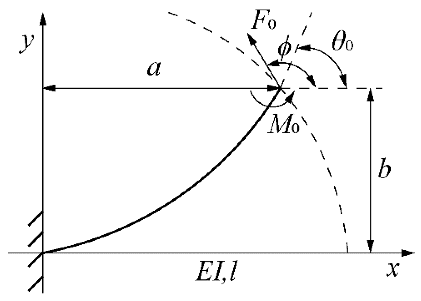
As the basic flexion unit, the model of a single flexible hinge shows in Figure 2. One end of the initially straight cantilever beam is fixed and the other end is subjected to a combined force F0 and moment M0. The tip slope angle and the direction of the end force are θ0 and ϕ. Parameters a and b are the horizontal and vertical tip deflections.
Refer to (2) and (3), which are the curvature of a beam in cartesian coordinates and Bernoulli–Euler, respectively, the curvature of cantilever beam k can be calculated by
k = 1 ρ = d θ d s = d 2 y / d x 2 [ 1 + ( d y / d x ) 2 ] 1 / 2
M E I = d θ d s
k = 2 F 0 E I [ cos ( ϕ θ 0 ) cos ( ϕ θ ) ] + ( M 0 E I ) 2
where E and I are the Young’s modulus and the inertia moment, respectively.
By applying the chain rule and the coupling to (2), the length of the hinge l and the deflections of the tip can be obtained by
l = 0 θ 0 d θ k
a = 0 θ 0 cos θ k d θ
b = 0 θ 0 sin θ k d θ

2.3. Large Deflection Analysis of VSFH

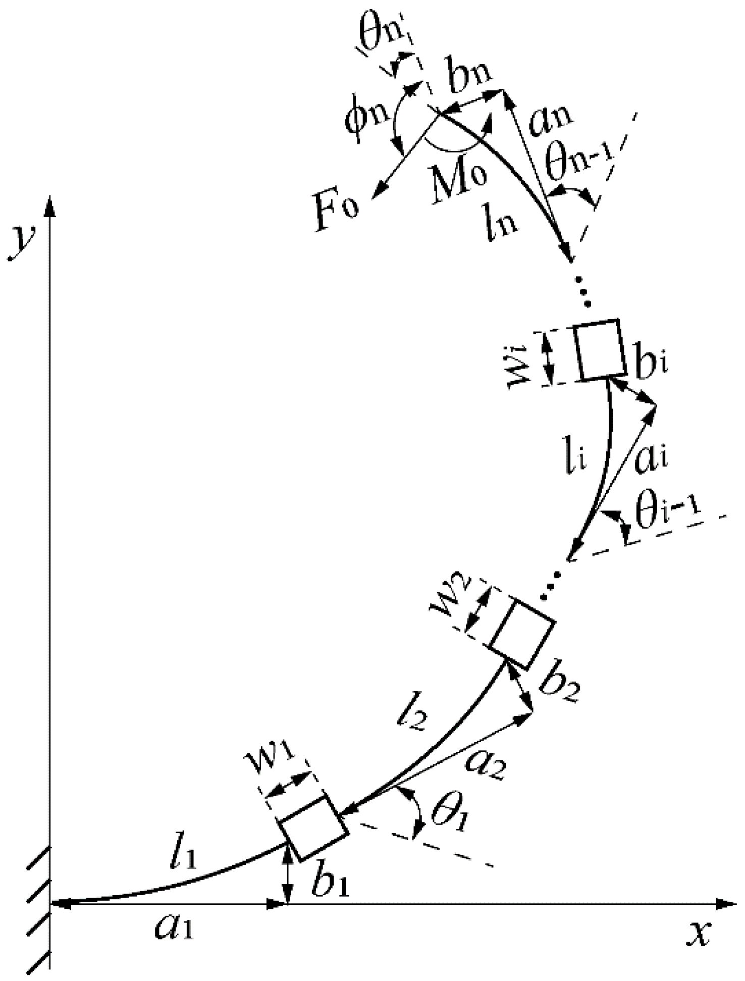
Figure 3 shows a VSFH subjected to a combined end force and moment. The model is composed of n hinges with different stiffness connected by n − 1 rigid connecting blocks. The hinge with force and moment, in the end, is the n-th hinge. The length of the rigid connecting block along the direction θi is denoted by wi (wi ≥ 0).
The moment at the end of the i-th hinge (I ≤ n − 1) can be calculated by the deflection of VSFH as follows:
M i = x = i + 1 n { F 0 [ ( a x + w x 1 ) sin ϕ x b x cos ϕ x ] } + M 0
Plugging (8) into (4) and rearranging terms, the curvature of the corresponding hinge can be calculated by
k i = 2 F 0 E i I i [ cos ( ϕ i θ i ) cos ( ϕ i θ ) ] + ( M i E i I i ) 2
The curvature of the n-th hinge can be calculated according to (4).
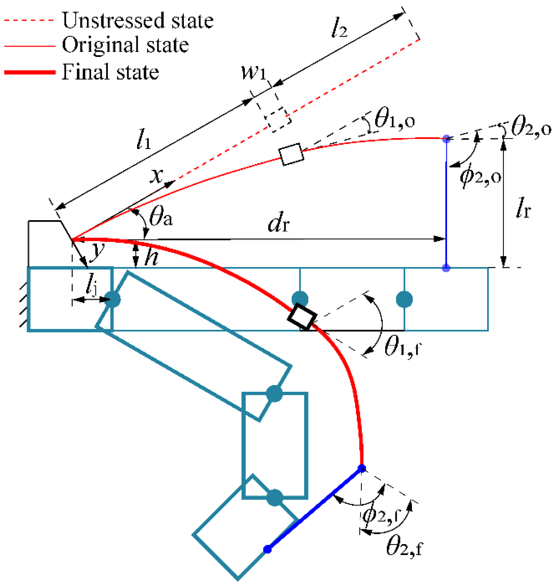
This section presents a simplified human-machine coupling model of a single finger and VSFH in three different flexion states (see Figure 4). The established model can improve the flexion synchronization between VSFH and finger, to avoid interference by optimizing the stiffness relationship between each hinge in VSFH. Meanwhile, the human-machine coupling model is used to accurately calculate the stiffness of each hinge to provide personalized passive stretching force for wearers. Since the width difference of human fingers is small, the hinge width bh = 7 mm, and the thickness of the hinge is changed to obtain different stiffness. The length of the connection rope that connects VSFH to finger lr is used to compensate ΔL and optimize the assembly of VSFH.
In the model, VSFH is composed of two hinges with different stiffness. Here, we choose the length of connecting block w1 = 0 to improve the working life of the flexible hinge. The 1-th and 2-th hinges mimic the flexion and extension of MCP and PIP joints, respectively. The x-axis is aligned to the direction of the VSFH in the unstressed state and the center of the coordinate is placed at the fixed end of VSFH.
In the unstressed state, VSFH which is treated as a straight cantilever beam is assembled at angle θa (the angle between the VSFH and the horizontal line) on the fixed block of the dorsal palm. According to the measurement of finger phalanges, the required lengths of each hinge is defined as follows:
l 1 = l j + L 1
l 2 = L 2 + L 3
where lj is the horizontal distance from the fixed end of VSFH to the center of MCP joint.
In the final state, the flexion angles of each joint and hinge reach the maximum. Furthermore, the flexion angles of each hinge correspond to that of finger joints, so that VSFH and finger can be flexed in equal proportion to achieve synchronous motion. The final flexion angles of both hinges in the human-machine coupling model are defined as follows:
θ 1 , f = θ a + φ 1
θ 2 , f = φ 2
where θ1,f and θ2,f are the final flexion angles of the 1-th hinge and the 2-th hinge.
In the original state, we assume that the finger is straight under the action of the stretching force generated by the deformation of VSFH, so that φ1 = φ2 = φ3 = 0. Meanwhile, the connection rope connects the free end of VSFH perpendicular to the finger. According to the assembly angle θa, the original flexion angles of both hinges in the human-machine coupling model are defined as follows:
θ 1 , 0 = θ 1 , f θ a θ 1 , f + θ 2 , f
θ 2 , 0 = θ 2 , f θ a θ 1 , f + θ 1 , f
where θ1,0 and θ2,0 are the original flexion angles of the 1-th hinge and the 2-th hinge. Because the whole flexion angle of VSFH is equal to the assembly angle in the original state, the free end of VSFH is parallel to the direction of finger.
Since VSFH cannot compensate for the elongation caused by the flexion of the joints, the length of the connection rope that is determined by the vertical distance from the free end of VSFH to the dorsal finger in the original state is crucial. In the coordinate system established in the model, the coordinates of the free end of VSFH (x2,0, y2,0) are defined as follows:
[ x 2 , 0 y 2 , 0 0 ] = [ cos θ 1 , 0 sin θ 1 , 0 a 1 , 0 sin θ 1 , 0 cos θ 1 , 0 b 1 , 0 0 0 0 ] [ a 2 , 0 b 2 , 0 1 ]
According to the position of this point (x2,0, y2,0), the length of the connection rope lr and the horizontal distance between the connection rope and the fixed end of VSFH dr in the original state are defined as follows:
l r = x 2 , 0 tan θ a y 2 , 0 tan 2 θ 0 + 1 + h
d r = x 2 , 0 2 + y 2 , 0 2 ( l r h ) 2
Based on the human-machine coupling model, in addition to optimizing the stiffness relationship between each hinge in VSFH, two additional conditionals should be met to improve the interactive performance between the hand exoskeleton and finger. Condition 1 is that lr should be longer than ΔL to avoid squeezing caused by inadequate compensation.
Condition   1 :   l r i = 1 3 Δ L i
Condition 2 is that the connection point between the connection rope and the finger should be on the distal interphalangeal (DP) to provide stretching force for each joint and big moment arm.
Condition   2 :   l j + L 1 + L 2 d r l j + L 1 + L 2 + L 3
MATLAB is needed to solve the integrated model to calculate the theoretical value of the assembly angle and the thickness of each hinge. In the process of solving the model, the lengths of each hinge are firstly decided through the (10) and (11). The assembly angle can be empirically set to a range of values and the original flexion angle of each hinge can be known through (12)–(15). The stretching force is set as an independent variable and the thicknesses needed for each hinge to reach the same angle under different forces are calculated through (5)–(9) to understand the relationship between the deformation of VSFH and stretching force. Finally, the position of free end of VSFH can be obtained through (16)–(18).
The material of VSFH is polylactic acid (E = 2119 MPa). The cross-section of each hinge is rectangular so that I can be obtained by calculating the moment of inertia of the rectangular section. G. I. Bain et al. [28] measured the functional range of motion (ROM) of the finger joints, which is 19°–71°, 23°–87°, and 10°–64° at MCP, PIP, and DIP joints, respectively. Meanwhile, Kazeminasab et al. [24] proposed a hand exoskeleton that can provide passive stretching force through the linear spring, and the proportions of flexion angles are approximately 1:2:1.5 for the MCP, PIP, and DIP joints, respectively. Therefore, our expected joint angle of each joint and the size of the index finger of a healthy subject are listed in Table 1.
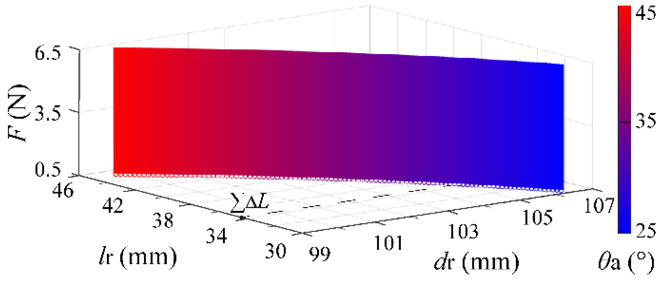
Through the MATLAB solution, Figure 5 shows the position of the free end of VSFH under the action of different assembly angles and stretching forces. As the assembly angle increases, the length of the connection rope increases, resulting in the free end of VSFH being further from the fingertip. The selected θa is 35°. The corresponding lr and dr are 38.4 mm and 103.4 mm, which meet conditions 1 and condition 2.
In Figure 5, the surface in a three-dimensional coordinate system is projected onto an x-y coordinate system as a curve rather than a plane field, which indicates that when hinges with different stiffness flex to the same angle under the corresponding force, the free end of VSFH will reach the same position. Therefore, in the process of use, lr and dr are constant even if the patient needs different stretching forces to change the thickness of VSFH.
Through the application of curve fitting in MATLAB, the relationship between the thicknesses of each hinge and the required stretching force are defined as follows.
h 2 = 0.0003706 F 5 0.007841 F 4 + 0.0661 F 3 0.293 F 2 + 0.8935 F + 0.7444
h 1 = 0.0006093 F 5 0.01289 F 4 + 0.1086 F 3 0.4815 F 2 + 1.469 F + 1.224
h 1 = 1.644 h 2
Refer to (23), there is a linear relationship between the thickness (stiffness) of each hinge when there is a proportional relation between the flexion angle of each hinge in series.

3. Design and Prototype

3.1. Design and Prototype Implementation

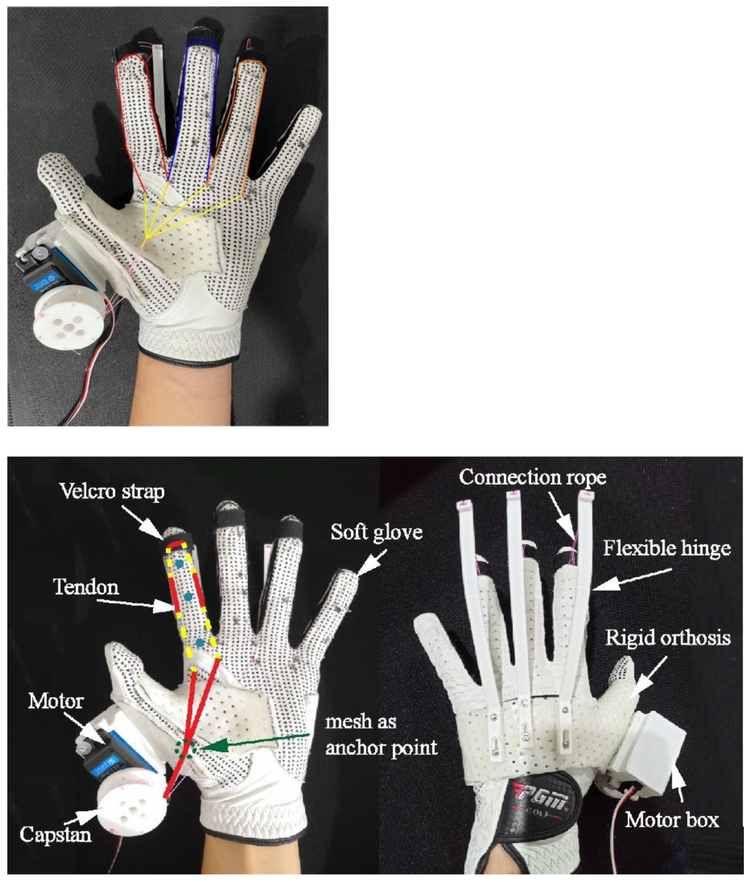
In this section, the main components of the proposed novel hybrid-driven compliant hand exoskeleton are presented in Figure 6.
The rigid orthosis used to support the palm and thumb is made of low-temperature thermoplastics, which can be customized quickly according to the hand size. A large number of meshes improve the air permeability of the orthosis and the half-wrapped design of the volar body makes it more versatile and comfortable to wear.
One end of the flexible hinge is fixed to the orthosis, and the other end is attached to the fingertip with a connection rope and Velcro strap to extend the finger. Because of similar length, the index, middle, and ring fingers are equipped with same-sized flexible hinges, which are 3D printed to facilitate the individual design (Raise3D Pro2 Plus, China, printing accuracy = 0.01 mm).
The soft glove is a commercially available common baseball glove, which is low-cost and practical. The strap of the wrist is made of less elastic artificial leather for good fixation, and the volar body of the glove is made of elastic fabric material, which is suitable for different sizes of hands to provide better wrapping. In the volar body, the tendons made of fishing line with low friction and the soft glove are sewn together to form a unidirectional under-actuation mechanism.
In Figure 6, left, the marking lines and circles on the index finger are the path of tendons arrangement and finger joints, respectively. The dotted and solid lines indicate that the tendons are located on the inside and outside of the glove, respectively. The crossing points of the dotted and solid lines treated as anchors are at the upper part of the phalange for greater torque [18]. The tendons are arranged symmetrically on both sides of the finger rather than on the palmar surface, which can alleviate the condition of tendons in direct contact with objects caused by glove deformation to improve the sense of touch. Similar to the flexible hinges, the tendons are also attached to three fingers except the little finger, which allows three fingers of similar length to move synchronously through a single capstan, thus simplifying control. In addition, since the deformation of the soft glove has a significant impact on the actual tendon stroke used for finger flexion [19], and empirically designed capstan provides enough stroke to flex fingers.
A large torque motor (Steering gear, DS3218 mg, China) mounted in the motor box is fixed to the orthosis to actuate the multiple tendons with ease.

3.2. Properties

This section further describes the properties of the hand exoskeleton and the design details of the corresponding structure.

3.2.1. Stability

In the hand exoskeleton, rigid orthosis plays a vital role in stability. Firstly, the rigid orthosis fixes the palm to prevent hand contracture in patients with spasms. Secondly, when grasping, the thumb mainly provides opposite support from the other fingers, so that the joints of the thumb especially the carpometacarpal joint need to be stable. Through the orthosis, the thumb is fixed in the functional position, which can not only provide stable support but also be convenient to grasp. Thirdly, instead of rigid support embedded in the soft glove, the orthosis acts as a separate rigid base, not only to fix the flexible hinges and the motor but also to prevent deformation of the soft glove. Meanwhile, the large stressed area disperses the support force to the whole palm, thus avoiding the stress concentration and improving the comfort of wearing.

3.2.2. Extension Capability

The stretching force provided by the flexible hinge at the fingertip is perpendicular to the finger, indicating that the moment arm is large enough to generate adequate extension torque for the finger joints, thus improving the conversion efficiency between tension and torque required for finger joints extension.

3.2.3. Human-Machine Interactive

The end-traction of the flexible hinge does not limit the abduction and adduction of the MCP joint coupled to the flexion and extension of the finger, to facilitate grasp. In addition, the bionic large deformation of VSFH can follow the finger in a synchronous flexion under the drive of the tendon and extend the finger with energy storage, which can avoid interference between hand exoskeleton and human hand.

3.2.4. Grasp Capability

In addition to the usage of a large torque steering motor and the arrangement of tendons on the fingers, the effective transmission of tendon tension enhances the ability to grasp simultaneously. Firstly, the proximal placement of the motor reduces the length of tendons, thus avoiding excessive energy loss because of friction of tendons in long-distance transmission. Secondly, the tendons from the fingers to the capstan pass through the meshes that serve as anchor points on the rigid orthosis (see Figure 6) rather than a soft glove, which reduces the deformation of the glove and improves the transmission efficiency of tendon-driven hand exoskeleton [19]. Thirdly, the groove of the capstan connected with the tendon is in the same plane as the volar surface, which reduces the generation of the inflection point of tendons and further improves the efficiency of force transmission.

3.2.5. Portability

In ADL, there is no burden on patients when the hand exoskeleton weighs less than 400 g [13]. By using 3D printed technology, lightweight materials, and a single motor, the total weight of the wearable part including the motor is 147 g, which is portable for wearers to use at home, not just in the clinic.

4. Evaluation

4.1. Stretching Force

An experiment is designed to measure the stretching force of VSFH to quantitatively demonstrate that VSFH can provide precious stretching force for stroke patients and the validity of the relationship between hinge thickness and force in the simulation model. Referring to the finger stiffness of stroke patients with spasm [29], the MCP joint of the index finger requires extension torque of 0.46 Nm so that VSFH needs to provide a 5.51 N stretching force.
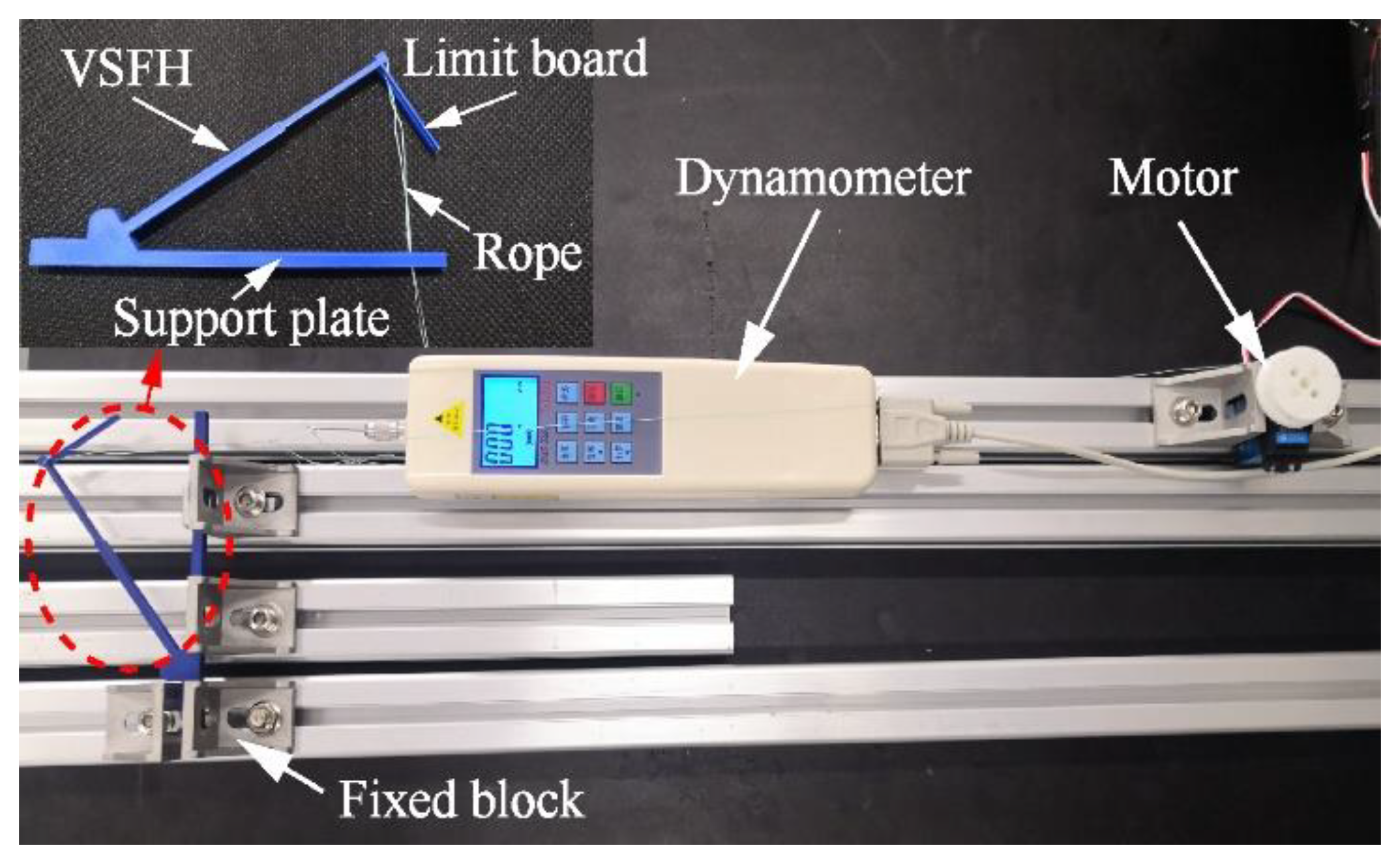
The experiment setup is on a stationary platform that provided the slide track. The motor and VSFH for the test are fixed on the platform by a fixed block. The body and the force end of the dynamometer are connected to the motor and the free end of VSFH by ropes, respectively. In addition, the VSFH for the test includes a support plate for fixation, a VSFH 3D printed according to (21) and (22) and Table 1 (h1, h2 >> printing accuracy), and a limit board used to simulate the connecting rope. In all experiments where the motor is used, the working parameters of the motor are the same, including 10 s forward rotation time and 10 s reversal time in one cycle, the corresponding maximum rotation angle is 270°, and the diameter of the capstan is 25 mm. Figure 7 shows the experimental setup.
The limit board at the free end of VSFH imitates the function of the connection rope in its original state by providing a limit so that the length of the limit board is lr and the maximum flexion angle of VSFH is θa. In the process of measurement, the motor pulls the dynamometer at a constant speed to bend VSFH with or without the limit board. The stretching forces provided by VSFH are recorded in real-time and compared. In addition, in the measurement experiment with the limit board, the motor is reversed in advance artificially to protect the limit board. Figure 8 shows the results of the experiment.
Results with limit board show that the stretching force changed abruptly at a certain point in time, indicating that the limit board touches the support plate used to imitate a human finger at this time and the value of abrupt point is the magnitude of the original stretching force. Results without limit board show the variation of the stretching force during a complete driving cycle, which indicates that we can change the material of the hinge to reduce the rate of change in stretching force, thus further improving the stability of hinge flexion.
Compared to the required stretching force for stroke patients, the actual stretching force can provide 5.70 N with an error of 3.4%, indicating that the simulation model is correct. The corresponding VSFH can be designed to provide different precise stretching forces and resistance according to the needs of patients.

4.2. Bio-Imitability

The expected flexion angle ratio of the 2-th and 1-th hinges in VSFH is θ2,f/θ1,f. To check the bio-imitability of improved VSFH, the thickness of the constant stiffness flexible hinge (CSFH) is calculated at the same assembly angle and total original flexion angle as VSFH and obtained by MATLAB as follows:
h 2 = h 1 = 0.0005376 F 5 0.01136 F 4 + 0.09556 F 3 0.4217 F 2 + 1.276 F + 1.049
where h 1 and h 2 are the thicknesses of the 1-th and 2-th hinges in CSFH, respectively.
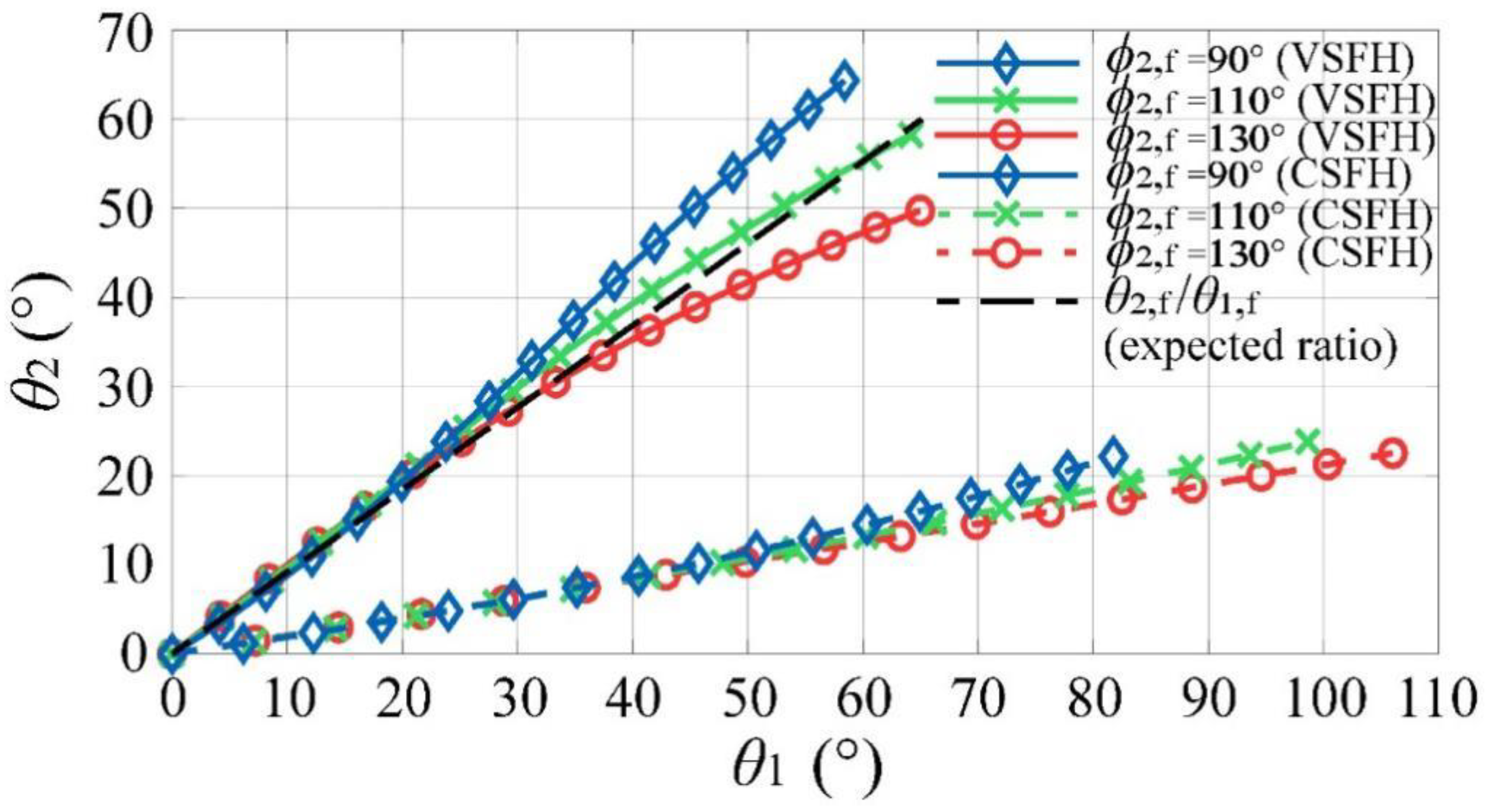
Taking the stretching force of 1 N as an example, the thicknesses of each hinge are calculated and substituted back into the coupling model. During finger flexion, the direction of the force exerted by the connection rope on the flexible hinge changes in real-time. Therefore, some setup adjustments are needed to the model used for verification. The flexion angle of each hinge in VSFH and CSFH are simulated under three different directions of the force ϕ2,f, and the same maximum force F0, max. As shown in Figure 9, the respective flexion angles of the 2-th and 1-th hinges increase with increasing F0.
Assuming that the flexion angle ratio is linear in Figure 10, we compare the coefficients of the fitting curves with the expected flexion angle ratio in each case and find that the bio-imitability of VSFH is on average 60.3% better than that of the CSFH. According to the conclusion in Figure 5, VSFH with other stiffness can also flex to the same angle to achieve synchronous movement. The improved VSFH can avoid the excessive flexion of CSFH at MCP joint, so as not to cause interference with a finger.

4.3. Finger Flexion

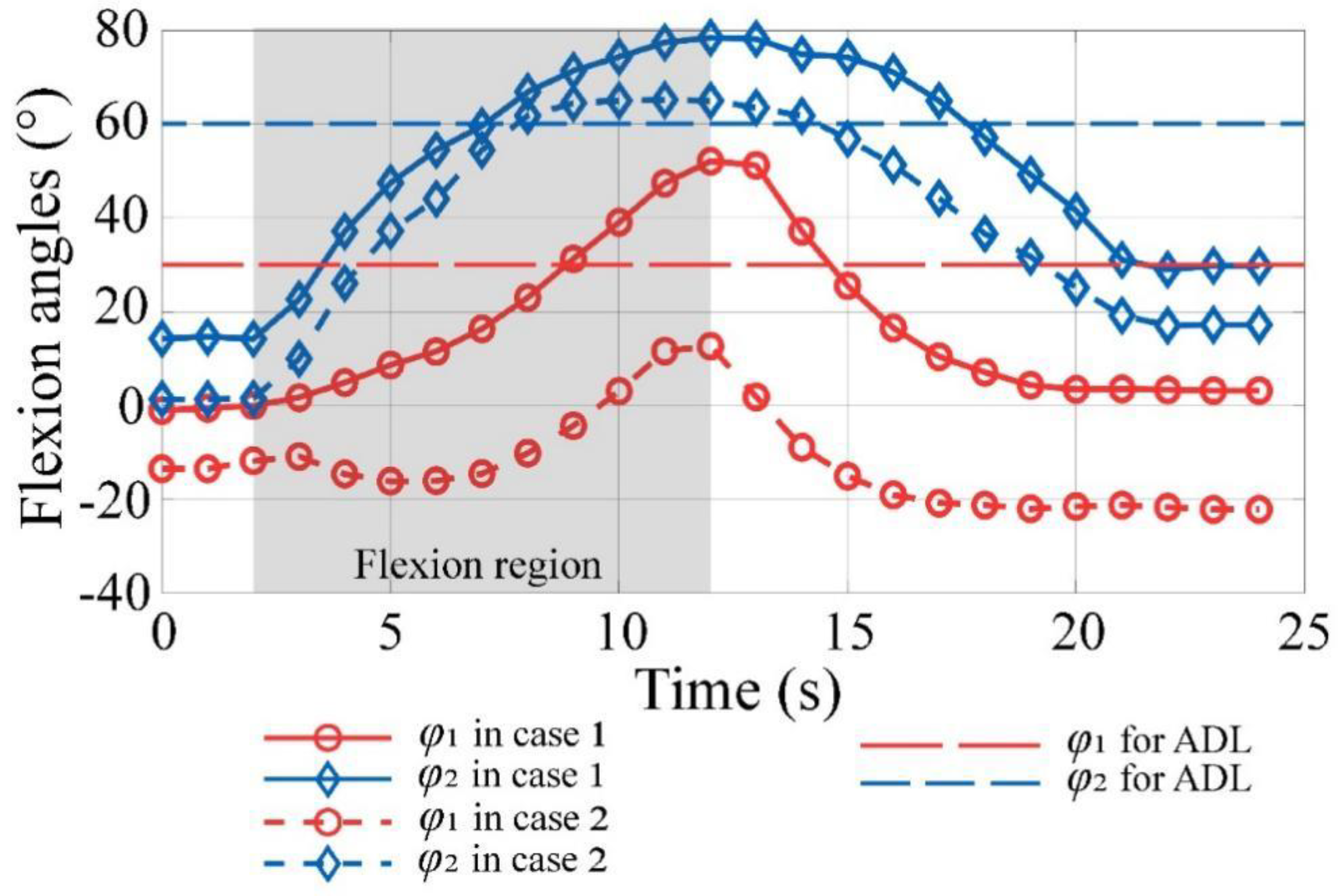
The experiment setup is used to evaluate the function ROM of the finger for assistance. The flexion angles of MCP and PIP joints should be greater than the expected 30° and 60°, respectively.
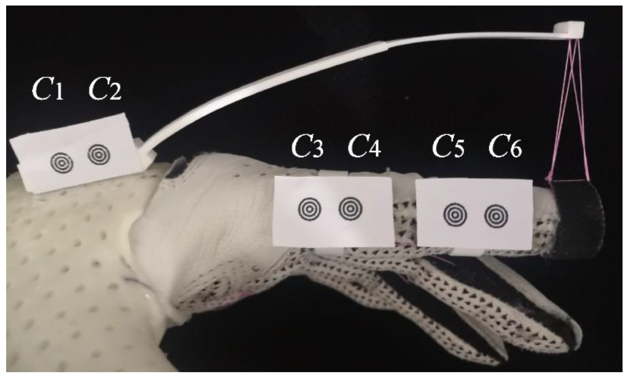
As shown in Figure 10, The index finger motion can be captured with a camera. The six rippled markers Ci (xi, yi) are mounted on the fixed end of VSFH and the side of PP and IP, numbered 1–6, starting with 1 from left to right. Furthermore, the central coordinates of the markers can be extracted by image processing based on dilation and erosion of MATLAB. Firstly, the slopes of the dorsal palm, PP, and IP are obtained by Ci, and then the flexion angles of MCP and PIP joints can be calculated based on these slopes. To facilitate the differentiation of different motion states, the motor started working after the camera takes 2 s. The subject is a healthy person with normal hand function who is asked not to apply any active force to mimic muscle weakness. In addition, due to the original assembly deviation of the markers (the MCP joint has an original angle because of the non-horizontal state of C1, C2 in Figure 10), the palm will be placed on a horizontal table to measure the original angle of each joint before the experiments, so the deviation can be eliminated from the experimental results.
To provide a reasonable reference for the required passive stretching force of end traction hand exoskeleton in ADL, this evaluation is conducted on two cases.
Case 1: the VSFH which is designed with 47.75 × 10⁻³ Nm torque required to extend the MCP joint horizontally in normal subjects [30] is assembled to provide passive stretching force. In practice, the length of the connection rope is increased by 10 mm to provide a more suitable stretching force, so that the original angle of the MCP joint can be close to 0°. Therefore, in addition to the reference value for universality, a dynamometer that simulates the connecting rope in its original state can be used to measure the actual stretching force of wearers to design VSFH. We can appropriately change lr to achieve a small adjustment of the stretching force.
Case 2: the VSFH which is designed with 59.13 × 10⁻³ Nm torque required to extend the PIP joint horizontally in normal subjects [31] is assembled to provide passive stretching force. Figure 11 shows the results of these two cases.
For case 1, the MCP joint extends to −1° successfully, but the PIP joint has an original flexion angle of 14° because of insufficient torque at PIP joint. When flexion, the maximum flexion angles of MCP and PIP joints are measured at 52° and 79°, respectively. The flexion angles of both joints not only meet the expected values but also are similar to 3:5, which is the general flexion angle ratio of the MCP joint to the PIP joint of the normal hand [32]. For case 2, the PIP joint extends to 1°, and the MCP joint has a hyperextension angle of −14° due to excessive moment arm. When flexion, the maximum flexion angles of MCP and PIP joints are measured at 13° and 65°, respectively, which only meet the expected value at MCP joint.
For a hand exoskeleton that provides passive extension, the passive stretching force should be designed with the torque required for MCP joint, not only providing sufficient extension but also having a good flexion angle ratio. In Figure 11, the maximum flexion angle of each joint varies with the passive stretching force, so that we can refer to the results in case 1 to further improve the predetermined joint angels in Table 1.

4.4. Fingertip Force

In ADL, most functional tasks require less than 10.5 N pinch forces [33]. The total fingertip force provided by the motor determines whether the hand exoskeleton can assist the wearer in normal grasping.
In fact, for a compliant hand exoskeleton with a glove, the placement of force sensors is always a challenge [24]. A force-sensing resistor (FSR, RX-D1016, Rouxi Tech. Co., Bengbu, Shandong, China) is placed on the surface of the cylinder so that the motor only needs to drive the index finger to conveniently obtain the total fingertip force. The healthy subject is assigned to grasp objects with or without VSFH to explore the difference between the output force of the hand exoskeleton with VSFH and that of the general tendon-driven hand exoskeleton without passive stretching force. Meanwhile, the subject is instructed to grasp two cylindrical objects with diameters of 68 mm [see Figure 12a] and 50 mm [see Figure 13a] to measure the fingertip forces at different flexion angles. In all fingertip force experiments, the VSFH is designed based on the torque required for the MCP joint. The results are shown in Figure 12b and Figure 13b.
In Figure 12b, the maximum fingertip force lasted for 0.5 s, indicating that the motor output reaches the maximum power and is reversed in advance. With or without VSFH, the maximum index fingertip forces are 35.5 N and 36.1 N, respectively, indicating that the hand exoskeleton can provide the wearer with enough pinch forces to perform simple ADL. In Figure 13b, with or without VSFH, the maximum index fingertip forces are 14.7 N and 16.8 N, respectively, which also meet the requirement of ADL. There are some significant differences when grasping cylinders with different diameters. Firstly, the reason for the smaller fingertip force peak when grasping an object with a diameter of 50 mm is that the steering gear reaches the maximum rotation angle. Secondly, the difference in peak value produced by grasping the same object with or without VSFH is mainly due to the passive stretching force provided by VSFH, and this difference tends to increase as object diameter decreases.

5. Conclusions

This paper proposes a human-machine coupling model based on the motion feature of the human hand and the stiffness characteristic of VSFH for hand exoskeleton design. Based on the human-machine coupling model, a novel hybrid-driven compliant hand exoskeleton is also proposed in this work. For most patients with hand dysfunctions, the motion performance of hand exoskeletons should satisfy the individual myodynamia and the ROM of each joint. In addition, precision force control is the key problem to the existing hand exoskeleton because of the individual variation as mentioned before. The improved VSFH used in the proposed hand exoskeleton can provide precise stretching force for stroke patients with an error of 3.4% (experiment) and its bio-imitability is 60.3% higher than that of CSFH (simulation), which indicates that the human-machine coupling model can be used as a customized design method in the research of compliant hand exoskeleton. Meanwhile, this paper analyzed the motion and function characteristics of the MCP joint and PIP joint for the proposed hand exoskeleton designed based on the required torques of the MCP joint. The test experiment results show that it can assist the MCP and PIP joints of the finger to extend to −1° and 14°, and to flex to 52° and 79°, respectively. Furthermore, the maximum index fingertip force is 35.5 N and the weight of the exoskeleton from the hand is 147 g by a series of function tests. These performances verify that the novel hand exoskeleton is flexible, powerful, and portable for the wearer to carry out rehabilitation training and assistance.

Author Contributions

Conceptualization, Q.M. (Qiaoling Meng) and H.Y.; methodology, Q.M. (Qiaoling Meng) and Z.S.; software, Z.S. and Z.N.; validation, Z.S., Z.W. and Q.M. (Qingyun Meng); formal analysis, Z.S.; writing—original draft preparation, Q.M. (Qiaoling Meng) and Z.S.; writing—review and editing, Q.M. (Qiaoling Meng); visualization, Q.M. (Qiaoling Meng); supervision, H.Y.; project administration, H.Y. and Q.M. (Qiaoling Meng); funding acquisition, Q.M. (Qiaoling Meng). All authors have read and agreed to the published version of the manuscript.

Funding

This research was funded by the National Natural Science Foundation of China, grant number 61803265, and the Shanghai Municipal Commission of Science and Technology of China, grant number 20S31905400.

Institutional Review Board Statement

The study was conducted according to the guidelines of the Declaration of Helsinki, and approved by the Institutional Review Board (or Ethics Committee) of Shanghai University of Medicine and Health Sciences (protocol code 2019-ZYXM-04--420300197109053525 and 1 July 2019).

Informed Consent Statement

Informed consent was obtained from all subjects involved in the study.

Data Availability Statement

The data presented in this study are available on request from the corresponding author. The data are not publicly available as the data also forms part of an ongoing study.

Conflicts of Interest

The authors declare no conflict of interest.

References

  1. Takahashi, C.D.; Der-Yeghiaian, L.; Le, V.; Motiwala, R.R.; Cramer, S.C. Robot-based hand motor therapy after stroke. Brain 2007, 131, 425–437. [Google Scholar] [CrossRef]
  2. Roozenbeek, B.; Maas, A.I.R.; Menon, D.K. Changing patterns in the epidemiology of traumatic brain injury. Nat. Rev. Neurol. 2013, 9, 231–236. [Google Scholar] [CrossRef]
  3. Snoek, G.J.; Ijzerman, M.J.; Hermens, H.J.; Maxwell, D.; Biering-Sørensen, F. Survey of the needs of patients with spinal cord injury: Impact and priority for improvement in hand function in tetraplegics. Spinal Cord 2004, 42, 526–532. [Google Scholar] [CrossRef] [PubMed]
  4. Vanoglio, F.; Bernocchi, P.; Mulè, C.; Garofali, F.; Mora, C.; Taveggia, G.; Scalvini, S.; Luisa, A. Feasibility and efficacy of a robotic device for hand rehabilitation in hemiplegic stroke patients: A randomized pilot controlled study. Clin. Rehabil. 2016, 31, 351–360. [Google Scholar] [CrossRef] [PubMed]
  5. Proulx, E.C.; Beaulac, M.; David, M.; Deguire, C.; Haché, C.; Klug, F.; Kupnik, M.; Higgins, J.; Gagnon, D.H. Review of the effects of soft robotic gloves for activity-based rehabilitation in individuals with reduced hand function and manual dexterity following a neurological event. J. Rehabil. Assist. Technol. Eng. 2020, 7, 2055668320918130. [Google Scholar] [CrossRef] [PubMed]
  6. Palmcrantz, S.; Plantin, J.; Borg, J. Factors affecting the usability of an assistive soft robotic glove after stroke or multiple sclerosis. J. Rehabil. Med. 2020, 52, jrm00027. [Google Scholar] [CrossRef] [Green Version]
  7. Chu, C.-Y.; Patterson, R.M. Soft robotic devices for hand rehabilitation and assistance: A narrative review. J. Neuroeng. Rehabil. 2018, 15, 1–14. [Google Scholar] [CrossRef] [Green Version]
  8. Heung, H.L.; Tang, Z.Q.; Shi, X.Q.; Tong, K.Y.; Li, Z. Soft Rehabilitation Actuator With Integrated Post-stroke Finger Spasticity Evaluation. Front. Bioeng. Biotechnol. 2020, 8, 111. [Google Scholar] [CrossRef] [Green Version]
  9. Haghshenas-Jaryani, M.; Patterson, R.M.; Bugnariu, N.; Wijesundara, M.B. A pilot study on the design and validation of a hybrid exoskeleton robotic device for hand rehabilitation. J. Hand Ther. 2020, 33, 198–208. [Google Scholar] [CrossRef]
  10. Ge, L.; Chen, F.; Wang, D.; Zhang, Y.; Han, D.; Wang, T.; Gu, G. Design, Modeling, and Evaluation of Fabric-Based Pneumatic Actuators for Soft Wearable Assistive Gloves. Soft Robot. 2020, 7, 583–596. [Google Scholar] [CrossRef]
  11. Wang, J.; Fei, Y.; Pang, W. Design, Modeling, and Testing of a Soft Pneumatic Glove with Segmented PneuNets Bending Actuators. IEEE/ASME Trans. Mechatron. 2019, 24, 990–1001. [Google Scholar] [CrossRef]
  12. Park, J.; Heo, P.; Kim, J.; Na, Y. Qualitative Stability Analysis of Soft Hand Exoskeleton Based on Tendon-driven Mechanism. Int. J. Precis. Eng. Manuf. 2020, 21, 2095–2104. [Google Scholar] [CrossRef]
  13. Yurkewich, A.; Kozak, I.J.; Hebert, D.; Wang, R.H.; Mihailidis, A. Hand Extension Robot Orthosis (HERO) Grip Glove: Enabling independence amongst persons with severe hand impairments after stroke. J. Neuroeng. Rehabil. 2020, 17, 1–17. [Google Scholar] [CrossRef] [PubMed] [Green Version]
  14. Tran, P.; Jeong, S.; Wolf, S.L.; Desai, J.P. Patient-Specific, Voice-Controlled, Robotic FLEXotendon Glove-II System for Spinal Cord Injury. IEEE Robot. Autom. Lett. 2020, 5, 898–905. [Google Scholar] [CrossRef]
  15. Yoo, H.-J.; Lee, S.; Kim, J.; Park, C.; Lee, B. Development of 3D-printed myoelectric hand orthosis for patients with spinal cord injury. J. Neuroeng. Rehabil. 2019, 16, 1–14. [Google Scholar] [CrossRef] [PubMed] [Green Version]
  16. Rose, C.G.; O’Malley, M.K. Hybrid Rigid-Soft Hand Exoskeleton to Assist Functional Dexterity. IEEE Robot. Autom. Lett. 2018, 4, 73–80. [Google Scholar] [CrossRef]
  17. Kang, B.B.; Choi, H.; Lee, H.; Cho, K.J. Exo-Glove Poly II: A polymer-based soft wearable robot for the hand with a ten-don-driven actuation system. Soft Robot. 2019, 6, 214–227. [Google Scholar] [CrossRef]
  18. Gerez, L.; Chen, J.; Liarokapis, M. On the Development of Adaptive, Tendon-Driven, Wearable Exo-Gloves for Grasping Capabilities Enhancement. IEEE Robot. Autom. Lett. 2019, 4, 422–429. [Google Scholar] [CrossRef]
  19. Popov, D.; Gaponov, I.; Ryu, J.-H. Portable Exoskeleton Glove with Soft Structure for Hand Assistance in Activities of Daily Living. IEEE/ASME Trans. Mechatron. 2016, 22, 865–875. [Google Scholar] [CrossRef]
  20. Bützer, T.; Lambercy, O.; Arata, J.; Gassert, R. Fully Wearable Actuated Soft Exoskeleton for Grasping Assistance in Everyday Activities. Soft Robot. 2021, 8, 128–143. [Google Scholar] [CrossRef]
  21. Li, M.; He, B.; Liang, Z.; Zhao, C.-G.; Chen, J.; Zhuo, Y.; Xu, G.; Xie, J.; Althoefer, K. An Attention-Controlled Hand Exoskeleton for the Rehabilitation of Finger Extension and Flexion Using a Rigid-Soft Combined Mechanism. Front. Neurorobotics 2019, 13, 34. [Google Scholar] [CrossRef] [PubMed]
  22. Randazzo, L.; Iturrate, I.; Perdikis, S.; Millan, J.D.R. Mano: A Wearable Hand Exoskeleton for Activities of Daily Living and Neurorehabilitation. IEEE Robot. Autom. Lett. 2017, 3, 500–507. [Google Scholar] [CrossRef] [Green Version]
  23. Biggar, S.; Yao, W. Design and Evaluation of a Soft and Wearable Robotic Glove for Hand Rehabilitation. IEEE Trans. Neural Syst. Rehabil. Eng. 2016, 24, 1071–1080. [Google Scholar] [CrossRef] [Green Version]
  24. Kazeminasab, S.; Hadi, A.; Alipour, K.; Elahinia, M. Force and motion control of a tendon-driven hand exoskeleton actu-ated by shape memory alloys. Ind. Rob. 2018, 45, 623–633. [Google Scholar] [CrossRef]
  25. Meng, Q.; Shen, Z.; Nie, Z.; Chen, Z. Design and Research of Bionic Hand Exoskeleton Based on Flexible Hinge. Chin. J. Biomed. Eng. 2020, 39, 557–565. [Google Scholar]
  26. Su, H.-J. A Pseudorigid-Body 3R Model for Determining Large Deflection of Cantilever Beams Subject to Tip Loads. J. Mech. Robot. 2009, 1, 021008. [Google Scholar] [CrossRef]
  27. Ahuett-Garza, H.; Chaides, O.; Garcia, P.N.; Urbina, P. Studies about the use of semicircular beams as hinges in large deflection planar compliant mechanisms. Precis. Eng. 2014, 38, 711–727. [Google Scholar] [CrossRef]
  28. Bain, G.I.; Polites, N.; Higgs, B.G.; Heptinstall, R.J.; McGrath, A.M. The functional range of motion of the finger joints. J. Hand Surg. European Vol. 2014, 40, 406–411. [Google Scholar] [CrossRef]
  29. Cruz, E.G.; Kamper, D.G. Use of a Novel Robotic Interface to Study Finger Motor Control. Ann. Biomed. Eng. 2009, 38, 259–268. [Google Scholar] [CrossRef]
  30. Bromley, J.; Unsworth, A.; Haslock, I. Changes in stiffness following short- and long-term application of standard physiotherapeutic techniques. Br. J. Rheumatol. 1994, 33, 555–561. [Google Scholar] [CrossRef]
  31. Li, Z.M.; Davis, G.; Gustafson, N.P.; Goitz, R.J. A robot-assisted study of intrinsic muscle regulation on proximal inter-phalangeal joint stiffness by varying metacarpophalangeal joint position. J. Orthop. Res. 2006, 24, 407–415. [Google Scholar] [CrossRef] [PubMed]
  32. Jo, I.; Park, Y.; Lee, J.; Bae, J. A portable and spring-guided hand exoskeleton for exercising flexion/extension of the fingers. Mech. Mach. Theory 2019, 135, 176–191. [Google Scholar] [CrossRef]
  33. Smaby, N.; Johanson, M.E.; Baker, B.; Kenney, D.; Murray, W.; Hentz, V.R. Identification of key pinch forces required to complete functional tasks. J. Rehabil. Res. Dev. 2004, 41, 215–224. [Google Scholar] [CrossRef] [PubMed]
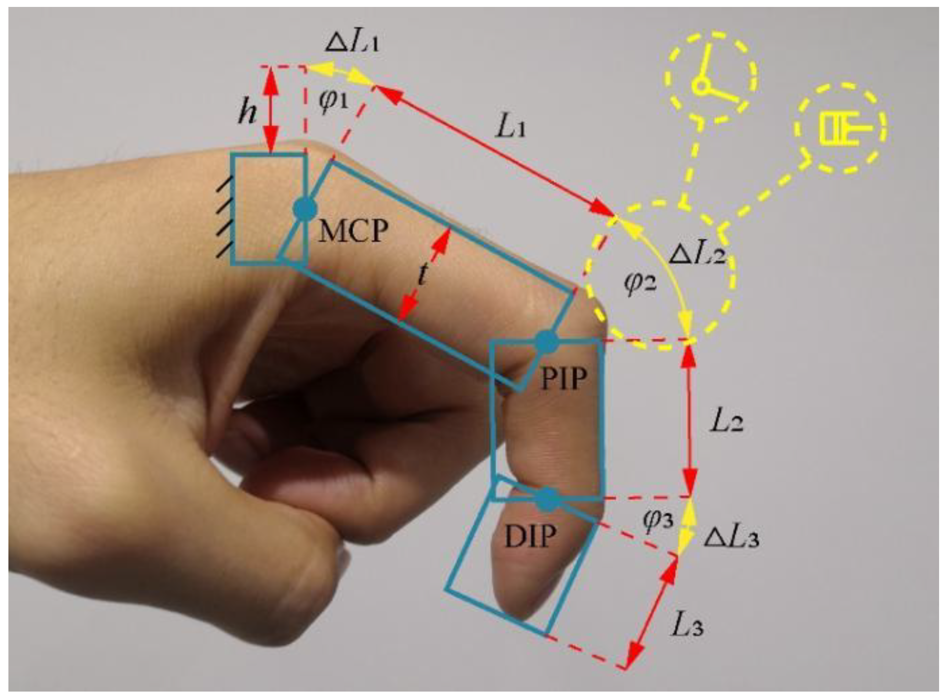
Figure 1. Basic design principle of hand exoskeleton.
Applsci 11 10825 g001
Figure 2. Large deflection of a cantilever beam subjected to a combined end force and moment.
Applsci 11 10825 g002
Figure 3. Large deflection of a VSFH subjected to a combined end force and moment.
Applsci 11 10825 g003
Figure 4. Human-machine coupling model based on human finger and V.
Applsci 11 10825 g004
Figure 5. Relationship between stretching force and assembly angle.
Applsci 11 10825 g005
Figure 6. Components of the novel hybrid-driven compliant hand exoskeleton. (Volar and dorsal body of the hand exoskeleton are on the left and right, respectively).
Applsci 11 10825 g006
Figure 7. Experiment setup for measuring the stretching force of VSFH.
Applsci 11 10825 g007
Figure 8. Results of the stretching force of VSFH for stroke patients.
Applsci 11 10825 g008
Figure 9. Results of flexion angles of VSFH and CSFH with different directions of the force (F0,max = 4 N) results of the stretching force of VSFH for stroke patients.
Applsci 11 10825 g009
Figure 10. Experiment setup for recording the index finger motion with six rippled markers.
Applsci 11 10825 g010
Figure 11. Results of finger flexion angle of different passive stretching forces.
Applsci 11 10825 g011
Figure 12. Measurement (a) and results (b) of the index fingertip force when grasping a cylinder with a diameter of 68 mm.
Applsci 11 10825 g012
Figure 13. Measurement (a) and results (b) of the index fingertip force when grasping a cylinder with a diameter of 50 mm.
Applsci 11 10825 g013
Table 1. Design Parameters of Hand Exoskeleton.
ParameterValue
φ1, φ2, φ330°, 60°, 45°
L1, L2, L345 mm, 25 mm, 20 mm
t15 mm
lj20 mm
h7 mm
bh7 mm
wi0
Publisher’s Note: MDPI stays neutral with regard to jurisdictional claims in published maps and institutional affiliations.