Review

Resurgence of a Nation’s Radiation Science Driven by Its Nuclear Industry Needs

by
Laura Leay
1,
Aliaksandr Baidak
1,2,
Christopher Anderson
1,2,
Choen May Chan
3,
Aaron Daubney
4,
Thomas Donoclift
5,
Gemma Draper
6,
Ruth Edge
1,
Jeff Hobbs
4,
Luke Jones
7,
Nicholas J. S. Mason
1,
Darryl Messer
8,
Mel O’Leary
1,2,
Robin Orr
9,
Simon M. Pimblott
10,
Samir de Moraes Shubeita
1,
Andrew D. Smith
1,
Helen Steele
4,
Paul Wady
11 and
Frederick Currell
1,2,*
1
The University of Manchester’s Dalton Cumbrian Facility, Westlakes Science Park, Moor Row, Cumbria CA24 3HA, UK
2
Department of Chemistry, The University of Manchester, Oxford Road, Manchester M13 9PL, UK
3
Jacobs, Walton House, Birchwood Park, Faraday St., Warrington WA3 6GA, UK
4
Sellafield Limited, Seascale, Cumbria CA20 1PG, UK
5
Scottish Universities Environmental Research Centre, Rankine Avenue, Scottish Enterprise Technology Park, East Kilbride G75 0QF, UK
6
ISIS Pulsed Neutron and Muon Source, STFC, Rutherford Appleton Laboratory, Harwell, Didcot OX11 0QX, UK
7
National Nuclear Laboratory, Havelock Road, Derwent Howe, Workington, Cumbria CA14 3YQ, UK
8
TÜV SÜD Nuclear Technologies, Ennerdale Pavillion, Westlakes Science and Technology Park, Ingwell Dr, Moor Row, Cumbria CA24 3JZ, UK
9
National Nuclear Laboratory, Seascale, Cumbria CA20 1PG, UK
10
Idaho National Laboratory, 1955 N. Fremont Avenue, Idaho Falls, ID 83415, USA
11
Diamond Light Source, Diamond House, Harwell Science and Innovation Campus, Didcot OX11 0DE, UK
*
Author to whom correspondence should be addressed.
Appl. Sci. 2021, 11(23), 11081; https://doi.org/10.3390/app112311081
Submission received: 1 October 2021 / Revised: 21 October 2021 / Accepted: 26 October 2021 / Published: 23 November 2021
(This article belongs to the Special Issue Applied Radiation Chemistry: Theory, Methods and Applications)

Abstract

:
This article describes the radiation facilities and associated sample preparation, management, and analysis equipment currently in place at the Dalton Cumbrian Facility, a facility which opened in 2011 to support the UK’s nuclear industry. Examples of measurements performed using these facilities are presented to illustrate their versatility and the breadth of research they make possible. Results are presented from research which furthers our understanding of radiation damage to polymeric materials, radiolytic yield of gaseous products in situations relevant to nuclear materials, radiation chemistry in light water reactor cooling systems, material chemistry relevant to immobilization of nuclear waste, and radiation-induced corrosion of fuel cladding elements. Applications of radiation chemistry relevant to health care are also described. Research concerning the mechanisms of radioprotection by dietary carotenoids is reported. An ongoing open-labware project to develop a suite of modular sample handling components suited to radiation research is described, as is the development of a new neutron source able to provide directional beams of neutrons.

1. Introduction

At present, interest in radiation science is mainly driven by the needs of the nuclear industry to understand the processes occurring inside reactors and packaged nuclear materials. Even before the birth of the nuclear industry, the effects of radiation have been studied for applications to medicine and chemistry. The race for atomic weapons in the 1940s led to a period of rapid expansion of radiation research, which continued through the next few decades as uses for radiation were found for material processing. During World War II, particle accelerators were extensively used as sources of radiation and the introduction of nuclear reactors provided more complex radiation fields. The intense, multi-mode irradiation found in the nuclear industry merited intense study, not only to understand how nuclear systems change with time and use, but to better understand how radiation can be used in health applications, materials science, and chemistry.
British scientists were at the forefront of the development of nuclear energy, with the world’s first commercial-scale nuclear power reactor starting up in the UK in 1956 [1]. A rapid period of publicly funded growth of nuclear energy followed, with the country establishing the facilities and skilled people to operate a closed fuel cycle, one of only a very small number of countries to do so. Through the 1980s and 1990s, there was a marked change in the political approach to nuclear energy, with decisions to privatize much of the industry and withdraw public sector support for the construction and operation of new nuclear power stations [2]. A consequence of this approach was a reduction in investment in nuclear research and development, and a corresponding gradual erosion of essential skills [3]. One area to suffer greatly from this loss of expertise in the UK was radiation science; a detailed understanding of the interactions between radiation and matter is crucial to all aspects of the nuclear fuel cycle.
In 2005, the Nuclear Decommissioning Authority (NDA) was created by the UK government to take over ownership of the nation’s legacy nuclear plant and facilities [4]. The newly formed NDA recognized the need to invest in the development of skills required to deliver a program of work that would last for more than a century. The NDA also recognized that radiation science was an area lacking in the depth and resilience of both expertise and facilities that would be required.
To address the above concern, the NDA began looking for a partnership with research-focused universities, which led to a formal collaboration agreement with The University of Manchester, signed in 2006. This agreement committed the parties to invest and work together to strengthen high-level skills in the area of radiation science. A new research center for radiation science for the university was created, a center that would allow academia and industry access to the facilities and expertise to create new knowledge in radiation science. This facility, the Dalton Cumbrian Facility (DCF), opened its doors in 2011 and quickly established itself as being of strategic national importance in addressing nuclear legacy challenges, as well as developing and validating materials for future reactor technologies [5]. The facility now has a well-established user community of over 70 universities and companies, carrying out research in sectors as diverse as nuclear energy and healthcare [6]. In the early days of DCF, the resident researchers were pioneers helping to establish a brand-new capability for the nation and many of those researchers have continued to pursue a career in the nuclear industry or in radiation science. The capabilities and expertise at DCF continue to grow. The following sections describe established capabilities and some examples of their applications in both the nuclear industry and healthcare before emerging capacities are presented.

2. Review of Established Capabilities

The expertise and capability at DCF are constantly expanding. In the last ten years, the original capability provided by a single particle accelerator has been complemented by the addition of a second accelerator and each of the beamlines has been developed for specific applications. The irradiation capability using photons has also improved; the 60Co gamma irradiator is now complemented by a cabinet X-ray irradiator to provide a wider variety of photon energies and dose rates. The suite of stand-alone analytical capability has also grown.

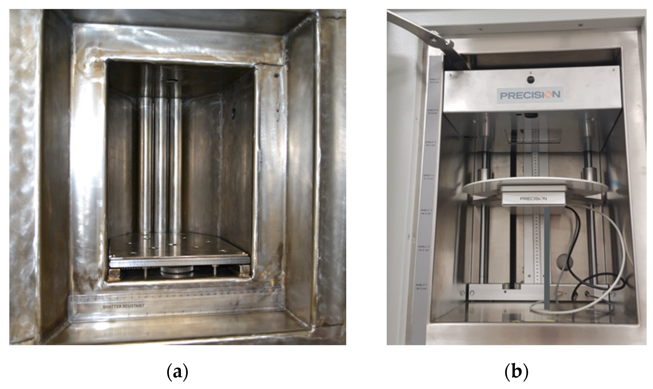
2.1. Gamma and X-ray Irradiators

The DCF 60Co gamma irradiator is a self-contained Foss Therapy Services Model 812 with a 9 L sample chamber, shown in Figure 1a, and has previously been described elsewhere [7]. All three source rods are currently loaded, and the activity is evenly distributed along the length of the source rod. There are five attenuator shields, each providing a dose reduction factor of two such that maximum attenuation provides ×32 reduction. The dose to samples can be further reduced by using only a single source channel. Due to the inevitable decay of the 60Co over time, the dose rate of this source changes, being at a maximum of 500 Gy/min just after a reload. In September 2021, the possible range of absorbed dose rates was from ~0.1 Gy/min to ~270 Gy/min depending on the location in the chamber and attenuation. Two shielded service ports are available which enable cabling or tubing for in situ electronics measurements and/or sample monitoring. A turntable can be centered at 10 or 15 cm from the sources with central dose rates of ~77 and ~45 Gy/min, respectively (September 2021). Irradiations can be carried out at cold temperatures in dry ice or liquid nitrogen using a sample Dewar so that short-lived radical species can be trapped, allowing their migration and decay to be monitored as the temperature is gradually increased.
A recent addition to the irradiation capability at DCF is a model MR350 cabinet X-ray irradiator (manufactured by precision X-ray irradiation) which is complimentary to the 60Co gamma irradiator: an electron beam is accelerated onto a tungsten plate to produce X-rays, mostly through Bremsstrahlung. As a result, a broad X-ray spectrum is produced rather than the narrow high-energy spectrum produced by the gamma irradiator. The X-ray irradiator provides a lower dose rate and sample penetration than the 60Co gamma irradiator while also providing greater flexibility of irradiation conditions as well as a much bigger sample chamber, shown in Figure 1b. The acceleration can be changed from 30 to 350 kV with the peak in the X-ray spectrum at roughly a third of this energy. The current it can produce ranges from 0.1 to 30 mA, although the total power of the electron beam can never exceed 4 kW. The sample position can be changed along with the electron current to produce dose rates from 140 Gy/min downwards. Automatic dose rate sensing, a range of apertures, and a turntable to improve dose homogeneity are available. Insertion chambers can be used to change the gas atmosphere (e.g., CO2 or hypoxic) whilst access ports allow for connection to external instruments.

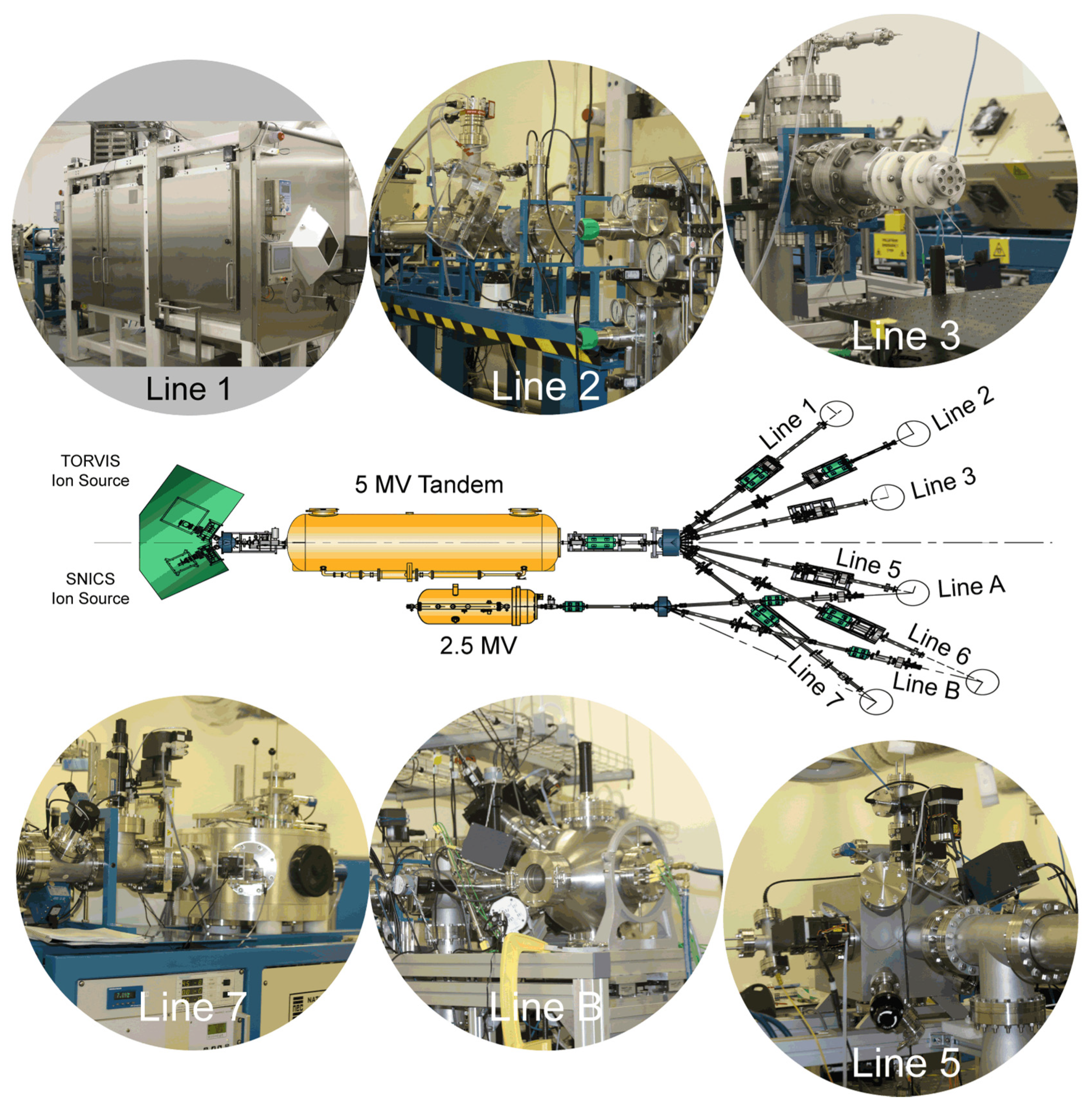
2.2. Accelerator Systems

The DCF ion beam accelerator facility comprises a pair of electrostatic Pelletron accelerators manufactured by the National Electrostatics Corporation (NEC), a 5 MV tandem 15SDH-4 and a 2.5 MV single-ended 7.5SH-2 accelerator with a suite of six dedicated end-stations contained in two independently shielded and interlocked target rooms. The beam lines from the 2.5 MV accelerator meet two of the beam lines from the 5 MV tandem to provide common locations to allow beams from both accelerators to be combined in future dual-beam experiments. To avoid confusion, the text uses beam-line numbers from the 5 MV tandem to refer to the end stations, which each have unique capability.
The 5 MV tandem has a choice of two ion sources at its low energy end: a toroidal volume ion source (TORVIS [8]) capable of generating up to 100 µA of proton current, or 1 µA of He ion (alpha) current; a second, multi-cathode source of negative ions by cesium sputtering (MC-SNICS) for the production of heavy ion beams [9]. The MC-SNICS source uses a custom cathode wheel from NEC with 20 cathode positions, each taking a 6 mm diameter cathode. This large cathode diameter gives high volumes of cathode material with long lifetimes—over 50 h of continuous beam production at constant current is typical. Having many cathodes installed on the wheel at the same time means that switching to a fresh cathode is very quick, and a selection of different ion species can also be readily available. Due to the tandem design of the 5 MV accelerator, it can deliver protons beams of up to 10 MeV, alpha beams of up to 15 MeV, and heavy ions to a maximum of 35 MeV in energy.
The 2.5 MV single-ended accelerator is equipped with a positive RF plasma ion source within its terminal shell. This is primarily a source of high-current proton or He ion (100 µA each) beams, although other noble gas ion beams have been routinely produced; krypton and xenon ion beams have proved popular for simulating radiation damage within nuclear fuels or fuel surrogates as these ions are common fission products produced during nuclear fuel burn-up.
At the high energy end of each accelerator is a dipole switching magnet which can direct the accelerated ion beam into the desired beamline. Whilst each accelerator can only supply an ion beam to a single beamline at a time, having a choice of beamlines allows for a variety of dedicated end-stations to be permanently provided. The layout of the accelerator complex and relation of the various beamlines are depicted in Figure 2.
Line 1: To cater for the very high levels of prompt radiation (gamma and neutron) generated by high current, high energy proton irradiations (up to 100 µA at 10 MeV), this beam line is designated for high damage studies using high energy proton beams and so is equipped with an irradiation end-station inside its own hotcell. The hotcell is a radiation enclosure that complements the concrete shielding of the target room, funded as an EPSRC (Engineering and Physical Sciences Research Council) National Nuclear User Facility (NNUF). A second, attached, shielded enclosure allows for irradiated samples to be demounted remotely. Such samples, following prolonged high-dose, high-energy proton irradiation can be activated to a level that requires either local, shielded storage—provided for in the hotcell—or to be safely loaded into a shielded ‘croft’ pot for transport to an active handling lab for subsequent analysis.
Line 2: The only beam line not to have its own dedicated end station. This allows for users with their own experimental vessels to interface them to the DCF ion beam accelerators. The fitting of fast reaction (35 ms response) valves in this beam line allow for more direct coupling to liquid or gas filled enclosures, such as those proposed for in situ corrosion studies, or simulation of radiation chemistry in deep-space ice cores.
Line 3: In counterpoint to the high-dose studies undertaken on Line 1, this line caters for a low dose rate (few nA), although at high-energy irradiations for radiation chemistry studies. This is fitted with a LaVerne-type collimator and exit window to allow for ex-vacuum irradiations to take place on liquid or biological samples. The flexible nature of this end station has already been discussed previously [7].
Line 5: At present, this has an end station for radiation damage that accepts ion beams from the 5 MV tandem only. This will be replaced in 2022 with a new end-station, currently under development, which will accept simultaneous beams from both the 5 MV tandem and the 2.5 MV single Pelletrons. The dual beam capability will allow for hydrogen or helium loading of a sample to take place from the 2.5 MV whilst at the same time the sample is undergoing heavy ion radiation damage delivered from the 5 MV accelerator. Such studies are of great interest in understanding the behavior of structural materials in nuclear plant and in nuclear fuel. The mechanics of the damage process can influence the hydrogen or helium distribution in high proton or alpha flux environments. In structural materials, the main concern is helium embrittlement [10,11], whereas in nuclear fuel, both chemical damage and swelling are of interest [10,12]. The new vessel is designed to take our current range of radiation damage stages [13] but can also be easily adapted to accept custom in-vacuum stages proved by our various user groups.
Line 6: Line 6 does not currently have an end station installed as the end position is used by a radiation damage-end station that takes ion beams from Line B on the 2.5 MV single-ended accelerator (see Figure 2). Similar to Line 5, this will be upgraded in 2022 to have a dual beam capability with beams from both accelerators delivered to samples simultaneously. This end-station will, however, also include two major analytic tools. The irradiation part of the chamber will also feature a compact SIMS (secondary ion mass spectrometry) head from Hiden-Analytic. This is equipped with a 5 keV ion etch gas gun and a 0–300 amu quadrupole mass analyzer. It is not envisaged that SIMS measurements will be taken during ion beam irradiation; rather, this will be paused to allow the SIMS head to collect a depth profile from a 40 µm diameter spot. If repeated depth profiling during a long irradiation is desired, it will be a simple matter to pause the irradiation and collect a SIMS measurement from a fresh location on the sample. Additional to the irradiation chamber will be a second chamber containing a SPEC Phobios 150 hemispherical analyzer for high-energy reflection electron energy loss spectroscopy (HR-EELS). The electron source for this is a Staib EF-1201 nano-focus electron gun capable of providing 12 keV electrons with a 150 nm focus. This combination offers the prospect of spatial imaging with EELS spectra covering K-edge core hole spectra for elements up to and including the 3-d transition metals, and L-edge spectra for higher-z elements. Using this set-up, spatially resolved changes in the chemical structure at material surfaces as a result of ion beam radiation-induced damage will be possible. The two analysis chambers can be accessed by the sample under investigation, which will be mounted on a sample stage on a single linear transfer arm. Following the commissioning of these two new end-chambers, their performance will be detailed in a further publication of their own.
Line 7: This is home to an NEC RC43 ion beam analysis end station and is capable of a variety of ion beam analysis (IBA) techniques, including PIXE (particle-induced X-ray emission), RBS (Rutherford backscattering spectroscopy), ERD (elastic recoil detection) and NRA (nuclear reaction analysis). Using ions from the tandem accelerator allows for both protons and alpha particles to be used as the probe ion, whilst the wide energy range available provides scope to tune the probe ion energy to specific resonances to enhance the IBA signal.
The DCF’s ion accelerator capabilities have so far enabled a wide variety of studies that aim to understand the radiation-induced property changes in materials of interest for fission and fusion plants. Proton beams are commonly used as a surrogate for neutron damage in reactor core materials with the advantage of providing higher damage rates when compared to neutrons, allowing for relatively high damage levels in short periods of time. Heavy ions are of particular interest in radiation damage studies as although their range in a material is limited, they create large amounts of damage in their short path. Some of these studies include candidate materials for plasma-facing walls and structural materials in fusion reactors [14,15,16,17], structural components for fuel assemblies inside nuclear cores [18,19], as well as investigation of potential new materials for use in such extreme environments [20,21].

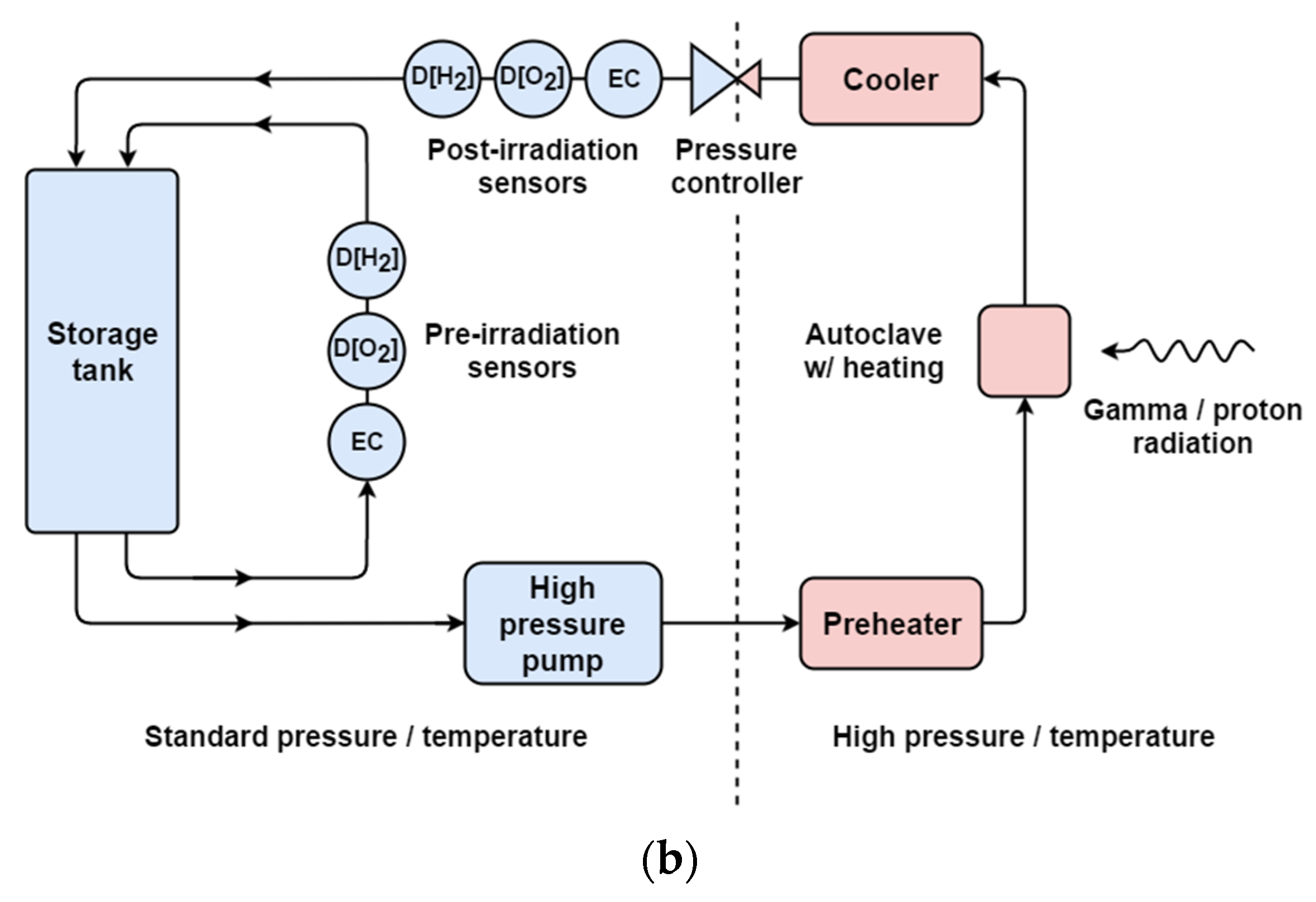
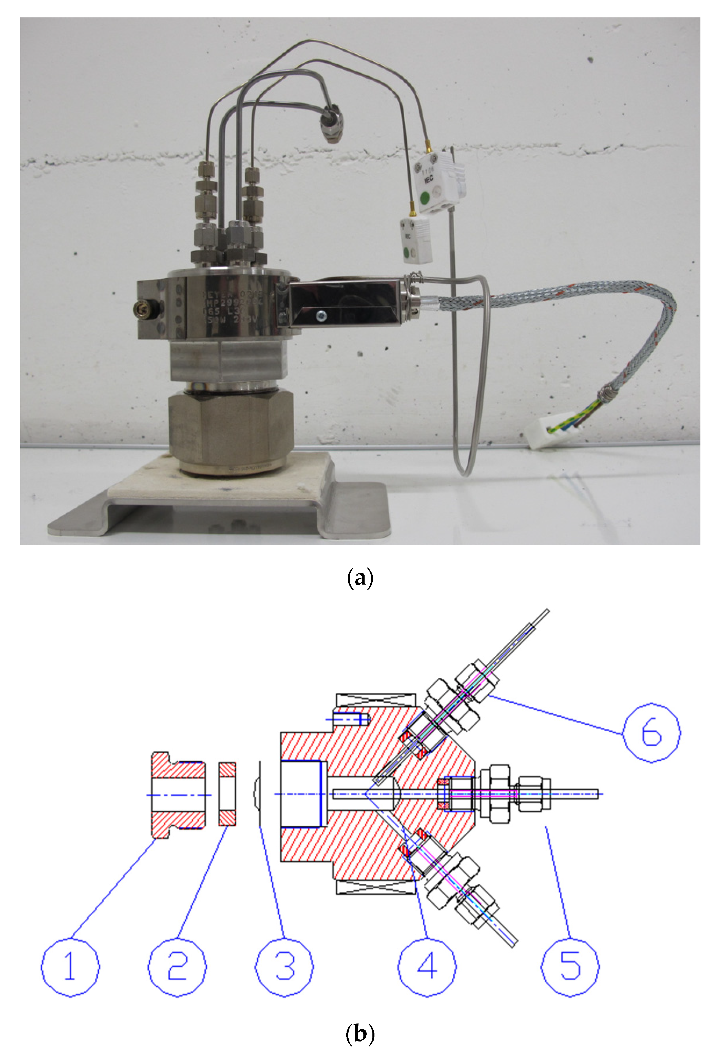
2.3. Recirculation Loop

Water radiolysis and corrosion under extreme conditions of high temperature and high pressure (HTHP) can be investigated using a water recirculation loop, shown in Figure 3a, which was purpose-built by Cormet™ Oy (Vantaa, Finland). Researchers at DCF commissioned the recirculation loop with four irradiation autoclaves; two are designed for gamma irradiation while the other two are dedicated for ion beam irradiations. The recirculation loop is a mobile station, which can be easily moved between the 60Co irradiator room and ion beam target rooms.
Figure 3b shows a schematic diagram of the recirculation loop. The flow system incorporates a 10 L feed tank. Dissolved oxygen or hydrogen concentration can be measured in the range of 0–1000 ppb using Hach™ Orbisphere sensors. Water conductivity is measured using two conductivity amplifiers from ABB™, accurate up to 10 μS/cm. All four autoclaves incorporate temperature monitoring and control and are able to withstand temperatures up to 350 °C and 220 bar of pressure.
Advanced control of the fluid flow enables different modes of operation. The simplest case is system conditioning. In this mode, an aqueous solution is continuously sparged with the gas of choice, e.g., high-purity argon, nitrous oxide, etc.; and the liquid simply circulates in a closed loop until equilibrium conditions are reached. Alternatively, irradiated liquid can be collected for analysis using the once-through operation mode. For corrosion tests, water flow can be directed through a mixed bed ion exchange column in order to generate highly deionized water. If radiolytic gas formation is to be evaluated, irradiated aqueous solution can be first accumulated in a gas stripping device and then purged with suitable high purity carrier gas, e.g., argon, to allow for dissolved gas extraction and subsequent mass-spectrometric analysis of extracted gases.
The wetted parts of each autoclave and all components in the high-temperature part of the recirculation loop are made of Hastelloy C-267 alloy. This alloy is known for its resistance to oxidation and stress corrosion cracking (SCC), and excellent chemical durability at high temperatures. The autoclave shown in Figure 4a has a capacity of 50 mL and has been designed for gamma radiolysis experiments. It features two temperature sensors (K-type thermocouples) and inlet and outlet water lines. The pressure sensor and the safety valve are located outside of the 60Co irradiation chamber. A heater band surrounds the autoclave body and a K-type thermocouple on the heating element monitors the temperature. Hot parts of the autoclave are made of corrosion-resistant Hastelloy C-276.
The autoclave design for ion beam irradiations is shown in Figure 4b. This cell has capacity of only 6 mL. The autoclave has been designed to allow the passage of a proton beam through a thin window (a few tens of microns thick) that separates the beamline and the aqueous solution at HTHP inside the autoclave. The window is a metallic foil made of either C-276 (for radiolysis experiments) or a material under study (for corrosion testing).

2.4. Stand-Alone Analytical Equipment

In addition to the irradiation capability and in situ analytical capability, DCF houses a suite of ex situ analytical equipment. Gas chromatography is used extensively for quantifying gaseous products of radiolysis. Two gas chromatographs from SRI instruments and an Agilent 7890B are set up for different applications. One SRI gas analyzer utilizes the crush tube method [22], and the other is set up for manual injection of samples taken from off-the-shelf Swagelok components [23]. The Agilent 7890B is fitted with a PAL3 autosampler allowing rapid analysis of headspace from crimp-cap vials.
Where radiolysis in confined media is of interest, porous media can be characterized using a combination of techniques. A Micromeritics Autopore V can be used for mercury intrusion porosimetry while a Micromeritics TriStar II 3020 can be set up with one of several gases for the analysis of pores down to 2 nm. Complementary analysis can be achieved using a Micrometrics AcuPyc II 1340 H2 pycnometer. Gas chromatography has been used in conjunction with nitrogen adsorption to investigate radiolytic hydrogen production from other heterogeneous porous media [24]. Pore structures can be further characterized using scanning electron microscopy (Quanta 250 FEG SEM) which is fitted with an energy dispersive X-ray (EDX) spectroscope to aid in determining local chemical differences in a material. EDX has been used to successfully identify the morphology of calcite which formed in cementitious media after irradiation [25]. Further structural characterization is provided by an Empyreon X-ray diffractometer (Malvern Panalytical) and, along with nitrogen adsorption and EDX, has been used to determine microstructural changes in concrete [26].
Further spectroscopic techniques are available to determine radiologically produced chemical changes. Using a Ram II FT coupled to Vertex series FTIR (Bruker), a combination of Raman and Fourier-transform Infra-red (FT-IR) spectroscopy has been used to detect cross-linking and chain scission in a variety of epoxy resins [27] and to establish a link between radiation chemistry and mechanical properties of a variety of 3D printed plastics [28]. Light spectroscopy (Agilent Technologies Cary Series UV-VIS-nIR) has been used for the quantitative measurement of NO2 and HNO2 via the Shinn method, which may commonly be found as a result of radiolysis of nitric acid used in the extraction of useful fission products from used nuclear fuel [29]. Electron paramagnetic resonance (EPR) is available (Bruker EMX nano) to determine radical formation and has been used in conjunction with UV-VIS-nIR spectroscopy to elucidate the mechanisms that lead to unusual radiation-induced color change in glass [30].

3. Exemplar Results

The equipment available at DCF has been used in an impressive array of experiments since it opened its doors in 2011. A large body of work is of direct relevance to the nuclear industry, including studies on chemical systems, electronics, and polymers [7]. The scope of work has evolved with time; applications of radiation research to healthcare are a burgeoning area of expertise. In this section, a variety of results that capture the breadth and depth of research are organized by their main area of application.

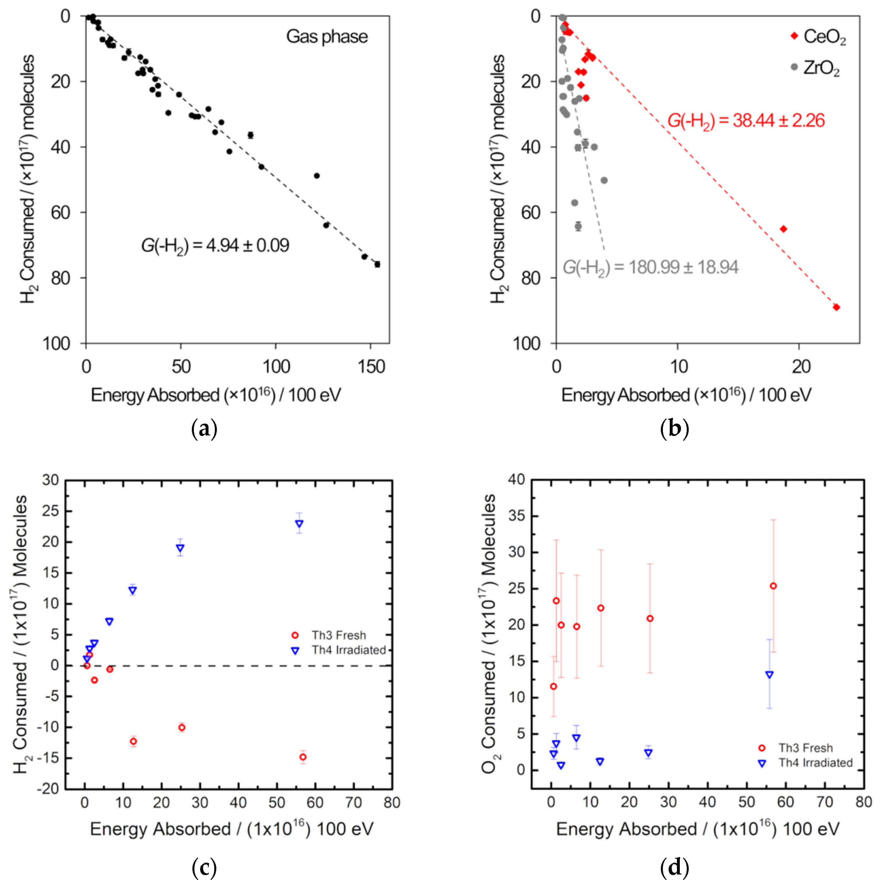
3.1. Sensing of Gases Produced by Radiolysis

One major area of interest for the nuclear industry is the production of hydrogen from radiolysis of water that is in the presence of metal oxides. Such systems are important in both plutonium stewardship and decommissioning of Magnox waste ponds.
The sludge in Sellafield’s Magnox waste ponds contain Brucite (Mg(OH)2) which is subject to radiation emanating from the radioactive species present in the waste. Proper understanding of both the production of hydrogen and the rheological properties of these sludges is important for the storage, transport, and processing of this legacy waste.
Understanding the role of water-oxide interfaces in radiolytic hydrogen production and the evolution if gases in contact with the oxide also underpins safe plutonium stewardship—the UK’s stockpile of plutonium dioxide is currently stored in sealed cans. Since work on plutonium would require specialist active handling facilities, surrogates can be used at DCF, which will add insight into the wider field of radiolysis in the presence of an oxide surface.
Recent developments in hydrogen probe technology [31] have provided new means to detect hydrogen. However, since these probes are highly sensitive to radiation, it is necessary to ensure they are not subject to the direct radiation field [32]. These probes have been used as an economic, parallelizable, and compact alternative to gas chromatographs in a range of experiments. Further work involves the calibration of the gas probes to also quantify amounts of oxygen. Examples of the kinds of measurements being undertaken in a series of ongoing research programs concerning the role of the role of water-oxide interfaces in radiolytic hydrogen production are shown in Figure 5.
Electrochemical hydrogen gas probes have been used to measure the production of hydrogen from a magnesium hydroxide/water mixture by proton irradiation (mimicking the alpha irradiation field produced by decay of uranium). For this experiment, the sample mixture was sealed in a metal sample chamber with a 5 μm aluminum window and a Unisense hydrogen probe [31] was attached via a Swagelok fitting. The sample chamber was placed so that the radiation beam passes directly through the foil window. The samples were irradiated with 5 MeV protons with a 1.3 nA current. This irradiation was performed with the chamber full of a mixture (11 ± 5) % (w/w) of magnesium hydroxide and water. A separate experiment was performed on a 0.1 mM potassium bromide solution.
The response of the hydrogen probe to four sequential ion irradiations of the sample is plotted in Figure 5a. The hydrogen probe response is clearly delayed after the start of irradiation indicating that the hydrogen takes time to diffuse out of the sample into the headspace of the chamber i.e., to reach equilibrium between the liquid and the gas. Although each irradiation is essentially identical, there is a clear decline in the hydrogen production rate, indicating radiation-induced hydrogen consumption. This experiment shows the hydrogen probe’s potential for real-time hydrogen monitoring and measurement of hydrogen yields from ion irradiations. Figure 5b shows results from both the magnesium hydroxide and potassium bromide solutions. The increase in the hydrogen probe signal per unit energy deposited in for the magnesium hydroxide sample was 5.69 ± 0.03 times the increase when the bromide solution was irradiated.
Gas probes, off-line gas chromatography, and Orbisphere sensors are routinely used at DCF to determine radiation-induced changes in gas composition. Examples of radiolytic consumption of H2 and O2 are provided in Figure 6 for several metal oxides exposed to gamma radiation.
Off-the-shelf metallic components were used to build the sample assembly, which included a 10.5 cm3 sample vessel and a single inlet/outlet fitted with a bellows sealed valve [23]. Figure 6a,b shows the results of the gamma irradiation of a 5:5:90 H2-O2-Ar mix at 1 bar without any metal oxide present and in the presence of either ceria or zirconia and supports the results of studies of PuO2 [33,34]: under irradiation, H2 combines with O2, and this depletion happens more readily in the presence of a metal oxide [23]. Measurement of the H2 concentration post-irradiation was conducted using an SRI gas analyzer fitted with a 1 mL sample loop, X13 molecular sieve column, and thermal conductivity detector. The sample vessel was connected directly to the sample loop, which is fitted with a pressure transducer so that the amount of gas in the sample vessel is known after irradiation. Figure 6a,b indicates that a steady state between the radiolysis of water adsorbed onto the surface of the metal oxide and the recombination of H2 and O2 is not reached. Analysis of a 1:1:98 H2-O2-Ar mix gamma irradiated over thoria using the same off-line gas chromatography set-up is shown in Figure 6c,d [35]. In these experiments, O2 depletion as well as H2 depletion was determined. A fuller explanation of the effects observed in the thorium oxide system will be published elsewhere.
These experiments show that there are rich dynamics waiting to be explored, which involves radiolytic production, depletion, and radiation aging of samples. What is needed is a systematic approach to studying these phenomena whereby a longitudinal study could be made in order to investigate radiolytic processes in both liquid and headspace as well as the effects of solid-phase radiation damage on sample aging. Use of the gas probes to take measurement in situ is the first step towards uncovering these rich dynamics. Adaptation of the gas probe system for flexible and efficient gamma irradiation studies is underway (see Section 4.1).

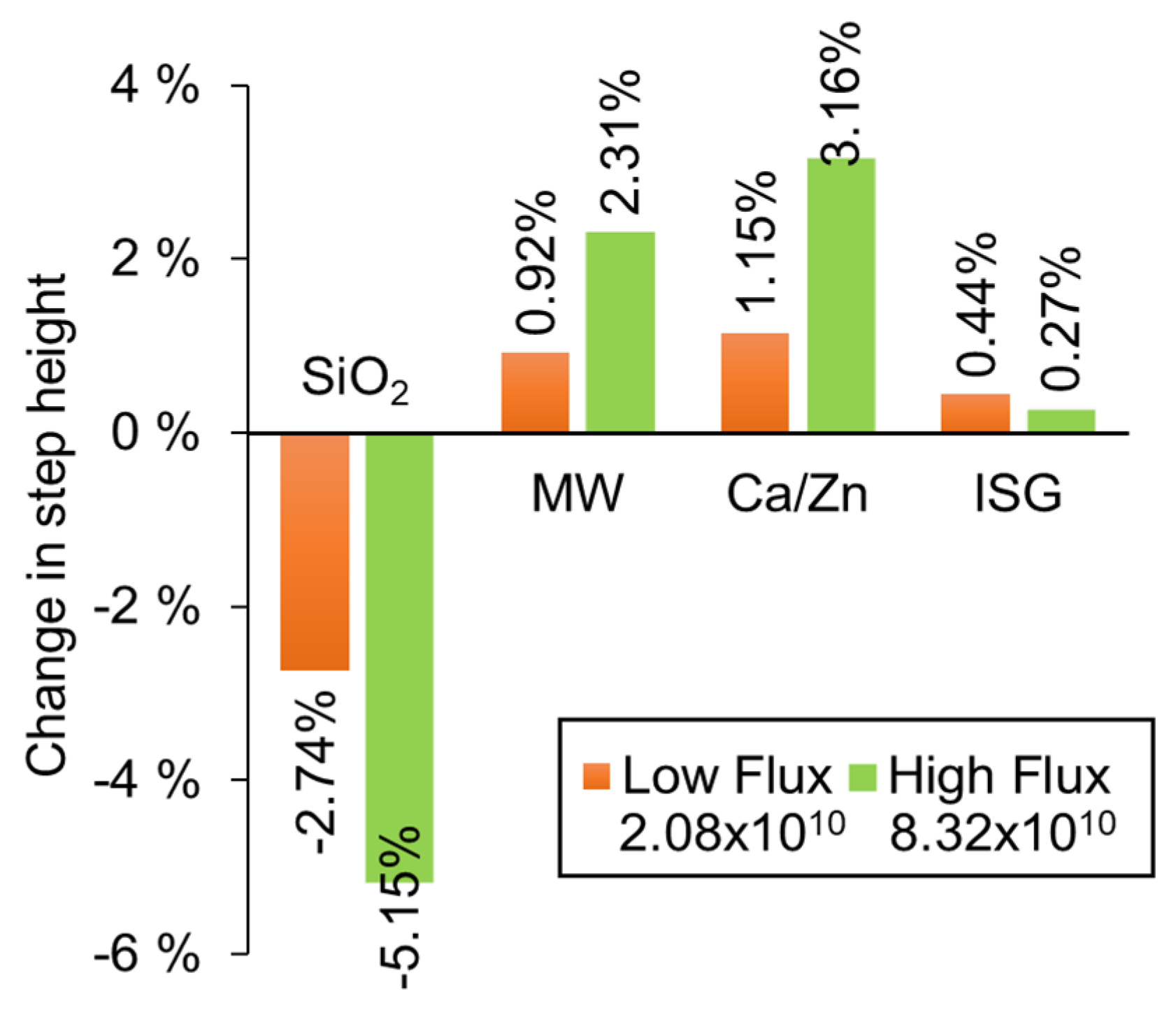
3.2. Materials Chemistry for Nuclear Waste Immobilisation

High-level waste (HLW) generated by the nuclear industry is incorporated into a glass and the effect of radiation on this glass must be understood for the industry to have confidence in this waste immobilization method. Glass samples of relevance to the nuclear industry were produced at Sheffield Hallam University and the compositions are provided in Table 1. MWsection and Ca/Zn are similar to the base glasses used in the UK [36] while ISG refers to the International Simple Glass [37]. Vitreous silica samples were purchased from Galvoptics Ltd. To prepare all four glasses for ion irradiations, one 25 by 25 mm face was hand polished using diamond lapping films to produce surfaces with <100 nm roughness. Four samples were loaded into a custom build sample holder for 14 MeV Ni ion beam irradiation (fluence of 4.56 × 10¹⁴ ions/cm2). The holder masked part of each sample from the ion beam so only a 5 mm by 5 mm area of each sample was irradiated.
Profilometry (Bruker Contour Elite K with Multimode 8 AFM System at the University of Sheffield) provided optically gathered 3D surface maps of the border between the irradiated and unirradiated sample areas. Step heights were calculated as a percentage of the penetration depth of the incoming ion beam, as reported by SRIM-2013 [38] (Table 1), using the mean step height from seven measurements at different points along the border.
Figure 7 shows that vitreous silica compacted under ion beam irradiation, whereas all other glasses expanded. The change in volume of the silica corresponds to values recorded in other literature [39,40,41]. For both the MW and Ca/Zn glass, a fourfold increase in ion beam flux leads to a twofold increase in the degree of swelling. A much smaller volume change was observed in ISG such that the effect of altering the flux is not clear. The structure of these glasses comprises a network of tetrahedral units (SiO4, AlO4, BO4) and trigonal (BO3) units. Network modifiers (Na, Li, Ca, and Zn) exist in the glass as somewhat free-floating ions that charge compensate non-bridging O atoms, and in the case of ISG, also charge compensate for Al in the glass network. The different responses suggest that glass chemistry plays a part in their radiation response. The expansion of the UK base glasses suggests that the network is depolymerizing and so producing more dangling bonds, which may be influenced by the reorganization of the mobile network modifiers in response to the ion beam. The trend with flux suggests that the chemical changes that lead to the volume change are dose rate dependent. Further work will probe these chemical changes using, for example, Raman and NMR spectroscopies.
Work is also underway at DCF, focusing on understanding the interplay between radiation and the crystalline phases that are present in waste form [36]. Complementary work will probe how radiation affects leaching in anoxic groundwater, in a disposal scenario where the canister housing the glass has begun to corrode. Similar work has previously been carried out under oxic conditions [42]. Such studies will provide confidence in understanding how the waste form will evolve over the long timescales (hundreds of thousands of years) relevant to geological disposal of radioactive waste.

3.3. Applications of Radiation Science to Healthcare

Radiation chemistry in aqueous systems is an ongoing area of research at DCF which has applications beyond the nuclear industry; healthcare is one example of this wider application. The redox conditions generated during radiation therapy can damage human cells, so investigation is required to understand how healthy cells can be protected. Radiation chemistry also offers a novel approach to studying in vivo processes: many of the free radicals that can be generated radiolytically are also present in vivo during normal metabolic processes and are over-produced during oxidative stress. Work at DCF was inspired by clinical studies of dietary supplementation to help prevent oxidative stress, and subsequent diseases such as cancer, where a pro-oxidant effect could not be explained [43].
Several dietary carotenoids (CAR) have been shown to give protection to human lymphoid cells from damage by γ-radiation, after two weeks of dietary supplementation with 70–90 mg/day of an individual carotenoid [44,45]. This protective effect declines as the oxygen concentration increases, and the rate of decline depends on which carotenoid is administered. Remarkably, for the carotenoid lycopene (the red pigment in tomatoes), no protection at all was observed at 100% oxygen, falling from 5-fold protection in air and 50-fold protection in the absence of oxygen. It is postulated that the link between oxygen concentration and cell protection is mediated by an initial addition of a hydroxyl radical (OH) to CAR, followed by the addition of oxygen to the radical adduct (CAROH) forming a more damaging peroxyl radical (CAROH-OO). This series of reactions is outlined in Equations (1)–(3) and is known as the oxygen effect.
CAR + OH → CAROH
CAROH + O2 ⇌ CAROH-OO
CAROH-OO + cell → cell death
To assist in understanding the underlying radical-based mechanisms of the cellular results described above, the effect of gamma radiation on carotenoids in solution has been studied using a total dose of 25 Gy. The dietary carotenoids studied in the cellular work are lipid soluble, so detergent needs to be used to solubilize them in water. Astaxanthin was solubilized in aqueous 2% Triton-X 100 detergent. Crocetin, a water-soluble carotenoid, was also studied to eliminate any effects of the detergent. Damage of the carotenoids is indicated by bleaching, determined using UV-Vis spectroscopy. Radiolysis of air-saturated water generates oxidizing and reducing species, including OH and superoxide (O2•−). Bleaching of carotenoids in essentially oxidizing conditions was studied using nitrous oxide to convert electrons generated during radiolysis to OH. A separate study of air-saturated formate (NaCO2H) solutions was carried out to investigate the role of O2•−, since in the presence of air, NaCO2H converts all the primary radicals, eaq, OH and H, to O2•− [46]. Sodium formate was used at a concentration of 0.1 M. The results are shown in Figure 8.
For the formate systems, Figure 8 shows that there is a small but detectable reduction in absorbance for astaxanthin in air-saturated aqueous Triton-X 100 solution compared to an un-irradiated sample. We obtain similar results for crocetin in water (Figure 8b) which shows that there is no effect of the Triton detergent associated with the rather low reactivity of carotenoids with O2•−. In cellular studies, O2•− was also shown to play no role in the oxygen effect by studying the effect in the presence of superoxide dismutase (SOD) [45].
For the air-saturated system wherein formate was not added, the results in Figure 8 correspond to astaxanthin or crocetin bleaching of approximately 35%, demonstrating an increase in the reactivity of carotenoids with OH compared to O2•−. A further substantial bleaching of both astaxanthin and crocetin is observed in the nitrous oxide system, wherein the concentration of OH is doubled. Ignoring the very small bleaching due to O2•− in this system, a doubling of the amount of carotenoid bleached compared to the air saturated system should be expected: instead, we see that only about 60% of the carotenoids are bleached due to the bimolecular reaction, OH + OH → H2O2 (rate constant, 2k = 1.1 × 10¹⁰ M−1s−1) [47], which also occurs: doubling the concentration of OH increases the significance of this reaction by a factor of four.
To further understand the mechanism of the effect of oxygen concentration on cell protection, the bleaching of crocetin in mixtures of N2O and oxygen after a 25 Gy gamma irradiation has also been studied. The concentration of crocetin fell by 8.4, 18.0, 22.0, 25.5, and 26.6 % as the oxygen concentration increased from 0% to 10, 20, 50, 60, and 80% oxygen. That is, damage (bleaching) due to reaction with the radicals formed is enhanced by the presence of oxygen.
These radiation chemistry solution studies support the molecular mechanism suggested for the oxygen effect (i.e., reactions (1)–(3), above). Overall, the cell studies indicate the equilibrium constant for (2) is highest for lycopene, followed by β-carotene, zeaxanthin, and astaxanthin, and is lowest for lutein [45]. Administering dietary supplements in the weeks prior to radiation therapy could improve patient outcomes, and these results form one part of an extensive suite of work to understand the role of radiation chemistry in cell death and survival. Furthermore, radiation chemistry can be used to probe the effect of radicals produced during normal metabolic processes.

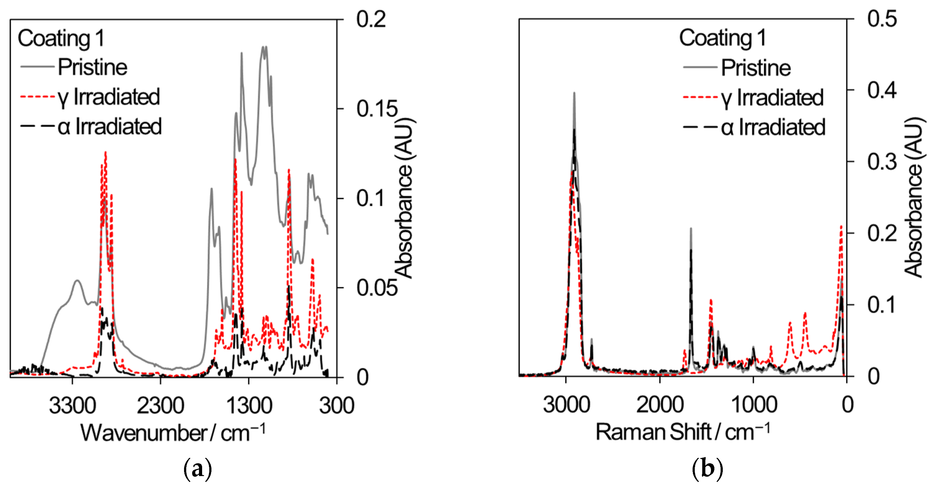
3.4. Commerical Polymeric Materials of Interest to the Nuclear Industry

Two polymeric materials are being considered for different applications in the nuclear industry: the decontamination of surfaces by strippable coatings and the 3D printing of components or hand tools. In decontamination, the removal of radioactive particles from the surfaces of large items such as concrete walls has the potential to reduce waste volumes. Commercial strippable coatings may be used for surface decontamination and three samples have been selected for comparative gamma and 5.25 MeV He ion irradiation, based on an initial sift of twelve different coatings that were subjected to gamma irradiation only. [48]. All samples were irradiated to a total dose of 500 kGy. Samples for gamma irradiation were loaded into 20 mL crimp-capped glass vials filled with laboratory air and received a dose rate of ~80–90 Gy/min. Samples for He ion irradiation were loaded into a bespoke sample cartridge and irradiated in vacuum using a rastered ion beam until an accumulated charge of 285 μC was reached. Analysis using FT-IR and Raman spectroscopy, shown in Figure 9, revealed that coating 1 exhibited a loss of absorption across many wavelengths indicative of depolymerization and, in the case of gamma irradiation, reacted with air to develop nitrogen-containing functional groups (Raman peak shifts at 450 cm−1 and 625 cm−1). Coating 3 showed less change in absorption while coating 8 showed very little change in absorption; hence, it is the most promising strippable decontamination coating for applications to the nuclear industry.
A similar study has been conducted on fused filament fabricated (i.e., 3D printed plastic) materials and the chemical changes as a result of radiation have been compared to changes in mechanical properties. [28] Although a variety of filament compositions are available commercially, two types deserve attention here: PLA (polylactic acid) is a very common choice of filament that has been found to perform poorly under irradiation while a filament based on nylon was seen to perform best, under the conditions studied: gamma radiation was applied at a dose rate of 13 kGyh−1 for Nylon and 6 kGyh−1 for PLA to achieve a variety of total absorbed doses. FT-IR and Raman analysis, along with Gel permeation chromatography to determine molecular weight, found that PLA predominantly undergoes chain scission, for doses of up to 0.3 MGy, with a decrease in both Young’s Modulus and ultimate tensile strength (UTS). Nylon demonstrated only very small changes in Raman spectra, for much larger total doses (up to 5.3 MGy) which correlate with results of mechanical testing where no statistical change in UTS was found. However, the FT-IR spectra revealed a reaction with water vapor and further chemical changes indicative of chain scission suggesting that there were some chemical changes that did not affect mechanical properties. Such changes may have occurred in components that are added to the filament to modify other properties, with the unfortunate side effect of producing a sticky texture to the irradiated material.
Both of these examples from commercial materials, made using a proprietary mix of chemicals, demonstrate that radiation testing is a pre-requisite for understanding their limitations in a nuclear environment. They also indicate that a complex interplay between additives that may be incorporated into such materials and the radiation chemistry may lead to some undesirable performance. In the case of 3D printing, the chemical changes may be related to the way in which oxygen can move through the printed structure during irradiation, so it is feasible that the print pattern can be adapted to limit changes to the material. Such results indicate that care must be taken in selecting and designing materials for nuclear environments and open the door to the development of novel polymers for specific nuclear applications.

3.5. Applications of the Re-Circulation Loop

Water radiolysis under extreme conditions of HTHP is an important issue in nuclear reactor technology, especially in the context of radiation-enhanced corrosion of structural materials in the primary circuit of light water reactors (LWRs). In nuclear reactor tests, because of the mixed radiation field, individual contributions of gamma and neutron radiation to the overall water radiolysis are difficult to distinguish and quantify. The unique setup at DCF makes it possible to separate out these effects. Two applications are considered here in relation to the conditions that exist in two different nuclear reactor technologies.

3.5.1. Radiation Chemistry in LWRs

Neutron flux makes a major contribution to the radiation field in the core of water-cooled nuclear reactors. When neutrons interact with water molecules, energetic recoil protons are produced (there is also a small fraction of recoil oxygen atoms being formed), which, in turn, induce radiolysis of water by electrostatic interactions. It has been proposed that by using protons it would be possible to quantitatively determine the contribution of neutron radiation to the water radiolysis under LWR conditions [49]. Thus, an overall radiolytic effect for any specified neutron flux can be associated with corresponding proton recoils, for which the radiolytic product yields can be determined directly. Such information, along with data gathered from separate gamma irradiation experiments, would lead to the accurate modelling of the chemistry at high temperature and for reducing radicals where data are limited. At DCF, this goal is pursued by generating protons with energies of up to 10 MeV using the tandem ion accelerator to irradiate water with added scavengers. A series of gamma and proton radiolysis experiments is underway; an exemplar of obtained data is shown in Figure 10.
The results shown in Figure 10a describe the verification of the Hach™ Orbisphere H2 sensor response to changes made to the flow rate through the autoclave (shown in Figure 4a during a single continuous test. There are two main reasons for performing recirculation loop experiments in dynamic mode, i.e., with a continuous flow: (1) displacing irradiated fluid from the autoclave to prevent excessive accumulation of radiolytic products; and (2) delivering formed products, e.g., H2, to the built-in sensors for analysis. A deaerated aqueous solution containing 1 mM KBr has been used in this gamma-irradiation test under room temperature conditions and the data were corrected to account for the time that the solution was flowing through the section of the loop located outside of the irradiation chamber. The radiation chemical yield of molecular hydrogen (G(H2)) is well-known for this system: gamma irradiation of 1 mM KBr produces H2 at 0.45 molecules/100 eV yield [50]. The results presented in Figure 10a indicate that the flow rates below 1.4 kg/h lead to the underestimation of the H2 concentration, whereas the flow rates above 2.0 kg/h result in the G(H2) overestimation. We interpret this as the sensor having an optimal flow range for detection of H2; hence, the “sweet spot” for the flow rate, giving correct hydrogen values, has been identified to be ca. 1.4 kg/h; this flow rate has been used in all subsequent experiments.
Figure 10b shows the H2 production results from the proton beam irradiation of a scavenger system containing 1 mM NO3, 1 mM Br, and 10 mM CHO2 under deaerated conditions and room temperature. All irradiations were performed with the same beam current (10 nA) and were 15 min in duration. The results indicate that the hydrogen yield, G(H2), increases when the energy of incident protons is increased. These results are in agreement with the findings of Ashmore et al. [51], who also reported a moderate increase of G(H2) in the proton beam energy range between 1 and 3 MeV under 25 °C. Future experiments will be performed in the higher ion energy range (up to 6 MeV) to explore hydrogen formation trends as a function of decreasing track-average LET of H projectiles.
Another promising scavenger system has been recently developed by Bartels et al. in their endeavor to establish the reducing radical escape yield Gesc(eaq + ·H) and the Gesc(H2) in low LET water radiolysis as a function of temperature up to 350 °C [52]. Future experiments at DCF will include this system to enable direct comparison of results from our differing experimental set-up.
Ongoing experimental work is expected to generate essential data for stochastic modelling of the track structure and associated radiation chemistry, as demonstrated in, for example, the work of Sanguanmith et al. [53] as well as Pimblott and LaVerne [54]. Furthermore, experimental measurements of the primary yields from proton irradiations can be incorporated into conventional deterministic kinetic models used to assess the primary circuit chemistry in LWRs, using methods outlined in reference [55].

3.5.2. Gamma Radiation-Induced Corrosion

Under pressurized water reactor (PWR) conditions, the in-pile corrosion response of zirconium alloy fuel cladding elements is significantly enhanced relative to that predicted by (radiation free) autoclave corrosion test data. The corrosion rate of zirconium alloys is predicted by using empirical models correlated to temperature, heat flux, and fast neutron flux and/or fluence. Although there are sound mechanistic reasons as to why neutron flux accelerates corrosion, such as microstructural damage to the underlying metal, it may not be the sole contributor to enhanced corrosion in-reactor. The majority of research into irradiation effects in zirconium alloys is based on simulating the effects of neutron irradiation damage; however, within a reactor, there are other forms of radiation, i.e., gamma radiation, which could affect corrosion behavior. There is limited knowledge on the effects of gamma radiation on zirconium alloy corrosion in the open literature, but there is evidence that a process related to photon dissolution of the protective barrier oxide layer enhances the in-reactor post-transition corrosion rates [56,57]. Zirconium dioxide (ZrO2) is an n-type semiconductor and exposure to gamma radiation will lead to enhanced electronic conductivity via exciton (electron-hole pair) formation. In addition, gamma irradiation may also induce heterogeneous radiolysis within the porous oxide layer. Further details on these processes can be found in reference [58]. A key question is whether the incorporation of a gamma flux parameter will lead to an improved model for predicting zirconium alloy corrosion under reactor conditions.
In this application, the high-temperature–high-pressure (HTHP) recirculation loop has been used to simulate PWR conditions and the mini-autoclave, with electrochemical feedthroughs, allowing in situ measurements during gamma irradiation of test specimens in the 60Co gamma irradiator. The program to date has shown that gamma irradiation has an effect on the electrical conductivity of ZrO2 and that heterogeneous radiolysis is possible in a post-transition oxide.
Figure 11 shows the photo-voltage (PV) response of a pre-transition oxide and post-transition oxide under gamma irradiation at a test temperature of 150 °C. The PV is a measure of the open circuit potential (OCP) during gamma irradiation minus the OCP when gamma radiation is not present. The pre-transition oxide is dense and non-porous; the decrease in PV indicates the formation and separation of electron-hole pairs, which causes the PV to decrease with increasing gamma dose. When the gamma radiation is “turned off” the PV increases to its non-irradiated state, which indicates the recombination of these electron-hole pairs. The post-transition oxide is a thick, porous oxide and the increase in PV indicates an increase in oxidizing environment, which suggests that heterogeneous radiolysis is occurring within the porous oxide layer.
These preliminary results support the working hypothesis that gamma radiation may have an effect on enhanced corrosion. Further experiments and analysis of the results will be required to ascertain whether gamma irradiation has a significant effect on enhanced corrosion behavior in-reactor.

4. New and Emerging Capabilities

The Dalton Cumbrian Facility continues to develop and key areas of new capability include the automation of experiments to aid in repeatability and variable-energy neutron beams. As is outlined below, these variable energy neutrons are relevant to understanding proton therapy for the treatment of cancer.

4.1. Automated, Reaptable Experiments

In order to conduct radiation chemistry experiments efficiently, the DCF researchers have instigated the Small MOdular Radiation Experimental Systems (SMORES) project, which aims to integrate measurement devices, actuators, sensors, valves, and other small items of experimental equipment in a modular fashion, all controlled through a common computer interface. In this project, a suite of modular components is being developed from which a range of radiation science experimental rigs can be rapidly constructed as required. These components are constructed from either commercially readily available items or ones that can be 3D printed. As programmable experiments will be able to be conducted over long periods of time, SMORES will facilitate the kinds of longitudinal studies indicated by the thorium results shown in Section 3.1. However, the SMORES project remit is wider; eventually, it is envisaged that it will support all of the radiation chemistry experiments taking place at DCF. There is also interest in some of the components being used with radioactive samples in high activity glove boxes. Once the Python software library is complete, we plan to release all the designs and 3D printer files as open labware, along with the software, which will be open source.
One key concept within SMORES is the parallelization of automated measurements. To this end, a system has been developed whereby a number of sample chambers are each separately addressable. This is achieved through the use of radiation hard solenoid valves which separate each member of an array of pre-loaded sample chambers connected to a sample manifold, as illustrated in Figure 12. Each sample chamber is also fitted with its own powder filter to protect the solenoid valve and the manifold and, optionally, a radiation hard electrical feedthrough to support in situ sensing.
Gases can be added or removed from the head spaces of any selectable sample holder simply by opening its solenoid valve with all the other holder’s valves being closed, through the use of one of the gas syringes. Similarly sampled gas can be sent to electrochemical gas probes, a gas chromatograph, or other types of gas sensor for analysis. Since each of these valves and other components are computer controllable using Python, one can develop a wide range of longitudinal experiments, simply be developing Python scripts.
One challenge, particularly for biologically relevant samples, is to ensure that small amounts of a thin, potentially scarce, sample can be placed into the beam from one of DCF’s ion accelerators under computer control. In many use cases, it is important to ensure the whole sample is irradiated prior to post-irradiation analysis. To meet this challenge, a new sample handling system has been developed within the SMORES project. It is illustrated schematically in Figure 13a. The sample holder is a spherical shaped open topped vessel 3D printed in polypropylene. It has a stem attached to an electric motor. The holder/electric motor assembly is held in place using a robotic arm. This sample holder is called the ‘spinning wine glass’ holder for obvious reasons. Indeed, the idea for this sample holder came when aerating a glass of wine.
A liquid sample can be placed into the sample holder manually or under computer control, e.g., using the computer-controlled syringe pumps developed previously [59], when it will sit in the bottom of the sample holder. The sample holder can then be spun, again under computer control, by actuating the motor. The resultant centrifugal force pushes the sample to the holder’s equator (defined with respect to the axis of rotation).
While the sample holder is being spun, the sample can be irradiated using the ion beam. Once the irradiation is complete, the motor is turned off, so the sample returns to the bottom of the holder. It can then be poured into another vessel for storage and subsequent analysis. Full mixing of the sample is ensured by periodically turning the motor off and then on again during irradiation, although this has not been necessary with samples used to date.
The spinning wine glass system was tested using the Fricke dosimeter. This dosimetry used 10 mM ferrous sulphate in 0.4 M sulfuric acid samples. Each sample was irradiated with a 5 MeV proton beam. The samples where irradiated for between 1 and 10 min. The results of these irradiations are shown in Figure 13b. The ferric ion yield for the first 4.5 joules of irradiation is 0.64 ± 0.03 µmolJ−1 and the yield is reduced after 4.5 joules of irradiation to around 0.275 ± 0.01 µmolJ−1. Reported errors are from fitting alone as the sample was only irradiated once at some energies so each measurement is reported separately. These yield results are consistent with previous studies into the Fricke dosimetry with ions [60]. The change in ion production is also expected due to oxygen depletion [61].

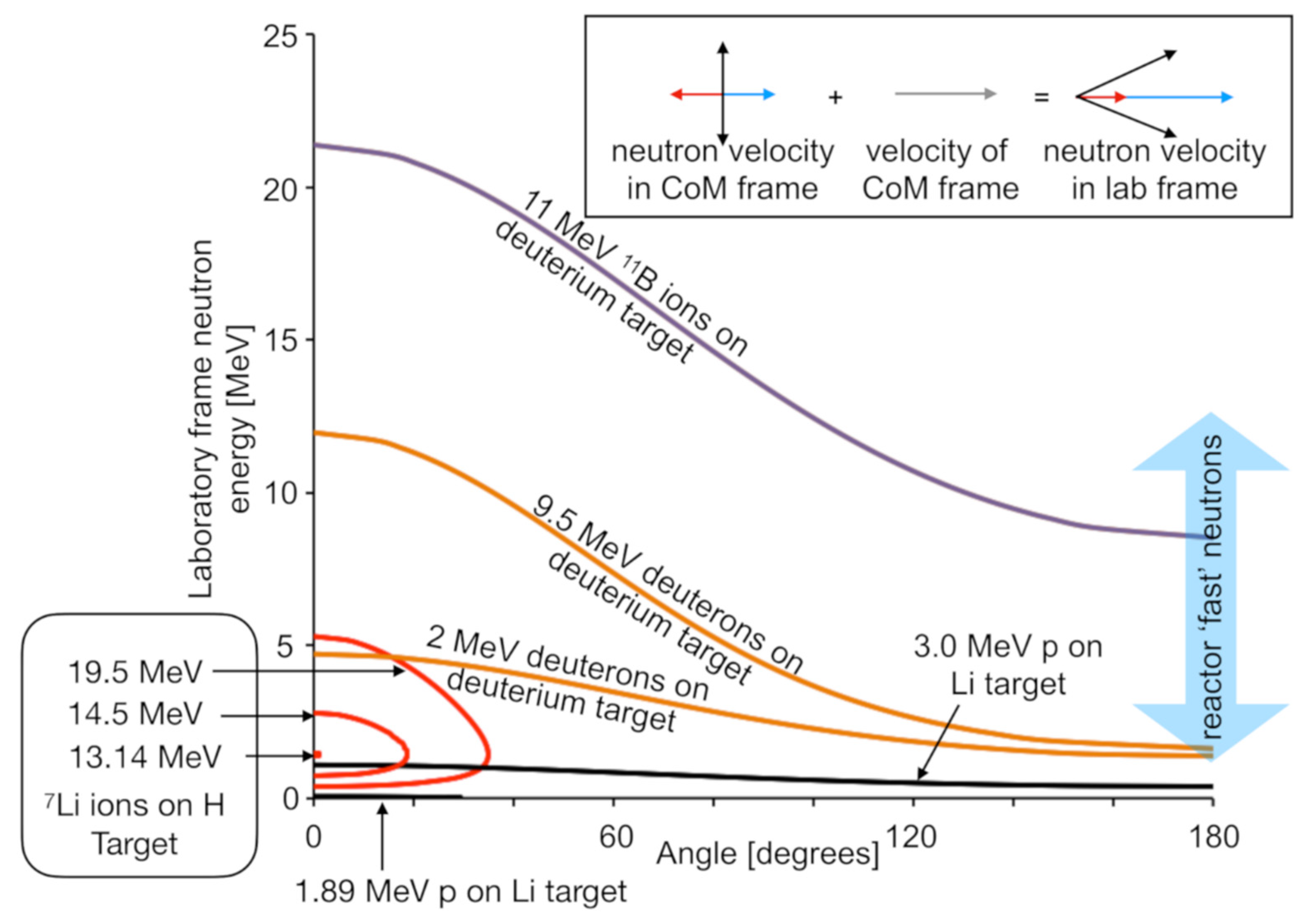
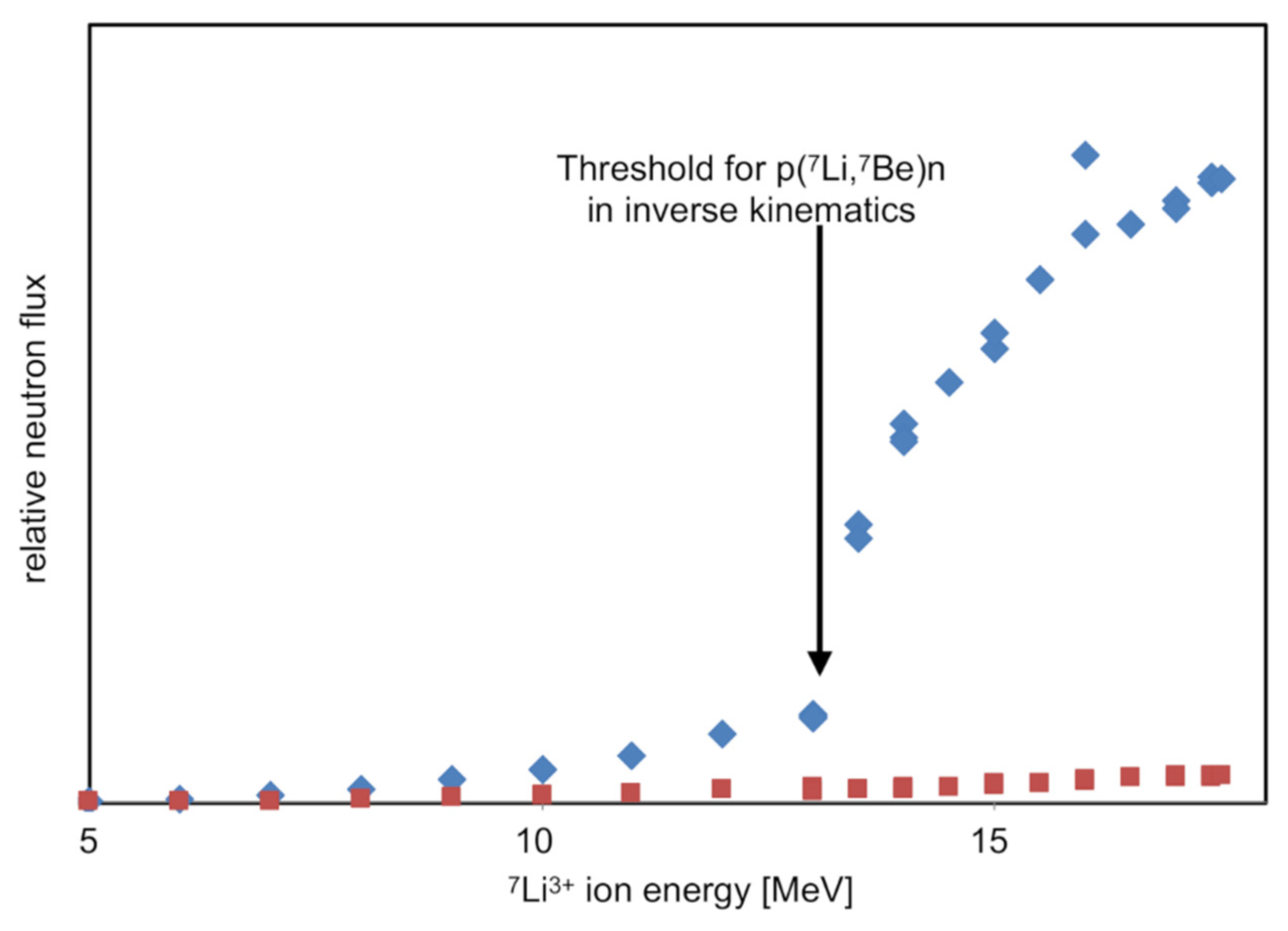
4.2. Variable-Energy Neutron Beams

Another recent activity has been the development of variable-energy neutron beams in a project nicknamed DANUBE (DAlton Neutron User BEams). Figure 14 illustrates examples of neutron production schemes available using DCF accelerators. All of these reactions rely on collision of two light nuclei (p, d, 7Li, 11B), so the neutron energy kinematics is highly dependent on the angle.
Building on a concept demonstrated previously [62], the 7Li inverse kinematics neutron generation scheme was implemented as it promises the highest fluxes by using the 7Li(p,n)7Be reaction. One of the attractive features of this scheme is that the projectile nucleus is more massive than the target nucleus, meaning that the center of mass of the collision system is moving forwards when viewed in the laboratory frame of reference. As a consequence, neutrons going into 4π in the collision frame all go into the forward direction in the laboratory frame. The closed contours are shown in Figure 14 for the impact of 7Li ions on hydrogen-rich targets. At high energies the 7Li ions produce neutrons with two distinct energies in the forward direction in the laboratory frame. The higher energy peak is due to forward ejection in the collision frame, which is further boosted in the laboratory frame by the motion of the center of mass of the collision pair, as illustrated by the blue arrows in the insert to Figure 14. The lower energy peak is due to backward-ejected neutrons in the collision frame, which results in slower neutrons in the laboratory frame, as illustrated by the red arrows in the insert.
As 7Li ions pass through a hydrogen-rich solid target, they will progressively slow down. However, they undergo negligible scattering. As they slow, they will produce a progressively more forward pointing beam of neutrons, i.e., the cone of neutrons in the center of mass frame shown in the Figure 14 insert will progressively close down. This process is illustrated by the three lines for 19.5, 14.5, and 13.18 MeV Li-ions. Below 13.18 MeV, neutrons are no longer produced as the collision is below the production threshold for the reaction. Hence, the prediction from kinematic simulations is that for 7Li ions impacting onto a thick hydrogen-rich target, no neutrons are expected below an energy of 13.18 MeV, after which an increasing yield of forward-directed neutrons will be expected along with a negligible yield of neutrons to the side of the ion beam axis. Results from the initial commissioning of our neutron beam, as shown in Figure 15, agree with these predictions.
The target used for this experiment was a simple static polymer. The below-threshold production of forward-directed neutrons and the small yield of sideward directed neutrons are probably due to interactions with impurities in the target. However, they are unimportant from the viewpoint of neutron-beam experiments.
One motivation for developing a high-energy neutron beam is to explore the radiation biology of neutron irradiated cells. This is motivated by the inevitable neutron burden created in proton therapy. High-energy protons, upon entering the patient, drive the reaction p + 16O → p + 15O + n, which can produce neutrons almost up to the energy of the initial proton beam (typ > 200 MeV). This reaction has a cross section of almost 100 mb for energies above 20 MeV [63], which, combined with the high density of oxygen (mostly through a patient’s water content), leads to approximately one high-energy neutron being created by every proton entering a patient during a proton therapy session. However, most of our current knowledge of neutron radiobiology pertains to boron neutron capture therapy, which involves much lower energy neutrons.
One of the major uses of proton therapy is the treatment of pediatric cancers; however, currently, there is insufficient radiobiology data to properly quantify the effect of the high-energy neutrons generated: “It is necessary to study RBE for tumor induction as a function of neutron dose, energy, dose-rate, tissue type, and size of the exposed patient” [64]. Simulations suggest that even using this simple static polymer target are sufficient to embark on a program of measurements of this kind, with dose rates of >0.01 Sv/min being available. More sophisticated targets, under development, would allow for 100 times higher neutron fluxes when high-energy neutron-driven chemistry relevant to reactor cooling systems becomes accessible.

5. Conclusions

The radiation facilities along with the associated sample management facilities at DCF have been shown to support a wide range of research related to radiation chemistry that is primarily aimed at supporting the UK’s nuclear industry. Results concerning material durability and suitability in harsh environments where radiation is present, and production of flammable gasses in particular, have been presented. Results from this research have stimulated the development of new sample-handling equipment ideal for longitudinal studies in radiation environments. This equipment has been described and will be instrumental in determining the dynamics of radiolytic gas generation. The greater understanding afforded by such studies will provide greater confidence in the safe operation of nuclear facilities.
Healthcare-related research opportunities available at such a facility have been illustrated using exemplar results that probe the mechanisms of radioprotection, and by the development of a neutron source that will enable the assessment of the late-cancer effects caused by the inevitable production of neutrons during proton therapy.
Taken together, the body of work presented here shows the benefit of concentrating a suite of radiation-research facilities together close to a nation’s nuclear industry as well as the potential for diversification beyond the mission implied by this co-location.

Author Contributions

Investigation, R.E., A.B., M.O., C.A., T.D., L.J., D.M., A.D., P.W., A.D.S., N.J.S.M., F.C., C.M.C., G.D.; writing—original draft preparation, L.L., F.C, A.D.S., S.d.M.S., R.E., A.B.; writing—review and editing, L.L.; supervision, L.L., F.C., S.M.P., A.B., J.H., R.O., H.S.; funding acquisition, F.C., S.M.P., L.L., A.B. All authors have read and agreed to the published version of the manuscript.

Funding

Irradiation of strippable coatings was funded by Sellafield Limited. Work on the irradiation of vitrified high-level waste and thoria were funded by separate EPSRC iCase studentship sponsored by the UK National Nuclear Laboratory and Sellafield Ltd. respectively. SMORES is being developed in part through a PhD studentship donated to the TRANSCEND consortium [https://transcendconsortium.org, accessed on 25 October 2021], by the UK’s Nuclear Decommissioning Authority, an iCase studentship provided funded by Sellafield Limited and the EPSRC, and an award from the TRANSCEND consortium’s active research fund.

Institutional Review Board Statement

Not applicable.

Informed Consent Statement

Not applicable.

Data Availability Statement

Please contact the corresponding author.

Acknowledgments

We thank Lian Murdoch for providing administrative support and Kevin Warren for providing a short history of the facility as well all of the staff and researchers, present and past, who have contributed to the Dalton Cumbrian Facility. Laura Leay thanks Maulik Patel and Paul Bingham for providing useful discussions about irradiation of glass and Alex Potts for his superlative use of many analytical techniques available at DCF to characterize cementitious materials. Ruth Edge thanks T. George Truscott for useful discussions on the carotenoid work. Simon Pimblott and Fred Currell thank Richard Clegg, Paul O’Brien, and Howard Sims for their vision initiating the DCF project, and Colin Bailey and Andrew Sherry for their efforts driving the project to fruition.

Conflicts of Interest

The authors declare no conflict of interest. The funders had no role in the design of the study; in the collection, analyses, or interpretation of data; in the writing of the manuscript, or in the decision to publish the results.

References

  1. Ayres, G.P. An Overview of Thirty Years of Operation of Calder Hall; British Nuclear Fuels Ltd.: Daresbury, UK, 1986; ISSN 03682595. [Google Scholar]
  2. World Nuclear Association Information Library. Nuclear Development in the United Kingdom Appendix 1. 2016. Available online: https://www.world-nuclear.org/information-library/country-profiles/countries-t-z/appendices/nuclear-development-in-the-united-kingdom.aspx (accessed on 25 October 2021).
  3. House of Lords Select Committee on Science and Technology. Report of Inquiry into Nuclear Research and Development (R&D) Capabilities in the UK. 2011. Available online: https://publications.parliament.uk/pa/ld201012/ldselect/ldsctech/221/22102.htm (accessed on 3 September 2021).
  4. UK Public General Acts. Energy Act 2004; Part 1: The Civil Nuclear Industry. 2004. Available online: https://www.legislation.gov.uk/ukpga/2004/20/contents (accessed on 3 September 2021).
  5. Nuclear Decommissioning Authority Corporate Report. Dalton Cumbrian Facility: 10 Years of Collaboration. 18 September 2017. Available online: https://www.gov.uk/government/publications/dalton-cumbrian-facility-celebrating-a-10-year-journey-to-success/dalton-cumbrian-facility-10-years-of-collaboration (accessed on 3 September 2021).
  6. UK Government Department for Business, Energy & Industrial Strategy; Nuclear Innovation and Research Office. UK Nuclear Fission R&D Catalogue: Facilities, Equipment and Capabilities, 1st ed.; Nuclear Innovation and Research Office: Warrington, UK, 2021.
  7. Leay, L.; Bower, W.; Horne, G.; Wady, P.; Baidak, A.; Pottinger, M.; Nancekievill, M.; Smith, A.; Watson, S.; Green, P.; et al. Development of irradiation capabilities to address the challenges of the nuclear industry. Nucl. Instrum. Methods Phys. Res. Sect. B Beam Interact. Mater. Atoms 2015, 343, 62–69. [Google Scholar] [CrossRef]
  8. Hauser, T.; Daniel, R.; Norton, G.; Schroeder, J. High current He injector for tandem accelerators. Nucl. Instrum. Methods Phys. Res. Sect. B Beam Interact. Mater. Atoms 2006, 249, 932–934. [Google Scholar] [CrossRef]
  9. Norton, G.A. Multi cathode SNICS ion source. In Proceedings of the 25th Symposium of North Eastern Accelerator Personnel, Santa Fe, NM, USA, 16–19 October 1991; Benson, J., Rowton, L., Tesmer, J., Darling, R., Eds.; World Scientific: Singapore, 1992; p. 29. [Google Scholar]
  10. Zinkle, S.; Was, G. Materials challenges in nuclear energy. Acta Mater. 2013, 61, 735–758. [Google Scholar] [CrossRef]
  11. Gilbert, M.; Dudarev, S.; Zheng, S.; Packer, L.; Sublet, J.-C. An integrated model for materials in a fusion power plant: Transmutation, gas production, and helium embrittlement under neutron irradiation. Nucl. Fusion 2012, 52. [Google Scholar] [CrossRef] [Green Version]
  12. Wiss, T.; Hiernaut, J.-P.; Roudil, D.; Colle, J.-Y.; Maugeri, E.; Talip, Z.; Janssen, A.; Rondinella, V.; Konings, R.J.; Matzke, H.-J.; et al. Evolution of spent nuclear fuel in dry storage conditions for millennia and beyond. J. Nucl. Mater. 2014, 451, 198–206. [Google Scholar] [CrossRef]
  13. Wady, P.; Draude, A.; Shubeita, S.; Smith, A.; Mason, N.; Pimblott, S.; Jimenez-Melero, E. Accelerated radiation damage test facility using a 5 MV tandem ion accelerator. Nucl. Instrum. Methods Phys. Res. Sect. A Accel. Spectrom. Detect. Assoc. Equip. 2016, 806, 109–116. [Google Scholar] [CrossRef]
  14. Ipatova, I.; Harrison, R.; Wady, P.; Shubeita, S.; Terentyev, D.; Donnelly, S.; Jimenez-Melero, E. Structural defect accumulation in tungsten and tungsten-5wt.% tantalum under incremental proton damage. J. Nucl. Mater. 2018, 501, 329–335. [Google Scholar] [CrossRef]
  15. Ipatova, I.; Wady, P.; Shubeita, S.; Barcellini, C.; Impagnatiello, A.; Jimenez-Melero, E. Radiation-induced void formation and ordering in Ta-W alloys. J. Nucl. Mater. 2017, 495, 343–350. [Google Scholar] [CrossRef]
  16. Fernández-Caballero, A.; Bousser, E.; Shubeita, S.; Wady, P.; Gu, Y.; Krishna, R.; Gorley, M.; Nguyen-Manh, D.; Mummery, P.; Pickering, E. High-dose ion irradiation damage in Fe28Ni28Mn26Cr18 characterised by TEM and depth-sensing nanoindentation. Nucl. Mater. Energy 2021, 28, 101028. [Google Scholar] [CrossRef]
  17. Impagnatiello, A.; Shubeita, S.; Wady, P.; Ipatova, I.; Dawson, H.; Barcellini, C.; Jimenez-Melero, E. Monolayer-thick TiO precipitation in V-4Cr-4Ti alloy induced by proton irradiation. Scr. Mater. 2017, 130, 174–177. [Google Scholar] [CrossRef] [Green Version]
  18. Spencer, R.P.; Patterson, E.A. Observations of fatigue crack behaviour in proton-irradiated 304 stainless steel. Fatigue Fract. Eng. Mater. Struct. 2019, 42, 2120–2132. [Google Scholar] [CrossRef]
  19. Thomas, R.; Lunt, D.; Atkinson, M.; da Fonseca, J.Q.; Preuss, M.; Barton, F.; O’Hanlon, J.; Frankel, P. Characterisation of irradiation enhanced strain localisation in a zirconium alloy. Materialia 2019, 5, 100248. [Google Scholar] [CrossRef]
  20. Bowden, D.; Ward, J.; Middleburgh, S.; Shubeita, S.D.M.; Zapata-Solvas, E.; Lapauw, T.; Vleugels, J.; Lambrinou, K.; Lee, W.; Preuss, M.; et al. The stability of irradiation-induced defects in Zr3AlC2, Nb4AlC3 and (Zr0.5, Ti0.5)3AlC2 MAX phase-based ceramics. Acta Mater. 2019, 183, 24–35. [Google Scholar] [CrossRef]
  21. Ward, J.; Bowden, D.; Stewart, D.; Barsoum, M.W.; Frankel, P.; Preuss, M. Influence of proton-irradiation temperature on the damage accumulation in Ti3SiC2 and Ti3AlC2. Scr. Mater. 2019, 165, 98–102. [Google Scholar] [CrossRef] [Green Version]
  22. Schofield, J.; Reiff, S.C.; Pimblott, S.; LaVerne, J.A. Radiolytic hydrogen generation at silicon carbide–water interfaces. J. Nucl. Mater. 2016, 469, 43–50. [Google Scholar] [CrossRef] [Green Version]
  23. Jones, L. The Radiation Chemistry of Gases at the Interface with Ceramic Oxides. Ph.D. Thesis, The University of Manchester, Manchester, UK, 2015. [Google Scholar]
  24. Leay, L.; Potts, A.; Donoclift, T. Geopolymers from fly ash and their gamma irradiation. Mater. Lett. 2018, 227, 240–242. [Google Scholar] [CrossRef]
  25. Potts, A.; Leay, L. Evidence for pore water composition controlling carbonate morphology in concrete and the further effect of gamma radiation. Constr. Build. Mater. 2021, 275, 122049. [Google Scholar] [CrossRef]
  26. Potts, A.; Butcher, E.; Cann, G.; Leay, L. Long term effects of gamma irradiation on in-service concrete structures. J. Nucl. Mater. 2021, 548, 152868. [Google Scholar] [CrossRef]
  27. Barr, L. Radiation Effects on Novel Polymeric Encapsulants. Ph.D. Thesis, The University of Manchester, Manchester, UK, 2015. [Google Scholar]
  28. Wady, P.; Wasilewski, A.; Brock, L.; Edge, R.; Baidak, A.; McBride, C.; Leay, L.; Griffiths, A.; Vallés, C. Effect of ionising radiation on the mechanical and structural properties of 3D printed plastics. Addit. Manuf. 2019, 31, 100907. [Google Scholar] [CrossRef]
  29. Horne, G. An Experimental and Computational Investigation into the Radiolysis of PUREX Solvent Systems. Ph.D. Thesis, The University of Manchester, Manchester, UK, 2015. [Google Scholar]
  30. Rautiyal, P.; Gupta, G.; Edge, R.; Leay, L.; Daubney, A.; Patel, M.; Jones, A.; Bingham, P. Gamma irradiation-induced defects in borosilicate glasses for high-level radioactive waste immobilisation. J. Nucl. Mater. 2020, 544, 152702. [Google Scholar] [CrossRef]
  31. Unisense H2 MICROSENSOR. Available online: http://www.unisense.com/H2/ (accessed on 30 September 2020).
  32. O’Leary, M.; Baidak, A.; Barnes, M.; Donoclift, T.; Emerson, C.; Figueira, C.; Fox, O.J.L.; Kleppe, A.; McCulloch, A.; Messer, D.M.; et al. First Observation of Radiolytic Bubble Formation in Unstirred Nano-powder Sludges and a Consistent Model Thereof. Sci. Rep. 2021, in press. [Google Scholar]
  33. Haschke, J.M.; Allen, T.H. Interactions of Plutonium Dioxide with Water and Oxygen-Hydrogen Mixtures; LA-13537-MS; Los Alamos National Laboratory: Los Alamos, NM, USA, 1999.
  34. Morales, L.A. Preliminary Report on the Recombination Rates of Hydrogen and Oxygen over Pure and Impure Plutonium Oxides; LA-UR-98-5022; Los Alamos National Laboratory: Los Alamos, NM, USA, 1998.
  35. Messer, D. Radiolytic Recombination of H2, O2 and N2 over PuO2 Surrogate Materials. Ph.D. Thesis, The University of Manchester, Manchester, UK, 2021. [Google Scholar]
  36. Short, R. Phase Separation and Crystallisation in UK HLW Vitrified Products. Proced. Mater. Sci. 2014, 7, 93–100. [Google Scholar] [CrossRef] [Green Version]
  37. Gin, S.; Abdelouas, A.; Criscenti, L.; Ebert, W.; Ferrand, K.; Geisler, T.; Harrison, M.; Inagaki, Y.; Mitsui, S.; Mueller, K.; et al. An international initiative on long-term behavior of high-level nuclear waste glass. Mater. Today 2013, 16, 243–248. [Google Scholar] [CrossRef]
  38. Ziegler, J.F.; Ziegler, M.; Biersack, J. SRIM—The stopping and range of ions in matter. Nucl. Instrum. Methods Phys. Res. Sect. B Beam Interact. Mater. Atoms 2010, 268, 1818–1823. [Google Scholar] [CrossRef] [Green Version]
  39. Eernisse, E.P. Compaction of ion-implanted fused silica. J. Appl. Phys. 1974, 45, 167–174. [Google Scholar] [CrossRef]
  40. Snoeks, E.; Weber, T.P.; Cacciato, A.; Polman, A. MeV ion irradiation-induced creation and relaxation of mechanical stress in silica. J. Appl. Phys. 1995, 78, 4723–4732. [Google Scholar] [CrossRef]
  41. Brongersma, M.L.; Snoeks, E.; van Dillen, T.; Polman, A. Origin of MeV ion irradiation-induced stress changes in SiO2. J. Appl. Phys. 2000, 88, 59–64. [Google Scholar] [CrossRef]
  42. Guo, X.; Gin, S.; Lei, P.; Yao, T.; Liu, H.; Schreiber, D.K.; Ngo, D.; Viswanathan, G.; Li, T.; Kim, S.H.; et al. Self-accelerated corrosion of nuclear waste forms at material interfaces. Nat. Mater. 2020, 19, 310–316. [Google Scholar] [CrossRef]
  43. Omenn, G.S.; Goodman, G.E.; Thornquist, M.D.; Balmes, J.R.; Cullen, M.; Glass, A.G.; Keogh, J.P.; Meyskens, F.L.; Valanis, B.G.; Williams, J.H.; et al. Effects of a Combination of Beta Carotene and Vitamin A on Lung Cancer and Cardiovascular Disease. N. Engl. J. Med. 1996, 334, 1150–1155. [Google Scholar] [CrossRef] [PubMed] [Green Version]
  44. Boehm, F.; Edge, R.; Truscott, T.G.; Witt, C. A dramatic effect of oxygen on protection of human cells against γ-radiation by lycopene. FEBS Lett. 2016, 590, 1086–1093. [Google Scholar] [CrossRef] [Green Version]
  45. Boehm, F.; Edge, R.; Truscott, T.G. Anti- and pro-oxidative mechanisms comparing the macular carotenoids zeaxanthin and lutein with other dietary carotenoids—A singlet oxygen, free-radical in vitro and ex vivo study. Photochem. Photobiol. Sci. 2020, 19, 1001–1008. [Google Scholar] [CrossRef] [PubMed]
  46. Bonnefont-Rousselot, D. Gamma radiolysis as a tool to study lipoprotein oxidation mechanisms. Biochimie 2004, 86, 903–911. [Google Scholar] [CrossRef] [PubMed]
  47. Buxton, G.V.; Greenstock, C.L.; Helman, W.P.; Ross, A.B. Critical Review of rate constants for reactions of hydrated electrons, hydrogen atoms and hydroxyl radicals (•OH/•O) in Aqueous Solution. J. Phys. Chem. Ref. Data 1988, 17, 513–886. [Google Scholar] [CrossRef] [Green Version]
  48. Donoclift, T.; Edge, R.; Unsworth, T.; Warren, K.; Jenkins, A.; Ostle, L. Radiation Tolerance Studies of Commercial Strippa ble Coatings and Fixatives used for Decontamination. In Proceedings of the Waste Management Conference, Phoenix, AZ, USA, 18–22 March 2018; p. 18642. [Google Scholar]
  49. Butarbutar, S.L.; Sanguanmith, S.; Meesungnoen, J.; Sunaryo, G.R.; Jay-Gerin, J.-P. Calculation of the Yields for the Primary Species Formed from the Radiolysis of Liquid Water by Fast Neutrons at Temperatures between 25–350 °C. Radiat. Res. 2014, 181, 659–665. [Google Scholar] [CrossRef] [PubMed] [Green Version]
  50. Spinks, J.W.T.; Woods, R.J. An Introduction to Radiation Chemistry, 3rd ed.; Wiley-Blackwell: Hoboken, NJ, USA, 1990. [Google Scholar]
  51. Ashmore, C.B.; Sims, H.E.; Tait, P.K.; Walters, W.S. The Measurement of Water Radiolysis Product Yields at High Temperature and Pressure; Progress Report AEAT—1278; AEA Technology: Didcot, UK, 1997. [Google Scholar]
  52. Sterniczuk, M.; Yakabuskie, P.A.; Wren, J.C.; Jacob, J.A.; Bartels, D.M. Low LET radiolysis escape yields for reducing radicals and H2 in pressurized high temperature water. Radiat. Phys. Chem. 2016, 121, 35–42. [Google Scholar] [CrossRef] [Green Version]
  53. Sanguanmith, S.; Muroya, Y.; Meesungnoen, J.; Lin, M.; Katsumura, Y.; Kohan, L.M.; Guzonas, D.; Stuart, C.; Jay-Gerin, J.-P. Low-linear energy transfer radiolysis of liquid water at elevated temperatures up to 350 °C: Monte-Carlo simulations. Chem. Phys. Lett. 2011, 508, 224–230. [Google Scholar] [CrossRef]
  54. Pimblott, S.M.; LaVerne, J.A. Effects of Track Structure on the Ion Radiolysis of the Fricke Dosimeter. J. Phys. Chem. A 2002, 106, 9420–9427. [Google Scholar] [CrossRef]
  55. Horne, G.P.; Donoclift, T.A.; Sims, H.E.; Orr, R.M.; Pimblott, S.M. Multi-Scale Modeling of the Gamma Radiolysis of Nitrate Solutions. J. Phys. Chem. B 2016, 120, 11781–11789. [Google Scholar] [CrossRef] [PubMed] [Green Version]
  56. Rishel, D.; Kammenzind, B. The role of gamma radiation on Zircaloy-4 corrosion. In Proceedings of the Zirconium in the Nuclear Industry: 18th International Symposium, Hilton Head, SC, USA, 15–19 May 2016; Comstock, R., Motta, A., Eds.; ASTM International: West Conshohocken, PA, USA, 2018; pp. 555–595. [Google Scholar] [CrossRef]
  57. Rishel, D.M.; Eklund, K.L.; Kammenzind, B.F.; Limbäck, M.; Kammenzind, B.; Dean, S.W. In situ EIS Measurements of Irradiated Zircaloy-4 Post-Transition Corrosion Kinetic Behavior. J. ASTM Int. 2008, 5, 326–359. [Google Scholar] [CrossRef]
  58. Chan, C.M. Project E1: Effect of gamma irradiation on Zirconium alloy corrosion. In Understanding Hydrogen Pickup Mechanism: MUZIC-3 Advanced Materials Characterization and Testing; EPRI Report No. 3002020953; Electric Power Research Institute, Inc.: Palo Alto, CA, USA, 2021; pp. 4-3–4-13. [Google Scholar]
  59. Polin, C.; Wardlow, N.; McQuaid, H.; Orr, P.; Villagomez-Bernabe, B.; Figueira, C.; Alexander, G.; Srigengan, S.; Brun, E.; Gilles, M.; et al. A novel experimental approach to investigate radiolysis processes in liquid samples using collimated radiation sources. Rev. Sci. Instrum. 2015, 86, 035106. [Google Scholar] [CrossRef] [PubMed] [Green Version]
  60. LaVerne, J.A.; Schuler, R.H. Radiation chemical studies with heavy ions: Oxidation of ferrous ion in the Fricke dosimeter. J. Phys. Chem. 1987, 91, 5770–5776. [Google Scholar] [CrossRef]
  61. Jonah, C.D.; Spinks, J.W.T.; Woods, R.J. Introduction to Radiation Chemistry. Radiat. Res. 1990, 124, 378. [Google Scholar] [CrossRef]
  62. Lebois, M.; Wilson, J.; Halipré, P.; Leniau, B.; Matea, I.; Oberstedt, A.; Verney, D. Development of a kinematically focused neutron source with the p(7Li,n)7Be inverse reaction. Nucl. Instrum. Methods Phys. Res. Sect. A Accel. Spectrom. Detect. Assoc. Equip. 2014, 735, 145–151. [Google Scholar] [CrossRef]
  63. JANIS—Renderer. 2021. Available online: https://www.oecd-nea.org/janisweb/book/protons/O16/MT28 (accessed on 29 August 2021).
  64. Eschneider, U.; Ehälg, R. The Impact of Neutrons in Clinical Proton Therapy. Front. Oncol. 2015, 5, 235. [Google Scholar] [CrossRef]
Figure 1. Irradiation chambers of equipment that supply ionizing photons. (a) The irradiation chamber of the 60Co gamma irradiator, measuring 20 cm wide by 25 cm deep by 27 cm high. The guide rods for the sources can be seen at the back of the chamber. One 19 mm rod is visible in the top of the chamber and another one is visible near the top of the left wall. (b) The X-ray irradiator sample chamber, measuring 41 cm wide by 88 cm deep and 58 cm high. The X-rays are applied from above so that the radiation spreads out into a cone travelling downwards. One sample port is located on the back wall in the bottom right of the image.
Applsci 11 11081 g001
Figure 2. Schematic overview (center) of DCF ion beam accelerators and current suite of experimental end-stations. Line 1 is a radiation hotcell for high-dose proton beam irradiations, with one chamber to house the materials damage vacuum chamber and a second adjacent cell for sample mounting, handling, and storage; Line 2 is for use with separate autoclaves, or to accommodate a user supplied end-station; Line 3 provides ion beam delivery for radiation chemistry experiments, flexibly mounted on an ex-vacuum optical table; Lines 5 and B are for in-vacuum radiation damage experiments using either heavy ions from the 5 MV tandem or light ions from the 2.5 MV accelerator, respectively; Line 7 is the dedicated ion beam analysis end-station.
Applsci 11 11081 g002
Figure 3. The Cormet™ Oy recirculation loop. (a) A photograph of the equipment which is about 1.8 m tall by 1.5 m wide. (b) A simplified schematic diagram of recirculation loop. Sensors labelled D[H2], D[O2] and EC monitor dissolved hydrogen (ppb), dissolved oxygen (ppb), and electrical conductivity, respectively.
Applsci 11 11081 g003aApplsci 11 11081 g003b
Figure 4. Autoclaves used with the recirculation loop. (a) Autoclave used for gamma radiolysis experiments. (b) Irradiation cell for ion beam experiments, where (1) is a closing nut, (2) ceramic washer, (3) metallic foil window; (4) water outlet line; (5) water inlet line; (6) temperature sensor.
Applsci 11 11081 g004
Figure 5. Results of radiolytic gas analysis experiments carried out on the particle accelerator using Unisense hydrogen probes to collect data. (a) The response of the hydrogen probe in mV during irradiations. Periods of irradiation are marked on the plot in red. (b) A linear trend is seen from experiments with fresh solutions of either magnesium hydroxide or potassium bromide.
Applsci 11 11081 g005
Figure 6. Gas radiolysis experiments using gamma radiation with analysis by gas chromatography. (a,b) H2 consumption in a 5:5:90 H2-O2-Ar atmosphere. (a) is the gas phase only and (b) is in the presence of CeO2 and ZrO2 [23]. (c,d) are from a 1:1:98 H2-O2-Ar atmosphere irradiated over 8 g of thoria and show the change in H2 and O2, respectively [35].
Applsci 11 11081 g006
Figure 7. A determination of volume change for different glass compositions that have been exposed to Ni ions beams of two different fluxes (ions cm−2 s−1). For each composition, one part of each sample was masked from the ion beam so that a step was produced by the change in volume.
Applsci 11 11081 g007
Figure 8. Absorbance of (a) astaxanthin in aqueous Triton-X 100 and (b) crocetin in water in the presence of sodium formate (generating O2•−) and absence of sodium formate (generating radicals including OH).
Applsci 11 11081 g008
Figure 9. FT-IR and Raman spectra from a selection of commercial strippable decontamination coatings that received an absorbed dose of 500 kGy from either gamma radiation or He ions. (a) FT-IR spectra from coating 1. (b) Raman spectra from coating 1. (c) FT-IR spectra from coating 3. (d) Raman spectra from coating 3. (e) FT-IR spectra from coating 8. (f) Raman spectra from coating 8.
Applsci 11 11081 g009aApplsci 11 11081 g009b
Figure 10. (a) Determined G-value of molecular hydrogen as a function of the fluid flow rate (kg/h) through the autoclave upon gamma irradiation of deaerated 1 mM KBr solution. (b) Radiation chemical yield of H2 from a scavenger system containing 1 mM NO3, 1 mM Br, and 10 mM CHO2 under deaerated conditions and room temperature irradiated with a proton beam as a function of particle energy. All irradiations were performed using 10 nA current with exposures lasting for 15 min.
Applsci 11 11081 g010
Figure 11. Photo-voltage response of pre-transition and post-transition Zircaloy-4 under gamma irradiation at 150 °C.
Applsci 11 11081 g011
Figure 12. Illustration of a particular configuration of SMORES components to facilitate four parallel studies involving the dynamics of gas and liquid phase radiolysis in the presence of metal oxides. The grey semi-transparent cube illustrates the approximate volume of the DCF 60Co irradiator. The 60Co rods are located at the back of the irradiator and the assembly that sits outside of the grey irradiator volume makes use of sample ports in the irradiator shielding.
Applsci 11 11081 g012
Figure 13. A new sample handing system developed for ion beam experiments. (a) Schematic illustration of the spinning wine glass sample holder and syringe pumps configured to support irradiation of thin samples. (b) The amount of ferric ions produced by irradiation by 5 MeV protons. The dashed line shows the early high ferric ion production at 0.64 µmolJ−1 the dotted line showing the later slower production at 0.275 µmolJ−1.
Applsci 11 11081 g013
Figure 14. Simulations of examples of the kinematics available for neutron production in thin targets using the accelerators available at DCF. Each line is labelled with the collision conditions pertaining to the neutron production. The x-axis shows the angle at which neutrons would be ejected with respect to the beam axis. The corresponding neutron energy is indicated on the y-axis. Towards the bottom left of this figure, several of the lines, corresponding to the inverse kinematic 7Li(p,n)7Be reaction, are shown. These lines show two values of neutron energy, although they do not cover the full angular range. This is because the reaction can produce two neutron energies in the lab frame, but it is impossible to produce neutrons at large angle, i.e., these collisions result in a directed beam. The insert illustrates the kinematics giving rise to this effect and is explained in the main text.
Applsci 11 11081 g014
Figure 15. Results of the first commissioning experiments of the DANUBE neutron beam. The blue points show the current-normalized relative yield of neutrons in the forward direction, while the red points show the same yield but for 90° from the beam axis.
Applsci 11 11081 g015
Table 1. Three glass compositions, in wt%, of relevance to the nuclear industry were exposed to a 14 MeV ion beam. Vitreous silica was also used. The penetration depth of the ion beam, as calculated by SRIM-2013 [38], and used in the step height calculations, is also provided.
ComponentMWCa/ZnISG
SiO261.7556.1056.18
B2O321.8821.5117.34
Na2O11.0511.4812.17
Li2O5.332.92-
ZnO-6.03-
CaO-1.944.98
ZrO2--3.27
Penetration Depth (μm)5.686.406.75
Publisher’s Note: MDPI stays neutral with regard to jurisdictional claims in published maps and institutional affiliations.

