Article

A Tunable Metamaterial Joint for Mechanical Shock Applications Inspired by Carbon Nanotubes

by
Georgios I. Giannopoulos
1,* and
Stylianos K. Georgantzinos
2
1
Department of Mechanical Engineering, School of Engineering, University of Peloponnese, 1 Megalou Alexandrou Street, 26334 Patras, Greece
2
Department of Aerospace Science and Technology, National and Kapodistrian University of Athens, 34400 Psachna, Greece
*
Author to whom correspondence should be addressed.
Appl. Sci. 2021, 11(23), 11139; https://doi.org/10.3390/app112311139
Submission received: 3 November 2021 / Revised: 19 November 2021 / Accepted: 22 November 2021 / Published: 24 November 2021
(This article belongs to the Special Issue Impact-Resistant Composites: Design and Damage Control)

Abstract

:
The significant developments of additive manufacturing and especially 3D-printing technologies have broadened the application field of metamaterials. The present study aims at establishing the main design parameters of a novel 3D-printed polymer-based joint. The proposed joint can efficiently absorb impact energy, relieving the material components from extensive plastic deformations. The design of the machine element is inspired by the molecular structure of carbon nanotubes and appropriately adjusted in such a way that it has the ability to partially transform translational motion to rotational motion and, thus, provide axial structural protection from compressive shocks. The utilized material is a photosensitive resin that is typically utilized in 3D manufacturing processes. Experiments are utilized to characterize the mechanical performance of the raw material as well as the static compressive behavior of the joint. Finally, finite element simulations are performed to test the developed design under impact loadings characterized by different frequencies. The damping capabilities of the metamaterial-based joint are revealed and discussed.

1. Introduction

In recent decades, materials science has moved forward to modern areas that focus on the development of advanced nanomaterials [1] and metamaterials [2] for efficient use in devices and systems as well as novel engineering and industrial applications.
With the development of nanotechnology, the mechanical behavior of a variety of organic and inorganic nanomaterials was thoroughly investigated [3] with respect to their nanosizes, forms of crystallinity, dimensionalities, chemical functionalization, atomistic periodicities, and the natures of their molecular structures using experimental [4] and theoretical methods [5]. Today, there is a lot of evidence and information that permits the efficient design of nanomaterials with controllable, tuned mechanical responses [6,7]. Special attention has been given to the mechanical modeling and characterization of graphene-like molecules, due to their exceptional mechanical properties [8] as well as their ability to adapt to various mechanical requirements and working conditions by simply altering their size, shape, crystallinity, or functionalization [7,9]. Their unique mechanical and physical properties are due to their unique carbon hexagonal lattice structure [10]. The hexagonal atomistic structure of graphene and carbon nanotubes (CNTs), due to its strength and deformation abilities, has attracted interest for applications not only at the nanoscale but at the microscale as well. The idea of imitating the structural characteristics of nanomaterials in larger components via the introduction of relevant metamaterials with hexagonal or honeycomb lattice patterns [11,12] seems to produce impressive results in demanding engineering fields such as automotive and aerospace engineering. Discrete design schemes in metamaterials may provide a variety of enhanced properties such as high strength, stiffness, and fracture toughness, and light weight [13].
Nevertheless, to realize such a capability, i.e., imitate the molecular structure of nanomaterials such as graphene and CNTs at natural scales, the adoption of special manufacturing technologies is required. The production of material components that are inspired by the structural characteristics of nanomaterials would be a very difficult task if typical manufacturing processes are utilized, considering the significantly discrete natures of their geometries. Providentially, at present, the difficulty in producing complex three-dimensional (3D) hexagonal-like geometries at a micro-level may be overcome by the utilization of modern additive manufacturing procedures such as 3D printing or laser sintering [14,15]. In addition, it is now well understood that the complete mechanical behavior of wireframe-like metamaterials can be easily and accurately predicted through the use of simple finite element (FE) models, and even by using two-noded-line finite elements [15]. Generally, the FE method (FEM) may be seen as the ultimate method for accomplishing ideal metamaterial designs [15,16,17], without wasting time, material, equipment, and human resources, in order to conduct complex parametric experimental studies. The recent additive manufacturing breakthroughs and the well-established FEM simulation tools offer new opportunities for discoveries in structural engineering.
One of the main advantages of metamaterials is the fact that their mechanical performance and physical properties may be tuned by modifying their microstructural geometries [18]. Small structural modifications in metamaterial-based components may allow the efficient adjustment of several targeting properties such as strength, stiffness, and plasticity. Impressively, by using clever microstructural configurations, the final performance of the 3D-printed metamaterial may be considerably uncoupled from the fundamental characteristics of the basic raw material. For example, using appropriate microstructural patterns and architectures, special metamaterial-based components may be created, which, for example, are capable of transforming an axial deformation response to a twisting one [19], or a brittle behavior to a ductile one [20].
As there is a great demand for new protective solutions under vibration or shock types of loadings, special attention is paid to the development of metamaterials that are capable of absorbing energy and present excellent damping properties [21]. In an interesting study, Chen et al. [22] synthetically investigated a series of 3D double-arrow-head auxetic structures made from a carbon fiber-reinforced polymer. The damping performance of the specimens was characterized by compressive loading-unloading tests and sine sweep frequency experiments. In the theoretical framework, Qiao and Chen [23] performed systematical simulations of uniform functionally graded double arrowhead honeycombs subject to different impact velocities to reveal their improved energy absorption capacity under high-velocity impacts. Ma et al. [24] focused on both the experimental and numerical investigation of carbon fiber composite auxetic double-arrow corrugated sandwich panels with enhanced vibration damping. Regarding the macro-scale, Miniaci et al. [25] studied large-scale mechanical metamaterials offering protection against seismic waves of specific frequency ranges. Furthermore, they proposed optimal designs via the exploration of various metamaterial formations by combining phononic crystals and locally resonant structures. Similarly, Van Belle et al. [26] used a unit cell method including damping to investigate the complex dispersion curves of a locally resonant metamaterial design. The outcome was validated through corresponding experimental measurements, while it was illustrated that locally resonant metamaterials show great potential for use in noise and vibration applications. Several research efforts were made in the field of impact-resistant metamaterials as well. Characteristically, Rebelo et al. [27] investigated the nonlinear response of 3D-printed polylactic acid (PLA) honeycomb structures to analyze their energy absorption capabilities when utilized as the core component of sacrificial claddings. Similarly, Santos et al. [28] studied the low-velocity impact response of 3D-printed layered structures made of thermoplastic materials such as PLA and polyethylene terephthalate glycol (PETg). They showed that the use of honeycomb and auxetic structures as a core may lead to the development of advanced sacrificial shells for impact protection. Finally, after conducting comprehensive research based on both experimental and FE predictions, Chen et al. [29] provided new designs of a new class of shell lattice, stretching-dominated, mechanical metamaterial that can absorb high-energy shocks by simultaneously retaining a low density.
Despite the fact that there have been numerous attempts to characterize metamaterials of various configurations and base materials, their capabilities when used as machine elements or components have not been tested to the same extent. In the present study, a new design of a metamaterial-based mechanical joint is proposed, which is capable of absorbing energy under impact or vibration loadings. In an effort to create a metamaterial component that is ultra-stiff, ultra-strong, and possesses high specific energy absorption at low relative density, the proposed architecture of the joint is inspired by the hexagonal lattice of CNTs, while the used material is a polyurethane-based ultraviolet (UV) sensitive resin of a high inherent material damping. The cylindrical and periodical hexagonal lattices of the load-carrying components of the joint are formed in such a way as to enable the partial conversion of compressive deformations to rotational motion of a cylindrical mass. This inertia disk is inserted and attached between two opposing triple-wall CNT-like tubular wireframes. In this way, the tubular walls of the joint, which axially carry the impact loads, remain structurally protected since they receive less plastic energy. Different FE analyses are carried out to predict the static and dynamic structural behavior of the joint at room temperature under compressive and impact loadings, respectively. Additive manufacturing is used to create specimens for the experimental characterization of the raw material itself under axial loadings as well as the creation of prototypes of the proposed mechanical joint to validate its numerically predicted static mechanical response.
To summarize, a new design of a mechanical joint made of a polymeric metamaterial is proposed. The specific machine element differs from the standard ones due to its discrete structural architecture. Its main advantage is the fact that it combines specific attributes such as low density and high strength while being efficient in absorbing axial stresses via the release of rotational kinetic energy. The proposed machine element, which may be successfully manufactured via additive manufacturing techniques, could be effectively used for the improvement of the damping capability of machine tools [30].

2. Design and Microstructure of the Joint

The microstructure of the proposed metamaterial-based joint is illustrated in Figure 1. The design of the mechanical joint is adapted to the specific frequency range and size of the impact loadings that are investigated here. The joint is fully composed of a polymeric material, i.e., a UV-curable resin, which is frequently used in stereolithography-based 3D printing techniques.
The basic load-carrying component of the joint is a triple-wall tubular wireframe, shown in Figure 2, that is inspired by the nanostructure of the well-known CNTs. The triple-wall wireframe is—in all places—characterized by a wire diameter d = 1 mm , while it consists of three concentric cylindrical hexagonal lattices. The architecture of the central tubular wireframe is analogous to the atomistic discrete geometry of the single-wall CNT (SWCNT) of the armchair type ( n , n ) = ( 10 , 10 ) . For the purpose of the present research, the mean radius of the central tubular wireframe is chosen to be equal to R c = 20 mm , while its nodal positions may be defined in a global Cartesian coordinate system ( x , y , z ) using the following equation [31]:
( x c , y c , z c ) = ( R c cos ( X R c ) , r c sin ( X R c ) , Y )
where ( X , Y ) are the corresponding in-plane nodal coordinates for a two-dimensional (2d) graphene-like honeycomb lattice lying in the x y plane, defined by the following hexagonal side length [31]:
l hex = 2 π 3 n R c
The required key attribute of the developed joint is its ability to transform an amount of the axial compressive strains into torsional ones, providing structural protection in the impact loading direction (vertical z-axis). To provide such a property, two inclined, parallel, wire reinforcements are added in each hexagonal microstructure, as Figure 2 illustrates.
For the ( 10 , 10 ) SWCNT-based microstructure, these wire additions lead to the creation of twenty right-handed helixes (spirals) of a helix angle of about θ c = 30 ο [31]. Consequently, the developed angular structural inhomogeneity along the longitudinal axis of the tubular wireframe results in the appearance of twisting phenomena under axial tension or compression. The total length of the triple-wall wireframe, which may be measured parallel to the axis of the helixes, is chosen in such a way so that one complete helix turn is obtained, i.e.,:
L = 2 π R c tan θ c
The inner and outer wireframes are chosen to have a similar tubular hexagonal structure as the central one, and they are designed to have a radius of R i = 0.75 R c and R o = 1.25 R c , respectively, while their nodal positions are defined, respectively, by:
( x i , y i , z i ) = ( 0.75 x c , 0.75 y c , z c )
( x o , y o , z o ) = ( 1.25 x c , 1.25 y c , z c )
To assure that the triple-wall wireframe presents transverse structural coherence, a suitable interconnection should be generated between the three concentric tubular lattices. Therefore, as Figure 2 illustrates, the nodes of the central wireframe are radially connected with the nodes of the inner and outer wireframes lying in the same horizontal planes via the introduction of straight wire links that have a length of l link = 0.25 r c .
The proposed joint, as Figure 1 depicts, also contains three horizontal flat circular layers, i.e., a bottom and upper face layer both having a radius R b = R o = 1.25 R c and thickness h b = h = 2 mm , an upper face layer of radius R u = R o and thickness h u = h , and, finally, a middle inertia disk referred to hereafter as a “flywheel” of radius R m = 2 R o and thickness h m = 2 h . The bottom layer has the role of the foundation (fixed) and is connected with the flywheel through the previously presented triple-wall wireframe with the right-handed helical elements. On the other hand, the upper layer is the receiver of the shock loading (target) and is connected with the flywheel with the mirrored version of the triple-wall wireframe, which has left-handed helical reinforcements. This kind of metamaterial-based configuration, consisting of the two opposing triple-wall wireframes, permits the partial conversion of the vertical movement of the upper layer to the axial rotation of the flywheel.

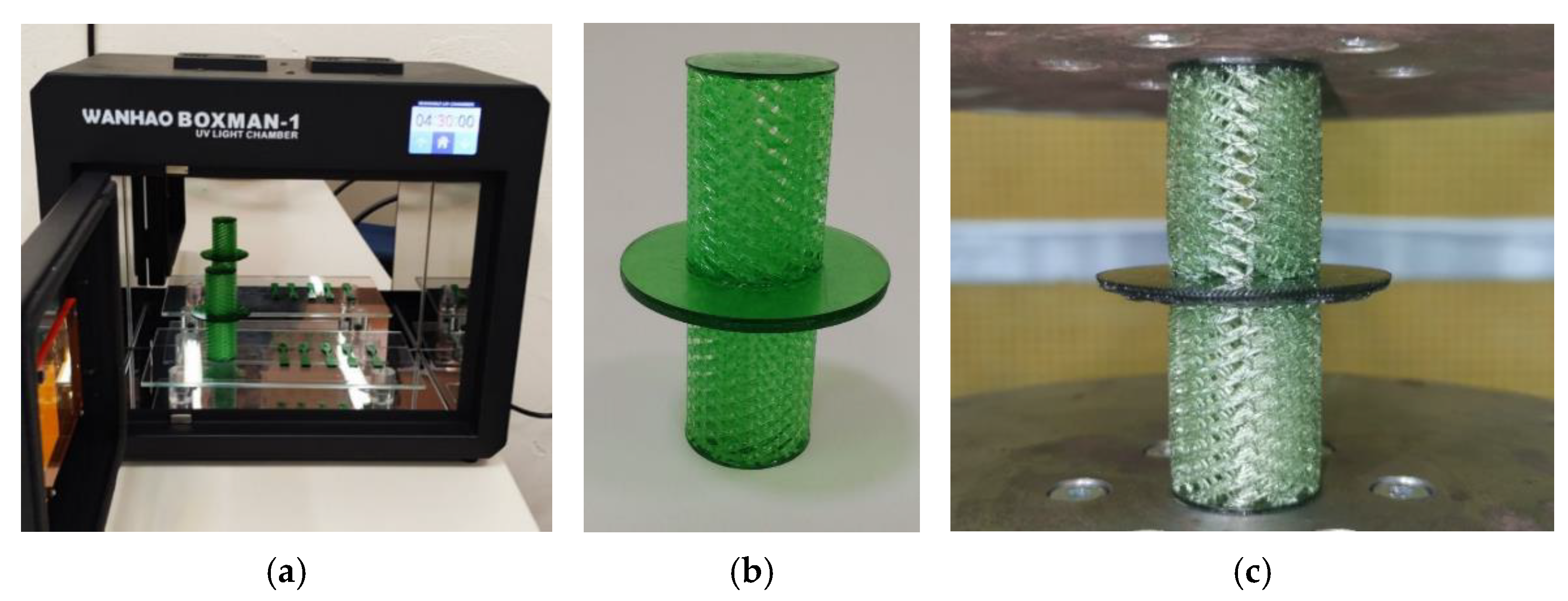
3. Experimental Characterization of the UV Resin After-Curing Mechanical Behavior

For the purpose of the current research, a photosensitive resin was utilized as a raw material. The final parts were printed by using a 3D printer with Liquid Crystal Display (LCD) irradiation [32]. The LCD-based printing is a method of creating 3D objects using a light-emitting device and, thus, is very similar to the well-known stereolithography (SLA) method [33]. SLA aims at the curing of a specific target point of a layer of the component to be printed. The curing is achieved through the utilization of a focused laser beam, the size of which affects the resolution of the printed product [33]. Similarly, the LCD-based additive manufacturing process uses UV light to cure the resin raw material. However, according to the working principle of the photosensitive 3D printer with LCD light irradiation, specific image signals are provided by a computer program and displayed on a screen driving circuit. During the process, transparent zones appear on the screen before the initiation of the irradiation. During irradiation, the UV lights transmit through the LCD screen to form the part cross-section. A transparent film is set at the bottom of a liquid tank, which is placed on the surface of the liquid crystal screen. The UV light is radiated by the LCD screen to the photosensitive liquid resin via the transparent film. Thus, the resin is polymerized by the curing reaction and then solidified.
The UV resin used in this study was provided by “Anycubic” and is a mixture of monomers, acrylates, and polymerization initiators. The limited information provided by the supplier refers to a resin that consists of 30–60% polyurethane acrylate, 10–40% acrylate monomer, and 5–10% photo-initiator. The specific resin selection was made only for testing and validation reasons. However, it was preferred over other similar materials due to its good specific strength and damping properties. Thus, in the future, according to the contribution and findings of the present study, a more appropriate polymeric medium could be adopted, which could be characterized by even more effectual mechanical properties, providing an improved version of the joint. Various specimens were prepared and printed using the “Creality LD-002H UV Resin 3D Printer”, according to the ASTM standards for the testing of the tensile properties of plastics. Figure 3a–c presents the configuration of the used 3D printer, five additively manufactured specimens, and the utilized tensile testing equipment, respectively. In addition, Table 1 summarizes some basic specifications regarding the adopted 3D-printing machine and process parameters for manufacturing the standardized specimens.
Three different groups of five specimens were prepared, corresponding to an after-print curing time of 1.5, 3.0, and 4.5 h. The measurements proved that the extended curing process leads to a higher mechanical performance regarding both the stiffness and tensile strength of the 3D-printed specimens. Consequently, the higher fracture toughness was observed for 4.5 h, and the obtained stress–strain curves for this case, using a small strain rate of about 1 mm/min at room temperature, are given in Figure 4. For this case, an average stress–strain behavior was extracted, denoted in Figure 4 with a red dotted line, to be inserted in the FEM-based models for the numerical simulation of the proposed joint. The specific average stress–strain behavior was expressed by an elastic modulus and a tensile strength of about E = 842 MPa and σ UTS = 76 MPa , respectively. The fracture occurred at a strain of about ε fr = 15 % after a distinct strain-hardening region.

4. Results

4.1. Fundamental Equations and Numerical Process

It is convenient to develop the finite element model according to a global Cartesian coordinate system ( x , y , z ). Based on the aforementioned explained geometry of the joint, shown in Figure 1, a variety of FE analyses may be performed [34]. The aim is the development of an accurate and simultaneously computationally efficient FE model to simulate the mechanical behavior of the joint at room temperature. An elastoplastic constitutive model is generally required for representing the quasi-static mechanical behavior of the metamaterial, while an implicit time integration scheme should be adopted to numerically predict its dynamic response. Generally, the equation of motion for the joint may be expressed in a matricial form in the global coordinate system by applying the conventional displacement formulation. After discretizing the joint with finite elements, assigning the material attributes, and applying the boundary conditions, the dynamic elemental equation becomes:
M x ¨ + C x ˙ + K x = F
where M , C , and K is the assembled mass, damping, and stiffness matrix of the meshed problem domain, x is a vector containing all nodal translations and rotations, while F is the force vector representing the applied time-dependent load. The dot denotes integration over time t .
The above system of equations is solved in an incremental-iterative manner to treat the inherent material nonlinearity of the polymeric material [34]. On the other hand, when the elastic stability analysis of the joint is to be carried out, a different numerical treatment is required. The problem of linear structural stability may be simulated by applying a reference level of loading F ref to the system by ignoring the plasticity of the 3D-printed material. Then, a linear elastic static analysis must be performed, using Equation (6) with x ˙ = x ¨ = 0 , to estimate the load required to form the geometric stiffness matrix K G [34]. The stability load is finally calculated by solving the eigenvalue equation:
[ K λ K G ] x e = 0
where λ is the multiplier to the reference load, while the vector x e denotes the eigenvector corresponding to the eigenvalue.
The eigenvalue problem may be solved by adopting a standard solution algorithm such as the Lanczos method [33]. The critical load F cr , which leads to the principal stability loss of the joint, is the most important and it is associated with the lowest eigenvalue λ cr according to the equation:
F cr = λ cr F ref

4.2. Mesh, Material Properties, and Boundary Conditions

The triple-wall wireframe was modeled by using exclusively 3D, two-noded, linear, straight, thick beam elements, which included shearing deformations and had six degrees of freedom (DoFs) at each node, i.e., three translations and three rotations. Everywhere in the model, two beam elements were utilized for the division of each straight wireline, while a circular cross-section of a diameter d = 1 mm was assumed for each element. Specifically, 7080, 4800, and 3040 beam elements were utilized for the discretization of the sides of all hexagons, the inclined reinforcements, and the inter-wall radial links, respectively. The lower face, the middle flywheel, and the upper face were modeled by using appropriate 3D, four-noded, linear, quadrilateral, thick shell elements with six DoFs per node. As a result, the corresponding circular areas in the planes z = 0 , z = L , and z = 2 L were discretized by using 527, 767, and 527 shell elements of an equivalent thickness of 2 mm, 4 mm, and 2 mm, respectively. A representative mesh of the adopted finite element model is illustrated in Figure 5.
To express the elastoplastic mechanical behavior of all finite elements, a Von Mises potential material model was assumed [34] according to the average experimental stress–strain curve shown in Figure 4. The utilized Von Mises stress potential function includes a nonlinear hardening behavior approximated by using a series of straight-line segments. Following the present experimental evidence, the almost isotropic elastic response of the 3D-printed material may be computationally described by an elastic modulus and Poisson’s ratio of E = 842 MPa and ν = 0.35 , respectively. The damping properties of the investigated material were of high importance for the accurate numerical prediction of the joint performance under mechanical shock conditions. To simulate the energy dissipation characteristics of the 3D-printed polymeric material, a Rayleigh damping model was introduced [35]. According to the Rayleigh model, the damping matrix of the system is expressed as a linear combination of the mass and stiffness matrix, i.e.,
C = a M + b K
For the requirements of the present work, a mass and stiffness constant of a = 3 . 673 and β = 2 . 446 × 10 3 were adopted, respectively. The specific values were calculated by using experimental evidence regarding the loss factor ζ , also known as tan δ , of the 3D-printed material at a frequency level f 1 = 1 Hz . The loss factor of the Anycubic UV resin at such a frequency was estimated at ζ 1 = 0.3 [32,36,37]. Assuming that at a higher frequency of f 2 = 50 Hz the material typically exhibits a 30% increase in its loss factor [36,37], i.e., ζ 2 = 1.3 ζ 1 , one may estimate the alpha and beta constants required in the Rayleigh damping model via the following equations:
α = 4 π f 1 f 2 ζ 1 f 2 ζ 2 f 1 f 2 2 f 1 2
β = 1 π ζ 2 f 2 ζ 1 f 1 f 2 2 f 1 2
It should be mentioned that, according to the approach developed here, the damping Rayleigh model was not holistically applied for the entire structure, a fact that would pre-require a complete modal analysis of the joint to determine its natural frequencies. Here, the experimental loss factor of the pure raw material was implemented for two different frequencies, i.e., 1 and 50 Hz, which were representative of the investigated frequency range. Then, based on these two data points, the energy dissipation of the system was indirectly approximated by assigning the internal friction of the solidified resin (as a separate material property), which was reasonably approximated via a Rayleigh-like damping ratio curve within the tested frequency domain. Such, a simulation capability [34] is not offered by all the common commercial FEM codes.
The mass density of the material was taken to be equal to ρ = 1184 kg / m 3 in accordance with the specifications provided by the supplier as well as the present experimental observations.
In all conducted numerical tests, all DoFs of the bottom face were kept fixed while only the vertical translational DoF of the upper face was kept free to allow the action of axial compressive static or dynamic loadings.

5. Evaluation and Characterization of the Compressive Behavior of the Joint

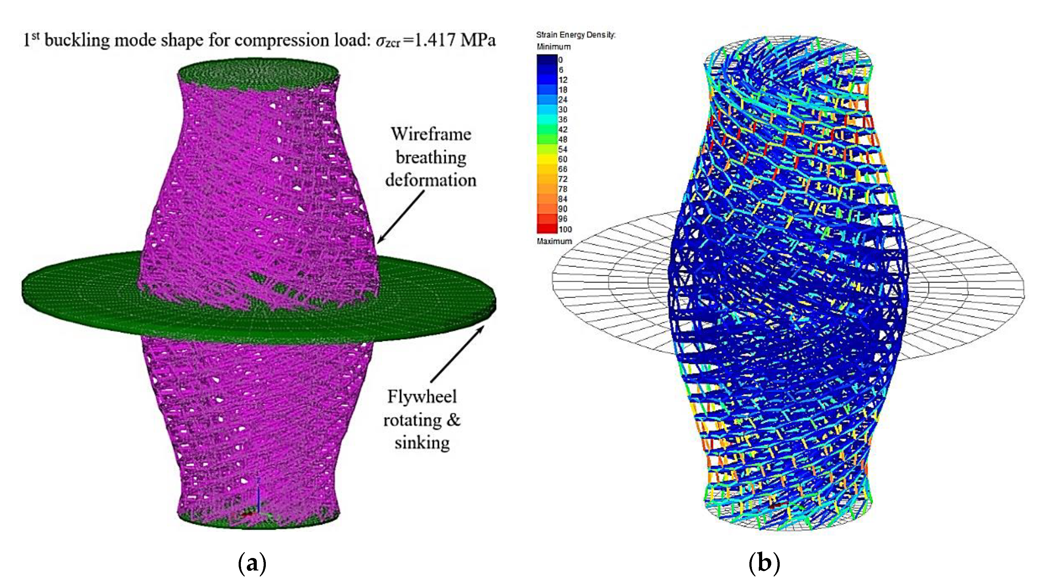
5.1. Linear Elastic Buckling Analysis

In order to investigate the full elastoplastic mechanical response of the joint under a stationary compressive load, a numerical test regarding its linear stability was carried out beforehand. For this reason, the material was assumed to be linear elastic, while a reference level of compressive static stress equal to σ z = 1 MPa was applied on the upper face of the joint. The computed first and critical buckling mode shapes are depicted in Figure 6.
It may be observed that the first buckling mode shape was associated with intensive twisting and circumferential-breathing deformations of the wireframe walls accompanied by significant torsion of the flywheel, also leading to the loss of its horizontal position. The lowest eigenvalue was found to be λ cr = 1.417 resulting in a critical compression stress load of σ z cr = λ cr σ z = 1.417 MPa . Hence, all the tests conducted in the following are related to maximum compressive loads significantly lower than 1.4 MPa.

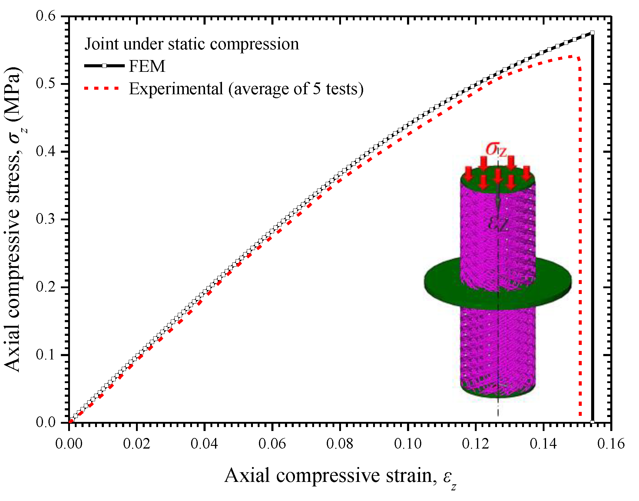
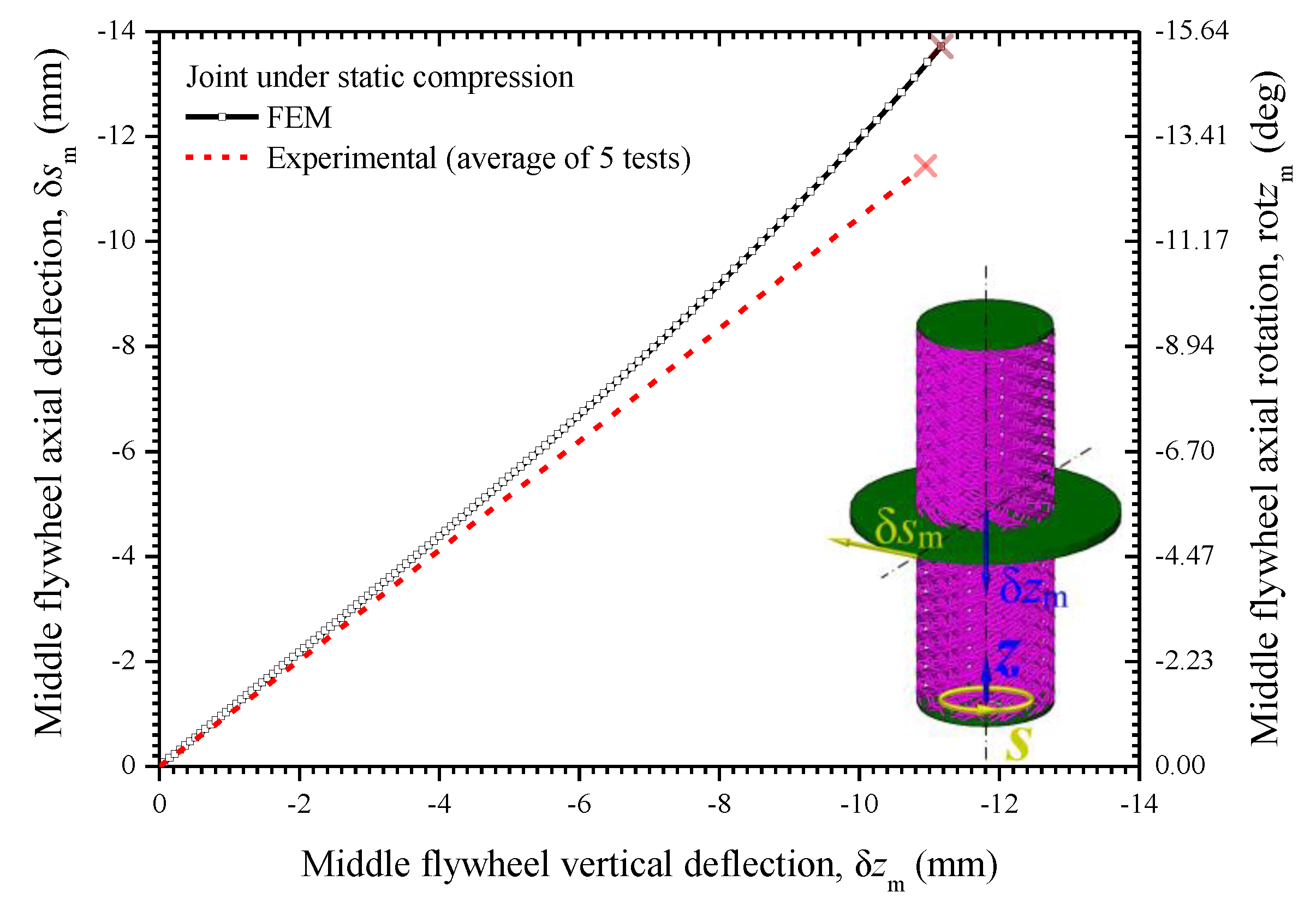
5.2. Static Elastoplastic Analysis

In this section, the full elastoplastic compressive behavior of the joint is under investigation. Here, a static compressive load was considered to act at the upper circular lamina of the joint. The static load was applied incrementally in order to treat the inherent material non-linearity, while a Newton–Raphson iterative algorithm, controlled by the residual force and incremental displacement norms, was introduced between subsequent increments to obtain equilibrium and convergent solutions. The variation of the axial compressive stress σ z with respect to the axial strain ε z of the joint is presented in Figure 7. Linear elastic behavior was achieved for strains up to 5%. Then, mild strain-hardening regions were observed until the fracture.
The compressive stress–strain behavior of the joint was also estimated by developing and using an experimental simplified setup, consisting of a medium-size tensile machine and a digital camera, for capturing both the axial translational and twisting deformations of five 3D-printed prototypes during their quasi-static compression. It should be noticed that the five prototypes of the joint had additionally been cured for 4.5 h after being manufactured by the LCD 3D printer. Figure 8a–c present illustrations regarding the curing process of a joint prototype, the undeformed configuration of a printed joint, and the compressed state of a similar part within the testing machine.
Good agreement between the theoretical and average measured data may be observed in Figure 7. Some differences were perhaps due to the small structural imperfections in the final printed parts caused by the technological limitations of the utilized printing machine and technique. Furthermore, as Figure 9a illustrates, the failure initiation of the joint occurred in a hexagon wire side, located at both the upper and bottom inner-wall wireframes. Note that the specific pre-failure deformed state did not correspond to an instability mode shape but to a statically deformed configuration just before fracture. Moreover, Figure 9 presents the deformed shape of the joint in the true scale and not in a magnified one. Thus, the intensive strains of the flywheel observed in Figure 6 are not apparent in Figure 9. The contours of rotational displacement on the flywheel at its maximum twist state are depicted in Figure 9b. The maximum compressive stress was found to be equal to σ z max = 0.576 MPa < σ z cr and appeared under a strain of ε z max = 15.45 % , implying a ductile overall mechanical behavior, which offered sufficient energy-absorbing properties.
It was very interesting to observe the twisting phenomena occurring at the flywheel due to the overall compression of the main load-carrying parts of the joint, i.e., the upper and lower triple-wall wireframes. As it may be seen from Figure 10, the design of the joint resulted in achieving almost the same tangential deflection around the flywheel perimeter δ s m as the vertical axial deflection at the flywheel center δ z m . Again, good agreement between the present numerical and average experimental estimations could be observed. Note that, according to the FEM results, as the compression load increased, the specific linear relation between tangential and vertical deflection in the flywheel was violated in favor of the first one. This implies that the possible use of a hyperelastic material such as an elastomer for the construction of the wireframes would lead to even a more intensive flywheel rotation. The maximum angle of the flywheel rotation rot z m = tan 1 ( δ s m / R m ) reached 15° at the fracture. This amount of twisting was very important for the dynamics of the joint since it could have considerably affected its energetic characteristics, especially if an extra mass was added around the perimeter of the flywheel.

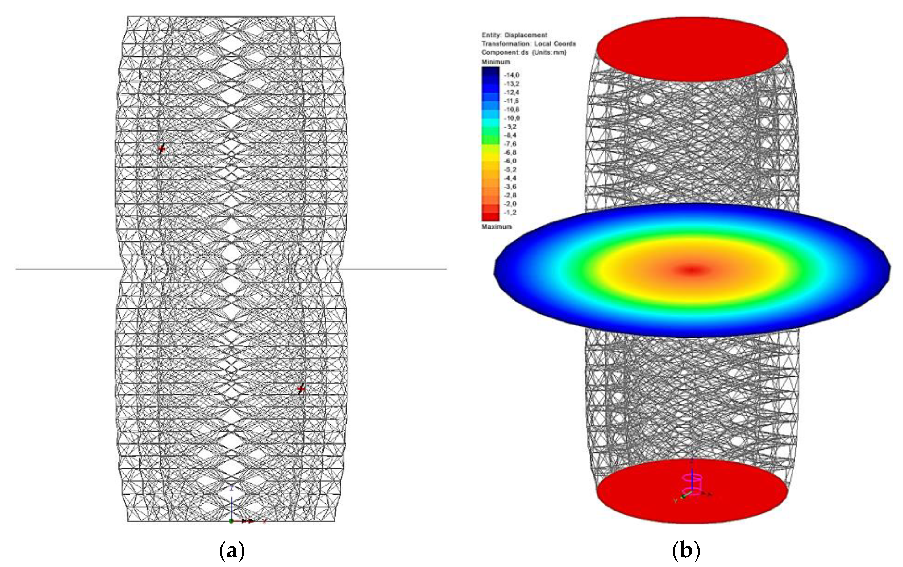
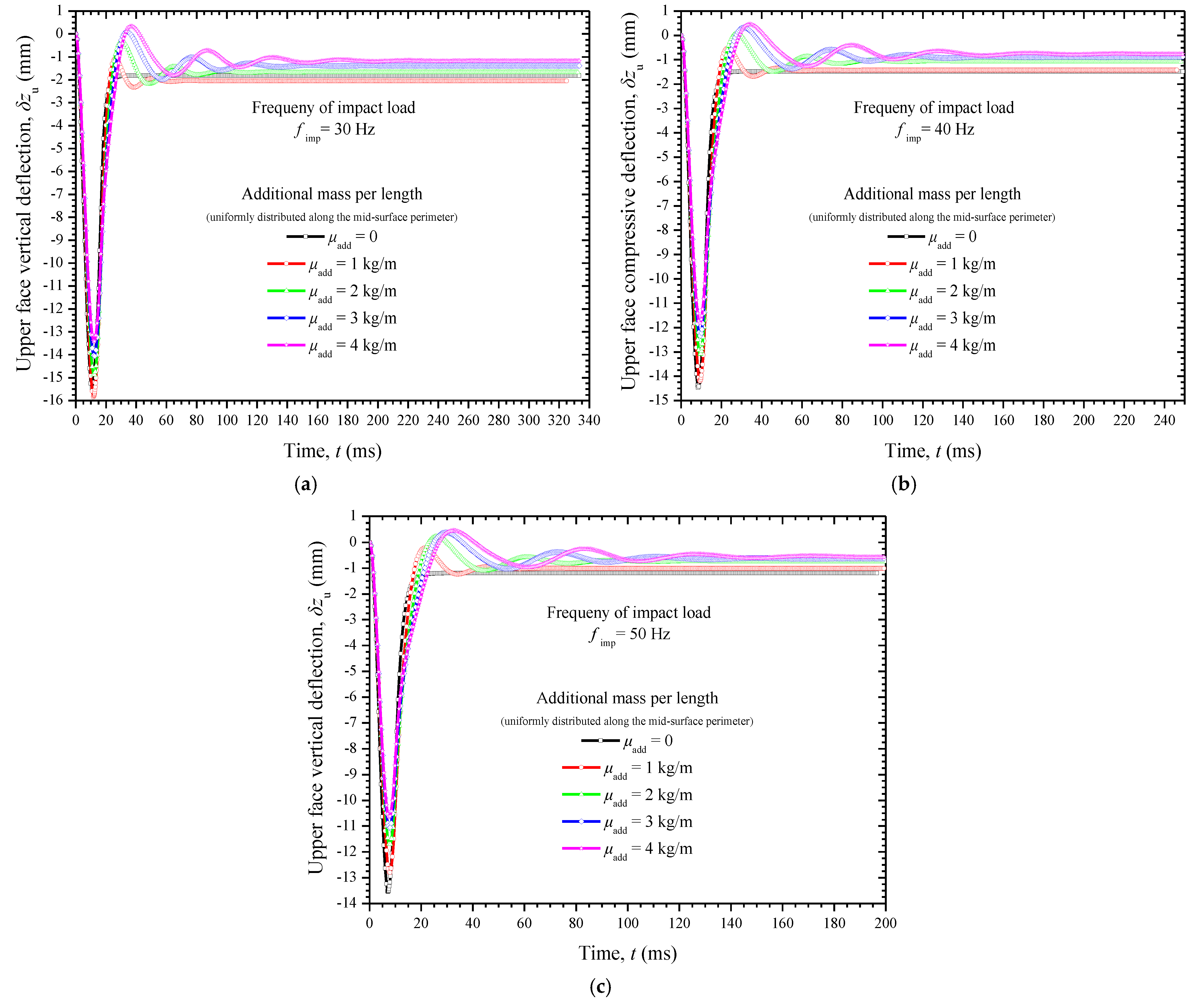
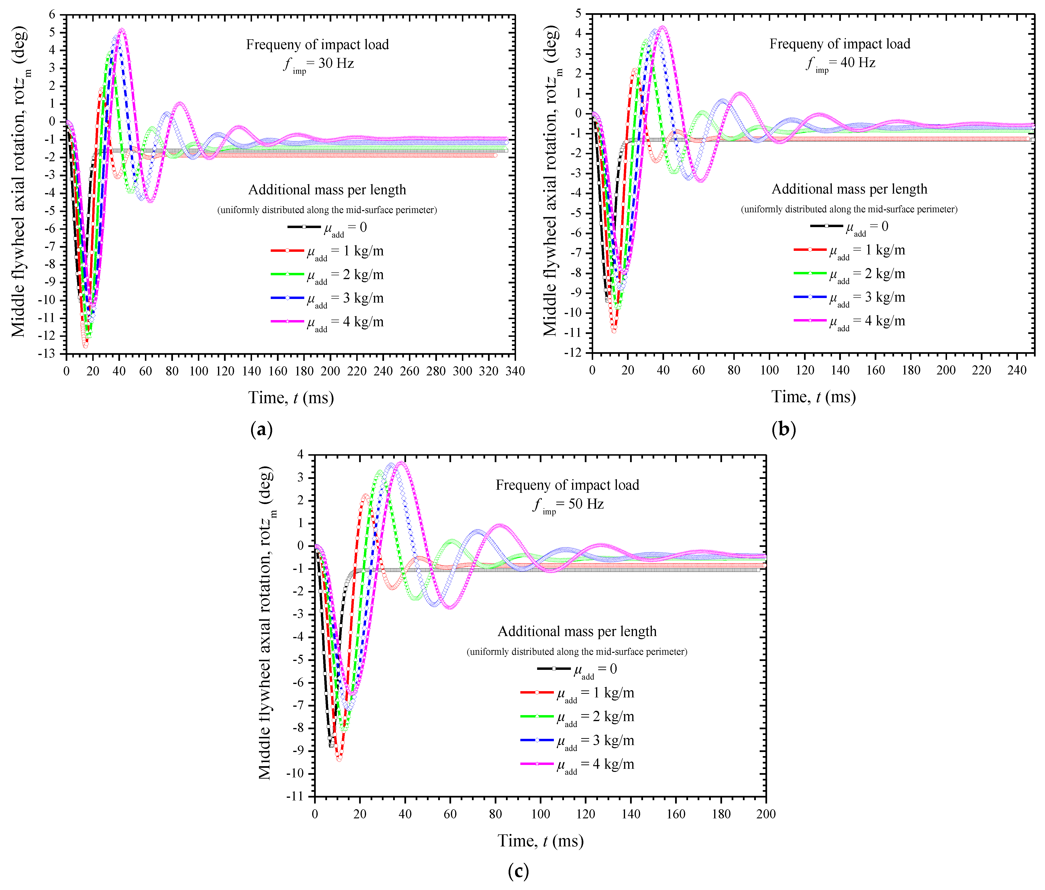
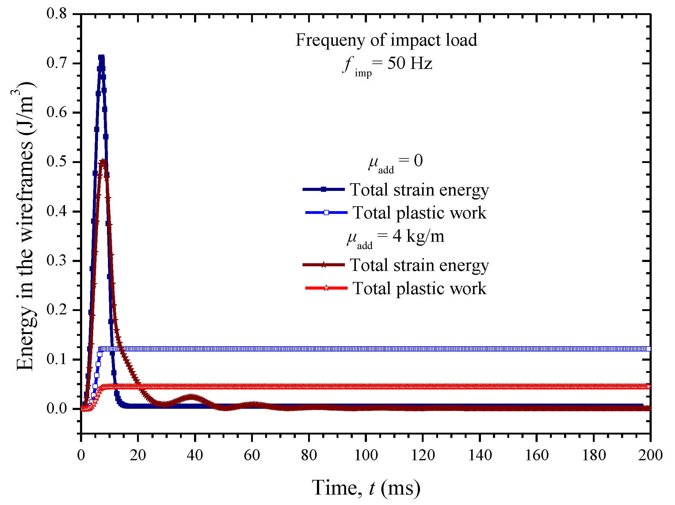
5.3. Dynamic Impact Analysis

In this section, the impact behavior of the joint is investigated for various compressive shock loadings uniformly applied on the upper face. The numerical tests were associated with relatively small impact frequencies f imp of up to 50 Hz, which resembled low-velocity impact cases. The same constraints were hypothesized as in the static simulations. The considered impact load could be represented by a half-sine compressive stress pulse [38], using the following time-dependent function:
σ z ( t ) = { σ z max sin ( 2 π f imp ) , 0 t 0.5 f imp 1 0 , t > 0.5 f imp 1
where the maximum level of compressive stress is taken to be equal to σ z max = 0.5 MPa in order to avoid crack initiations and fractures in the polymeric wireframe. The specific stress considering the area A u = π r u 2 of the upper face of the joint corresponded to a maximum impact force of about 100 kg.
The implicit dynamic numerical simulations of the joint were conducted by assuming that a non-structural mass per unit length μ add was uniformly added around the perimeter of the flywheel, which was equal to 2 π R m . A variety of perimetrically distributed mass cases were tested, i.e., μ add = 0 , 1 , 2 , 3 , 4 Kg / m , to find the optimal design scenario, in terms of the flywheel mass, that offered enhanced impact protection. The relevant conclusions could be indirectly reached by observing the permanent plastic deformations in the load-carrying wireframes. The dynamic simulations were carried out for a time interval equal to 20 times the impact load duration ( 10 f imp 1 ) to reach a steady state for the joint.
The time-variation of the axial vertical deflection of the upper face of the joint, with respect to the added mass magnitude around the perimeter of the flywheel, is depicted in Figure 11a–c for three different impact frequencies f imp of 30, 40, and 50 Hz, respectively. Similarly, the time-dependency of the flywheel torsion angle with respect to the added mass magnitude around its perimeter is depicted in Figure 12a–c considering impact loads governed by a 30, 40, and 50 Hz frequency, respectively. Generally, the numerical data corresponding to the steady-state deformation of the joint at t 10 f imp 1 revealed that the increase in the flywheel perimetric mass led to a distinct decrease in both the vertical upper face deflection as well as the flywheel twisting. These types of deformations corresponded to the permanently deformed configuration of the joint that remained after the finalization of the impact-induced vibration. This “spring-back” phenomenon was observed due to the special microstructure of the triple-wall tubular wireframes. The flywheel was forced to rotate by the two wireframes and thus absorb the impact’s kinetic energy. Then, most of the temporarily saved energy was conversely transferred from the flywheel to the upper face of the joint, and vice versa. However, this vibrational response and resulting energy exchange effectively decayed with time because of the special damping mechanisms provided by the architecture and the inherent damping of the metamaterial. Figure 13 illustrates the time variation of the total strain energy in the tubular wireframes considering the simulation of the joint under the impact load at 50 Hz. To better demonstrate the effect of the mass magnitude around the flywheel, the mass case μ add = 0 was set to contrast with the mass case μ add = 4 Kg / m . As it can be seen, the total strain energy of both the upper and lower wireframes was maximized when the impact axial loading reached its peak and then evenly vanished. On the other hand, the total plastic work stored in the beams was stabilized after the load peak. The effect of the mass increase around the flywheel became distinct due to the higher remaining plastic work observed for the case of μ add = 4 Kg / m .
To summarize the whole numerical outcome, Figure 14 is given, which demonstrates the fact that the impact resistance of the joint may be efficiently tuned and controlled by the flywheel mass magnitude. This figure presents the total plastic deformation work w pl in both the upper and bottom wireframes with respect to the added mass around the flywheel. As it may be seen from the specific figure, less plastic work was produced by the wireframes as the flywheel mass increased, implying that these load-carrying components received a less significant permanent deformation and damage. However, special care and extensive parametric studies are required for each frequency in order to select the proper mass adjustment. For example, the addition of a perimetric mass μ add = 1 kg / m under an impact frequency of 30 Hz seemed not to have any positive effect on the wireframe’s structural health.
It should be mentioned that due to the complexity of performing impact test measurements, the experimental dynamic investigation of the proposed joint is to be performed in a future study with the use of an even more specialized—in terms of inherent damping—raw material.

6. Concluding Remarks

A metamaterial-based joint, intended to be created by 3D printing, was proposed. The architecture of the joint was inspired by the molecular structure of CNTs. Concentric triple-wall hexagonal tubular wireframes, based on the atomistic structure of the armchair (10,10) SWCNT, were utilized. Numerous helical wire-reinforcements were incorporated into the tubular microstructures to enable the partial transformation of external compressive loadings to the twisting of a core inertia disk playing the role of a flywheel. The parametric conducted studies proved that the magnitude of the mass of the flywheel disk may control the extent of the compressive damage of the joint due to low-velocity impact loadings. Depending on the magnitude and frequency of the half-sine impact pulse, a specific amount of mass may be added around the perimeter of the flywheel in order to tune the overall dynamic behavior of the proposed joint in favor of its impact resistance characteristics. The built material that was tested here, i.e., a UV-curable polyurethane acrylate resin, may be replaced by a hyperelastic material of higher damping properties to improve the energy-absorbing capabilities of the proposed joint. The overall size and architecture of the joint may be changed to meet other design criteria, which include different types of load and failure resistance properties, thereby extending its range of possible application areas.

Author Contributions

Conceptualization, G.I.G.; methodology, G.I.G. and S.K.G.; software, G.I.G. and S.K.G.; validation, G.I.G. and S.K.G.; formal analysis, G.I.G. and S.K.G.; investigation, G.I.G. and S.K.G.; resources, G.I.G. and S.K.G.; data curation, G.I.G. and S.K.G.; writing—original draft preparation, G.I.G. and S.K.G.; writing—review and editing, G.I.G. and S.K.G.; visualization, G.I.G. and S.K.G.; supervision, G.I.G. and S.K.G.; project administration, G.I.G. and S.K.G. All authors have read and agreed to the published version of the manuscript.

Funding

This research received no external funding.

Institutional Review Board Statement

Not applicable.

Informed Consent Statement

Not applicable.

Data Availability Statement

The data presented in this study are available on request from the corresponding author.

Conflicts of Interest

The authors declare no conflict of interest.

References

  1. Zhang, Q.; Huang, J.-Q.; Qian, W.-Z.; Zhang, Y.; Wei, F. The Road for Nanomaterials Industry: A Review of Carbon Nanotube Production, Post-Treatment, and Bulk Applications for Composites and Energy Storage. Small 2013, 9, 1237–1265. [Google Scholar] [CrossRef] [PubMed]
  2. Surjadi, J.U.; Gao, L.; Du, H.; Li, X.; Xiong, X.; Fang, N.X.; Lu, Y. Mechanical Metamaterials and Their Engineering Applications. Adv. Eng. Mater. 2019, 21, 1800864. [Google Scholar] [CrossRef] [Green Version]
  3. Wu, Q.; Miao, W.-S.; Zhang, Y.-D.; Gao, H.-J.; Hui, D. Mechanical properties of nanomaterials: A review. Nanotechnol. Rev. 2020, 9, 259–273. [Google Scholar] [CrossRef]
  4. Gouadec, G.; Colomban, P. Raman Spectroscopy of nanomaterials: How spectra relate to disorder, particle size and mechanical properties. Prog. Cryst. Growth Charact. Mater. 2007, 53, 1–56. [Google Scholar] [CrossRef] [Green Version]
  5. Guz, I.; Rodger, A.; Guz, A.; Rushchitsky, J. Developing the mechanical models for nanomaterials. Compos. Part A Appl. Sci. Manuf. 2007, 38, 1234–1250. [Google Scholar] [CrossRef]
  6. Ariga, K.; Mori, T.; Hill, J.P. Mechanical Control of Nanomaterials and Nanosystems. Adv. Mater. 2012, 24, 158–176. [Google Scholar] [CrossRef]
  7. Tang, Q.; Zhou, Z.; Chen, Z. Graphene-related nanomaterials: Tuning properties by functionalization. Nanoscale 2013, 5, 4541–4583. [Google Scholar] [CrossRef]
  8. Baimova, Y.A.; Murzaev, R.T.; Dmitriev, S. Mechanical properties of bulk carbon nanomaterials. Phys. Solid State 2014, 56, 2010–2016. [Google Scholar] [CrossRef]
  9. Zaeri, M.; Ziaei-Rad, S.; Vahedi, A.; Karimzadeh, F. Mechanical modelling of carbon nanomaterials from nanotubes to buckypaper. Carbon 2010, 48, 3916–3930. [Google Scholar] [CrossRef]
  10. Wang, Z.; Gao, F.; Li, N.; Qu, N.; Gou, H.; Hao, X. Density functional theory study of hexagonal carbon phases. J. Phys. Condens. Matter 2009, 21, 235401. [Google Scholar] [CrossRef]
  11. Liarte, D.B.; Stenull, O.; Lubensky, T.C. Multifunctional twisted kagome lattices: Tuning by pruning mechanical metamaterials. Phys. Rev. E 2020, 101, 063001. [Google Scholar] [CrossRef] [PubMed]
  12. Su, Y.; Xu, X.; Shi, J.; Huang, G. A 3D Mechanism-driven Hexagonal Metamaterial: Evaluation of Auxetic Behavior. Int. J. Mech. Sci. 2021, 209, 106699. [Google Scholar] [CrossRef]
  13. Ren, X.; Shen, J.; Ghaedizadeh, A.; Tian, H.; Xie, Y.M. Experiments and parametric studies on 3D metallic auxetic metamaterials with tuneable mechanical properties. Smart Mater. Struct. 2015, 24, 095016. [Google Scholar] [CrossRef]
  14. Cui, H.; Hensleigh, R.; Chen, H.; Zheng, X. Additive Manufacturing and size-dependent mechanical properties of three-dimensional microarchitected, high-temperature ceramic metamaterials. J. Mater. Res. 2018, 33, 360–371. [Google Scholar] [CrossRef] [Green Version]
  15. Dragoni, E.; Ciace, V.A. Mechanical design and modelling of lightweight additively manufactured lattice structures evolved from regular three-dimensional tessellations. Proc. Inst. Mech. Eng. Part C J. Mech. Eng. Sci. 2021, 235, 1759–1773. [Google Scholar] [CrossRef]
  16. Wickeler, A.L.; Naguib, H.E. Novel origami-inspired metamaterials: Design, mechanical testing and finite element modelling. Mater. Des. 2020, 186, 108242. [Google Scholar] [CrossRef]
  17. Mizzi, L.; Attard, D.; Gatt, R.; Dudek, K.K.; Ellul, B.; Grima, J.N. Implementation of periodic boundary conditions for loading of mechanical metamaterials and other complex geometric microstructures using finite element analysis. Eng. Comput. 2020, 37, 1765–1779. [Google Scholar] [CrossRef]
  18. Ghaedizadeh, A.; Shen, J.; Ren, X.; Xie, Y.M. Tuning the Performance of Metallic Auxetic Metamaterials by Using Buckling and Plasticity. Materials 2016, 9, 54. [Google Scholar] [CrossRef]
  19. Coulais, C. As the extension, so the twist. Science 2017, 358, 994–995. [Google Scholar] [CrossRef]
  20. Cheng, L.; Tang, T.; Yang, H.; Hao, F.; Wu, G.; Lyu, F.; Bu, Y.; Zhao, Y.; Zhao, Y.; Liu, G.; et al. The Twisting of Dome-Like Metamaterial from Brittle to Ductile. Adv. Sci. 2021, 8, 2002701. [Google Scholar] [CrossRef]
  21. Ji, J.; Luo, Q.; Ye, K. Vibration control based metamaterials and origami structures: A state-of-the-art review. Mech. Syst. Signal Process. 2021, 161, 107945. [Google Scholar] [CrossRef]
  22. Chen, Y.-L.; Wang, X.-T.; Ma, L. Damping mechanisms of CFRP three-dimensional double-arrow-head auxetic metamaterials. Polym. Test. 2020, 81, 106189. [Google Scholar] [CrossRef]
  23. Qiao, J.; Chen, C. Impact resistance of uniform and functionally graded auxetic double arrowhead honeycombs. Int. J. Impact Eng. 2015, 83, 47–58. [Google Scholar] [CrossRef]
  24. Ma, L.; Chen, Y.-L.; Yang, J.-S.; Wang, X.-T.; Ma, G.-L.; Schmidt, R.; Schröder, K.-U. Modal characteristics and damping enhancement of carbon fiber composite auxetic double-arrow corrugated sandwich panels. Compos. Struct. 2018, 203, 539–550. [Google Scholar] [CrossRef]
  25. Miniaci, M.; Krushynska, A.; Bosia, F.; Pugno, N.M. Large scale mechanical metamaterials as seismic shields. New J. Phys. 2016, 18, 083041. [Google Scholar] [CrossRef]
  26. Van Belle, L.; Claeys, C.; Deckers, E.; Desmet, W. On the impact of damping on the dispersion curves of a locally resonant metamaterial: Modelling and experimental validation. J. Sound Vib. 2017, 409, 1–23. [Google Scholar] [CrossRef]
  27. Rebelo, H.; Lecompte, D.; Cismasiu, C.; Jonet, A.; Belkassem, B.; Maazoun, A. Experimental and numerical investigation on 3D printed PLA sacrificial honeycomb cladding. Int. J. Impact Eng. 2019, 131, 162–173. [Google Scholar] [CrossRef]
  28. Santos, F.; Rebelo, H.; Coutinho, M.; Sutherland, L.; Cismasiu, C.; Farina, I.; Fraternali, F. Low velocity impact response of 3D printed structures formed by cellular metamaterials and stiffening plates: PLA vs. PETg. Compos. Struct. 2021, 256, 113128. [Google Scholar] [CrossRef]
  29. Chen, X.; Ji, Q.; Wei, J.; Tan, H.; Yu, J.; Zhang, P.; Laude, V.; Kadic, M. Light-weight shell-lattice metamaterials for mechanical shock absorption. Int. J. Mech. Sci. 2020, 169, 105288. [Google Scholar] [CrossRef]
  30. Brecher, C.; Fey, M.; Bäumler, S. Damping models for machine tool components of linear axes. CIRP Ann. 2013, 62, 399–402. [Google Scholar] [CrossRef]
  31. Kołoczek, J.; Kwon, Y.-K.; Burian, A. Characterization of spatial correlations in carbon nanotubes-modelling studies. J. Alloys Compd. 2001, 328, 222–225. [Google Scholar] [CrossRef]
  32. Shan, J.; Yang, Z.; Chen, G.; Hu, Y.; Luo, Y.; Dong, X.; Zheng, W.; Zhou, W. Design and Synthesis of Free-Radical/Cationic Photosensitive Resin Applied for 3D Printer with Liquid Crystal Display (LCD) Irradiation. Polymers 2020, 12, 1346. [Google Scholar] [CrossRef] [PubMed]
  33. Ahmad, K.W.H.; Mohamad, Z.; Othman, N.; Man, S.H.C.; Jusoh, M. The mechanical properties of photopolymer prepared via 3d stereolithography printing: The effect of uv curing time and anisotropy. Chem. Eng. Trans. 2020, 78, 565–570. [Google Scholar]
  34. LUSAS Version 15.0: Theory Volume Manual 1 and 2; LUSAS: Kingston Upon Thames: Surrey, UK, 2013.
  35. Chowdhury, I.; Dasgupta, S.P. Computation of Rayleigh damping coefficients for large systems. Electron. J. Geotech. Eng. 2003, 8, 1–11. [Google Scholar]
  36. Liao, F.; Zeng, X.-R.; Li, H.-Q.; Lai, X.-J.; Zhao, F.-C. Synthesis and properties of UV curable polyurethane acrylates based on two different hydroxyethyl acrylates. J. Central South Univ. 2012, 19, 911–917. [Google Scholar] [CrossRef]
  37. Malas, A.; Isakov, D.; Couling, K.; Gibbons, G.J. Fabrication of High Permittivity Resin Composite for Vat Photopolymerization 3D Printing: Morphology, Thermal, Dynamic Mechanical and Dielectric Properties. Materials 2019, 12, 3818. [Google Scholar] [CrossRef] [PubMed] [Green Version]
  38. McLaskey, G.C.; Glaser, S.D. Hertzian impact: Experimental study of the force pulse and resulting stress waves. J. Acoust. Soc. Am. 2010, 128, 1087–1096. [Google Scholar] [CrossRef] [PubMed] [Green Version]
Figure 1. Design of the proposed metamaterial-based joint.
Applsci 11 11139 g001
Figure 2. The architecture of the triple-wall wireframe.
Applsci 11 11139 g002
Figure 3. Experimental equipment for investigating the mechanical properties of the raw material: (a) utilized 3D printer, (b) 3D-printed specimens, and (c) their testing in the utilized tensile machine.
Applsci 11 11139 g003
Figure 4. Experimental stress–strain curves for the 3D-printed material.
Applsci 11 11139 g004
Figure 5. Discretized joint with beam and shell 3D finite elements.
Applsci 11 11139 g005
Figure 6. Critical buckling: (a) deformed meshed geometry of the joint and (b) contours of the strain energy density of the triple-wall wireframe (in the range of 0–100 arbitrary units).
Applsci 11 11139 g006
Figure 7. Stress–strain curve of the joint under axial compression.
Applsci 11 11139 g007
Figure 8. Experimental setup for measuring the static compressive behavior of the 3D-printed joint: (a) curing of some parts after their printing, (b) an undeformed 3D-printed joint, and (c) a deformed joint prototype during the compression test (180 small recesses are printed around the flywheel to help the rotation angle measurements).
Applsci 11 11139 g008
Figure 9. Joint just before fracture: (a) first two points of failure in the deformed mesh and (b) contours of rotational displacement on the flywheel.
Applsci 11 11139 g009
Figure 10. Relation between twisting and the vertical axial deflection of the middle flywheel due to the joint axial compression.
Applsci 11 11139 g010
Figure 11. Time variation of the upper face vertical deflection under a half−sine impact shock characterized by a frequency of (a) 30 Hz, (b) 40 Hz, and (c) 50 Hz, for a variety of mass additions around the flywheel perimeter.
Applsci 11 11139 g011
Figure 12. Time variation of the middle flywheel axial rotation under a half−sine impact shock characterized by a frequency of (a) 30 Hz, (b) 40 Hz, and (c) 50 Hz, for a variety of mass additions around the flywheel perimeter.
Applsci 11 11139 g012
Figure 13. Time variation of both the total strain energy and plastic deformation work in the wireframes under a 50 Hz half-sine impact shock, for zero and 4 kg/m mass addition around the flywheel perimeter.
Applsci 11 11139 g013
Figure 14. Total plastic deformation work in the wireframes versus the mass addition around the flywheel perimeter for several impact frequencies.
Applsci 11 11139 g014
Table 1. Information regarding the present 3D printer and printing process profile.
Creality LD-002H UV Resin 3D PrinterASTM Standardized 3D Printed Specimens
SpecificationValuePropertyValue
Modeling Technology:LCDLayer Height:0.05 mm
Print Size:130 mm × 82 mm × 160 mmBottom Layer Count:8
Print Speed:1–4 s/layerExposure Time:6 s
Screen:3.5-inch touch screenBottom Exposure Time:50 s
Machine Size:221 mm × 221 mm × 403 mmLight-off Delay:0
Package Size:295 mm × 295 mm × 540 mmBottom Light-off Delay:0
Machine Weight:8.3 kgBottom Lift Distance:5 mm
Layer Height:0.03–0.05 mmLifting Distance:5 mm
XY axis Precision:0.051 mmBottom Lift Speed:20 mm/min
Lifting Speed:65 mm/min
Retract Speed:100 mm/min
Publisher’s Note: MDPI stays neutral with regard to jurisdictional claims in published maps and institutional affiliations.

