Article

Analysis of a Preliminary Design Approach for Conformal Lattice Structures

by
Pierandrea Dal Fabbro
1,*,
Stefano Rosso
2,
Alessandro Ceruti
3,
Diego Boscolo Bozza
4,
Roberto Meneghello
2,
Gianmaria Concheri
1 and
Gianpaolo Savio
1
1
Department of Civil, Environmental, and Architectural Engineering, University of Padova, Via Venezia, 1, 35131 Padova, Italy
2
Department of Management and Engineering, University of Padova, Stradella S. Nicola, 3, 36100 Vicenza, Italy
3
Department of Industrial Engineering, University of Bologna, Viale Risorgimento, 2, 40136 Bologna, Italy
4
EnginSoft SpA, Via Giambellino, 7, 35129 Padova, Italy
*
Author to whom correspondence should be addressed.
Appl. Sci. 2021, 11(23), 11449; https://doi.org/10.3390/app112311449
Submission received: 20 October 2021 / Revised: 25 November 2021 / Accepted: 26 November 2021 / Published: 2 December 2021

Abstract

:

Featured Application

Automotive, aeronautical, space, biomedical, and marine engineering.

Abstract

An important issue when designing conformal lattice structures is the geometric modeling and prediction of mechanical properties. This paper presents suitable methods for obtaining optimized conformal lattice structures and validating them without the need for high computational power and time, enabling the designer to have quick feedback in the first design phases. A wireframe modeling method based on non-uniform rational basis spline (NURBS) free-form deformation (FFD) that allows conforming a regular lattice structure inside a design space is presented. Next, a previously proposed size optimization method is adopted for optimizing the cross-sections of lattice structures. Finally, two different commercial finite element software are involved for the validation of the results, based on Euler–Bernoulli and Timoshenko beam theories. The findings highlight the adaptability of the NURBS-FFD modeling approach and the reliability of the size optimization method, especially in stretching-dominated cell topologies and load conditions. At the same time, the limitation of the structural beam analysis when dealing with thick beams is noted. Moreover, the behavior of different kinds of lattices was investigated.

1. Introduction

Nowadays, the development of additive manufacturing (AM) technologies increases the freedom in the production of parts with a complex shape, enabling the designer to overcome the limitations imposed by traditional manufacturing technologies. Indeed, the conventional product design evolves toward the design for additive manufacturing (DfAM) concept [1]. Thanks to the additive processes, which are based on a layer-by-layer manufacturing approach, in DfAM, it is possible to exploit four forms of design complexity: shape complexity, functional complexity, hierarchical complexity, and material complexity [2].
Several design methods are developed for these goals, mostly inspired by nature, where each approach is the result of millions of years of evolution. Among them, some material distribution strategies mimic the mineral structures and the animals’ skeletons. They are called cellular structures and are obtained by the arrangement and the repetition of a unit cell in the space [3]. Lattice structures present interesting properties: lightweight, high strength, energy absorption, and vibration reduction [4,5,6,7,8]. These properties are directly related to the structure shape, the cell topology, the cell dimension, and the cell element size. The structure shape can be categorized as regular, random, and pseudo-random [9]. Regular lattice structures are uniform, with constant topology and aspect ratio along the design volume, whereas random and pseudo-random are non-uniform [9,10,11]. Random structures present a casual organization, geometry, and dimension of the cell; usually, they are associated with natural materials and foams [3,12]. Pseudo-random structures are obtained, maintaining the topology but varying both the size and geometry; they can be warped or conformal [13,14]. Warped structures are characterized by a deformed unit cell; this deformation can be driven by the results of a finite element analysis (FEA), a gradient, or other functional requirements [13]. Conformal structures present unit cells with different sizes and geometry to adapt and conform to the external boundary of the model; conformal lattices better adapt to free-form shapes since they follow the borders and the cells never interrupt, providing a better stiffness and resistance to the entire model [14,15]. Only a few studies are available in the literature regarding this kind of lattices [15,16], and effective design methods are needed.
If produced with traditional manufacturing techniques, the foams have a random distribution of the cells and walls and are usually obtained by expanding a liquid, a solid, or a gel with a foaming agent. They are mechanically characterized by low stiffness, and the walls of the cells tend to bend when they are loaded. Due to that, these structures are called bending-dominated. More organized lattices, instead, behave as stretching-dominated, with high structural efficiency [4]. This behavior can be described by the Maxwell stability criterion for 3D unit cells [8], generalized by Calladine [7,17] using the equation:
M = b 3 j + 6 = s m
where b is the number of struts, j is the number of locked joints, s is the number of states of self-stress, and m is the number of mechanisms. According to the Maxwell criterion, if M is lower than 12, the 3D cell is bending-dominated; otherwise, it is stretching-dominated, and it is redundant from a rigidity point of view. However, the mechanical behavior of the lattice also depends on the unit cell topology, orientation, periodicity, and the load direction; for these reasons, it is not possible to determine the deformation mechanism directly from the Maxwell criterion. For example, a lattice structure composed of simple cubic cells is defined as bending-dominated but, when loaded along with the directions of its main axes, it can exhibit stretching-dominated behavior [5]. Lastly, a fundamental parameter of lattice structures is the relative density, defined as the ratio between the volume of the cellular structure and the volume of the design space. With their model [18], Gibson and Ashby demonstrated that it is possible to correlate the lattice mechanical proprieties, such as Young’s modulus, to the relative density. Indeed, material selection charts that are related to those properties are available in the literature for the designer as a tool for the selection of the desired relative density and cell [4,5]. Tobias et al. [19] compared a significant amount of data of experimental compression tests on 3D-printed lattices available in the literature with the predictions of the Gibson-Ashby model. The findings highlight a suitable correlation between the experimental tests and the mathematical model; anyway, a precise prediction of these properties is not possible, so the model is intended to be used in the early design stages. Kaur et al. [20] studied the deformation of 3D-printed lattices, obtained by various thermoplastic materials and tested by compression testing and FEA; they found that the material can influence the bending and stretching-dominated behavior of the lattice structures.
Moreover, the cell element size can be optimized to satisfy structural requirements. Size optimization, together with the shape and topology optimization, is part of the structural optimization and aims to iteratively find the best configuration of the size of the elements, both beams diameter and shell thickness, to enhance the structural properties of the structure [21,22,23]. Once the lattice structure has been optimized, the information is gathered, and the geometrical model has to be obtained. Even though some lattice design tools were integrated inside commercial computer-aided design (CAD) software [24,25,26], the lack of suitable modeling methods for such structures has been highlighted in the literature [27,28,29]. Traditional CAD software are usually based on boundary representation (B-Rep) modeling approaches through function-based methods, such as non-uniform rational B-splines (NURBS) or discrete mesh methods [30]. Modeling conformal lattice structures inside these environments is challenging. Boolean, offsetting, and filleting operations on complex shapes require high computational resources and time, and, even worse, they often fail; furthermore, lattice structures with a high number of elements are difficult to manage and visualize. One more issue comes from the file format when exchanging data between different software; especially with AM parts, the integration between CAD software, where the part is modeled, computer-aided engineering (CAE) software, where the part is optimized and validated, and computer-aided manufacturing (CAM) software, where the part is prepared for the production phase, is fundamental, and a suitable file format is required to describe the parts and to be able to interact and go “back and forth” at every time [31,32]. To avoid these limitations, the design of lattice structure can be performed via wireframe modeling, a suitable method for the design and optimization of lattice structure by describing the geometry using mono-dimensional elements [33]. The lattice structure, constructed as an array of unit cells, can be morphed along a direction or surfaces thanks to advanced CAD tools [32,34,35]. An alternative method for conforming a lattice inside a design space, already used in virtual reality and biomedical fields, is the NURBS free-form deformation (FFD) technique, able to morph any kind of geometry into a design domain [14]. It is based on the creation of a trivariate tensor volume around the object; the volume can be deformed through its vertices to deform the object. Several evolutions of the FFD approach were developed from the first proposed by Sederberg and Parry [36], such as improvements in the flexibility of the control volume, combining several tricubic Bezier volumes [37], and enhancing the control of deformations through vertex weighting via NURBS-based approach [38]. Some software [39,40] already implemented this method through the creation of a trivariate NURBS cage around the object and the translation of its control points.
Furthermore, performing FEAs on lattice structures is not trivial due to the complex polyhedral mesh creation and the high number of nodes and finite elements that have to be processed. Again, high computational resources and time are needed. At the same time, FEAs need to be performed both during the size optimization phase and during the final validation of the model and cannot be neglected. Due to these reasons, alternative structural analysis methods, such as the asymptotic homogenization (AH) and mono-dimensional element methods, were developed [41,42,43,44]. In the AH approach, the lattice structure is studied as a fully dense material that has equivalent mechanical properties; this allows reducing the complexity of the model, but as a drawback, AH precludes working with anisotropic structures, so it is not possible to analyze pseudo-random and random lattice structures. As an alternative, the mono-dimensional finite element methods (FEM) based on the beam theory can be used. Two types of beams theory are widely used in the commercial FEM software: Euler–Bernoulli and Timoshenko. The Euler–Bernoulli approach assumes that the shear deformation is negligible compared to the bending deformation, so the beam cross-section remains perpendicular to its neutral axis. The critical parameter of this theory is the slenderness ratio, defined as the ratio between the length and the size of the side of the cross-section of the beam that affects the flexural rigidity matrix. When this value is low, in bending conditions, the flexural rigidity increases exponentially, causing underestimation of the deflection result. Due to the typical small dimensions of the elements of the lattice structures in AM, this ratio becomes an applicability limit [45]. The Timoshenko theory includes the deformation contribution coming from the shear stress, allowing the rotation between the cross-section and the neutral axis of the bending curve; therefore, it is more accurate. The limitation of this theory is based on the beam thickness parameter; if it is too small, a phenomenon called shear locking can occur. The shear locking problem lies in a bad schematic of the shear part of the elastic energy. To avoid the issue, a convergence study needs to be performed subdividing the beam into n elements until the results are comparable to the exact theoretical values of displacement [46].
Bacciaglia et al. [47] reconstructed a lattice structure wireframe from a B-Rep using a novel voxel approach. They then created an ad-hoc MATLAB algorithm to transfer the mono-dimensional geometry in the FEM environment. Finally, they compared the result of the Euler–Bernoulli beam structural analysis approach with the results of the AH and 3D mesh FEM analysis approaches. The findings highlight the beam structural analysis has the best time-saving approach, but with uncertainty in the displacement estimation of 15%. Ravari et al. [48] studied the effects of the variation of the beam diameter on the mechanical proprieties of a lattice structure produced by fused filament fabrication. They compared the result of the mechanical tests with the Timoshenko beam and the solid finite element analysis showing a suitable agreement between the stress and Young’s modulus results of the solid model and the experimental tests. The mono-dimensional beam theory showed a better precision in the prediction of the elongation and was more computationally efficient. Campoli et al. [49] carried out an FEA to predict the mechanical proprieties of porous titanium produced using selective laser melting (SLM), taking into account irregularities caused by the manufacturing process, comparing it to the analytical model and the experimental result. They found that the beam approach can predict the proprieties of pours biomaterial manufactured by SLM more accurately than the analytical. A similar conclusion was found by Genovese et al. [50], who studied the compression proprieties of the body-centered cubic (BCC) cell and the diamond (DA) cell, produced by SLM technologies, adopting digital image correlation (DIC) measurements during the experiments. Their numerical results using the beam theory on the BBC framework are more accurate than the ones from the solid model analysis. They hypothesized that the reason is the additional contribution of the stiffness provided by the joints of the struts. The results of the DA are not accurate in predicting the mechanical response of the real structure. Dong et al. [51] proposed to modify the Timoshenko beam element to consider the influence of the joint on the stiffness properties of the lattice structures due to the concentration of the material in the nodal points of the lattices. The validation of their joint stiffening element, through experimental mechanical tests and numerical analyses, demonstrated better accuracy than the traditional beam elements; more, a suitable agreement with experimental results and FE analyses with tetrahedral elements was found, with a considerable reduction in the computational costs. Zhu et al. [12] used the Timoshenko beam theory to determine the effect of the cell irregularity on the mechanical properties of 3D random open-cell foams. Each strut was divided into five elements according to the length of the strut. They found that highly structural irregularity brings to higher elastic and shear modulus but smaller bulk modulus concerning a perfect foam. They also found that their analytical model over-estimated the elastic modulus of a perfect foam with a large relative density. They suggested using a slenderness ratio greater than 4 to use the beam theory correctly. Evangelos et al. [44] studied the elastic modulus and Poisson ratio of a BCC cellular structure by analytical, numerical, and AH methods. Their experimental results are in excellent correlation with the numerical results derived by Timoshenko and AH methods. They also found a deviation of the results when adopting the Euler theory with respect to other numerical approaches when the slenderness ratio is higher than 10.
Even though the research community has proposed several solutions for reducing the simulation times and for simplifying the modeling of uniform lattice structures, a gap found in the literature regards the conformal lattice structures; indeed, the lack of a methodological approach for design, optimization, and geometric modeling inside the same environment was highlighted. Moreover, a comparison among the behavior of different cells in conformal lattices needs to be investigated in more detail [15,32,34,52,53].
Based on the mentioned issues, the aim of this paper is manifold. First, a novel method for designing conformal lattice structures based on the NURBS-FFD approach and for performing a size optimization in the same environment is proposed. The method is implemented using Python programming language and Karamba3D solver in the Rhinoceros environment. The integrated approach enables the exploitation of the previously developed geometric modeling methods based on subdivision surfaces [30]. Then, the mono-dimensional beam algorithm used for the size optimization of the conformal lattice is tested on four cells (simple cubic, body-centered cubic, modified Wallach-Gibson, and diamond), considering the technological limits of the additive manufacturing technologies such as minimum beam diameter and escape holes. Finally, the method was validated by performing numerical analyses based on the mono-dimensional beam theory inside two commercial FEM software, namely ANSYS Mechanical and MSC Nastran.

2. Materials and Methods

The methodology adopted for designing and validating optimized conformal lattice structures is explained in the following sub-sections. In the first subsection, the modeling methodology based on NURBS free-form deformation is described; in the second subsection, the size optimization method is briefly explained; in the third subsection, the validation methods through the beam linear structural analysis are described. The case study is a piston rod previously investigated by Rosso et al. [54,55]. Figure 1 shows the main dimensions of the test case, highlighting in green the design space that was replaced by lattices.

2.1. NURBS Free-Form Deformation Approach for Conformal Wireframe

The modeling of the conformal wireframe is based on the morphing of a lattice structure inside a design space and is performed in Rhinoceros 3D CAD software (release 7.8.2) and the relative visual programming environment Grasshopper.
First, a regular lattice structure is created by repeating the unit cell with a linear array along with the X-, Y-, and Z-axes. Four different beam-based unit cells are used: simple cubic (SC), body-centered cubic (BCC), modified Wallach-Gibson (WG), and diamond (DA) unit cell [56] (Figure 2). These unit cells are selected to show different behavior of bending and stretching-dominated lattices, according to the Maxwell rule [8], and to consider symmetry and the number of elements. The SC and the DA cells have a bending-dominated behavior, whereas the BCC and the WG cells a stretching-dominated one. SC and BCC belong to the same cubic cell family, sharing the beams at the edges of the cube; the main difference is based on the additional beams of the BCC, from the vertices to the center, which reinforce the cell. As opposed to the SC and BCC cells, the WG and DA ones are asymmetric, so the cell orientation affects the results related to the load condition. Finally, BCC and WG have more elements in the unit cell.
Then, each array is morphed by the NURBS-FFD method to fit inside the design space of the piston road, while the straight elements of the cells are transformed into curve elements. More in detail, the NURBS-FFD technique is available in several commercial CAD software such as Rhinoceros, Blender, Autodesk Maya, and Autodesk 3ds Max and provides a user interface that simplifies the transformation of the regular lattice into a conformal one. Indeed, it is sufficient to move the vertices of a trivariate NURBS to adapt a box to the design space, simultaneously transforming the rods contained within it.
The deformation aims to maintain the cell aspect ratio similar to the undeformed cells in the central zone of the design space and, at the same time, cells that conform to the borders at the boundaries. In detail, this is performed by creating a trivariate NURBS volume around the object and moving its control points. The detailed procedure is as follows:
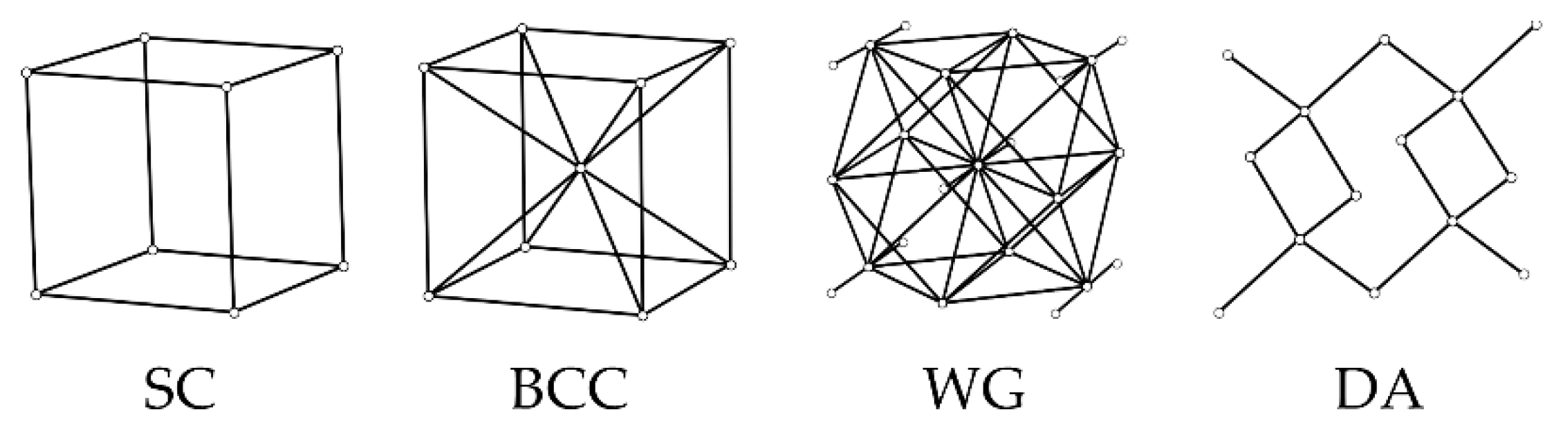
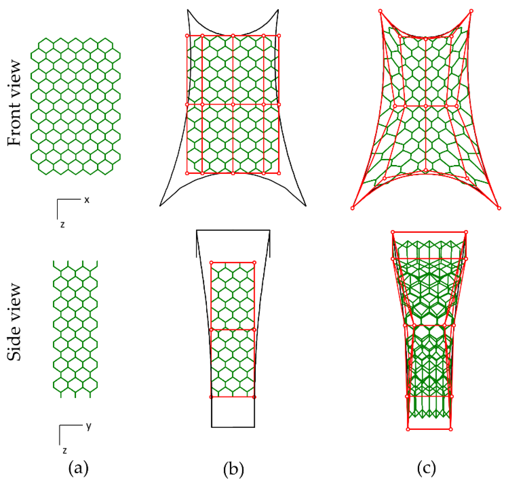
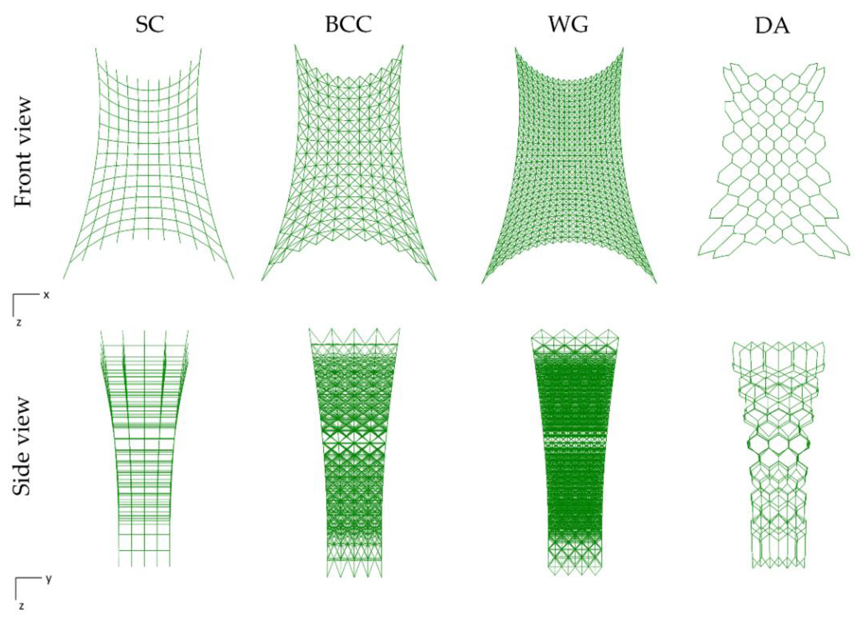
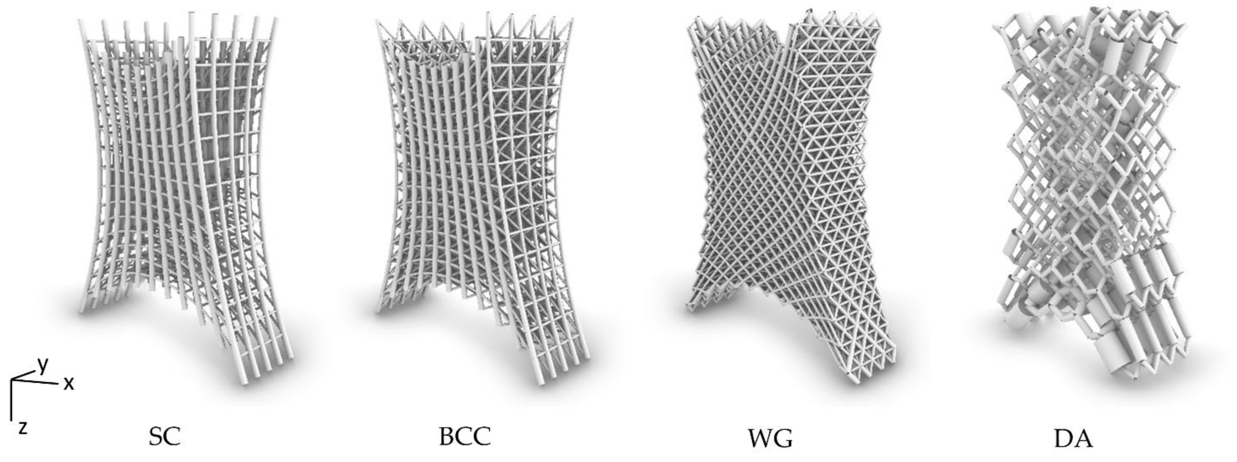
  • A regular wireframe based on the repetition along the X-, Y-, and Z-axis is generated. The number of instances is 14 cells along the Z-direction, 10 cells along the X-direction, and 4 cells along Y-direction for the BC, BCC, and WG. However, for the DA, the instances along the X-direction are 6 to maintain the aspect ratio (Figure 3a);
  • A 3D NURBS volume is built around the wireframe using the Cage-Edit command. In the case study, the cage is governed by 5 control points in X-direction, 2 control points in Y-direction, and 3 control points in Z-direction (Figure 3b).
The control cage is adapted to the vertices of the design space and the curves of the boundaries by moving the control points (Figure 3c).
This approach can be automated by defining a specific transformation of the cage, and it adapts to different geometric configurations of the design space. Moreover, it allows warping transformations if densification of the cells is needed.

2.2. Structural Size Optimization

This work refers to the method firstly implemented by Savio et al. [56] using a Phyton script and exploiting the Karmaba3D libraries [57], a Grasshopper plug-in for performing FEAs, and it is based on the utilization factor described in the Eurocode 3 [58]. The utilization factor considers the axial force, biaxial bending, torsion, shear force, and buckling load in compression. As an input, the method requires the wireframe model, the material properties, the boundary conditions, and the size constraints. Finally, the iterative FEA is run, varying the beam size to obtain the desired utilization for each element inside a predefined range [54].
Two different load cases are applied, a traction load case of 7.5 kN for comparing the result with the previous work of Rosso et al. [54] and a compression load case of −10 kN for evaluating the structure’s stability and buckling effects. The load is evenly applied to the nodes of the beams connected to the big rod’s end (Table 1). All the displacements and rotations of the beams nodes connected to the small rod’s end are locked; the displacements of the beams nodes connected to the big rod’s end are locked along the X- and Y-direction, while they can move along the Z-direction and rotate around all the axes (Figure 4). Even if the boundary conditions do not perfectly represent the actual conditions, they may be sufficient to test and validate the method on different configurations. Due to the impossibility of producing cellular structures with traditional manufacturing technologies, the piston rod is supposed to be produced by AM; in particular, the SLM process, which belongs to the powder bed fusion category [59], is chosen due to its consolidated capability in producing almost fully dense lattices and, more in general, components characterized by mechanical properties similar to the parts obtained by conventional technologies [60,61], and due to its diffusion in the industry [62]. The selected AM machine is the Renishaw AM 400, and the material is the aluminum AlSi10Mg-0403 powder produced by Renishaw [63]. The mechanical proprieties declared by the producer are summarized in Table 2. The material was assumed as a linear elastic isotropic material without considering the influence of the printing direction, and the deformations are assumed to be small. The utilization factor for the optimization is set to (90 ± 1)% of the yield strength. The beam cross-section is circular. The size constraints were defined to avoid interference between the beams, to avoid powder evacuation problems, and considering the manufacturing size constraints given by the SLM technology, especially the minimum manufacturable diameter of beams [64]: the allowed beam diameter ranges from 0.5 to 1.5 mm for the SC, BCC, and WG structures, whereas, due to the bigger cell dimension of the DA lattice, the diameter ranges from 0.95 to 4.75 mm.

2.3. Beam Approach for Linear Structural Analysis

In this section, the implemented beam structural linear analysis approaches are presented. The FEM analyses were performed to validate the optimized lattice structure models.
Three displacement-based FEM software were employed:
  • Karamba3D (1.3.3) plug-in with Rhinoceros 7 (7.8.2) [54]. Karamba3D is a parametric structural engineering tool that performs structural analyses of spatial trusses, frames, and shells, and it is fully embedded in the parametric environment of Grasshopper, the visual programming language inside Rhinoceros. This makes it easy to combine parameterized geometric models, finite element analyses, and optimization algorithms. Karamba3D has been mostly used in the early stage design [65];
  • MSC Patran/Nastran [47]. Patran is a pre-/post-processing software for FEA that provides modeling, meshing, analysis setup, and post processing for solvers. Nastran is a multidisciplinary structural solver for accurate static, dynamic, and thermal analyses;
  • Ansys 2020 R1 Mechanical [44]. Ansys is an FEA software tool for multidisciplinary simulation with a common platform, ANSYS Workbench, that can connect the tools together. As for Nastran, ANSYS Mechanical is the dedicated tool for multidisciplinary structural analyses.
In Karamba3D, the structural beam analysis is based on the Timoshenko beam theory with a linear shape function [65]. In Nastran, the beam model is based on the Euler–Bernoulli beam element. In ANSYS Mechanical, two types of the beam element can be selected: beam 188 (or beam 189) based on the Timoshenko theory and beam 3 based on the Euler–Bernoulli theory; moreover, through the Mechanical APDL interface, it is possible to select the type of the shape function (linear, quadratic, cubic) to define more integration points along with the element for enhancing the results and visualization accuracy; in this work, the beam 188 element with a quadratic shape function was selected.
In the Euler–Bernoulli beam theory, it is assumed that the plane cross-sections remain plain and perpendicular to the axis of the beam after the deformation; this assumption involves that all the transverse shear strains are null. The Timoshenko beam theory is an extension of the Euler–Bernoulli one: the plane of the sections remains plain but not necessarily perpendicular to the longitudinal axis after the deformation, thus admitting a nonzero transverse shear strain [66]. In operational terms, for a static case, Timoshenko’s beam model, if compared to Euler–Bernoulli’s model, has an additional energetic contribution given by the shear. A number of refined theories have been proposed for the analysis of shear deformable beams in the last four decades [67,68,69,70,71,72], but they are not adopted by the used commercial FEM software and are beyond the scope of this work. Regardless of the software, a simplification of the geometry is mandatory since the conformal cells are described by curves, whereas the application of the beam theories requires lines. To do this, the start and the end of each transformed element are connected by a line.
The beam structural validation using Karamba3D is carried out in the same environment of the NURBS-FFD modeling approach and the size optimization, so the information about the structure, material, and boundary conditions are directly available and easy to modify. Patran/Nastran and Ansys software require instead to import the model information through text files and to develop ad-hoc scripts using the dedicated programming languages of the FEM software. The lattice structure wireframe information needed to reconstruct the model are the following:
  • The node coordinates list contains the cartesian coordinates of all the nodes of the structure;
  • The beam connection list contains the indexes of the starting and ending node of each beam of the structure;
  • The beam size list contains the diameter of the cross-section of each beam of the structure.
  • The load, constraints, and material are added inside the CAE environment and correspond to the boundary conditions of the structural size optimization (Figure 4):
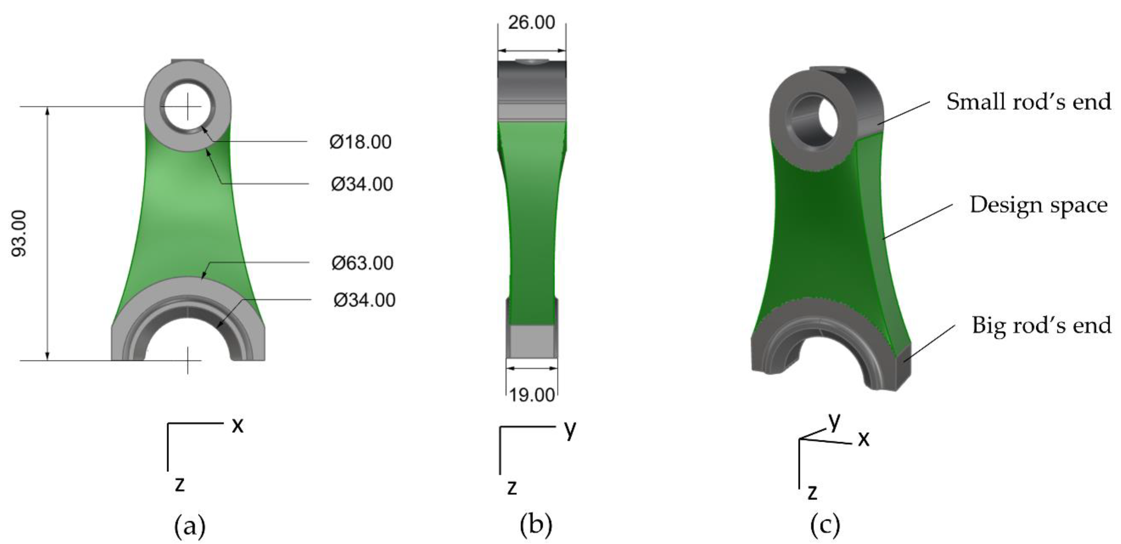
  • Two load cases: 7.5 kN (traction) and -10 kN (compression) applied to the nodes of the beams connected to the big rod’s end;
  • The displacements along the X- and Y-direction of the nodes of the beams connected to the big rod’s end are locked;
  • The displacements and rotations of the nodes of the beams connected to the small rod’s end are locked;
  • Material: AlSi10Mg (Table 2).
The FE models set up in the three software are presented in Figure 4. The structural analysis of the case study was simplified, and only the results regarding the displacement and direct stress were investigated. Direct stress is defined as the stress component due to the axial load encountered in a beam element, and the axial load is the force acting on an object parallel to its axis. For a better understanding of the behavior of the piston rod, a detailed investigation should be performed considering, for instance, failure criteria such as the Von Mises criterion [73,74].

3. Results and Discussions

The developed method allows designing conformal lattice structures based on the NURBS-FFD approach and performing size optimization. Due to the integration in the same environment, other kinds of lattices can be further explored, such as strut-TPMS (Triply periodic minimal surfaces) [75], easily evaluating other projects and boundary conditions. The detailed findings are presented below.

3.1. Conformal Wireframe Modeling

The front and side views of the wireframes obtained by the NURBS-FFD method are presented in Figure 5. The method allows obtaining wireframe lattice structures that conform to the boundaries in the same environment but, as a drawback, it can be complicated to reach the aimed deformation of the captive parts depending on the number of control points; more, in Rhinoceros software, the NURBS-FFD control volume is rectangular or cubical leading to a trial-and-error approach when moving the points to follow the external shape of the object.
In all the configurations, the cell aspect ratio remains similar to the undeformed structure in the central zone, whereas the cells are more stretched along the design space borders to conform to the boundary. The types of the structure resulting from the application of Maxwell’s rule to the lattices are reported in Table 3, together with the number of nodes and beams and the total length of the beams of the models. The SC and DA structures are bending-dominated, whereas the BCC and WG structures are stretching-dominated. Even if the SC is a bending-dominated structure, considering the load direction, it behaves as a stretching-dominated, as explained below. The DA structure presents the lowest number of elements due to the bigger size of the unit cell. The WG unit cell is the most populated, so the lattice structure presents the highest number of elements. More, being the BCC an evolution of the SC unit cell, the number of elements increases as expected.

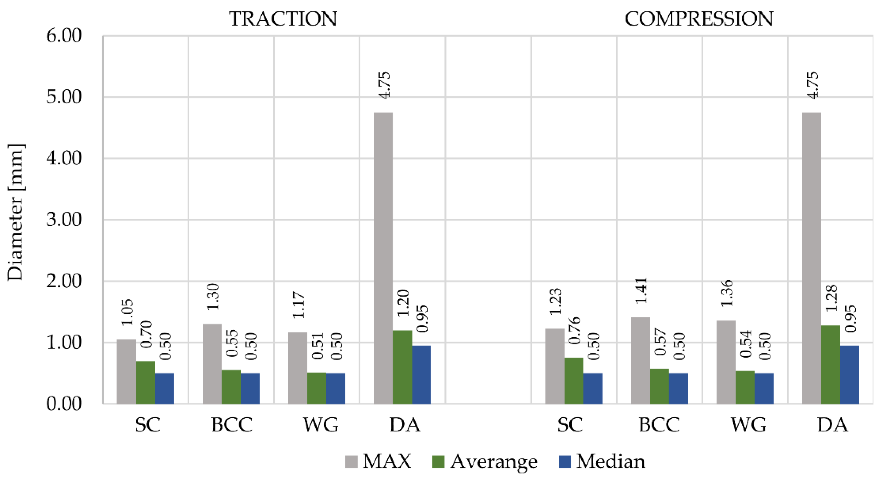
3.2. Structural Size Optimization

Figure 6 shows the size-optimized lattice structures. In both the traction and compression load cases, the optimization algorithm converged after the first iteration for the SC, BCC, and WG lattice structures, whereas it required 20 iterations for the DA structure.
The increase in the number of iterations given by the DA structure is due to the diameter variation mechanism of the algorithm, which calculates the optimized diameter based on Hooke’s equation derived for the tensional stress of a uniform bar. The stretching-dominated structures size optimization process converges immediately, as the characteristic feature of these structures is the predisposition for axial loads. Consequently, the large number of iterations required for the DA is due to the algorithm that tends to increase the size of certain beams without increasing the diameters of the surrounding ones, leading to divergence, especially in the case of bending-dominated structures, in line with previous studies [56,76].
The bar chart in Figure 7 shows that the median value of the diameters of all the configurations equals the lower diameter constraint, i.e., 0.5 mm for the SC, BCC, and WG lattices and 0.95 mm for the DA lattice; this is explained by the presence of several oversized beams that, according to the size optimization, should have a diameter smaller than the minimum allowable size, but in the final configuration present the minimum cross-section to guarantee the printability of the part. The mean value of the diameter of the SC structure is higher than the BCC and WG ones due to the lower number of beams not aligned to the load direction. The DA lattice structure is the only one that requires beams with a cross-section as high as the upper manufacturing constraint, i.e., 4.75 mm.
Figure 8 shows the values of the slenderness ratio and the relative density of the structures. The relative density is calculated through the Karamba3D plug-in, which does not consider the nodal connection between the beams, overestimating the value. The presence of a high number of oversized beams (beams with the minimum manufacturable diameter, i.e., 0.5 mm, even though the optimized size would be lower) affects the relative density of the structures with a stretching-dominated behavior, namely the SC, the BCC, and WG, which increases according to the total number of elements. Moreover, due to Maxwell’s criterion, the BCC and WG structures are over-constrained, whereas the SC and DA structures are under-constrained; this reflects on the different ways the lattices react when changing the load case.
Moving from the traction to the compression load case, the relative density of the BCC and WG increases by about 13%, whereas the relative density of the SC and DA increases by about 24%. Even if the cell size of the DA structure is 67% bigger than the others, due to the number of cells in the X-direction, this structure presents the lowest minimum slenderness ratio, 0.85 and 0.67 for the traction and compression load case, due to the bending-dominated behavior. As previously said, it is not advised to apply the beam theory when dealing with low values of slenderness ratio [77], and consequently, the results related to DA could be meaningless. This, together with the objective of maintaining the aspect ratio of the cell, led to keeping a low number of cells for the DA structure. On the opposite, since the overall maximum slenderness ratio is a low value of 13.16, the lattices are unaffected from the instability issues, having, therefore, a high Euler’s critical buckling load [78].

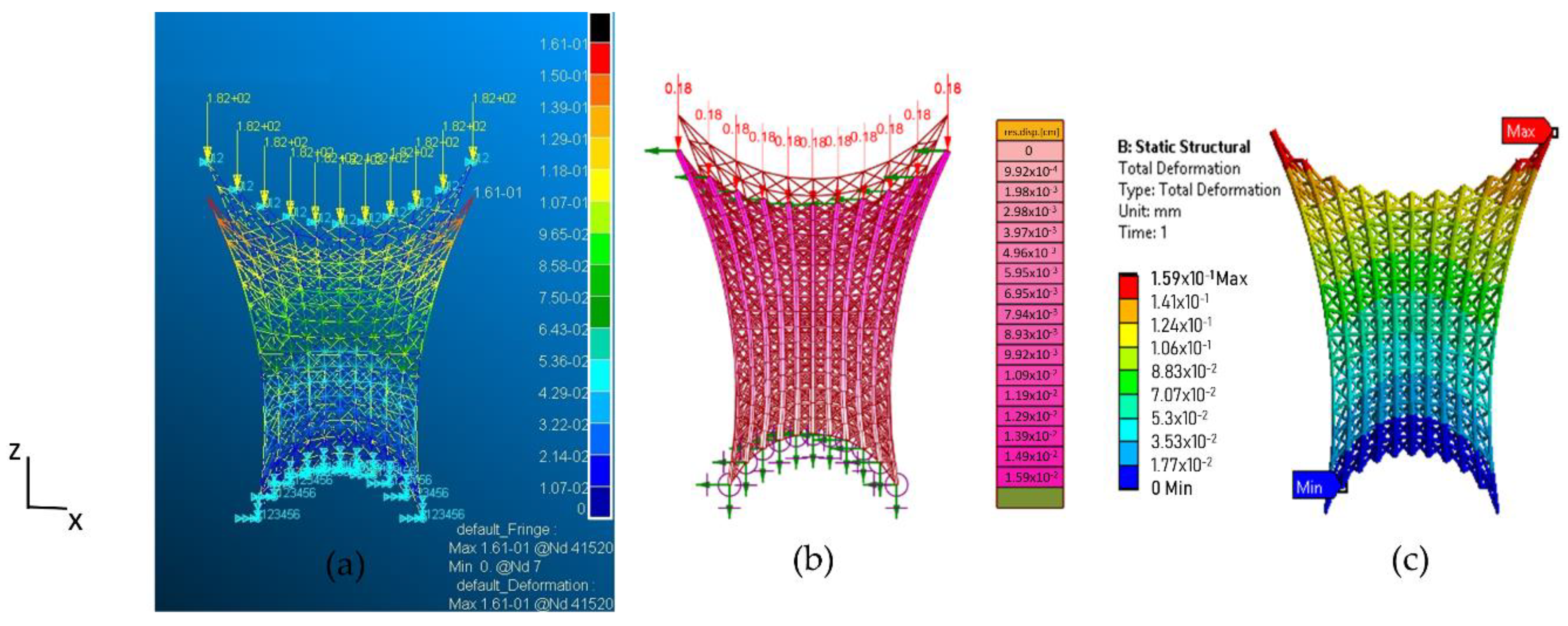
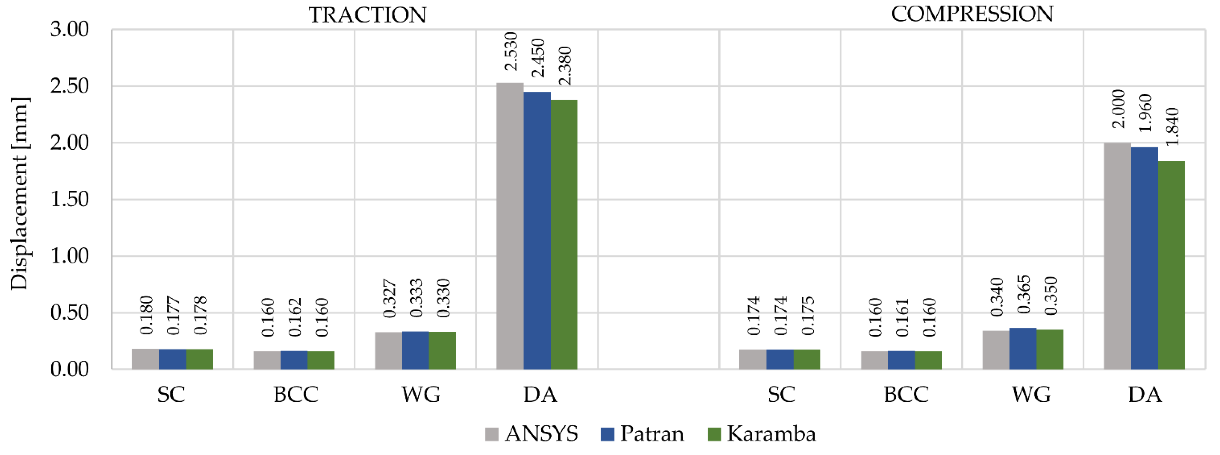
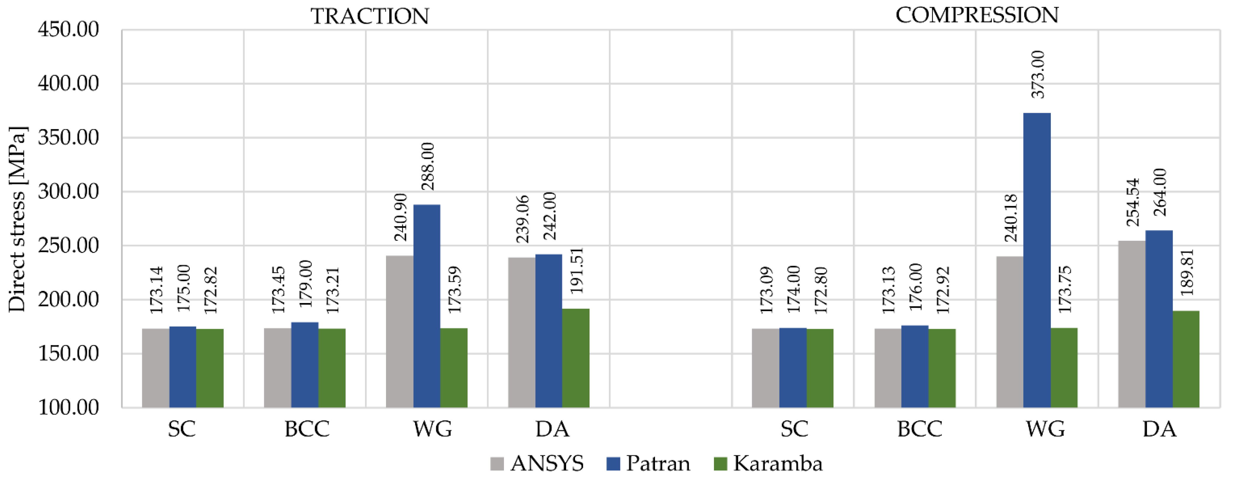
3.3. Structural Analysis Validation

In this section, the structural analyses results are presented. Figure 9 shows the simulation environments of the three FEM software for the BBC lattice structure during the compression load case (−10 kN). As previously discussed, the boundary conditions consist in locking the displacements along the X- and Y-direction of the nodes of the beams connected to the big rod’s end and locking the displacements and rotations of the nodes of the beams connected to the small rod’s end.
Figure 10 shows the maximum displacement along the Z-direction. The displacement results given by the three software are similar because, in the FE displacement-based type, the displacement is more accurate than the strain field [77]. A bending-dominated structure experiences the bending of its struts, whereas a stretching-dominated structure deforms primarily by the stretching or compressing of individual struts under loading. So, as can be seen from the results, the BC, BCC, and WG structures present a stretching-dominated behavior, whereas the DA has a bending-dominated behavior. According to the connectivity of the structure and Maxwell’s law, the BC structure should be bending-dominated but appears to be the stiffest structure between the four. The BC structure shows a stretching-dominated behavior because it is mainly stressed along the main axes; different boundary conditions would lead to a different behavior [5]. The BCC and DA structures confirm Maxwell’s rule prediction; indeed, even if they have a similar apparent density, the displacement of the DA structure is more than 10 times higher than the displacement of the BC one. Since the SC and the BCC structures come from the same unit cell, they exhibit similar mechanical behavior; the BCC is more constrained and therefore has a smaller deflection in both the load cases.
Figure 11 represents the maximum direct stress of the structures. The values of the WG and DA lattice structures from the three FE software disagree, most likely due to the very small size of the elements for the WG structure and the very small slenderness ratio for the DA one. A divergence of the results due to the small ratios of slenderness was also observed by Ptochos and Ahmadi [44,79]. For thicker beams, the shear and rotational inertia effects, which are taken into account in the Timoshenko theory but are neglected in the Euler–Bernoulli theory, start to play an important role; the shear and rotational inertia effects cause the beam to be less stiff, explaining a higher elastic modulus calculated using the Euler–Bernoulli rather than the solution based on the Timoshenko beam theory [43,46,73].
The difference between the results of Ansys and Karamba3D could be explained by the shear locking phenomenon that occurs where the application of the linear shape function leads to an over-stiffened element. To avoid this issue, the element can be subdivided into more instances, or the shape function can be changed with a quadratic or cubic one [46]. The element used in Ansys has a quadratic shape function, with an additional interpolation point in the center of the beam with respect to the Karamba3D linear element, and this could explain the difference between the direct stress result.
Indeed, from the traction to the compression configuration, an increase in the diameter is observed with a consequent decrease in the minimum slenderness ratio, causing higher divergence between the FEM results. Therefore, a limitation of the application of the beam structural analysis inside FEM software is the assumption that the elements have a minimum slenderness ratio; the results of these analyses show that for slenderness ratios lower than 2.4, the solutions between the various structural analysis tools begin to diverge. Otherwise, mechanical validation methods for lattice structures with thick beams require experimental analyses or FEM simulations involving solid elements. As a drawback, those alternatives are expected to require high costs for manufacturing the specimens, difficulties to test components with complex shapes by standard testing protocols, high computational power, and difficulties in the meshing process. Furthermore, the homogenization method cannot be performed on conformal lattice structures since they are anisotropic and have different mechanical properties along with different directions. Moreover, the actual beam joints’ stiffness due to the beams overlapping was not evaluated; this lack could lead to the underestimation of the stiffness of the model, giving an under-evaluation of the stiffness if compared to the experimental results and FE analysis based on solid elements [34,51,80]. Both the mono-dimensional beam approaches and the solid element approaches do not include manufacturing irregularities of the beam size, which negatively affect the mechanical proprieties of the entire printed lattice structure [43,48].
To prevent manufacturing issues, the beam inclination angle relative to the printing direction, also referred to as the overhang angle, and the minimum and maximum diameter of the beams are factors that must be considered. The overhang angle is suggested to be greater than 30° for avoiding loss of powder, which could lead to a partially melted zone compared to a vertical beam causing different thermal conditions that may create unique microstructures and highly irregular surface morphology [11,81]. To avoid the need for supports for the lattice structure, which would result difficult to be removed, the lattice structures could be angled for production, but it is not possible to define an ideal printing orientation due to the variable orientation of the conformal lattice. Nevertheless, recent studies have shown that small sizes of the beam may not require the use of supports [82,83], so considering the size of the beams of the studied lattice structures, it might be possible to produce them vertically by SLM technologies.

4. Conclusions

In this manuscript, the modeling, size optimization, and structural linear analysis of conformal lattice structures were presented. In particular, the work aimed to provide design tools that require a low process time and low computational power in a preliminary design phase, thanks to the implementation of the design, optimization, and geometric modeling in a single environment and to the 1D analysis that is faster than solid FEA. A geometric design approach based on the deformation of the wireframe of a regular lattice structure through the NURBS-FFD method was proposed. The possibility of performing size optimization and structural linear analysis based on the beam theory in the same environment was explored. An automated process was then developed for importing the geometrical information and constructing FE models inside the Patran/Nastran and Ansys commercial FEA software. This method promotes the design, optimization, and structural analysis of conformal cellular structures and facilitates further real-time geometrical modification through the control points of the NURBS-FFD control volume inside the same environment. At the same time, limitations are still present; the NURBS-FFD approach offers a fixed topology of the control volume, and the graphic interface can appear confusing when dealing with volumes described by many control points. Furthermore, the proposed size optimization approach and the validation methods are limited to beam-based lattice structures with a restriction on the minimum slenderness ratio.
As a case study, the central part of a piston rod was filled with four different lattice structures, based on the SC, BCC, WG, and DA unit cells, two of them with thick struts to highlight the limitation of the beam structural size optimization and structural linear analysis. It was shown how bending behavior in conformal lattice structures not only depends on the Maxwell criterion but also on the load direction with respect to the main axes of the cell, as was seen for the SC structure. It was highlighted that the constraints of the size optimization algorithm should include not only the size limitations of the manufacturing process but also the minimum slenderness ratio to use the beam theory correctly and the maximum slenderness ratio to prevent buckling effects. In conclusion, it is expected that for beam-based lattice structures, the beam theory tends to be more conservative than experimental results in terms of stiffness, and therefore, the solutions have an advantage in terms of safety, which can be useful in the AM field since irregularities and defects of the parts negatively affect the mechanical performance.
As future works, new case studies will be used to validate the NURBS-FFD method, and other unit cells will be introduced, such as strut-TPMS. Dealing with size optimization, the algorithm could be modified to interact with field approaches for structural optimization and other size optimization strategies. Concerning the modeling method, an enhanced version able to provide a lattice structure with smooth connections between the beams and between the lattice and the solid model is going to be developed. Finally, experimental tests for validating the numerical results are needed.

Author Contributions

Conceptualization, P.D.F., S.R., A.C., G.S., R.M., and G.C.; Formal analysis, P.D.F. and S.R.; Funding acquisition, G.S. and A.C.; Investigation, P.D.F., S.R., and D.B.B.; Methodology, P.D.F., S.R., A.C., D.B.B., and G.S.; Supervision, A.C., G.S., G.C., R.M., and S.R.; Writing—original draft, P.D.F., and S.R.; Writing—review and editing, P.D.F., S.R., A.C., and G.S. All authors have read and agreed to the published version of the manuscript.

Funding

This work was partially funded by the Regional Operational Programme F.S.E. 2014–2020 Veneto Region and the European Regional Development Fund POR 2014–2020, project code 2105-0036-1463-2019, “Design and manufacturing by additive technologies of innovative components using functionally graded materials”, and a Ph.D. grant of Fondazione Cassa di Risparmio di Padova e Rovigo (CARIPARO).

Institutional Review Board Statement

Not applicable.

Informed Consent Statement

Not applicable.

Data Availability Statement

The raw/processed data required to reproduce these findings can be partially shared upon request.

Acknowledgments

Enginsoft manufacturing group (headquartered in Padua, Italy) for the development of the APDL code in ANSYS.

Conflicts of Interest

The authors declare no conflict of interest. The funders had no role in the design of the study, in the collection, analyses, or interpretation of data, in the writing of the manuscript, or in the decision to publish the results.

References

  1. Rosen, D.W. Computer-Aided Design for Additive Manufacturing of Cellular Structures. Comput. Des. Appl. 2007, 4, 585–594. [Google Scholar] [CrossRef]
  2. Gibson, I.; Rosen, D.; Stucker, B.; Khorasani, M. Additive Manufacturing Technologies. Addit. Manuf. Technol. 2021. [Google Scholar] [CrossRef]
  3. Ashby, M.F. Materials Selection in Mechanical Design, 4th ed.; Butterworth Heinemann: Oxford, UK, 2010; ISBN 978-1-85617-663-7. [Google Scholar]
  4. Ashby, M.F. The properties of foams and lattices. Philos. Trans. R. Soc. A Math. Phys. Eng. Sci. 2006, 364, 15–30. [Google Scholar] [CrossRef]
  5. Mueller, J.; Matlack, K.H.; Shea, K.; Daraio, C. Energy Absorption Properties of Periodic and Stochastic 3D Lattice Materials. Adv. Theory Simul. 2019, 2, 1900081. [Google Scholar] [CrossRef] [Green Version]
  6. Syam, W.P.; Jianwei, W.; Zhao, B.; Maskery, I.; Elmadih, W.; Leach, R. Design and analysis of strut-based lattice structures for vibration isolation. Precis. Eng. 2018, 52, 494–506. [Google Scholar] [CrossRef]
  7. Fleck, N.A.; Deshpande, V.S.; Ashby, M.F. Micro-architectured materials: Past, present and future. Proc. R. Soc. A Math. Phys. Eng. Sci. 2010, 466, 2495–2516. [Google Scholar] [CrossRef]
  8. Wallach, J.; Gibson, L. Mechanical behavior of a three-dimensional truss material. Int. J. Solids Struct. 2001, 38, 7181–7196. [Google Scholar] [CrossRef]
  9. Savio, G.; Rosso, S.; Meneghello, R.; Concheri, G. Geometric Modeling of Cellular Materials for Additive Manufacturing in Biomedical Field: A Review. Appl. Bionics Biomech. 2018, 2018, 1–14. [Google Scholar] [CrossRef] [PubMed] [Green Version]
  10. Pan, C.; Han, Y.; Lu, J. Design and Optimization of Lattice Structures: A Review. Appl. Sci. 2020, 10, 6374. [Google Scholar] [CrossRef]
  11. Benedetti, M.; du Plessis, A.; Ritchie, R.; Dallago, M.; Razavi, S.; Berto, F. Architected cellular materials: A review on their mechanical properties towards fatigue-tolerant design and fabrication. Mater. Sci. Eng. R Rep. 2021, 144, 100606. [Google Scholar] [CrossRef]
  12. Zhu, H.; Hobdell, J.; Windle, A. Effects of cell irregularity on the elastic properties of open-cell foams. Acta Mater. 2000, 48, 4893–4900. [Google Scholar] [CrossRef]
  13. Wu, J.; Wang, W.; Gao, X. Design and Optimization of Conforming Lattice Structures. IEEE Trans. Vis. Comput. Graph. 2021, 27, 43–56. [Google Scholar] [CrossRef] [Green Version]
  14. Dal Fabbro, P.; Rosso, S.; Ceruti, A.; Meneghello, R.; Concheri, G.; Savio, G. Conformal lattice structures: Modeling and optimization. Design Tools and Methods in Industrial Engineering II: Proceedings of the Second International Conference on Design Tools and Methods in Industrial Engineering, ADM 2021, 9–10 September 2021, Rome, Italy. Lect. Notes Mech. Eng. 2022. [Google Scholar] [CrossRef]
  15. Wang, H.; Chen, Y.; Rosen, D.W. A Hybrid Geometric Modeling Method for Large Scale Conformal Cellular Structures. In Proceedings of the International Design Engineering Technical Conferences and Computers and Information in Engineering Conference, Long Beach, CA, USA, 24–28 September 2005; Volume 47403, pp. 421–427. [Google Scholar] [CrossRef] [Green Version]
  16. Chen, Y. 3D Texture Mapping for Rapid Manufacturing. Comput. Des. Appl. 2007, 4, 761–771. [Google Scholar] [CrossRef] [Green Version]
  17. Calladine, C. Buckminster Fuller’s “Tensegrity” structures and Clerk Maxwell’s rules for the construction of stiff frames. Int. J. Solids Struct. 1978, 14, 161–172. [Google Scholar] [CrossRef]
  18. Gibson, L.J.; Ashby, M.F. Ashby, Cellular Solids; Cambridge University Press: Cambridge, UK, 1997. [Google Scholar] [CrossRef]
  19. Maconachie, T.; Leary, M.; Lozanovski, B.; Zhang, X.Z.; Qian, M.; Faruque, O.; Brandt, M. SLM lattice structures: Properties, performance, applications and challenges. Mater. Des. 2019, 183, 108137. [Google Scholar] [CrossRef]
  20. Kaur, M.; Yun, T.G.; Han, S.M.; Thomas, E.L.; Kim, W.S. 3D printed stretching-dominated micro-trusses. Mater. Des. 2017, 134, 272–280. [Google Scholar] [CrossRef]
  21. Kirsch, U. (Ed.) Problem Statement—Structural Optimization: Fundamentals and Applications; Springer: Berlin/Heidelberg, Germany, 1993; pp. 1–56. [Google Scholar]
  22. Mantovani, S.; Campo, G.; Giacalone, M. Steering column support topology optimization including lattice structure for metal additive manufacturing. Proc. Inst. Mech. Eng. Part C J. Mech. Eng. Sci. 2020, 095440622094712. [Google Scholar] [CrossRef]
  23. Bacciaglia, A.; Ceruti, A.; Liverani, A. Surface smoothing for topological optimized 3D models. Struct. Multidiscip. Optim. 2021, 64, 3453–3472. [Google Scholar] [CrossRef]
  24. nTopology. 2021. Available online: www.ntopology.com (accessed on 30 June 2021).
  25. Siemens. 2021. Available online: www.plm.automation.siemens.com/global/it/products/mechanical-design/design-for-additive-manufacture.html (accessed on 30 June 2021).
  26. Nieto, D.; Sánchez, D. Design for Additive Manufacturing: Tool Review and a Case Study. Appl. Sci. 2021, 11, 1571. [Google Scholar] [CrossRef]
  27. Thompson, M.K.; Moroni, G.; Vaneker, T.; Fadel, G.; Campbell, R.I.; Gibson, I.; Bernard, A.; Schulz, J.; Graf, P.; Ahuja, B.; et al. Design for Additive Manufacturing: Trends, opportunities, considerations, and constraints. CIRP Ann. 2016, 65, 737–760. [Google Scholar] [CrossRef] [Green Version]
  28. Pasko, A.; Fryazinov, O.; Vilbrandt, T.; Fayolle, P.-A.; Adzhiev, V. Procedural function-based modelling of volumetric microstructures. Graph. Model. 2011, 73, 165–181. [Google Scholar] [CrossRef] [Green Version]
  29. Sola, A.; Defanti, S.; Mantovani, S.; Merulla, A.; Denti, L. Technological Feasibility of Lattice Materials by Laser-Based Powder Bed Fusion of A357.0. 3D Print. Addit. Manuf. 2020, 7, 1–7. [Google Scholar] [CrossRef] [Green Version]
  30. Savio, G.; Meneghello, R.; Concheri, G. Geometric modeling of lattice structures for additive manufacturing. Rapid Prototyp. J. 2018, 24, 351–360. [Google Scholar] [CrossRef]
  31. Savio, G.; Meneghello, R.; Rosso, S.; Concheri, G. 3D Model Representation and Data Exchange for Additive Manufacturing. Lect. Notes Mech. Eng. 2019, 3, 412–421. [Google Scholar] [CrossRef]
  32. Liang, Y.; Zhao, F.; Yoo, D.-J.; Zheng, B. Design of conformal lattice structures using the volumetric distance field based on parametric solid models. Rapid Prototyp. J. 2020, 26, 1005–1017. [Google Scholar] [CrossRef]
  33. Nguyen, J.; Park, S.I.; Rosen, D.W.; Folgar, L.; Williams, J. Conformal lattice structure design and fabrication. In Proceedings of the 23rd Annual International Solid Freeform Fabrication Symposium—An Additive Manufacturing Conference SFF, Austin, TX, USA, 6–8 August 2012; pp. 138–161. [Google Scholar]
  34. Weeger, O.; Boddeti, N.; Yeung, S.-K.; Kaijima, S.; Dunn, M.L. Digital design and nonlinear simulation for additive manufacturing of soft lattice structures. Addit. Manuf. 2019, 25, 39–49. [Google Scholar] [CrossRef]
  35. Tamburrino, F.; Graziosi, S.; Bordegoni, M. The Design Process of Additively Manufactured Mesoscale Lattice Structures: A Review. J. Comput. Inf. Sci. Eng. 2018, 18, 040801. [Google Scholar] [CrossRef]
  36. Sederberg, T.W.; Parry, S.R. Free-form deformation of solid geometric models. In Proceedings of the 13th Annual Conference on Computer Graphics and Interactive Techniques—SIGGRAPH ’86, Dallas, TX, USA, 31 August 1986; ACM Press: New York, NY, USA, 1986; Volume 20, pp. 151–160. [Google Scholar]
  37. Coquillart, S. Extended free-form deformation: A sculpturing tool for 3D geometric modeling. In Proceedings of the 17th Annual Conference on Information Technology Education, Dallas TX, USA, 1 September 1990; ACM Press: New York, NY, USA, 1990; Volume 24, pp. 187–196. [Google Scholar]
  38. Lamousin, H.; Waggenspack, N. NURBS-based free-form deformations. IEEE Eng. Med. Boil. Mag. 1994, 14, 59–65. [Google Scholar] [CrossRef]
  39. Proch, J. Free Form Deformation Methods—The Theory and Practice. In Proceedings of the 16th Conference on Applied Mathematics-APLIMAT 2017, Bratislava, Slovak republic, 31 January–2 February 2017. [Google Scholar]
  40. Zhang, Y.; Zheng, J.; Cai, Y. Proxy-driven free-form deformation by topology-adjustable control lattice. Comput. Graph. 2020, 89, 167–177. [Google Scholar] [CrossRef]
  41. Kalamkarov, A.L.; Andrianov, I.V.; Danishevskyy, V. Asymptotic Homogenization of Composite Materials and Structures. Appl. Mech. Rev. 2009, 62, 030802. [Google Scholar] [CrossRef]
  42. Savio, G.; Curtarello, A.; Rosso, S.; Meneghello, R.; Concheri, G. Homogenization driven design of lightweight structures for additive manufacturing. Int. J. Interact. Des. Manuf. 2019, 13, 263–276. [Google Scholar] [CrossRef]
  43. Ahmadi, S.; Campoli, G.; Yavari, S.A.; Sajadi, B.; Wauthle, R.; Schrooten, J.; Weinans, H.; Zadpoor, A.A. Mechanical behavior of regular open-cell porous biomaterials made of diamond lattice unit cells. J. Mech. Behav. Biomed. Mater. 2014, 34, 106–115. [Google Scholar] [CrossRef]
  44. Ptochos, E.; Labeas, G. Elastic modulus and Poisson’s ratio determination of micro-lattice cellular structures by analytical, numerical and homogenisation methods. J. Sandw. Struct. Mater. 2012, 14, 597–626. [Google Scholar] [CrossRef]
  45. Bacciaglia, A.; Ceruti, A.; Liverani, A. A systematic review of voxelization method in additive manufacturing. Mech. Ind. 2019, 20, 630. [Google Scholar] [CrossRef] [Green Version]
  46. Rakowski, J. The interpretation of the shear locking in beam elements. Comput. Struct. 1990, 37, 769–776. [Google Scholar] [CrossRef]
  47. Bacciaglia, A.; Ceruti, A.; Liverani, A. Structural Analysis of Voxel-Based Lattices Using 1D Approach. 3D Print. Addit. Manuf. 2021. [Google Scholar] [CrossRef]
  48. Ravari, M.K.; Kadkhodaei, M.; Badrossamay, M.; Rezaei, R. Numerical investigation on mechanical properties of cellular lattice structures fabricated by fused deposition modeling. Int. J. Mech. Sci. 2014, 88, 154–161. [Google Scholar] [CrossRef]
  49. Campoli, G.; Borleffs, M.; Yavari, S.A.; Wauthle, R.; Weinans, H.; Zadpoor, A.A. Mechanical properties of open-cell metallic biomaterials manufactured using additive manufacturing. Mater. Des. 2013, 49, 957–965. [Google Scholar] [CrossRef]
  50. Genovese, K.; Leeflang, S.; Zadpoor, A.A. Microscopic full-field three-dimensional strain measurement during the mechanical testing of additively manufactured porous biomaterials. J. Mech. Behav. Biomed. Mater. 2017, 69, 327–341. [Google Scholar] [CrossRef]
  51. Dong, G.; Zhao, Y.F. Numerical and experimental investigation of the joint stiffness in lattice structures fabricated by additive manufacturing. Int. J. Mech. Sci. 2018, 148, 475–485. [Google Scholar] [CrossRef]
  52. Jin, X.; Li, G.-X.; Zhang, M. Design and optimization of nonuniform cellular structures. Proc. Inst. Mech. Eng. Part C J. Mech. Eng. Sci. 2017, 232, 1280–1293. [Google Scholar] [CrossRef]
  53. Concli, F.; Gilioli, A. Numerical and experimental assessment of the mechanical properties of 3D printed 18-Ni300 steel trabecular structures produced by Selective Laser Melting—A lean design approach. Virtual Phys. Prototyp. 2019, 14, 267–276. [Google Scholar] [CrossRef]
  54. Rosso, S.; Savio, G.; Uriati, F.; Meneghello, R.; Concheri, G. Optimization Approaches in Design for Additive Manufacturing. Proc. Des. Soc. Int. Conf. Eng. Des. 2019, 1, 809–818. [Google Scholar] [CrossRef] [Green Version]
  55. Rosso, S.; Uriati, F.; Grigolato, L.; Meneghello, R.; Concheri, G.; Savio, G. An Optimization Workflow in Design for Additive Manufacturing. Appl. Sci. 2021, 11, 2572. [Google Scholar] [CrossRef]
  56. Savio, G.; Gaggi, F.; Meneghello, R.; Concheri, G. Design method and taxonomy of optimized regular cellular structures for additive manufacturing technologies. In Proceedings of the 20th International Conference on Engineering Design (ICED 15), Milan, Italy, 27–30 July 2015; pp. 235–244. Available online: https://www.designsociety.org/publication/37788/design_method_and_taxonomy_of_optimized_regular_cellular_structures_for_additive_manufacturing_technologies (accessed on 29 November 2021).
  57. Preisinger, C. Linking Structure and Parametric Geometry. Arch. Des. 2013, 83, 110–113. [Google Scholar] [CrossRef]
  58. BSI. Bs en 1993-1-1: 2005: Eurocode 3. design of steel structures. general rules and rules for buildings, European Committee for Standardization, Brussel, BE, 2005. Available online: https://www.phd.eng.br/wp-content/uploads/2015/12/en.1993.1.1.2005.pdf (accessed on 29 November 2021).
  59. ISO/ASTM 52900:2015. Additive Manufacturing-General Principles-Terminology; ISO International Organization for Standardization: Geneva, Switzerland; ASTM American Society for Testing and Materials: West Conshohocken, PA, USA, 2015. [Google Scholar]
  60. Yap, C.Y.; Chua, C.K.; Dong, Z.; Liu, Z.H.; Zhang, D.Q.; Loh, L.E.; Sing, S.L. Review of selective laser melting: Materials and applications. Appl. Phys. Rev. 2015, 2, 041101. [Google Scholar] [CrossRef]
  61. Frazier, W.E. Metal Additive Manufacturing: A Review. J. Mater. Eng. Perform. 2014, 23, 1917–1928. [Google Scholar] [CrossRef]
  62. Wohlers, I.; Campbell, O.; Diegel, J.; Kowen, T. Caffrey, Wohlers Report 2019; Wohlers Associates, Inc.: Fort Collins, CO, USA, 2019; ISBN 978-0-9913332-5-7. [Google Scholar]
  63. Renishaw, AlSi10Mg-0403 Powder for Additive Manufacturing. 2015. Available online: www.renishaw.it/it/schede-tecniche-produzione-additiva--17862 (accessed on 29 November 2021).
  64. Weaver, J.M.; Barton, T.; Linn, J.; Jenkins, D.; Miles, M.P.; Smith, R. Quantifying accuracy of a concept laser metal additive machine through the NIST test artifact. Rapid Prototyp. J. 2019, 25, 221–231. [Google Scholar] [CrossRef]
  65. Mäenpää, J. Algorithm-Aided Structural Engineering of Steel-Framed Warehouse. Master’s Thesis, Tampere University of Technology, Tampere, Finland, January 2018. [Google Scholar]
  66. Wang, C. Timoshenko Beam-Bending Solutions in Terms of Euler-Bernoulli Solutions. J. Eng. Mech. 1995, 121, 763–765. [Google Scholar] [CrossRef]
  67. Madenci, E.; Özkılıç, Y.O.; Gemi, L. Buckling and free vibration analyses of pultruded GFRP laminated composites: Experimental, numerical and analytical investigations. Compos. Struct. 2020, 254, 112806. [Google Scholar] [CrossRef]
  68. Khdeir, A.; Reddy, J. Free vibration of cross-ply laminated beams with arbitrary boundary conditions. Int. J. Eng. Sci. 1994, 32, 1971–1980. [Google Scholar] [CrossRef]
  69. Gemi, L.; Madenci, E.; Özkılıç, Y.O. Experimental, analytical and numerical investigation of pultruded GFRP composite beams infilled with hybrid FRP reinforced concrete. Eng. Struct. 2021, 244, 112790. [Google Scholar] [CrossRef]
  70. Wang, X.D.; Shi, G. Boundary Layer Solutions Induced by Displacement Boundary Conditions of Shear Deformable Beams and Accuracy Study of Several Higher-Order Beam Theories. J. Eng. Mech. 2012, 138, 1388–1399. [Google Scholar] [CrossRef]
  71. Madenci, E.; Gülcü, Ş. Optimization of flexure stiffness of FGM beams via artificial neural networks by mixed FEM. Struct. Eng. Mech. 2020, 75, 633–642. [Google Scholar] [CrossRef]
  72. Madenci, E. Free vibration analysis of carbon nanotube RC nanobeams with variational approaches. Adv. Nano Res. 2021, 11, 157–171. [Google Scholar]
  73. ANSYS. ANSYS Help. 2021. Available online: https://ansyshelp.ansys.com/account/secured?returnurl=/Views/Secured/corp/v190/wb_sim/ds_Beam_Tool.html?q=beam tool (accessed on 30 June 2021).
  74. Preisinger, C. Karamba3D Manual. 2021. Available online: https://manual.karamba3d.com/3-in-depth-component-reference/3.6-results/3.6.6-utilization-of-elements (accessed on 30 June 2021).
  75. Guo, X.; Zheng, X.; Yang, Y.; Yang, X.; Yi, Y. Mechanical behavior of TPMS-based scaffolds: A comparison between minimal surfaces and their lattice structures, SN. Appl. Sci. 2019, 1, 1–11. [Google Scholar] [CrossRef] [Green Version]
  76. Savio, G.; Meneghello, R.; Concheri, G. Optimization of lattice structures for additive manufacturing technologies, Advances on Mechanics, Design Engineering and Manufacturing. Lect. Notes Mech. Eng. 2017, 213–222. [Google Scholar] [CrossRef]
  77. Zienkiewicz, O.C.; Taylor, R.L.; Zhu, J.Z. The Finite Element Method: Its Basics and Foundamentals, 7th ed.; Butterworth Heinemann: Oxford, UK, 2013; ISBN 9780080951355. [Google Scholar]
  78. Desai, P. Effect of Slenderness Ratio on Euler Critical Load for Elastic Columns with Effect of Slenderness Ratio on Euler Critical Load for Elastic Columns with ANSYS. J. Eng. Res. Appl. 2018, 8, 40–43. [Google Scholar] [CrossRef]
  79. Ahmadi, S.M.; Yavari, S.A.; Wauthle, R.; Pouran, B.; Schrooten, J.; Weinans, H.; Zadpoor, A.A. Additively Manufactured Open-Cell Porous Biomaterials Made from Six Different Space-Filling Unit Cells: The Mechanical and Morphological Properties. Materials 2015, 8, 1871–1896. [Google Scholar] [CrossRef] [PubMed] [Green Version]
  80. Jamshidian, M.; Boddeti, N.; Rosen, D.; Weeger, O. Multiscale modelling of soft lattice metamaterials: Micromechanical nonlinear buckling analysis, experimental verification, and macroscale constitutive behaviour. Int. J. Mech. Sci. 2020, 188, 105956. [Google Scholar] [CrossRef]
  81. Yan, C.; Hao, L.; Hussein, A.; Young, P.; Raymont, D. Advanced lightweight 316L stainless steel cellular lattice structures fabricated via selective laser melting. Mater. Des. 2014, 55, 533–541. [Google Scholar] [CrossRef] [Green Version]
  82. Hossain, U.; Ghouse, S.; Nai, K.; Jeffers, J.R. Mechanical and morphological properties of additively manufactured SS316L and Ti6Al4V micro-struts as a function of build angle. Addit. Manuf. 2021, 46, 102050. [Google Scholar] [CrossRef] [PubMed]
  83. Rosso, S.; Meneghello, R.; Concheri, G.; Savio, G. Scale and Shape Effects on the Fatigue Behaviour of Additively Manufactured SS316L Structures: A Preliminary Study. In Lecure notes in Mechanical Engineering. Design Tools and Methods in Industrial Engineering. Proceedings of the International Conference on Design Tools and Methods in Industrial Engineering, ADM 2019, 9–10 September 2019, Modena, Italy. Lect. Notes Mech. Eng. 2020, 879–890. [Google Scholar] [CrossRef]
Figure 1. Front view (a), side view (b), and perspective view (c) of the piston rod.
Applsci 11 11449 g001
Figure 2. Unit cell geometry: simple cubic (SC), body-centered cubic (BCC), modified Wallach-Gibson (WG), and diamond (DA).
Applsci 11 11449 g002
Figure 3. NURBS-FFD approach applied to the diamond lattice structure (green lines) (a) via a control cage (red lines) (b) to conform the lattice to the design space (black lines) (c).
Applsci 11 11449 g003
Figure 4. Boundary condition of the traction load case: (a) Karamba3D, (b) Nastran, and (c) ANSYS Mechanical.
Applsci 11 11449 g004
Figure 5. Conformal wireframe obtained by the NURBS-FFD modeling method.
Applsci 11 11449 g005
Figure 6. Optimized lattice structures for the compression load case inside Rhinoceros 7 design environment.
Applsci 11 11449 g006
Figure 7. Overall results from the size optimization of the four lattice structures: maximum, average, and median diameter for traction and the compression load cases.
Applsci 11 11449 g007
Figure 8. Overall results from the size optimization of the four lattice structures: slenderness ratio and relative density for the traction and the compression load cases.
Applsci 11 11449 g008
Figure 9. FEA deformation results for the BBC lattice structure during the compression load case. Deformation scale: 40 times. (a) MSC Patran/Nastran, (b) Karamba3D, and (c) ANSYS Mechanical.
Applsci 11 11449 g009
Figure 10. Displacement results of the traction and the compression load cases, according to the FEM software.
Applsci 11 11449 g010
Figure 11. Direct stress results of the traction and the compression load cases, according to the FEM software.
Applsci 11 11449 g011
Table 1. Load information for each lattice structure.
Lattice Structure TypeNumber of
Loaded Nodes
Traction Load
(for Each Node) [N]
Compression Load
(for Each Node) [N]
SC55136.36−181.82
BCC55136.36−181.82
WG9479.79−106.38
DA20375.00−500.00
Table 2. Material properties of AlSi10Mg produced by SLM technology [63].
Density2700 Kg/m3
Young modulus68 GPa
Yield strength190 MPa
Ultimate tensile strength335 MPa
Poisson ratio0.30
Table 3. Geometric information of the wireframes and Maxwell law results.
Lattice Structure TypeNumber of NodesNumber of BeamsTotal Beams
Length [m]
Maxwell’s Rule
SC88021417.86Bending-dominated
BCC1480693723.27Stretching-dominated
WG384118,12448.22Stretching-dominated
DA62310783.96Bending-dominated
Publisher’s Note: MDPI stays neutral with regard to jurisdictional claims in published maps and institutional affiliations.

