Article

An Air Spring Vibration Isolator Based on a Negative-Stiffness Structure for Vehicle Seat

School of Mechanical and Automotive Engineering, University of Ulsan, Daehakro 93, Nam-gu, Ulsan 44610, Korea
*
Author to whom correspondence should be addressed.
Appl. Sci. 2021, 11(23), 11539; https://doi.org/10.3390/app112311539
Submission received: 3 November 2021 / Revised: 2 December 2021 / Accepted: 3 December 2021 / Published: 6 December 2021

Abstract

:
This research introduces an air spring vibration isolator system (ASVIS) based on a negative-stiffness structure (NSS) to improve the vehicle seat’s vibration isolation performance at low excitation frequencies. The main feature of the ASVIS consists of two symmetric bellows-type air springs which were designed on the basis of a negative stiffness mechanism. In addition, a crisscross structure with two straight bars was also used as the supporting legs to provide the nonlinear characteristics with NSS. Moreover, instead of using a vertical mechanical spring, a sleeve-type air spring was employed to provide positive stiffness. As a result, as the weight of the driver varies, the dynamic stiffness of the ASVIS can be easily adjusted and controlled. Next, the effects of the dimension parameters on the nonlinear force and nonlinear stiffness of ASVIS were analyzed. A design process for the ASVIS is provided based on the analytical results in order to achieve high static–low dynamic stiffness. Finally, numerical simulations were performed to evaluate the effectiveness of the ASVIS. The results obtained in this paper show that the values of the seat displacement of the ASVIS with NSS were reduced by 77.16% in comparison with those obtained with the traditional air spring isolator without NSS, which indicates that the design of the ASVIS isolator with NSS allows the effective isolation of vibrations in the low-frequency region.

1. Introduction

Usually, whole-body vibration is associated with vehicle movement, which can affect the comfort, performance, and health of the driver [1,2]. The human body responds strongly to vertical whole-body vibration at frequencies ranging from 0.5 to 5 Hz, which are below 2 Hz in horizontal axes [3,4]. In order to increase the driver’s comfort, safety, and health by reducing weariness caused by extended hours of driving or exposure to adverse road conditions, a low-frequency vibration isolator is developed by combining a positive stiffness element with a negative stiffness element.
The traditional linear isolator model, which is frequently used to demonstrate vibration isolation, consists of a linear stiffness spring combined with a damper (spring–mass–damper system) [5,6,7]. Only when the excitation frequency exceeds 2 times the natural frequency of the system can these structures achieve efficient vibration isolation. On the other hand, when the excitation frequency is less than 2 times the natural frequency, the vibration of the driver’s seat is increased in comparison with that of the base excitation [8]. This proves that the traditional vibration isolation systems can have a satisfying performance only at high-frequency excitation but not at low-frequency excitation.
To solve this problem, vibration isolation systems with NSS have been recommended to overcome the disadvantages of classical linear isolation, which can effectively isolate vibrations in the low-frequency region while maintaining load capacity and low dynamic stiffness. In an early study by Alabuzhev et al. [9], the NSS vibration isolator comprised two horizontal springs connected to the load via an actuator joint to produce negative stiffness. Platus et al. [10] suggested a negative stiffness mechanism based on two rigid bars hinged in the middle, supported on pivots at their outer ends and loaded in compression by opposing forces. Danh et al. [11] continued to study this mechanism and developed a vibration isolator with NSS that employed two horizontal springs connected to the load via sliders and inclined links. The mechanical characteristics and experimental prototype of the proposed system were also analyzed. Later, these researchers applied an adaptive backstepping controller to enhance the isolation effectiveness of the vibration isolator system with NSS [12]. A nonlinear vibration isolation system with an NSS was investigated in terms of dynamics and power flow by J. Yang et al. [13]. Shi et al. [14] suggested to use a novel spring bar mechanism to improve the vibration isolation performance of the NSS. Moreover, other researchers designed vibration isolation systems that used a cam–roller mechanism combined with negative-stiffness elements [15]. Yao et al. [16] proposed a negative stiffness vibration isolator based on a cam–roller–spring mechanism with a custom-designed cam profile. Other designs that produced negative stiffness characteristics include a magnet spring structure by Zheng et al. [17] and a pneumatic negative-stiffness mechanism introduced by Palomares et al. [18]. Since the negative stiffness mechanism has very little load capacity, it can only operate well when connected in parallel with a positive-stiffness element.
By combining a negative-stiffness element with a positive-stiffness element in parallel, a quasi-zero-stiffness (QZS) vibration isolation system achieved both high static stiffness and low dynamic stiffness around the equilibrium position. Carrella et al. [19] proposed a QZS vibration isolator comprising a vertical spring operating in parallel with two oblique springs. Lan et al. [20] presented the nonlinear-stiffness theoretical analysis of a QZS system with damping at the dynamic equilibrium position. The results of numerical simulations of differential equations for the QZS vibration isolator under different excitations, such as harmonic excitation, random excitation, and impulse excitation, were presented by Chang et al. [21]. The vibration isolation efficiency of the QZS system was confirmed in [22], which indicated that the response of the QZS system under harmonic force was nearly almost two times lower than that of the classical linear vibration isolator. A nonlinear inertance mechanism (NIM) was designed using a pair of oblique inerters with one common hinged terminal and the other terminals fixed [23]. In addition, Zhou et al. [24] recommended a new design of the QZS system that used a cam–roller–spring mechanism. Based on this mechanism, Ye et al. [25] further developed a QZS system with multiple frequency regions that could respond to a variety of isolated masses or applied forces. In addition, QZS vibration isolators based on linear magnetic springs [26] also attracted a attention. However, one disadvantage of the QZS vibration isolator is its limited displacement range when the stiffness is reduced to zero.
In other studies, some researchers introduced a nonlinear vibration isolator that used a scissor-like structure (SLS) to enhance the vibration isolation effectiveness. The SLS vibration isolator described by X. Sun et al. was composed of connecting horizontal springs, rods of the same length, and joints [27]. The results demonstrated that vibration isolators with an SLS can achieve good nonlinear vibration isolation performance while simultaneously overcoming the disadvantages of an existing QZS system. Inspired by the SLS presented in [27], an innovative QZS vibration isolator was constructed, adopting a single-layer SLS and parabolic cam–roller structures [28]. The proposed vibration system showed a small improvement in offset when compared to the system with only an SLS, but significantly reduced the magnitude of the vibration. In addition, a vibration isolator with SLS was developed by Wei et al. by combining an n-layer scissor-like mechanism with electromagnetic generators [29]. The results showed that the structural parameters of the suggested system may be adjusted to obtain better energy-harvesting effectiveness. According to the above-mentioned research, the SLS can provide nonlinear stiffness, which is also effective for isolating low-frequency vibration.
On the other hand, air springs are well known for their ability to easily provide variable force and load capacities by simply adjusting the gas pressure within the springs [30]. To further enhance the isolation performance of the vehicle seat, an air spring with negative stiffness was adopted as a vibration isolator of the driver’s seat by Lee et al. [31]. Danh et al. [12] constructed a pneumatic vibration isolator employing an NSS to increase the isolation performance in low-excitation frequency ranges. Moreover, Palomares et al. [18] presented an NSS vibration isolator based on a set of two pneumatic actuators originally in a horizontal position and perpendicular to a reversible sleeve air spring. According to the analytical and experimental results, the resonance frequency of this structure was reduced by up to 58%, and the transmissibility modulus was increased by up to 78%. Later, when this structure was used as a vibration isolator in vehicle seats, comfort improvements ranging from 10% to 35% were observed [32]. Hence, the pneumatic vibration isolation system based on NSS achieved vibration isolation with different masses of the isolated objects.
The important contribution of the present paper is the replacement of the traditional vibration isolator without NSS in a vehicle seat with a new vibration isolator with NSS, which consists of two air bellows combined with a crisscross mechanism to overcome the disadvantages of the classical isolator. Furthermore, a sleeve air spring was adopted to replace a positive-stiffness spring, which provided a stable support force when the load changed. Next, a mathematical model and the relationship between the nonlinear stiffness and the displacement of the ASVIS were derived. In addition, the displacement responses with respect to the time of the ASVIS were obtained by numerical simulation to evaluate the vibration isolation performance. Then, the results were compared with those of the classical air spring isolator without NSS to show the advantages of the ASVIS with NSS. Accordingly, the developed mechanical model of the ASVIS isolator and the analysis characteristics of the air springs are presented in Section 2. The mathematical model and the stability analysis of the ASVIS are investigated in Section 3. The numerical simulation results are verified and compared with those of the classical vibration isolator without NSS in Section 4. Finally, Section 5 presents the conclusions.

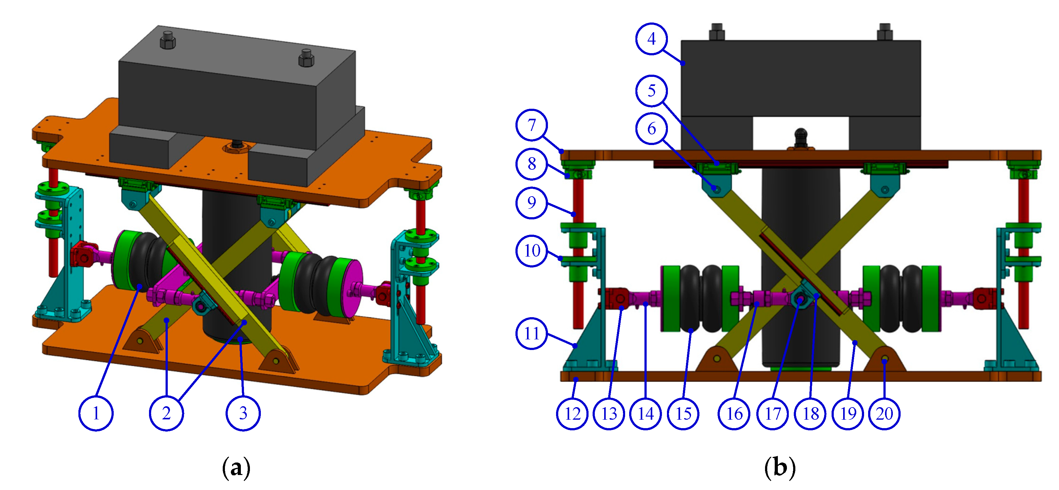
2. Design of the Air-Spring Vibration Isolator System

2.1. Model Description

The ASVIS with NSS was improved with respect to the traditional vibration isolator by employing a sleeve air spring to replace the damper and the linear spring. The general structure of the ASVIS is displayed in Figure 1a. It consists of three individual structures, namely, a bellows-type air spring with NSS (1), a crisscross mechanism (2), and a sleeve-type air spring (3). When the isolated object (4) moves vertically, the air bellows mechanism (1) combines with the crisscross mechanism (2) to provide negative stiffness along the vertical axis, while a sleeve air spring (3) provides positive stiffness.
The schematic diagram of the ASVIS in the static equilibration position is described in Figure 1b. Firstly, the isolated object (4) was fixed to the upper plate and kept stationary. Two linear shafts (9) were assembled perpendicularly to the upper plate (7) by a bracket (8), which could slip on the two linear bushings (10). The two linear bushings (10) were fitted on the base support (11) to make the upper plate (7) move only along the vertical direction. Moreover, a crisscross structure (2) comprised two straight bars (19) and loading supports in a crisscross ‘X’ pattern. The upper ends of the straight bar (19) were connected with the upper linear guide (5) via a linear support (6), while the lower ends of the straight bar (19) were connected in the same manner to the base (12). Hence, the lower ends of the straight bar (19) could rotate circularly by means of a pin (20), while the upper ends could freely slide along the surface of the upper plate (7). Furthermore, two air bellows (15) were installed between the left link (14) and the right link (16). One side of the air bellows (15) was connected with a bellows fork (13), and the other side was connected with the crisscross mechanism by using a rotating joint (17). This joint could move up and down while slipping on the bellows’ linear guide (18). Finally, a negative-stiffness structure consisted of the air bellows (15), the bellows fork (13), the left link (14), and the right link (15), which produced a negative stiffness in the vertical direction.
In addition, a sleeve air spring was also added since it could provide sufficient rigidity in static conditions and be adapted to any weight changes. As a result, the dynamic stiffness in the vertical axis of the ASVIS system was equal to the total of the dynamic stiffness of the sleeve-type air spring and the negative-stiffness structure.

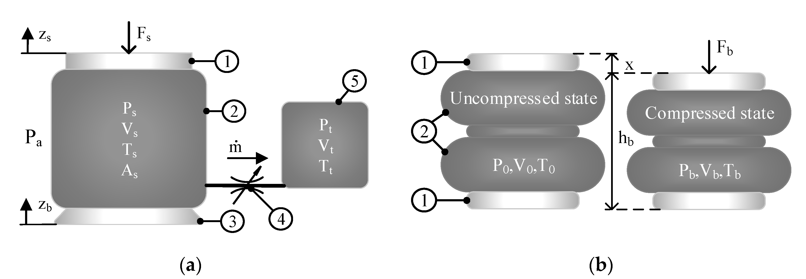
2.2. Analysis of the Characteristics of the Air Spring

Figure 2a illustrates the analytical model of a sleeve-type air spring, which includes bead plate (1), bellows (2), and piston (3) connected to an auxiliary tank (5) via an orifice (4). When the air spring is affected by the force F s , the gas inside the air spring is delivered from the air spring into the auxiliary tank. As a result, differential pressure is generated at both ends of the variable orifice, causing air to flow through the orifice and create damping and dissipating vibration energy. Hence, gas states in the sleeve-type air spring and auxiliary tank are altered, including internal air mass (kg), volume (m3), pressure (Pa), temperature (K).
The compressed air in the bellows provides the axial sleeve air spring elastic force, which is represented by
F s = ( P s P a ) A s
where P s , P a , and A s are the absolute pressure of the gas in the sleeve air spring, the atmospheric pressure, and the effective area of the sleeve air spring (which is a non-linear function of the spring height), respectively.
By using the ideal gas laws, the mass flow rate of air into the sleeve air spring is expressed as follows [33]:
m ˙ = d d t ( ρ s V s ) = ρ ˙ s V s + ρ s V ˙ s
where the variables ρ s and V s are the air density and the volume of the sleeve air spring, respectively.
The mass flow rate is positive for the air inflow to the sleeve air spring and negative while exhausting the air from the sleeve air spring. Assuming that the process of air variation in the two volumes follows a polytropic process, then the relationship between air density and internal pressure is described as follows:
P s ρ s n = P s e ρ s e n
where the variables ρ s e and P s e represent the air density and the absolute pressure in the sleeve air spring at the equilibrium position, respectively.
The constant n = C p / C v is the polytropic exponent, which is defined as the ratio of the specific heats of a gas. C p and C v are the specific heat of the gas at constant pressure and constant volume, respectively.
From the ideal gas law, the absolute pressure at equilibrium can be expressed as
P s e = ρ s e R T s e
where R and T s e are the specific gas constant and the absolute temperature at the equilibrium position, respectively.
By substituting Equation (4) into Equation (3) and differentiating with respect to time, the density of the air inside the sleeve air spring changes according to
ρ ˙ s = 1 n R T s e ( P s P s e ) 1 n n P ˙ s
By combining Equations (2) and (5), the mass flow rate is expressed as
m ˙ = 1 n R T s e ( P s P s e ) 1 n n V s P ˙ s + P s e R T s e ( P s P s e ) 1 n V ˙ s
Then, the first-order differential equation for the pressure of the air in the sleeve ai-spring can be derived:
P ˙ s = n R T s e V s ( P s P s e ) n 1 n m ˙ n P s V s V ˙ s
Expanding Equation (7) with Taylor’s series, the change in air pressure within the sleeve air spring is described by
P ˙ s = n R T s e V s e m ˙ n P s e V s e V ˙ s
Since the gas process in the auxiliary tank is identical to the gas process in the sleeve-type air spring, the differential equation for the pressure ( P t ) in the auxiliary tank is derived similarly. Assume that the volume of the auxiliary tank is not changed during the operation. Based on Equation (2), the mass flow rate into the tank is obtained as
m ˙ = ρ ˙ t V t
Hence, the differential equation for pressure in the auxiliary tank is written as
P ˙ t = n R T t V t ( P t P t e ) 1 n n m ˙
where P t and V t are the pressure and the volume in the auxiliary tank, respectively. P t e is the pressure in the tank at the equilibrium position. Note that at the equilibrium position, the mass flow rate is zero, the pressures in the sleeve air spring and the auxiliary tank are the same ( P s = P t , P s e = P t e ), and the temperatures in the sleeve air-spring and the auxiliary tank are constant and equal ( T s = T t ).
Consider a bellows-type air spring as displayed in Figure 2b. It can be shown that this spring is compressed by approximately x from its uncompressed state. By applying the first law of thermodynamics, the relationship between the force F b and the pressure on the air bellows is as follows [34]
F b = ( P b P a ) . A b
where P b is the absolute pressure in the bellows-type air spring, and A b is the effective area of the spring.
The stiffness characteristic of the bellows-type air spring can be defined as the derivative of this force with respect to the height x according to Equation (12)
K b = d F b d x = ( P b P a ) d A b d x + d ( P b P a ) d x A b
If it is assumed that the change in gas conditions is a polytrophic process, the thermodynamic state of air in the bellows is described by
P b . V b n = constant
Given the initial absolute pressure P 0 and volume V 0 , the air bellow volume V 0 at an absolute pressure P b is defined by Equation (14)
V b = V 0 ( P 0 P b ) 1 n
The derivative of the absolute pressure P b with respect to the height h can be derived from Equation (13)
d P b d x = n . P b . V b n 1 V b n d V b d x
Combining Equation (15) with Equation (12), we can obtain the air bellows stiffness:
K b = ( P b P a ) d A b d x n P b A b V b d V b d x

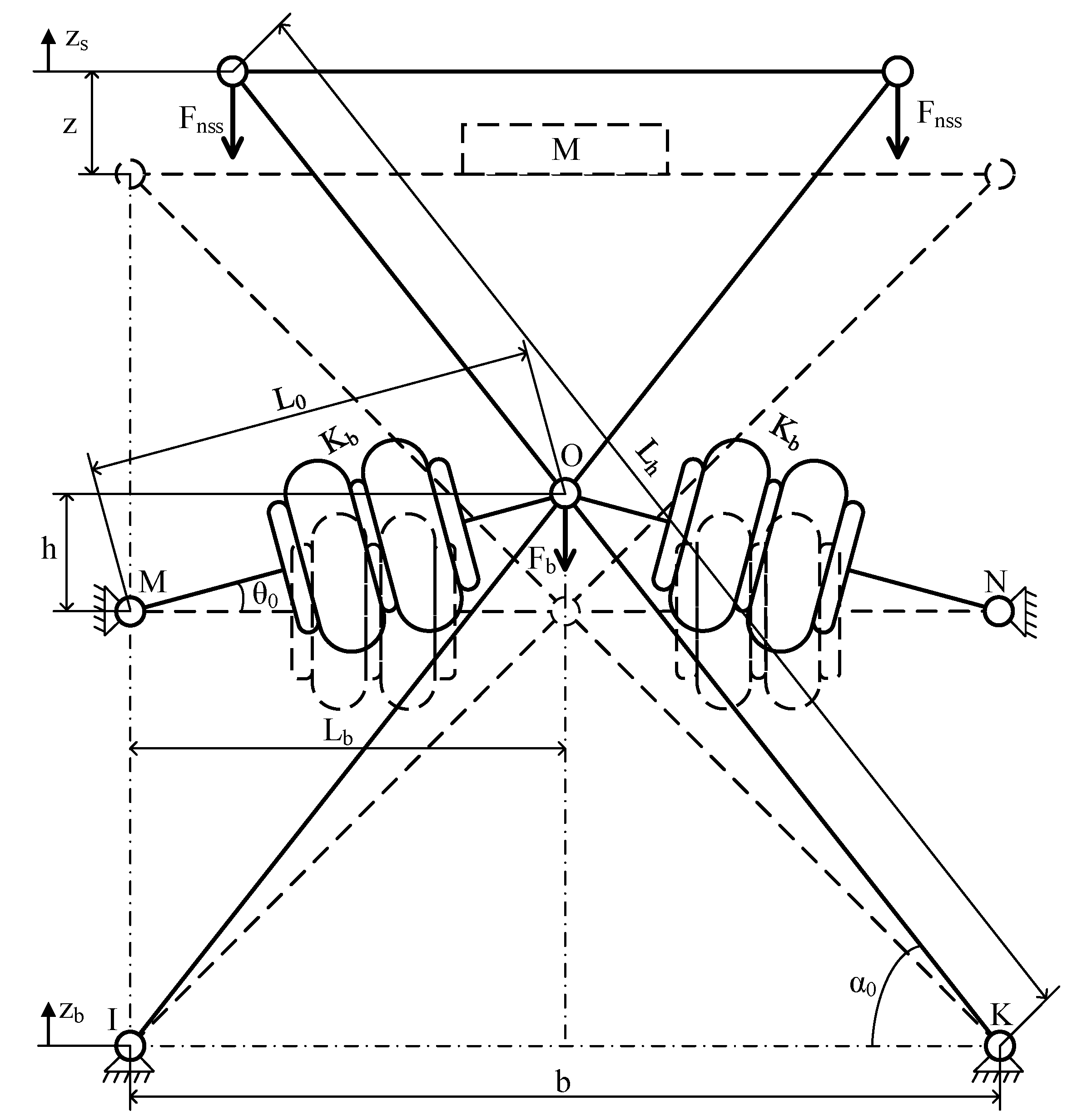
3. Stability Analysis of the Air-Spring Vibration Isolator System

We analyzed the restoring force of the ASVIS; the schematic of the crisscross structure and negative stiffness mechanism without the sleeve air spring with stiffness K s is displayed in Figure 3. The solid line indicates the initial position of the ASVIS, meaning that at this position, two bellows air springs and a sleeve air spring were uncompressed. The dashed line describes the static equilibrium position of the ASVIS when an isolated object with mass (M) is placed on the upper plate. In this diagram, z s and z b are the absolute displacements of the isolated object and the base excitation, respectively, and z is the vertical static distance between the static equilibrium position and the highest position, which corresponds to the condition with no isolated object. Moreover, L h is the length of the two straight bars of the crisscross mechanism, and α is the angle that each straight bar makes with the horizontal direction. The horizontal distance between two rotation joints at points I and K is denoted by the symbol b. Two bellows-type air springs, which are initially located at an angle θ 0 from the horizontal direction, have a stiffness K b at points M and N. A force F b is exerted by the bellows-type spring on point O, which is horizontally distanced L b from the points M and N, while initially located at a height h from these points.
Based on the geometrical relationships in the crisscross structure, the static distance z caused by mass M is obtained as
z = 2 h ( b L h cos α ) tan α
The increment of the length of the bellows-type air spring can be written as
Δ L b = L 0 L b = h 2 + L b 2 L b
where L 0 is the length of the bellows-type air spring in an uncompressed state, and L b is its length in the static equilibrium position.
The force provided by the bellows-type air spring F b is derived as
F b = 2 K b Δ L b sin θ
where K b is the stiffness of the spring, and sin θ = h / h 2 + L b 2 .
We can describe Equation (19) as follows
F b = 2 K b h ( 1 L b h 2 + L b 2 )
In the vertical direction, the total force F n s s supplied by the bellows-type air spring can be expressed by
F n s s = 2 F b cos α / cos α 0
where cos α 0 = b / L h is the initial angle of a straight bar with the horizontal direction.
Substituting Equations (17) and (20) into Equation (21), the general equation for the relationship between force F n s s and distance z in the vertical direction is as follows:
F n s s = ( 2 K b cos α ( z + ( b L h cos α ) tan α ) cos α 0 ) ( 1 L b ( z + ( b L h cos α ) tan α 2 ) 2 + L b 2 )
The dimensionless parameters are defined as follows
F ^ n s s = F n s s K b L b ;   z ^ = z L b ;   L ^ h = L h L b   and   b ^ = b L b
where F ^ n s s , z ^ , L ^ h , and b ^ are the non-dimensional restoring force, the non-dimensional distance of z, the non-dimensional length of the straight bar L h , and the non-dimensional distance of b, respectively.
Replacing z ^ , L ^ h , and b ^ into Equation (22), the non-dimensional restoring force of the ASVIS can be written as
F ^ n s s = ( 2 cos α ( z ^ + ( b ^ L ^ h cos α ) tan α ) cos α 0 ) ( 1 1 ( z ^ + ( b ^ L ^ h cos α ) tan α 2 ) 2 + 1 )
Differentiating Equation (22) with respect to the distance z yields the stiffness of the ASVIS as follows
K n s s = 2 K b cos α cos α 0 ( 1 L b ( z + ( b L h cos α ) tan α 2 ) 2 + L b 2 + L b 2 ( z + ( b L h cos α ) tan α ) 2 ( ( z + ( b L h cos α ) tan α 2 ) 2 + L b 2 ) 3 )
The non-dimensional stiffness K ^ n s s = K n s s / K b L b can be expressed as
K ^ n s s = 2 cos α cos α 0 ( 1 1 ( z ^ + ( b ^ L ^ h cos α ) tan α 2 ) 2 + L ^ b 2 + 1 2 ( z ^ + ( b ^ L ^ h cos α ) tan α ) 2 ( ( z ^ + ( b ^ L ^ h cos α ) tan α 2 ) 2 + L ^ b 2 ) 3 )
For the NSS and crisscross structure in Figure 3, the sleeve-type air spring K s is in parallel with the vertical components of the bellows-type air spring. The reaction force of the sleeve-type air spring is given by
F s = K s z
The equivalent force of the ASVIS can be written as
F e q = F s + 2 F n s s
The non-dimensional equivalent force of the ASVIS is obtained as
F ^ e q = z ^ + ( 2 K ^ b s cos α ( z ^ + ( b ^ L ^ h cos α ) tan α ) cos α 0 ) ( 1 1 ( z ^ + ( b ^ L ^ h cos α ) tan α 2 ) 2 + 1 )
where K ^ b s = K b / K s is the ratio of the stiffness of the bellows-type air spring to that of the sleeve-type air-spring.
The non-dimensional stiffness of the ASVIS is determined by differentiating the equivalent force F e q depending on the distance z as follows
K ^ e q = 1 + 2 K ^ b s cos α cos α 0 ( 1 1 ( z ^ + ( b ^ L ^ h cos α ) tan α 2 ) 2 + 1 + 1 / 2 ( z ^ + ( b ^ L ^ h cos α ) tan α ) 2 ( ( z ^ + ( b ^ L ^ h cos α ) tan α 2 ) 2 + 1 ) 3 )

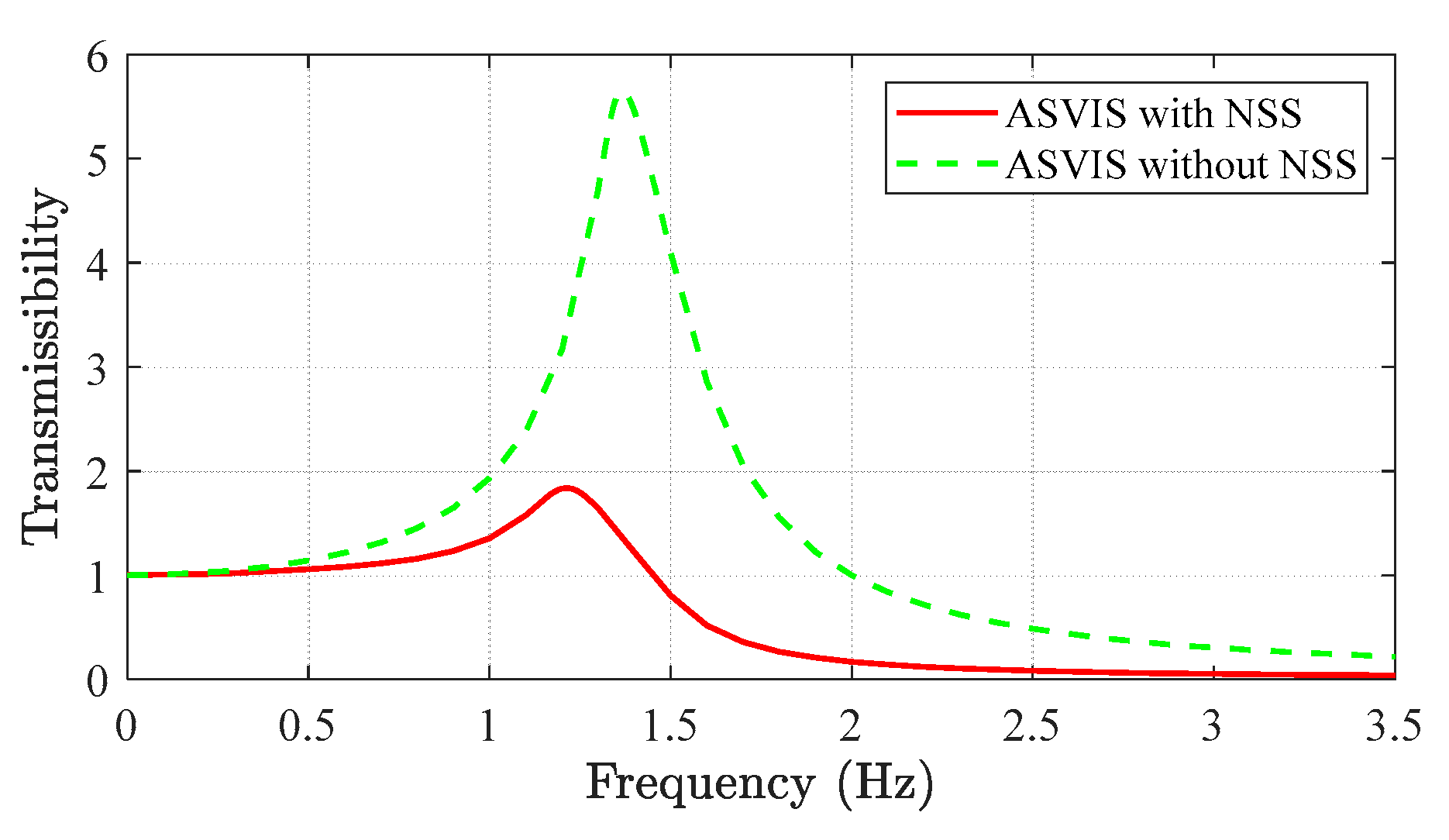
4. Simulation Results of the Air-Spring Vibration Isolator System

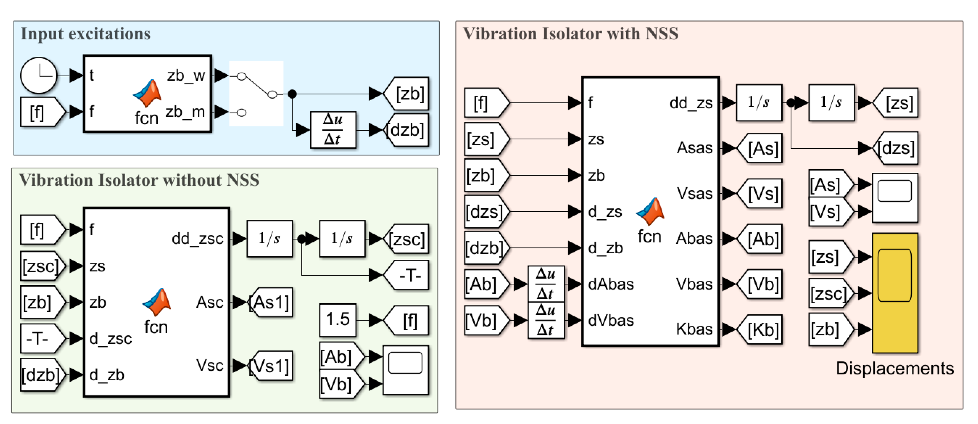
4.1. Numerical Simulation

The non-dimensional restoring force curves and the non-dimensional restoring stiffness curves are depicted in Figure 4 based on Equations (21) and (23) to demonstrate the effects of the angle α on the proposed system’s parameters. Figure 4a shows the simulation results of F ^ n s s and z ^ for different values of α . Although it is demonstrated that changing the angle α causes the stiffness curves to shift horizontally, their shape is not changed. In Figure 4b, the stiffness of the NSS in the small displacement range increases with the increase in displacement. As a result, the non-dimensional reaction forces generated by NSS are equal to zero and change direction nearby the equilibrium position. In addition, the negative stiffness of the system is symmetrical and reaches the minimum at this position. Furthermore, as the displacement value z ^ moves away from the equilibrium position, both the force and the stiffness increase. Hence, the zero stiffness can be achieved at the equilibrium position while the angle α is chosen appropriately.
From the non-dimensional stiffness curves for the different L ^ h and b ^ in Figure 5, we discovered that the NSS was realized under various stiffness characteristics. As the value L ^ h and the displacement response z ^ changed, the non-dimensional restoring stiffness moved around the static equilibrium position. Thus, if the values of L ^ h and b ^ are chosen correctly, they can provide negative stiffness over the entire displacement range.
We obtained the non-dimensional restoring forces and the non-dimensional restoring stiffness of the ASVIS with NSS, as shown in Figure 6, with dimensionless parameters such as K b s = 1 , b ^ = 1 , and L ^ h = 2 . Figure 6a presents the non-dimensional restoring forces of the proposed isolator when the angle α changed. As can be seen from Figure 6b, the minimum stiffness of the proposed system was equal to zero at the equilibrium position for α = 45 o . Moreover, the non-dimensional stiffness increased when enhancing the deviation from the equilibrium position. Hence, the dynamic stiffness of the isolator always increased, except at one position where it was zero. This means we should reasonably choose a value α to provide high isolation efficiency in the actual conditions.

4.2. Simulation Results

In order to confirm the vibration isolation ability of the proposed isolator, we compared it with the classical vibration isolator without NSS. Based on Newton’s second law, the motion equation of the ASVIS with NSS
m s z ¨ s + F s + 2 F n s s = 0
where F n s s and F s are the response forces of the negative-stiffness structure in Equation (22) and of the sleeve-type air spring in Equation (26), respectively.
The air springs used in the ASVIS with NSS were a reversible sleeve model (W02-358-7010) and a double-bellows actuator (EB-80). The values of the parameters for each type of air spring are presented in Table 1. In addition, the operating height of the sleeve-type air spring and of the bellows-type air spring were calculated for their relative displacement and height at the equilibrium position, according to Equation (31)
L h = L s e + ( z s z b ) h b = h b e + Δ L b
where L h e and h b e are the height of the sleeve-type air spring and of the bellows-type air spring at the equilibrium position, respectively.
The effective area and volume of the sleeve-type air-spring are also described by a quadratic polynomial as follows [35]:
A s ( L h ) = 5.9027 L h 3 + 3.4464 L h 2 0.6498 L h + 0.0445 V s ( L h ) = 0.0041 L h 2 + 0.007 L h 0.000213
Similarly, the effective area and volume of the air bellows were obtained according to
A b ( h b ) = 5.3157 h b 3 + 1.714 h b 2 0.2254 h b + 0.024 V b ( h b ) = 0.018 h b 2 + 0.0168 h b 0.000357

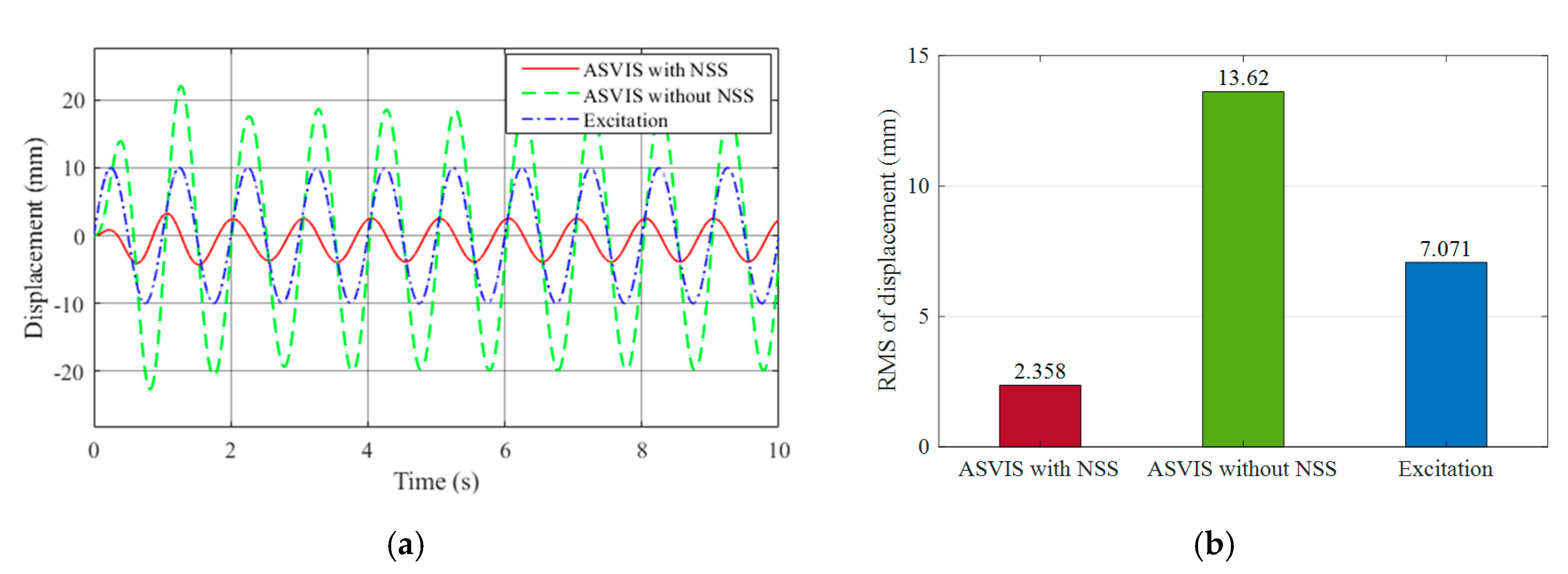
4.2.1. ASVIS under Sinusoidal Excitation

In this paper, the mathematical models and simulations were constructed by using MATLAB with Simulink 2020b. In addition, all simulation programs were created by choosing an automatic solver configuration and a sampling time of 0.01 s. The schematic block of the simulation model for the ASVIS is displayed in Figure 7.
The vibration isolation performance of the ASVIS with NSS was analyzed in the presence of sinusoidal excitation. The input excitation was a sinusoid with an amplitude of 20 mm, and the excitation frequency was 1 Hz and 3 Hz. The dimension parameters of the ASVIS in this simulation are presented in Table 2.
The displacement responses of the ASVIS with NSS and of the classical air-spring isolator without NSS for sinusoidal wave excitation were compared, as shown in Figure 8. The solid line, the dashed line, and the dotted line correspond to the ASVIS with NSS, the classical isolator without NSS, and the base excitation, respectively. The simulation results illustrated in Figure 8a showed that the ASVIS with NSS had a higher vibration attenuation rate than the traditional isolator without NSS. The root-mean-square (RMS) value of the displacement is shown in Figure 8b. When only a classical isolator was used, the RMS value of the displacement response decreased by up to 68.15%. After the ASVIS with NSS was applied, the RMS value of the displacement response was significantly reduced by 89.59%.
Similarly, the excitation frequency of 1 Hz is applied to the ASVIS with NSS and ASVIS without NSS, as shown in Figure 9. The results suggested that the displacement of the isolated object using the ASVIS with NSS significantly decreased compared with that at base excitation, whereas the vibration level of the classical isolator without NSS was higher than that at base excitation. Then, the RMS values of the ASVIS with NSS and of the classical isolator without NSS were compared, as shown in Figure 9b. This figure demonstrates that the RMS values were reduced by 66.65% when using the ASVIS with NSS, whereas, when the same excitation condition was adopted, the RMS values of the displacement response for the classical isolator without NSS increased by 92.62%.

4.2.2. ASVIS under Multi-Frequency Wave Excitation

The multi-frequency wave suggested in [11] was employed as the input displacement excitation to evaluate the vibration isolation performance of the ASVIS according to
z b = 5 sin ( 1.12 π t ) + 3.5 sin ( 3.2 π t ) + 2 cos ( 1.8 π t ) + 4 cos ( 3.6 π t )
Figure 10 displays the displacement responses of the ASVIS with NSS and ASVIS without NSS under multi-frequency excitation. The displacement response curves in function of the time of the ASVIS with NSS and of the classical isolator without NSS were compared, as shown in Figure 10a. This result illustrates that the ASVIS with NSS performed well in isolating a multi-frequency wave excitation, and the general vibration of the proposed system was remarkably reduced. As can be seen from Figure 10b, the RMS value of the displacement response of the proposed system was significantly lower than the corresponding RMS values of the classical isolator without NSS and of the base excitation. On the contrary, the vibration isolator without NSS decreased the vibration displacement in a high-frequency band, and the vibration peak value after isolation was higher than the amplitude value of the base excitation.
The vibration transmissibility of the ASVIS with NSS and of the ASVIS without NSS are compared in Figure 11. The proposed model showed a smaller resonance frequency than the ASVIS without the NSS; this was approximately 1.2 Hz for the ASVIS with NSS and 1.4 Hz for the ASVIS without NSS. As a result, the isolation region of the ASVIS with NSS expanded toward low frequencies in comparison that of with the system without NSS. In addition, the ASVIS with NSS showed lower vibration transmissibility than the ASVIS without NSS at the resonance frequency. This result proved that the vibration attenuation of the proposed model was greater than that of the ASVIS without NSS.
From the above, we can conclude that the classical air-spring isolator without NSS only decreased the vibration displacement at high excitation frequency, while the ASVIS with NSS demonstrated excellent isolation performance at lower excitation frequencies. In particular:
  • When the input frequency was lower than the natural frequency of the proposed system, the ASVIS with NSS reduced the excitation amplitude at each frequency component by more than 77.16%. On the contrary, the ASVIS without NSS increased the excitation amplitude to 102.41%.
  • When the input frequency was higher than the natural frequency of the proposed system, the displacement response of the classical isolator without the NSS decreased by up to 68.15%, while the displacement of the ASVIS with NSS remarkably was reduces by 89.59%.

5. Conclusions

This paper introduces the ASVIS with a negative-stiffness structure, which was designed to improve the driver’s safety and health under low excitation frequencies. An ASVIS includes two air bellows elements in the horizontal direction and a sleeve-type air spring element in the vertical direction. The proposed system was demonstrated to produce increased static stiffness and reduced dynamic stiffness, thus maximizing the comfort of the driver. In addition, the performance of this ASVIS was compared with that of a classical air-spring isolator via simulations with different excitations such as sinusoidal waves and multi-frequency waves. Based on the obtained results, we can conclude that the proposed ASVIS with NSS provides excellent vibration isolation performance in comparison with the classical isolator without NSS. Furthermore, the air spring structure has the advantage of reducing calculation difficulty when ASVIS is used in complex vibration isolation structures. Finally, future research may concentrate on the adaptive control of the air spring pressure in order to achieve zero dynamic stiffness over a larger range of displacements.

Author Contributions

K.K.A. was the supervisor providing funding and administrating the project; he reviewed and edited the manuscript. C.H.N. carried out the investigation, analysis and validatio, and wrote the original draft. C.M.H. checked the introduction and structure of the paper. All authors have read and agreed to the published version of the manuscript.

Funding

This research was supported by Basic Science Program through the National Research Foundation of Korea (NRF) funded by the Ministry of Science and ICT, South Korea (NRF 2020R1A2B5B03001480) and this work was supported by “Regional Innovation Strategy (RIS)” through the National Research Foundation of Korea(NRF) funded by the Ministry of Education(MOE)(2021RIS-003).

Institutional Review Board Statement

Not applicable.

Informed Consent Statement

Not applicable.

Data Availability Statement

No new data were created or analyzed in this study. Data sharing is not applicable to this article.

Conflicts of Interest

The author declares no conflict of interest.

References

  1. Griffin, M.J. Preface. In Handbook of Human Vibration; Griffin, M.J., Ed.; Academic Press: London, UK, 1990; pp. v–vii. [Google Scholar]
  2. Mansfield, N.J. Human Response to Vibration; CRC Press: Boca Raton, FL, USA, 2005. [Google Scholar] [CrossRef]
  3. Paddan, G.S.; Griffin, M.J. Evaluation of Whole-Body Vibration in Vehicles. J. Sound Vib. 2002, 253, 195–213. [Google Scholar] [CrossRef]
  4. Meng, X.; Tao, X.; Wang, W.; Zhang, C.; Cheng, B.; Wang, B.; Zhou, C.; Jin, X.; Zeng, C.; Cavanaugh, J.; et al. Effects of Sinusoidal Whole Body Vibration Frequency on Drivers’ Muscle Responses. SAE Tech. Pap. 2015, 1, 1396. [Google Scholar]
  5. Rivin, E.I. Passive Vibration Isolation; ASME Press: New York, NY, USA, 2003. [Google Scholar]
  6. Yang, J. Force transmissibility and vibration power flow behaviour of inerter-based vibration isolators. J. Phys. Conf. Ser. 2016, 744, 012234. [Google Scholar] [CrossRef] [Green Version]
  7. Yang, J.; Jiang, J.Z.; Zhu, X.; Chen, H. Performance of a dual-stage inerter-based vibration isolator. Procedia Eng. 2017, 199, 1822–1827. [Google Scholar] [CrossRef]
  8. Karnovsky, I.A.; Lebed, E. Theory of Vibration Protection; Springer: Berlin/Heidelberg, Germany, 2016. [Google Scholar]
  9. Alabuzhev, P.M.; Rivin, E.I. Vibration Protection and Measuring Systems with Quasi-Zero Stiffness; Taylor & Francis: Abingdon, UK, 1989. [Google Scholar]
  10. Platus, D. Negative-Stiffness-Mechanism Vibration Isolation Systems; SPIE Technical: OPTCON ‘91; SPIE: San Jose, CA, USA, 1992. [Google Scholar]
  11. Le, T.D.; Ahn, K.K. A vibration isolation system in low-frequency excitation region using negative stiffness structure for a vehicle seat. J. Sound Vib. 2011, 330, 6311–6335. [Google Scholar] [CrossRef]
  12. Danh, L.T.; Ahn, K.K. Active pneumatic vibration isolation system using negative stiffness structures for a vehicle seat. J. Sound Vib. 2014, 333, 1245–1268. [Google Scholar] [CrossRef]
  13. Yang, J.; Xiong, Y.P.; Xing, J.T. Dynamics and power flow behaviour of a nonlinear vibration isolation system with a negative stiffness mechanism. J. Sound Vib. 2013, 332, 167–183. [Google Scholar] [CrossRef]
  14. Shi, B.; Yang, J.; Li, T. Enhancing Vibration Isolation Performance by Exploiting Novel Spring-Bar Mechanism. Appl. Sci. 2021, 11, 8852. [Google Scholar] [CrossRef]
  15. Sun, M.; Dong, Z.; Song, G.; Sun, X.; Liu, W. A Vibration Isolation System Using the Negative Stiffness Corrector Formed by Cam-Roller Mechanisms with Quadratic Polynomial Trajectory. Appl. Sci. 2020, 10, 3573. [Google Scholar] [CrossRef]
  16. Yao, Y.; Li, H.; Li, Y.; Wang, X. Analytical and experimental investigation of a high-static-low-dynamic stiffness isolator with cam-roller-spring mechanism. Int. J. Mech. Sci. 2020, 186, 105888. [Google Scholar] [CrossRef]
  17. Zheng, Y.; Zhang, X.; Luo, Y.; Yan, B.; Ma, C. Design and experiment of a high-static–low-dynamic stiffness isolator using a negative stiffness magnetic spring. J. Sound Vib. 2016, 360, 31–52. [Google Scholar] [CrossRef]
  18. Palomares, E.; Nieto, A.J.; Morales, A.L.; Chicharro, J.M.; Pintado, P. Numerical and experimental analysis of a vibration isolator equipped with a negative stiffness system. J. Sound Vib. 2018, 414, 31–42. [Google Scholar] [CrossRef]
  19. Carrella, A.; Brennan, M.J.; Waters, T.P. Static analysis of a passive vibration isolator with quasi-zero-stiffness characteristic. J. Sound Vib. 2007, 301, 678–689. [Google Scholar] [CrossRef]
  20. Lan, C.-C.; Yang, S.-A.; Wu, Y.-S. Design and experiment of a compact quasi-zero-stiffness isolator capable of a wide range of loads. J. Sound Vib. 2014, 333, 4843–4858. [Google Scholar] [CrossRef]
  21. Chang, Y.; Zhou, J.; Wang, K.; Xu, D. A quasi-zero-stiffness dynamic vibration absorber. J. Sound Vib. 2021, 494, 115859. [Google Scholar] [CrossRef]
  22. Liu, C.; Yu, K. Accurate modeling and analysis of a typical nonlinear vibration isolator with quasi-zero stiffness. Nonlinear Dyn. 2020, 100, 2141–2165. [Google Scholar] [CrossRef]
  23. Yang, J.; Jiang, J.Z.; Neild, S.A. Dynamic analysis and performance evaluation of nonlinear inerter-based vibration isolators. Nonlinear Dyn. 2019, 99, 1823–1839. [Google Scholar] [CrossRef] [Green Version]
  24. Zhou, J.; Wang, X.; Xu, D.; Bishop, S. Nonlinear dynamic characteristics of a quasi-zero stiffness vibration isolator with cam–roller–spring mechanisms. J. Sound Vib. 2015, 346, 53–69. [Google Scholar] [CrossRef]
  25. Ye, K.; Ji, J.C.; Brown, T. Design of a quasi-zero stiffness isolation system for supporting different loads. J. Sound Vib. 2020, 471, 115198. [Google Scholar] [CrossRef]
  26. Yuan, S.; Sun, Y.; Zhao, J.; Meng, K.; Wang, M.; Pu, H.; Peng, Y.; Luo, J.; Xie, S. A tunable quasi-zero stiffness isolator based on a linear electromagnetic spring. J. Sound Vib. 2020, 482, 115449. [Google Scholar] [CrossRef]
  27. Sun, X.; Jing, X.; Xu, J.; Cheng, L. Vibration isolation via a scissor-like structured platform. J. Sound Vib. 2014, 333, 2404–2420. [Google Scholar] [CrossRef]
  28. Sun, M.; Song, G.; Li, Y.; Huang, Z. Effect of negative stiffness mechanism in a vibration isolator with asymmetric and high-static-low-dynamic stiffness. Mech. Syst. Signal Process. 2019, 124, 388–407. [Google Scholar] [CrossRef]
  29. Wei, C.; Zhang, K.; Hu, C.; Wang, Y.; Taghavifar, H.; Jing, X. A tunable nonlinear vibrational energy harvesting system with scissor-like structure. Mech. Syst. Signal Process. 2019, 125, 202–214. [Google Scholar] [CrossRef]
  30. Quaglia, G.; Sorli, M. Air Suspension Dimensionless Analysis and Design Procedure. Veh. Syst. Dyn. 2001, 35, 443–475. [Google Scholar] [CrossRef]
  31. Lee, C.M.; Goverdovskiy, V.N.; Temnikov, A.I. Design of springs with “negative” stiffness to improve vehicle driver vibration isolation. J. Sound Vib. 2007, 302, 865–874. [Google Scholar] [CrossRef]
  32. Palomares, E.; Morales, A.L.; Nieto, A.J.; Chicharro, J.M.; Pintado, P. Improvement of Comfort in Suspension Seats with a Pneumatic Negative Stiffness System. Actuators 2020, 9, 126. [Google Scholar] [CrossRef]
  33. Qi, Z.; Li, F.; Yu, D. A three-dimensional coupled dynamics model of the air spring of a high-speed electric multiple unit train. Proc. Inst. Mech. Eng. Part F J. Rail Rapid Transit 2016, 231, 3–18. [Google Scholar] [CrossRef]
  34. Chen, J.-J.; Yin, Z.-H.; Rakheja, S.; He, J.-H.; Guo, K.-H. Theoretical modeling and experimental analysis of the vertical stiffness of a convoluted air spring including the effect of the stiffness of the bellows. Proc. Inst. Mech. Eng. Part D J. Automob. Eng. 2017, 232, 547–561. [Google Scholar] [CrossRef]
  35. Beater, P. “Pneumatic Drives”, System Design, Modelling and Control; Springer Nature: Cham, Switzerland, 2007; p. XIV, 324. [Google Scholar] [CrossRef]
Figure 1. (a) Model of ASVIS with NSS, (b) schematic diagram of ASVIS at the static equilibration position. 1. Negative-stiffness structure; 2. crisscross structure; 3. sleeve air spring; 4. isolated object; 5. upper linear guide; 6. linear support; 7. upper plate; 8. bracket; 9. linear shaft; 10. linear bushings; 11. base support; 12. base; 13. bellows fork; 14. left link; 15. air bellows; 16. right link; 17. rotating joint; 18. bellows linear guide; 19. straight bar; 20. pin.
Applsci 11 11539 g001
Figure 2. Analytical model of (a) the sleeve-type air spring and (b) the bellows-type air spring. 1. Bead plate; 2. bellows; 3. piston; 4. orifice; 5. auxiliary tank.
Applsci 11 11539 g002
Figure 3. Schematic diagram of the negative-stiffness structure and the crisscross structure.
Applsci 11 11539 g003
Figure 4. Non-dimensional force and non-dimensional stiffness of the NSS with L ^ h = 2 and b ^ = 1 . (a) Non-dimensional force; (b) non-dimensional stiffness.
Applsci 11 11539 g004
Figure 5. Non-dimensional stiffness of the NSS for different L ^ h and b ^ with α = 45 o . (a) Non-dimensional stiffness of the ASVIS for different L ^ h ; (b) non-dimensional stiffness of the NSS for different L ^ h .
Applsci 11 11539 g005
Figure 6. Non-dimensional force and non-dimensional stiffness of the ASVIS with NSS. (a) Non-dimensional force; (b) non-dimensional stiffness.
Applsci 11 11539 g006
Figure 7. Structure of the simulation model for the proposed isolators.
Applsci 11 11539 g007
Figure 8. Comparison between the ASVIS isolator with NSS and the classical isolator without NSS for input frequency 3 Hz. (a) Displacement response; (b) RMS value of the displacement.
Applsci 11 11539 g008
Figure 9. Comparison between the ASVIS with NSS and the classical isolator without NSS for input frequency 1 Hz. (a) Displacement response; (b) RMS value of the displacement.
Applsci 11 11539 g009
Figure 10. Displacement responses under multi-frequency wave excitation. (a) Displacement responses; (b) RMS value of the displacement.
Applsci 11 11539 g010
Figure 11. Frequency response curves for the ASVIS.
Applsci 11 11539 g011
Table 1. Parameter of the sleeve-type air spring and bellows-type air spring.
ParameterValveUnit
n1.4
T293K
P a 1.103 × 10⁵Pa
P s e 3.77 × 10⁵Pa
P b e 3.50 × 10⁵Pa
L s e 200mm
h b e 80mm
Table 2. Dimension parameters of the proposed system in the simulation.
ParameterValveUnit
m150kg
a200mm
b200mm
L b 200mm
L h 282.84mm
Publisher’s Note: MDPI stays neutral with regard to jurisdictional claims in published maps and institutional affiliations.

