Article

Simplified 2D Finite Element Model for Calculation of the Bearing Capacity of Eccentrically Compressed Concrete-Filled Steel Tubular Columns

by
Anton Chepurnenko
1,*,
Batyr Yazyev
1,
Besarion Meskhi
2,
Alexey Beskopylny
3,*,
Kazbek Khashkhozhev
1 and
Viacheslav Chepurnenko
1
1
Strength of Materials Department, Faculty of Civil and Industrial Engineering, Don State Technical University, 344003 Rostov-on-Don, Russia
2
Department of Life Safety and Environmental Protection, Faculty of Life Safety and Environmental Engineering, Don State Technical University, Gagarin, 1, 344003 Rostov-on-Don, Russia
3
Department of Transport Systems, Faculty of Roads and Transport Systems, Don State Technical University, Gagarin, 1, 344003 Rostov-on-Don, Russia
*
Authors to whom correspondence should be addressed.
Appl. Sci. 2021, 11(24), 11645; https://doi.org/10.3390/app112411645
Submission received: 18 November 2021 / Revised: 3 December 2021 / Accepted: 6 December 2021 / Published: 8 December 2021
(This article belongs to the Special Issue Reinforced Concrete: Materials, Physical Properties and Applications)

Abstract

:
Concrete-filled steel tubular (CFST) columns are widely used in construction due to effective resistance to compression and bending joint action. However, currently, there is no generally accepted effective calculation method considering both nonlinearities of the materials and lateral compression. The article proposes the finite element analysis method of concrete-filled steel tubular columns in a physically nonlinear formulation by reducing a three-dimensional problem to a two-dimensional one based on the hypothesis of plane sections. The equations of Geniev’s concrete theory of plasticity are used as relations establishing the relationship between stresses and strains. The technique was tested by comparing the solution with the calculation in a three-dimensional formulation in the LIRA-SAPR software package and with the experimental data of A.L. Krishan and A.I. Sagadatov. It has been established that the effective area of operation of circular-section columns are small eccentricities of the longitudinal force. The proposed approach can be applied to analyzing the stress–strain state and bearing capacity of pipe-concrete columns of arbitrary cross-sections. There are no restrictions on the composition of concrete, and the shell material can be steel and fiberglass.

1. Introduction

Concrete-filled tubular steel tubular columns (CFST) are now increasingly used in construction, especially in the construction of high-rise buildings [1,2,3,4], due to several significant advantages, including high load-bearing capacity, quick construction, as well as lower materials consumption and production expenses. However, one of the considerable disadvantages of CFST columns is the lack of generally accepted design methods that consider the effect of lateral deformation of concrete.
There is no universal method suitable for an arbitrary cross-section of a tubular column, which, in addition to round, can be rectangular, hexagonal, and other shapes.
Experimental studies of the compression characteristics and plasticity of rectangular concrete-filled steel pipes were carried out in [5,6] under single and multiple uniaxial compression. The authors investigated hysteresis curves, frame curves, energy dissipation capacity, bearing capacity, stiffness, and deformation of specimens and the effect on axial compression characteristics based on various structural features. The experimental studies show that structural elements in the form of longitudinal stiffeners installed inside the columns contribute to the separation of axial forces and increase the structure’s rigidity, load-bearing capacity, and plasticity. In addition, installing internal diaphragms inside the columns can significantly increase the ultimate load-bearing capacity and energy dissipation.
Since high-strength materials are increasingly used in construction, an extensive experimental database has been developed in [7], for square and rectangular columns. Although the results showed that the existing regulatory framework is not effective for high-strength materials, the flexibility of square and rectangular columns can be safely reduced.
Axial compression tests were carried out in [8] on rectangular concrete-filled steel pipe columns under various loading methods. In [9], the authors experimentally investigated 17 rectangular CFST columns subjected to eccentric loading on uniaxial and biaxial bending. The influence of the limiting factor and the eccentric ratio on the strength and ductility of the samples was investigated.
The assessment of the stress–strain state of hexagonal steel columns filled with concrete was carried out in [10,11,12] by the finite element method. The columns were subjected to axial compressive forces and cyclic bending moments. Based on the FEM model, the authors determined the hysteresis characteristics of the columns, the contact stress between the steel pipe and concrete, and the contribution of the strength of various components over the entire load range. In [13], the authors note that concrete-filled tubular steel columns with rounded ends have the same advantages as regular CFST columns. 3D finite element models for columns are developed using ABAQUS software. Numerical results show that brittle fracture is associated with columns formed from outer thin steel cross-sections.
Experimental and numerical studies of the structural characteristics of cold-formed high-strength steel octagonal tubular columns filled with concrete are presented in [14]. The authors studied ultimate loads, load-displacement reactions, and structural failure modes experimentally and numerically.
The specifics of calculating the strength of short, centrally compressed concrete, steel pipe columns of the annular cross-section are considered in [15,16]. In addition, the complex stress state of the concrete core and the steel shell and the uneven distribution of transverse stresses over the cross-section of the design elements are taken into account.
Except for steel, fiberglass can be used as the shell material [17]. Unfortunately, most of the publications on the methods of calculating tube-shaped concrete, including those listed above, are based on an empirical approach that does not fully reflect the specifics of changes in the stress–strain state of columns under various loads. This imposes restrictions on the cross-sectional shape, shell material, and concrete composition (heavy and lightweight concrete, high strength concrete, regular concrete, etc.).
Experimental studies of the stress–strain state of elliptical and oval columns made of concrete tubes subjected to axial compressive load were carried out in [18,19]. Various column lengths, cross-sectional sizes, and concrete strengths are used to quantify the effect of element geometry and constituent material properties on the structural behavior of CFST elliptical columns.
Experimental and numerical studies of the steel tubular column filled with concrete with an unequal wall thickness under eccentric compression were performed in [20]. The series of compression tests were performed on rectangular CFST columns with varying flexibilities, eccentricities, and wall thicknesses. The test results show that a rectangular CFST column with unequal wall thickness has higher ductility after peak load than a column with the same wall thickness with the same configuration.
The behavior of carbon-polymer columns reinforced with vertically bent hollow steel beams was investigated in [21]. Sixteen curved beams with a span of 1200 mm, with four radii of curvature; 0 mm, 2000 mm, 4000 mm, and 6000 mm were tested for three-point bending. A theoretical model was also developed and validated to predict the elastic behavior of CFST reinforced tubular beams using the integral Maxwell–Mohr method.
A high-strength, low-magnesia (CFST) concrete-filled tubular steel column was investigated in [22] under eccentric loading. Seven groups of columns with different eccentricity factors were experimentally studied, and the ultimate load of each test was compared with the design loads from several specifications. The results of the load–vertical deflection curves show that, with the same eccentricity, the bearing capacity of the test specimens is 12% higher than that of high-strength concrete from steel pipes. The technological features of the manufacture of concrete tubular columns, their properties, and calculation methods under static and dynamic influences are considered in [23,24,25,26,27].
The above review shows that most of the work related to the study of the stress–strain state of CFST is carried out experimentally or numerically in a simplified formulation. The results that are closest to the real work of structures are provided by finite element modeling in a volumetric setting, taking into account the physical nonlinearity of the material [28]. However, this approach requires a lot of computational time.
Thus, this work aims to develop a method that considers the nonlinear properties of the CFST materials, which makes it possible to reduce the dimension of the problem of determining the stress–strain state from three-dimensional to two-dimensional without a noticeable loss of accuracy of the results.
In the framework of the set goal, the following tasks are solved:
  • Derivation of the resolving equations and computer implementation of the method for nonlinear calculation of concrete-filled steel tubular columns by reducing the three-dimensional problem to the two-dimensional one.
  • Verification of the method and the developed software by comparison with calculations in existing software complexes in the three-dimensional setting.
  • Approbation of the developed method on existing experimental data.
  • Study of the peculiarities of the stress–strain state of columns at various eccentricities of the longitudinal force.

2. Materials and Methods

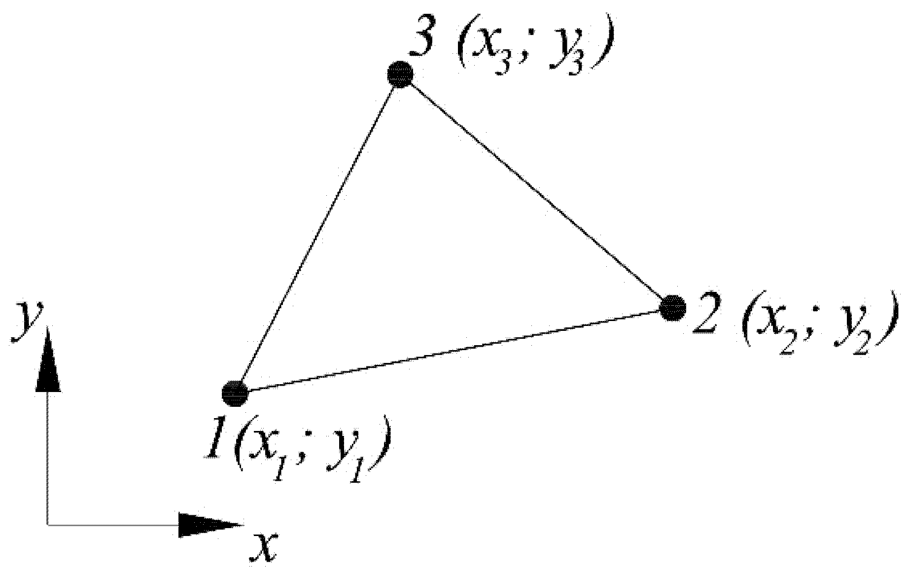
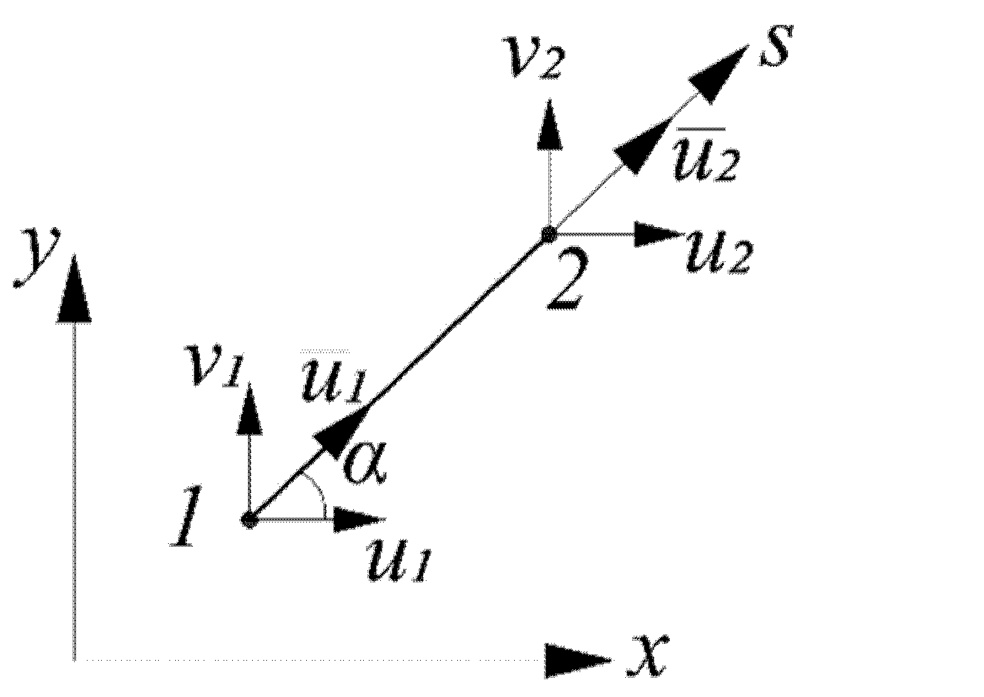
The calculation scheme of the structure is shown in Figure 1. The three-dimensional problem can be reduced to the two-dimensional one by introducing the hypothesis of plane sections. Plane triangular finite elements (FE) for concrete (Figure 2) and one-dimensional two-node finite elements for the steel shell (Figure 3) will be used.
Plane triangular finite elements have 2 degrees of freedom at each node (displacements ui and vi). Linear functions perform displacement approximation
u = N 1 u 1 + N 2 u 2 + N 3 u 3 v = N 1 v 1 + N 2 v 2 + N 3 v 3
where N i = 1 2 A ( a i + b i x + c i y ) , A is the area of the finite element, a 1 = x 2 y 3 x 3 y 2 , b 1 = y 2 y 3 ,   c 1 = x 3 x 2 .
Coefficients a2, b2, c2, a3, b3, c3 are determined by cyclically changing the indices 1 → 2 → 3 → 1.
The strain vector in the xy plane is written as
{ ε } = { ε x ε y γ x y } = { u x v y u y + v x } = [ B ] { U } ,
where [ B ] = 1 2 A [ b 1 0 b 2 0 b 3 0 0 c 1 0 c 2 0 c 3 c 1 b 1 c 2 b 2 c 3 b 3 ] ,   { U } = { u 1 v 1 u 2 v 2 u 3 v 3 } T is the vector of nodal displacements.
The deformation εz is represented as a sum of the axial deformation ε z 0 and the deformation caused by the change in curvature χ
ε z = ε z 0 + y χ .
When deriving the resolving equations, the presence of forced deformations ε x * ,   ε y * ,   ε z * ,   γ x y —which may include creep deformations, shrinkage, temperature deformations, dilatation effects, etc.—is considered. The relationship between stresses and deformations of concrete, taking into account forced deformations, is written in the form
ε x = 1 E ( σ x ν ( σ y + σ z ) ) + ε x * ; ε y = 1 E ( σ y ν ( σ x + σ z ) ) + ε y * ; ε z = 1 E ( σ z ν ( σ y + σ x ) ) + ε z * ; γ x y = 2 ( 1 + ν ) E τ x y + γ x y * .
From (4) the stress σz can be excluded
σ z = E ( ε z ε z * ) + ν ( σ y + σ x ) = E ( ε z 0 + y χ ε z * ) + ν ( σ y + σ x ) .
Substituting (5) into the first two equations in Equation (4), following equations can be obtained
ε x = 1 E 1 ( σ x ν 1 σ y ) + ε x * ν ( ε z 0 + y χ ε z * ) ; ε y = 1 E 1 ( σ y ν 1 σ x ) + ε y * ν ( ε z 0 + y χ ε z * ) ,
where E 1 = E / ( 1 ν 2 ) ,   ν 1 = ν / ( 1 ν ) .
The last equation in (4) can be written as
γ x y = 2 ( 1 + ν 1 ) E 1 τ x y + γ x y * .
Let us express in (6) and (7) stresses through deformations
σ x = E 1 1 ν 1 2 ( ε x + ν 1 ε y ( ε x * + ν 1 ε y * ) + ν ( 1 + ν 1 ) ( ε z 0 + y χ ε z * ) ) = = E 1 1 ν 1 2 ( ε x + ν 1 ε y ( ε x * + ν 1 ε y * ) + ν 1 ( ε z 0 + y χ ε z * ) ) ; σ y = E 1 1 ν 1 2 ( ε y + ν 1 ε x ( ε y * + ν 1 ε x * ) + ν 1 ( ε z 0 + y χ ε z * ) ) ; τ x y = E 1 2 ( 1 + ν 1 ) ( γ x y γ x y * ) .
Let us write Equality (8) in matrix form
{ σ } = [ D ] ( { ε } { ε * } ) + { σ 1 } ,
where [ D ] = E 1 1 ν 1 2 [ 1 ν 1 0 ν 1 1 0 0 0 1 ν 1 2 ] ,   { σ } = { σ x σ y τ x y } ,   { ε } = { ε x ε y γ x y } , { ε } = { ε x * ε y * γ x y * } , { σ 1 } = E 1 ν 1 1 ν 1 2 ( ε z 0 + y χ ε z * ) { 1 1 0 } .
Equality (5) can be represented in the form
σ z = E ( ε z 0 + y χ ε z * ) + ν ( σ y + σ x ) = E ( ε z 0 + y χ ε z * ) + ν { σ } T { 1 1 0 } .
When deriving the resolving equations, the principle of the minimum total energy was used. The potential energy of deformation of the concrete-filled steel tubular element is the sum of the potential energy of concrete b and steel s . The value of b is determined by the formula
b = 1 2 A ( σ x ε x e l + σ y ε y e l + τ x y γ x y e l + σ z ε z e l ) d A .
The subscripts “el” in Formula (11) correspond to elastic deformations, which represent the difference between total and forced deformations. Expression (11) can be represented in the form
b = 1 2 A σ z ( ε z 0 + y χ ε z * ) d A + 1 2 A { σ } T ( { ε } { ε * } ) d A .
Let us consider the first integral separately in (12)
1 2 A σ z ( ε z 0 + y χ ε z * ) d A = 1 2 A E ( ε z 0 + y χ ε z * ) 2 d A + ν 2 A { σ } T { 1 1 0 } ( ε z 0 + y χ ε z * ) d A .
The first term in (13) vanishes after minimization over the nodal displacement vector {U}. The second term can be represented in the form
ν 2 A { σ } T { 1 1 0 } ( ε z 0 + y χ ε z * ) d A = ν 2 A ( { σ 1 } T + ( { ε } T { ε * } T ) [ D ] ) { 1 1 0 } ( ε z 0 + y χ ε z * ) d A = = ν 2 ( A ( { σ 1 } T { ε * } T [ D ] ) { 1 1 0 } ( ε z 0 + y χ ε z * ) d A + A { U } T [ B ] T [ D ] { 1 1 0 } ( ε z 0 + y χ ε z * ) d A ) .
The first integral in (14) also vanishes after minimization. In the second integral, it can be assumed that the deformation ε z within the finite element is constant. With this in mind, it is presented in the form
ν 2 A { U } T [ B ] T [ D ] { 1 1 0 } ( ε z 0 + y χ ε z * ) d A = ν 2 { U } T [ B ] T [ D ] { 1 1 0 } ( ( ε z 0 ε z * ) A + χ A y d A ) = = 1 2 { U } T [ B ] T A · ν [ D ] { 1 1 0 } ( ε z 0 + y c χ ε z * ) = 1 2 { U } T [ B ] T A E 1 ν 1 1 ν 1 2 { 1 1 0 } ( ε z 0 + y c χ ε z * ) = = 1 2 { U } T [ B ] T A { σ 1 } .
In Formula (15) yc = (y1 + y2 + y3)/3 is the coordinate of the center of gravity of the finite element.
Let us further consider the second term in (12)
1 2 A { σ } T { ε e l } d A = 1 2 A [ ( { ε } T { ε * } T ) [ D ] + { σ 1 } T ] ( { ε } { ε * } ) d A = = 1 2 A { ε } T [ D ] { ε } 2 { ε } T [ D ] { ε * } + { ε * } T [ D ] { ε * } + { σ 1 } T { ε } { σ 1 } T { ε * } d A .
The terms { ε * } T [ D ] { ε * } and { σ 1 } T { ε * } after minimization with respect to {U} vanish. Let us consider each of the remaining terms separately
1 2 A { ε } T [ D ] { ε } d A = 1 2 { U } T [ B ] T [ D ] [ B ] A { U } = 1 2 { U } T [ K b ] { U } ,
where [ K b ] = [ B ] T [ D ] [ B ] A is the concrete stiffness matrix.
1 2 A { σ 1 } T { ε } d A = 1 2 A { ε } T { σ 1 } d A = 1 2 { U } T [ B ] T { σ 1 } A ; A { ε } T [ D ] { ε * } d A = { U } T [ B ] T [ D ] { ε * } A = { U } T { F * } .
For the FE of steel shell, the displacements are approximated as
u ( s ) = u 1 + u 2 u 1 l s .
The circumferential deformations of the shell are defined as
ε s θ = d u d s = [ 1 l 1 l ] { u 1 u 2 } = [ B s ] { U s } .
These formulas calculate the stresses in the steel
σ s θ = E s 1 ν s 2 ( ε s θ + ν s ε s z ) = E s 1 ν s 2 ( ε s θ + ν s ( ε z 0 + y s χ ) ) ; σ s z = E s 1 ν s 2 ( ε s z + ν s ε s θ ) = E s 1 ν s 2 ( ε z 0 + y s χ + ν s ε s θ ) .
The ys coordinate within the FE is not constant. For convenience, it can be calculated in the middle of the element. The potential deformation energy of the FE is written in the form
s = 1 2 ( δ 0 l σ s θ ε s θ d s + δ 0 l σ s z ε s z d s ) .
The first integral in (22) is defined as
δ 0 l σ s θ ε s θ d s = E s δ 1 ν s 2 0 l ( { U s } T [ B s ] T + ν s ( ε z 0 + y s χ ) ) [ B s ] { U s } d s = = E s δ l 1 ν s 2 { U s } T [ B s ] T [ B s ] { U s } + E s ν s δ l 1 ν s 2 ( ε z 0 + y s χ ) [ B s ] { U s } = = { U s } T [ K s ] { U s } + { U s } T [ B s ] T E s ν s δ l 1 ν s 2 ( ε z 0 + y s χ ) ,
where [ K s ] = E s δ l 1 ν s 2 [ B s ] T [ B s ] = E s δ l ( 1 ν s 2 ) [ 1 1 1 1 ] —stiffness matrix of the steel cage.
The second integral in (22) is calculated as
δ 0 l σ s z ε s z d s = E s δ 1 ν s 2 0 l ( ε z 0 + y s χ + ν s { U s } T [ B s ] T ) ( ε z 0 + y s χ ) d s = = E s δ 1 ν s 2 ( 0 l ( ε z 0 + y s χ ) 2 d s + ν s 0 l ( ε 0 + y s χ ) [ B s ] { U s } d s ) .
The first integral in (24) vanishes after minimization over the vector of nodal displacements. The second integral is written as
E s δ ν s 1 ν s 2 0 l ( ε 0 + y s χ ) [ B s ] { U s } d s = { U s } T [ B s ] T E s δ ν s l 1 ν s 2 ( ε z 0 + y s χ ) .
External forces on the displacements of the CFST column in the xy plane do not perform work; therefore, the total energy functional for the problem under consideration is equal to the potential deformation energy. By minimizing the potential energy of deformation along the vector of nodal displacements, a system of linear algebraic equations can be obtained
[ K ] { U } + { F b } + { F s } { F * } = 0 ,
where [ K ] = [ K b ] + [ K s ] , { F b } = [ B ] T { σ 1 } A = [ B ] T A E 1 ν 1 1 ν 1 2 ( ε z 0 + y c χ ε z * ) { 1 1 0 } ,  
{ F s } = [ B s ] T E s δ ν s l 1 ν s 2 ( ε z 0 + y s χ ) .
The vector {Fs} in (27), as well as the matrix [Ks] in (23) are written in the local coordinate system of the element. When compiling the system of equations of the FEM, the coordinates are transformed according to the formulas
{ U ¯ } = [ L ] { U } ;   [ K ] = [ L ] T [ K ¯ ] [ L ] ;   { F } = [ L ] T { F ¯ } ;   [ L ] = [ cos α sin α 0 0 0 0 cos α sin α ] .
where { U ¯ } , { F ¯ } , [ K ¯ ] are the nodal displacement vector, load vector, and stiffness matrix in the local coordinate system; { U } , { F } , [ K ] are the same for the global coordinate system.
System (26), in addition to the vector of nodal displacements, contains two more unknowns: the quantities ε z 0 and χ. Equilibrium conditions act as two additional equations
F = σ z , i A i δ σ s z , i l i ; M = F e = σ z , i y c , i A i δ σ s z , i y s , i l i .
The stress σz in the i-th triangular FE of concrete is defined as
σ z = E ( ε z 0 + y c χ ε z * ) + ν ( σ x + σ y ) = E ( ε z 0 + y c χ ε z * ) + ν { 1 1 0 } { σ } = = E ( ε z 0 + y c χ ε z * ) + ν { 1 1 0 } ( [ D ] ( [ B ] { U } { ε * } ) + { σ 1 } ) = = ( E + 2 E 1 ν 1 1 ν 1 2 ) ( ε z 0 + y c χ ε z * ) + ν { 1 1 0 } [ D ] ( [ B ] { U } { ε * } ) .
The stress σsz in the i-th one-dimensional FE of the steel shell is defined as
σ s z = E s 1 ν s 2 ( ε z 0 + y s χ + ν s ε s θ ) = E s 1 ν s 2 ( ε z 0 + y s χ + ν s [ B s ] [ L ] { U } ) .
Thus, for the total number of nodes n, the problem is reduced to 2n + 2 equations with 2n + 2 unknowns.
As equations establishing the relationship between stresses and deformations in concrete, the dependences of the deformational theory of plasticity of concrete by G.A. Geniev [29] can be used as
ε x = 1 E ( Γ ) ( σ x ν ( σ y + σ z ) ) + ε d ; ε y = 1 E ( Γ ) ( σ y ν ( σ x + σ z ) ) + ε d ; ε z = 1 E ( Γ ) ( σ z ν ( σ x + σ y ) ) + ε d ; γ x y = 2 ( 1 + ν ) E ( Γ ) τ x y ,
where ε d = g 0 Γ 2 / 3 are the dilatation deformations, g0 is the dilatation module, Γ = 2 3 ( ε 1 ε 2 ) 2 + ( ε 2 ε 3 ) 2 + ( ε 1 ε 3 ) 2 is the intensity of shear deformations.
Dilatation deformations can be considered as a special case of forced deformations ε x * ,   ε y * ,   ε z * .
The dilatation modulus g0 in Geniev’s theory is defined as
g 0 = θ c Γ c 2 ,
where θ c is the ultimate volumetric deformation of concrete at pure shear, Γ c is the limiting intensity of shear strains at pure shear, calculated as
Γ c = 2 T c G 0 .
In Formula (33) T c = R b R b t / 3 is the limiting intensity of shear stresses, Rb and Rbt are the compressive and tensile strength of concrete, respectively, G0 = E0/(2 (1 + νb)) is the initial shear modulus of concrete, E0 is the initial modulus of elasticity of concrete.
The formula determines the secant module E(Γ)
E ( Γ ) = E 0 ( 1 Γ 2 Γ s ) ,
where Γs is the limiting intensity of shear deformations, depending on the nature of the stress state
Γ s = Γ c k ( λ , ω ) ,   k ( λ , ω ) = λ ( 1 + ω ) 2 + λ 2 ( 1 + ω ) 2 4 + ( 1 + ω ) .
The parameter ω in (35) is defined as
ω = e ( S T ) 3 ,
where T = 1 6 ( σ 1 σ 2 ) 2 + ( σ 2 σ 3 ) 2 + ( σ 1 σ 3 ) 2 is the shear stress intensity, e = R b R b t 3 T c 2 1 , S = 3 [ 1 2 ( σ 1 σ ) ( σ 2 σ ) ( σ 3 σ ) ] 1 3 ,   σ = ( σ 1 + σ 2 + σ 3 ) / 3 .
The parameter λ in (35) is calculated by the formula
λ = f σ T ,
where f = 3 T c ( R b R b t ) R b R b t .
The calculation is performed by a stepwise method. The load is increased in small portions ΔF. The dilatation strain increment is defined as
Δ ε d = ε d ( Γ + Δ Γ ) ε d ( Γ ) = g 0 3 ( Γ 2 + 2 Γ Δ Γ + Δ Γ 2 ) g 0 3 Γ 2 = = g 0 3 ( 2 Γ Δ Γ + Δ Γ 2 ) .
The value of ΔΓ2 in comparison with the first term in the parenthesis can be neglected, since it is a quantity of a higher order of smallness, and then Formula (38) takes the form
Δ ε d = 2 g 0 Γ Δ Γ 3 .
The material of the shell is assumed to be ideal elastoplastic; the Huber-Mises-Genka plasticity condition is used
1 2 σ s z 2 σ s z σ s θ + σ s θ 2 = R y ,
where Ry is the yield strength of steel.
For calculations, the authors have developed the program in the MATLAB environment.

3. Results

To control the accuracy of the equations obtained and the developed methodology, the first step was to solve the test problem in elastic formulation with subsequent comparison in the LIRA-SAPR software package [30]. The solution was carried out with the following initial data: D = 0.3 m, δ = 2 mm, Eb = 3 × 10⁴ MPa, Es = 2 × 10⁵ MPa, F = 100 kN, e = D/2, νs = 0.3, νb = 0.2. By virtue of symmetry, half of the cross-section was considered. The LIRA-SAPR software package solved the problem in the three-dimensional formulation, volumetric prismatic FE modeled concrete, and the steel shell was modeled by flat shell FE. To exclude local effects at the point of application of the force, the plate of high rigidity was installed at the upper end of the column. The calculation scheme is shown in Figure 4.
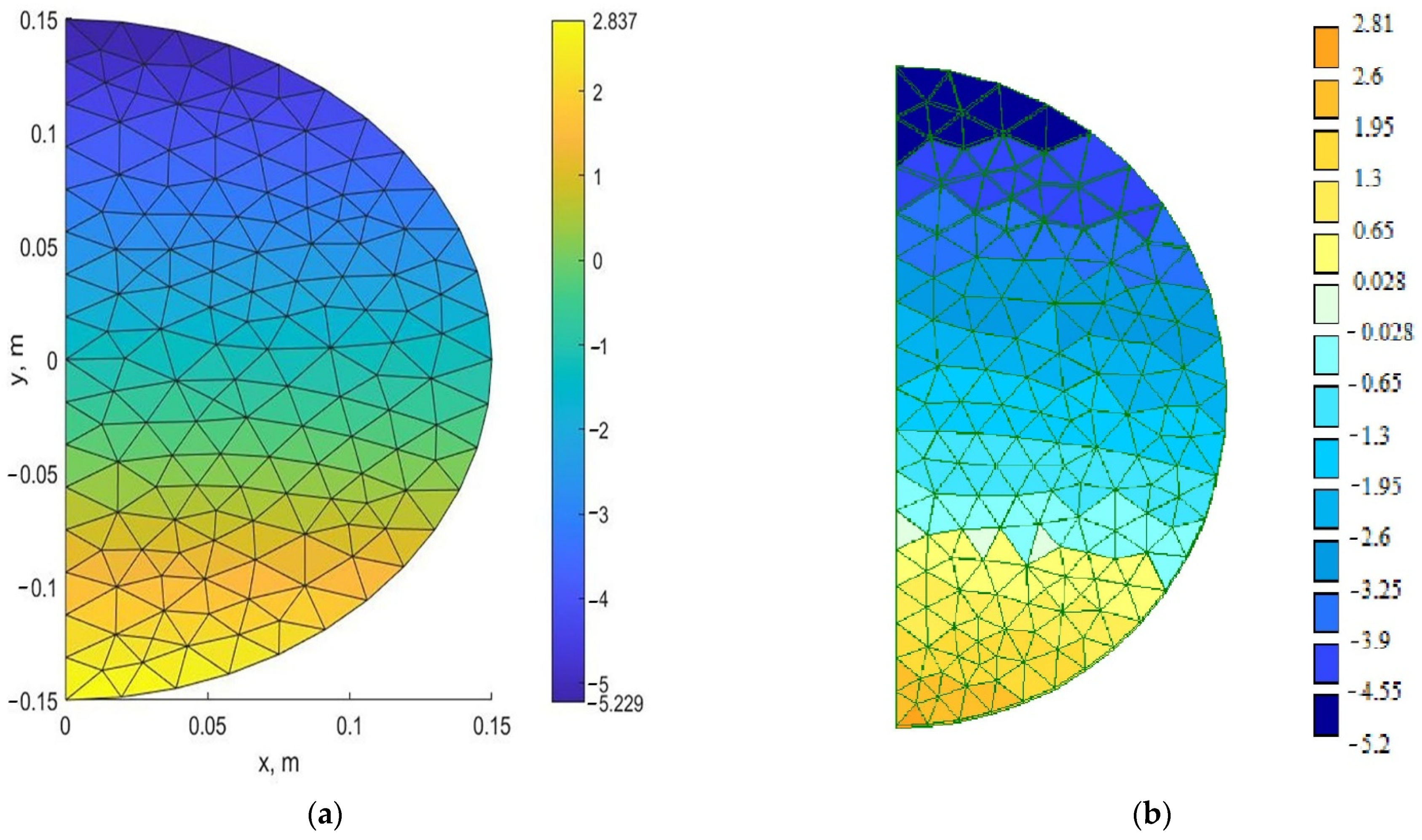
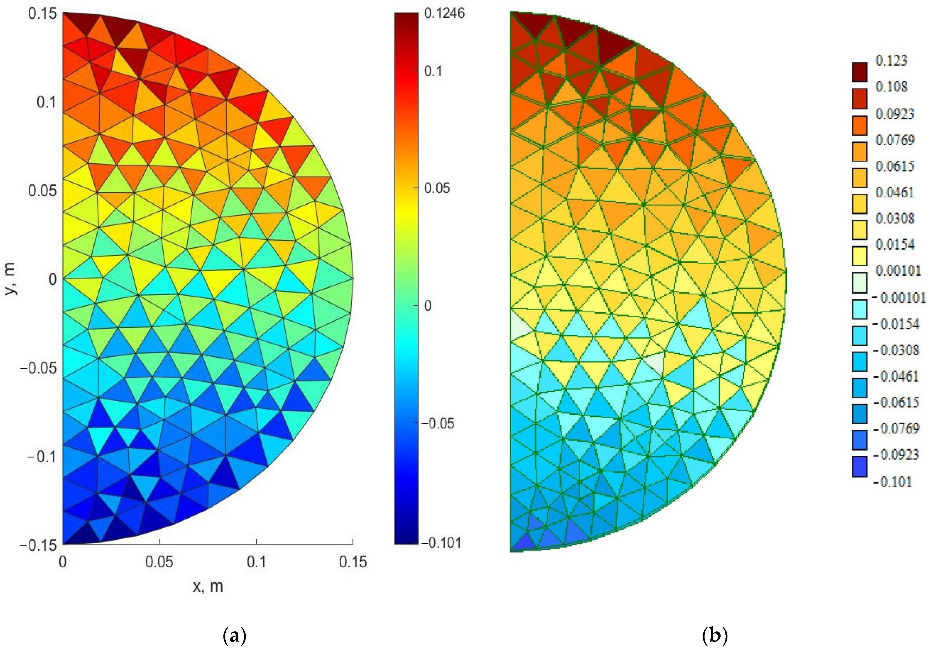
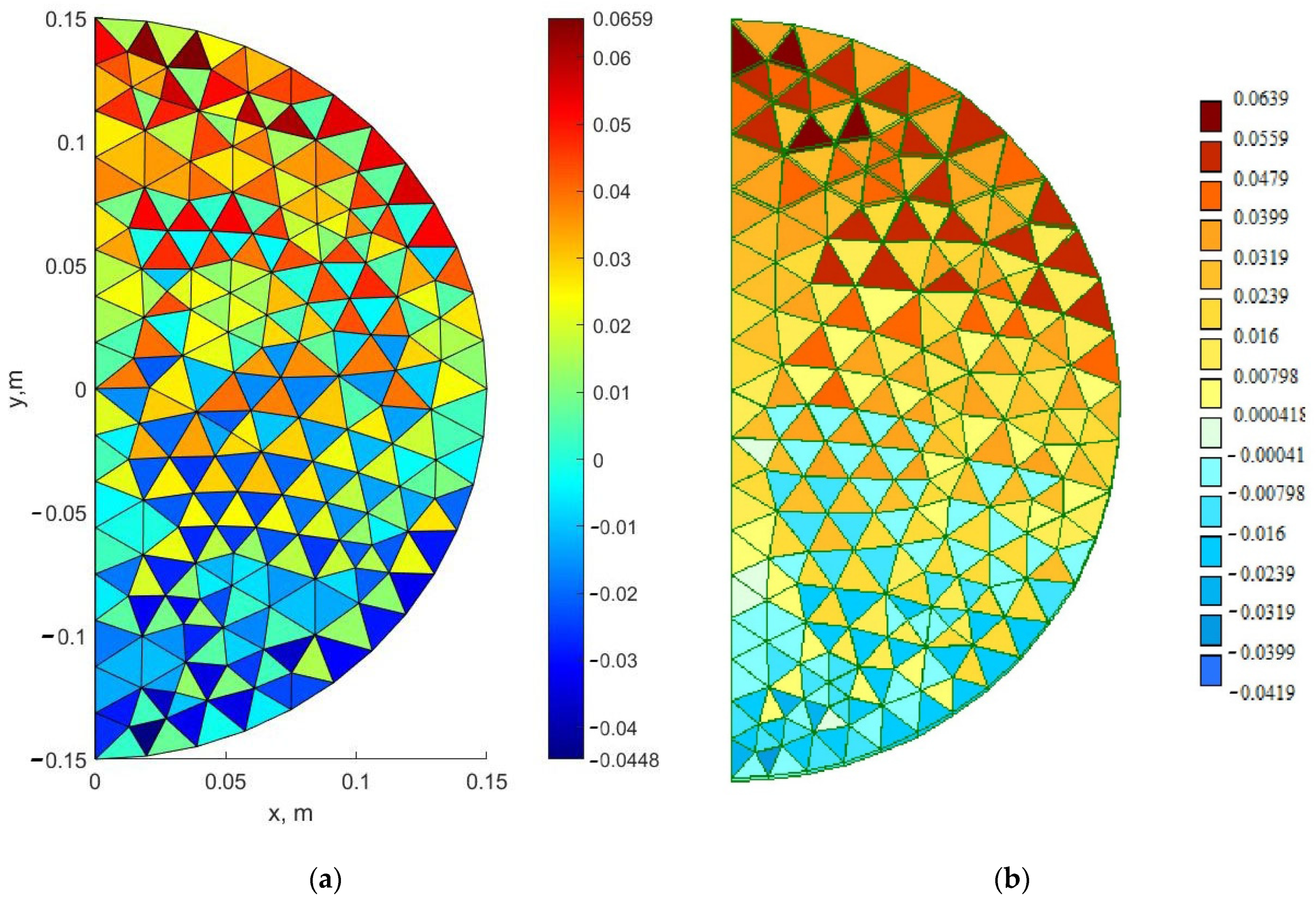
The resulting mosaics of stresses σz, σx, σy are shown in Figure 5, Figure 6 and Figure 7. A comparison of the maximum stress values in LIRA-SAPR and MATLAB is given in Table 1.
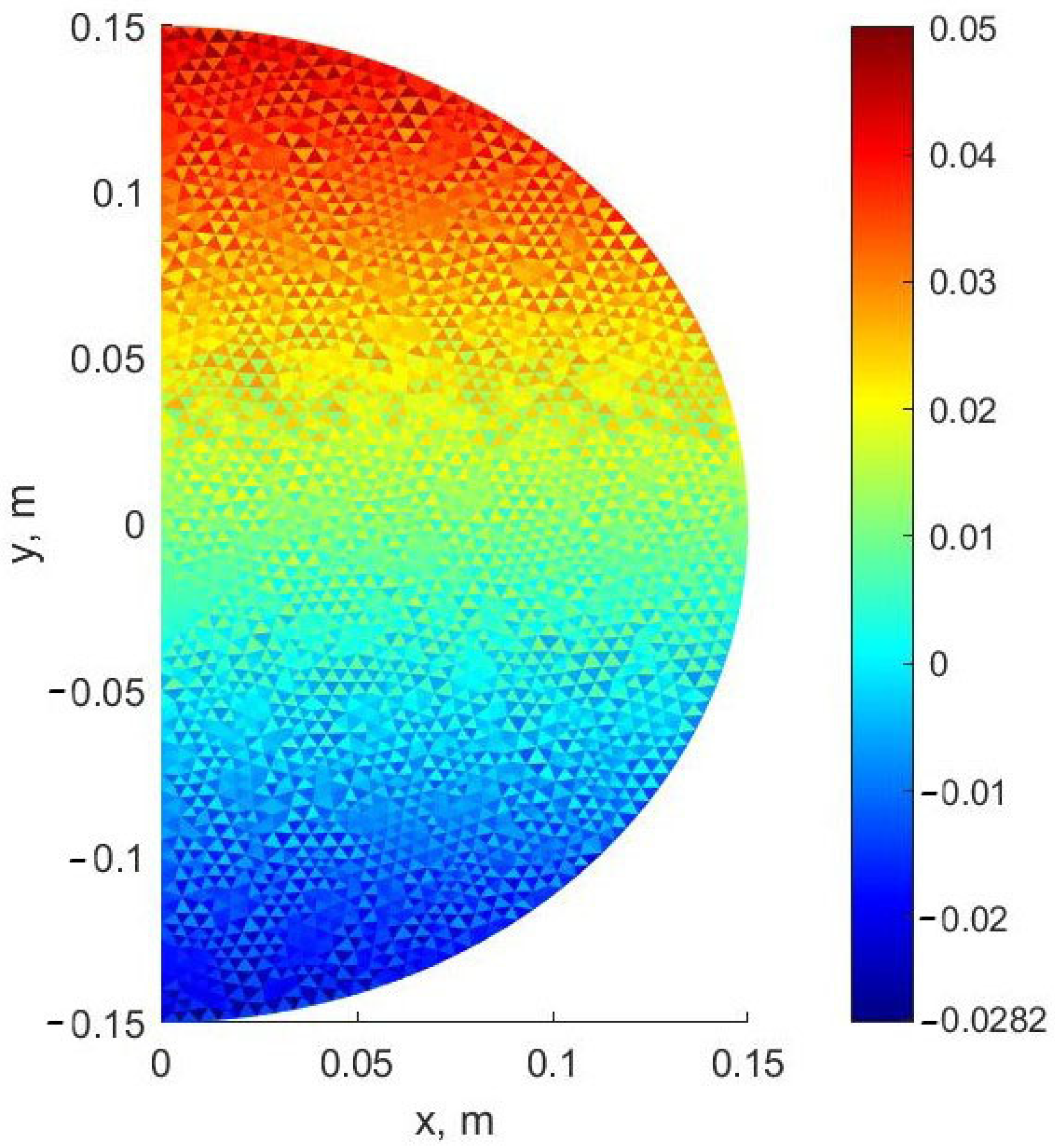
The scatter of stresses σy in neighboring elements is observed both when solving in the three-dimensional formulation in LIRA-SAPR, and when solving in the two-dimensional formulation in MATLAB. This is because the stresses σy are significantly lower than the stresses σz. In addition, the reason may be low approximation properties of simplex triangular elements. In the finer FE mesh, this scatter decreases (Figure 8). Calculation on the coarse mesh gives overestimated stress values, which goes into a safety margin.
Also, the developed methodology and software was tested on experimental data presented in the works of A.L. Krishan and A.I. Sagadatov [31,32,33]. The comparison with the experimental data for two series of columns with an outer diameter of the concrete core of 159 and 219 mm and wall thickness of 6 and 8 mm, can be introduced respectively.
Table 2 presents the experimental values of the ultimate loads N u , exp , the theoretical values N u , t h e o r were obtained, as well as the values of the ultimate loads N u , b s , calculated without taking into account the lateral compression of the core.
For all specimens, the modulus of elasticity of steel was taken equal to Es = 2∙× 105 MPa and the yield strength was assumed to be Ry = 400 MPa. For the samples 1–3, the initial modulus of elasticity of concrete Eb0 and tensile strength Rbt were taken Eb0 = 3 × 10⁴ MPa and Rbt = 1.8 MPa. For the samples 4–6: Eb0 = 3.7 × 10⁴ MPa and Rbt = 2.25 MPa.
From Table 2, it can be seen that the agreement of the results is quite good; the greatest deviation of the ultimate loads theoretical values from the experimental ones is
δ = | N u , exp N u , t h e o r | N u , exp 100 % = | 1412 1430 | 1412 100 % = 1.3 % .
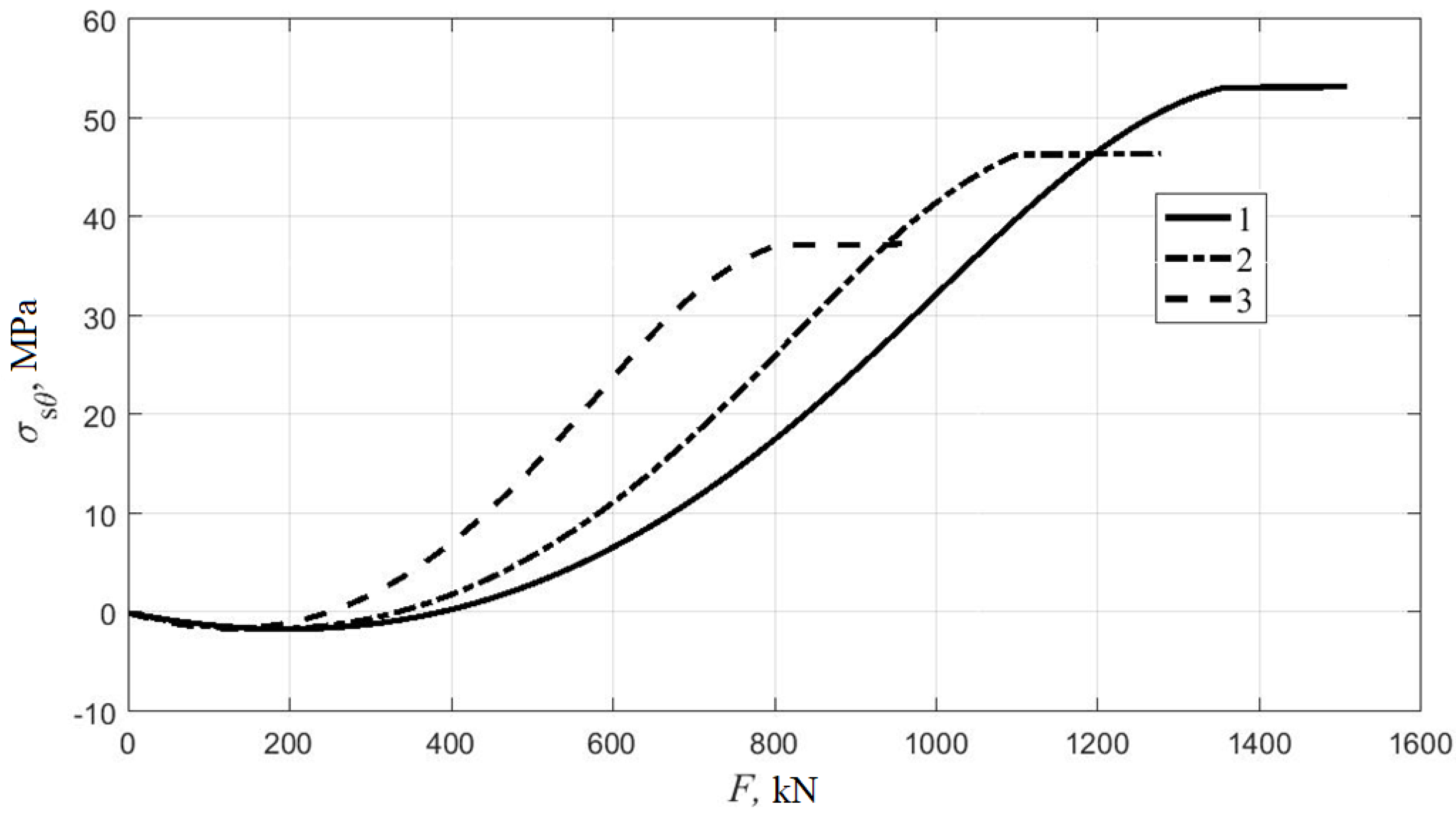
Figure 9 and Figure 10 show the theoretical graphs of changes in stresses σ at y = -R (at the point with the lowest absolute value of the compressive stresses σsz) and y = R (where the highest compressive stresses along z occur) depending on the load for columns 1–3 in Table 2.
From the presented graphs, it can be seen that—with an increase in eccentricity—the stresses σ decrease, which also indicates a reduction in the stresses of the lateral compression of concrete. This explains the fact that the area of effective operation of CFST columns is small eccentricities of the longitudinal force.

4. Discussion

The constructed model of CFST columns deformation is based on the general equations of the mechanics of a deformable solid and, unlike many existing approaches, does not contain empirical coefficients. The proposed technique makes it possible to model columns of not only circular but also annular, rectangular, hexagonal, and octagonal cross-sections. It is possible to determine the stresses in the cross-section for eccentric compression and bending. In contrast to empirical approaches when using the finite element method there are no restrictions on the composition of the concrete and the shell material. In the future, it is planned to conduct a study of the stress–strain state of columns of non-circular cross-section, as well as columns in a fiberglass shell.
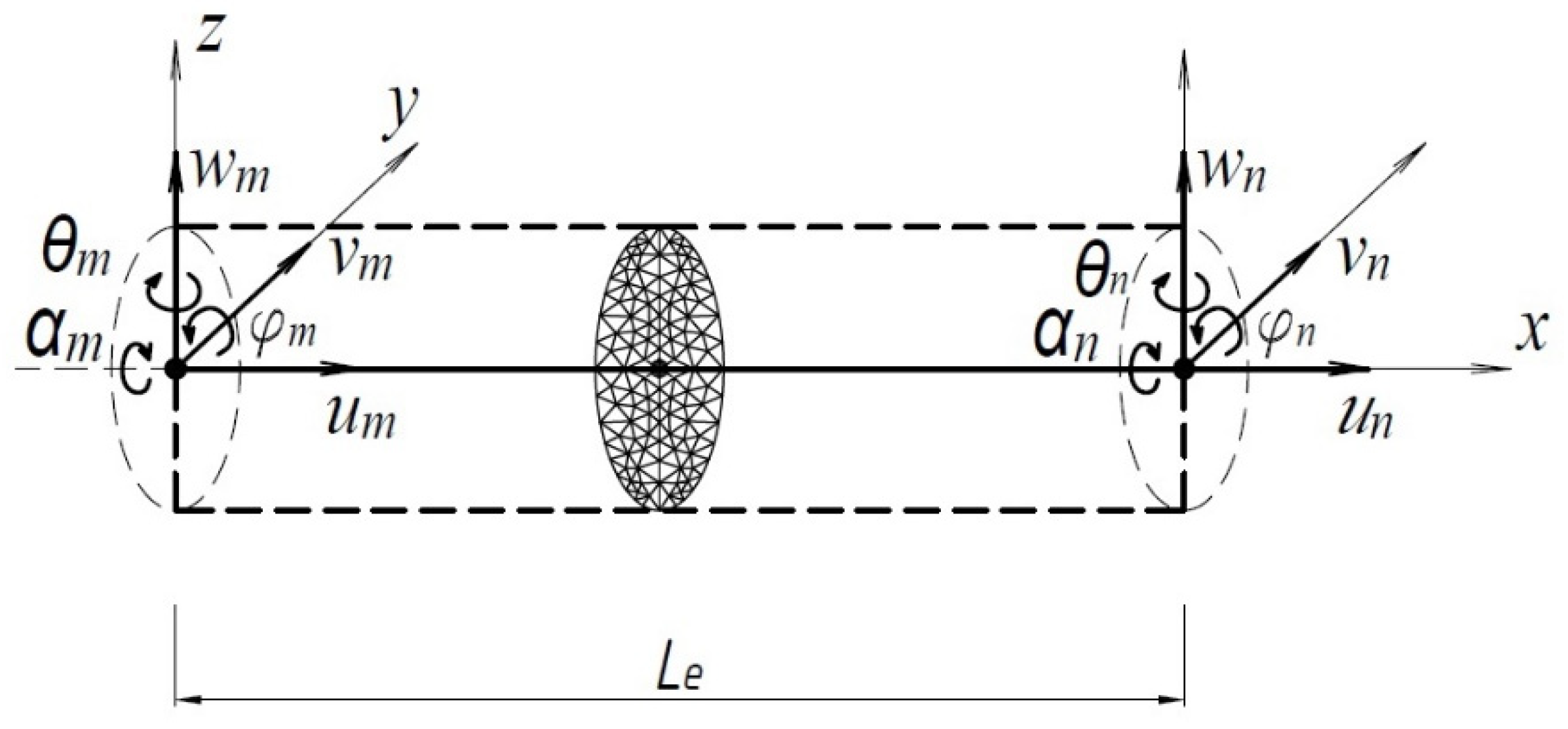
The disadvantage of the proposed model is that it does not consider the additional eccentricity of the longitudinal force arising from the deflection of the element. In other words, the proposed approach allows to the calculation of only short CFST columns. The composite finite element is currently developed for flexible columns that include the traditional beam finite element and the cross-section (Figure 11). When constructing the fundamental relationships, both physical and geometric nonlinearity will be taken into account.

5. Conclusions

1.
The method and software for determining the stress–strain state and calculating the bearing capacity of short CFST columns by reducing the three-dimensional problem to the two-dimensional one were developed. The proposed approach leads to significant savings in computational time in comparison with the calculation in the three-dimensional formulation. In the proposed approach, only the displacements of the nodes in the section plane xy and two additional variables ε z 0 and χ act as unknowns.
2.
The proposed method was verified by comparing the solution in the elastic formulation with the solution in the LIRA-SAPR finite element software package based on the three-dimensional model. With the same mesh density in the section plane discrepancy in stresses was 0.6% for σz, 1.6% for σx and 3.1% for σy.
3.
The developed method was also tested on the experimental data of A.L. Krishan and A.I. Sagadatov for six eccentrically compressed specimens with different eccentricities of the longitudinal force and diameters. The maximum discrepancy between the theoretical and experimental values of the ultimate load was 1.3%. These results also indicate the possibility of applying Geniev’s deformational theory of plasticity of concrete to the calculation of CFST columns.
4.
It was found that, with an increase in the eccentricity of the longitudinal force, the effect of concrete work under conditions of a triaxial stress state in CFST columns with a circular cross-section decrease. The increase in bearing capacity due to the work of concrete under conditions of a triaxial stress state for the samples with D = 159 mm was 19% at e/D = 0.065 and only 3% at e/D = 0.26. Thus, the area of effective work for columns of circular cross-section is small eccentricities of the longitudinal force.

Author Contributions

Conceptualization A.C., V.C. and B.Y.; Methodology A.C., A.B. and B.Y.; Software A.C., V.C. and K.K.; Validation A.C. and A.B.; Formal analysis A.C., V.C. and K.K.; Investigation A.C.; Resources A.C., A.B. and B.M.; Data curation A.C., A.B. and V.C.; Writing—original draft preparation A.C. and A.B.; Writing—review and editing, A.C. and A.B.; Visualization A.C., V.C. and K.K.; Supervision, A.C. and B.M.; Project administration, A.C., A.B. and B.M.; Funding acquisition, A.C., A.B. and B.M. All authors have read and agreed to the published version of the manuscript.

Funding

This research received no external funding.

Institutional Review Board Statement

Not applicable.

Informed Consent Statement

Not applicable.

Data Availability Statement

The study do not report any data.

Acknowledgments

The authors acknowledge to the administration of the Don State Technical University for support and financial assistance.

Conflicts of Interest

The authors declare no conflict of interest. The funders had no role in the design of the study, in the collection, analyses, or interpretation of data, in the writing of the manuscript, or in the decision to publish the results.

References

  1. Bai, Y.; Wang, J.; Liu, Y.; Lin, X. Thin-Walled CFST Columns for Enhancing Seismic Collapse Performance of High-Rise Steel Frames. Appl. Sci. 2017, 7, 53. [Google Scholar] [CrossRef] [Green Version]
  2. Zhou, X.; Liu, J. Application of Steel-tubed Concrete Structures in High-rise Buildings. Int. J. High-Rise Build. 2019, 8, 161–167. [Google Scholar] [CrossRef] [Green Version]
  3. Krishan, A.L.; Chernyshova, E.P.; Sabirov, R.R. Calculating the Strength of Concrete Filled Steel Tube Columns of Solid and Ring Cross-Section. Procedia Eng. 2016, 150, 1878–1884. [Google Scholar] [CrossRef] [Green Version]
  4. Krishan, A.L.; Astafeva, M.A.; Chernyshova, E.P. Strength Calculation of Short Concrete-filled Steel Tube Columns. Int. J. Concr. Struct. Mater. 2018, 12. [Google Scholar] [CrossRef]
  5. Dong, H.; Li, Y.; Cao, W.; Qiao, Q.; Li, R. Uniaxial compression performance of rectangular CFST columns with different internal construction characteristics. Eng. Struct. 2018, 176, 763–775. [Google Scholar] [CrossRef]
  6. Yang, Y.; Fu, F.; Bie, X. Behaviour of rectangular RACFST slender columns under eccentric compression. J. Build. Eng. 2021, 38, 102236. [Google Scholar] [CrossRef]
  7. Chen, J.; Chan, T.-M.; Chung, K.-F. Design of square and rectangular CFST cross-sectional capacities in compression. J. Constr. Steel Res. 2021, 176, 106419. [Google Scholar] [CrossRef]
  8. Qu, X.; Chen, Z.; Sun, G. Axial behaviour of rectangular concrete-filled cold-formed steel tubular columns with different loading methods. Steel Compos. Struct. 2015, 18, 71–90. [Google Scholar] [CrossRef]
  9. Qu, X.; Chen, Z.; Sun, G. Experimental study of rectangular CFST columns subjected to eccentric loading. Thin-Walled Struct. 2013, 64, 83–93. [Google Scholar] [CrossRef]
  10. Ma, D.Y.; Han, L.H.; Ji, X.; Yang, W.B. Behaviour of hexagonal concrete-encased CFST columns subjected to cyclic bending. J. Constr. Steel Res. 2018, 144, 283–294. [Google Scholar] [CrossRef]
  11. Xu, W.; Han, L.H.; Li, W. Performance of hexagonal CFST members under axial compression and bending. J. Constr. Steel Res. 2016, 123, 162–175. [Google Scholar] [CrossRef]
  12. Hassanein, M.F.; Patel, V.I.; Bock, M. Behaviour and design of hexagonal concrete-filled steel tubular short columns under axial compression. Eng. Struct. 2017, 153, 732–748. [Google Scholar] [CrossRef]
  13. Hassanein, M.F.; Patel, V.I. Round-ended rectangular concrete-filled steel tubular short columns: FE investigation under axial compression. J. Constr. Steel Res. 2018, 140, 222–236. [Google Scholar] [CrossRef]
  14. Fang, H.; Chan, T.M.; Young, B. Structural performance of concrete-filled cold-formed high-strength steel octagonal tubular stub columns. Eng. Struct. 2021, 239, 112360. [Google Scholar] [CrossRef]
  15. Krishan, A.L.; Rimshin, V.I.; Troshkina, E.A. Strength of Short Concrete Filled Steel Tube columns of Annular Cross Section. IOP Conf. Ser. Mater. Sci. Eng. 2018, 463, 022062. [Google Scholar] [CrossRef]
  16. Krishan, A.; Astafeva, M. Strength and Deformability of the Concrete Core of Precompressed Concrete Filled Steel Tube Columns of Annular Cross-Section. MATEC Web Conf. 2019, 278, 03002. [Google Scholar] [CrossRef]
  17. Krishan, A.L.; Narkevich, M.Y.; Sagadatov, A.I.; Rimshin, V.I. The strength of short compressed concrete elements in a fiberglass shell. Mag. Civ. Eng. 2020, 94, 3–10. [Google Scholar] [CrossRef]
  18. Jamaluddin, N.; Lam, D.; Dai, X.H.; Ye, J. An experimental study on elliptical concrete filled columns under axial compression. J. Constr. Steel Res. 2013, 87, 6–16. [Google Scholar] [CrossRef] [Green Version]
  19. Uenaka, K. Experimental study on concrete filled elliptical/oval steel tubular stub columns under compression. Thin-Walled Struct. 2014, 78, 131–137. [Google Scholar] [CrossRef]
  20. Fu, G.; Fu, G.; Yu, C.; Li, S.; Wang, F.; Yang, F. Behaviour of rectangular concrete-filled steel tubular slender column with unequal wall thickness. Eng. Struct. 2021, 236, 112100. [Google Scholar] [CrossRef]
  21. Weerasinghe, K.A.B.; Gamage, J.C.P.H.; Fawzia, S.; Thambiratnam, D.P. Experimental investigation on flexural behaviour of vertically-curved circular-hollow steel sections strengthened with externally bonded carbon fibre reinforced polymer. Eng. Struct. 2021, 236, 112040. [Google Scholar] [CrossRef]
  22. Gao, H.; Zhang, L.; Xu, S.; Wang, Q.; Wen, S.; Wang, Y. Study on the mechanical property of low magnesia ore high strength concrete-filled steel tubular columns. J. Phys. Conf. Ser. 2021, 1904, 012021. [Google Scholar] [CrossRef]
  23. Grigoryan, M.N.; Urvachev, M.; Chepurnenko, A.; Polyakova, T. Determination of the ultimate load for centrally compressed concrete filled steel tubular columns based on the deformation theory of plasticity. IOP Conf. Ser. Mater. Sci. Eng. 2020, 913, 022069. [Google Scholar] [CrossRef]
  24. Mailyan, D.; Mailyan, L. Ecologically safe and techno economically efficient reinforced concrete constructions of equal resistance. MATEC Web Conf. 2016, 73, 04020. [Google Scholar] [CrossRef] [Green Version]
  25. Mailyan, L.R.; Stel’makh, S.A.; Shcherban, E.M.; Khalyushev, A.K.; Smolyanichenko, A.S.; Sysoev, A.K.; Parinov, I.A.; Cherpakov, A.V. Investigation of Integral and Differential Characteristics of Variatropic Structure Heavy Concretes by Ultrasonic Methods. Appl. Sci. 2021, 11, 3591. [Google Scholar] [CrossRef]
  26. Beskopylny, A.; Kadomtseva, E.; Meskhi, B.; Strelnikov, G.; Polushkin, O. Influence of the Cross-Sectional Shape of a Reinforced Bimodular Beam on the Stress-Strain State in a Transverse Impact. Buildings 2020, 10, 248. [Google Scholar] [CrossRef]
  27. Mailyan, L.; Stel’makh, S.; Shcherban, E.; Komov, V.; Ferrarese, M.; Koposov, A. Calculation of Integral Properties of Vibrated and Centrifugated Concrete. Lect. Notes Civ. Eng. 2021, 150, 97–107. [Google Scholar] [CrossRef]
  28. Ouyang, Y.; Kwan, A.K.H. Finite element analysis of square concrete-filled steel tube (CFST) columns under axial compressive load. Eng. Struct. 2018, 156, 443–459. [Google Scholar] [CrossRef]
  29. Geniev, G.; Kissuk, V.; Tupin, G. Theory of Plasticity of Concrete and Reinforced Concrete; Stroyizdat: Moscow, Russia, 1974. [Google Scholar]
  30. Structural Engineering Software | Liraland Group. Available online: https://www.liraland.com/ (accessed on 5 December 2021).
  31. Sagadatov, A.I. Stress-Strain State of Compressed Concrete Filled Steel Tubular Elements with an Internal Steel Core. Ph.D. Thesis, Nosov Magnitogorsk State Technical University, Magnitogorsk, Russia, 2006. [Google Scholar]
  32. Narkevich, M.Y.; Sagadatov, A.I. Strength and deformation property enhancement of compressed steel tube-concrete elements using super concrete and thin-shell structure. IOP Conf. Ser. Mater. Sci. Eng. 2019, 687, 033031. [Google Scholar] [CrossRef]
  33. Krishan, A.L.; Astafyeva, M.A.; Chernyshova, E.P. Strength of Axially Loaded Concrete Filled Steel Tube Elements of Self-Stressing Concrete. Key Eng. Mater. 2018, 792, 160–165. [Google Scholar] [CrossRef]
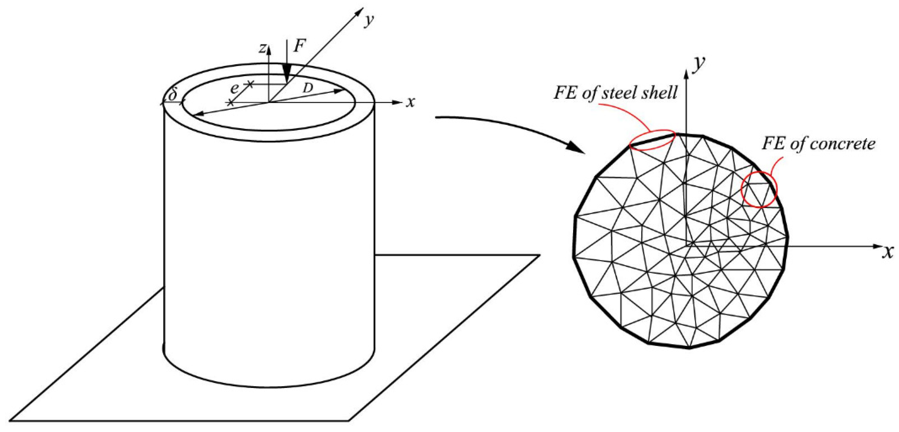
Figure 1. Calculation scheme.
Applsci 11 11645 g001
Figure 2. Plane triangular FE for concrete modeling.
Applsci 11 11645 g002
Figure 3. One-dimensional two-node FE for modeling the steel shell.
Applsci 11 11645 g003
Figure 4. Calculation scheme in LIRA SAPR software.
Applsci 11 11645 g004
Figure 5. Mosaic of stresses σz (MPa): (a) MATLAB; (b) LIRA-SAPR.
Applsci 11 11645 g005
Figure 6. Mosaic of stresses σx (MPa): (a) MATLAB; (b) LIRA-SAPR.
Applsci 11 11645 g006
Figure 7. Mosaic of stresses σy (MPa): (a) MATLAB; (b) LIRA-SAPR.
Applsci 11 11645 g007
Figure 8. Mosaic of stresses σy (MPa) for the finer FE mesh in MATLAB.
Applsci 11 11645 g008
Figure 9. Dependence of stresses σ at y =R on load.
Applsci 11 11645 g009
Figure 10. Dependence of stresses σ at y = R on load.
Applsci 11 11645 g010
Figure 11. Combined finite element of a CFST column.
Applsci 11 11645 g011
Table 1. Comparison of maximum stresses in LIRA-SAPR and MATLAB.
σz, MPaσx, MPaσy, MPa
MATLAB5.230.1250.0659
LIRA-SAPR5.20.1230.0639
Table 2. Comparison of experimental results with theoretical values of ultimate loads.
Sample NumberD, mmδ, mmRb, MPae/DNu,exp, kNNu,theor, kNNu,bs, kNNu,theor/Nu,bs
1159622.00.0651412143012001.19
2159622.50.131213121010601.14
3159622.30.269589509201.03
4219832.50.0652911291127801.05
5219830.50.132508251523651.06
6219832.10.261945195018701.04
Publisher’s Note: MDPI stays neutral with regard to jurisdictional claims in published maps and institutional affiliations.