Article

Design of Optical Free-Form Surface Milling Machine Based on Mechanical Shunt and Dynamic Analysis

School of Mechanical Engineering and Automation, Northeastern University, No. 3-11, Wenhua Road, Heping District, Shenyang 110819, China
*
Author to whom correspondence should be addressed.
Appl. Sci. 2021, 11(24), 11764; https://doi.org/10.3390/app112411764
Submission received: 24 September 2021 / Revised: 23 November 2021 / Accepted: 6 December 2021 / Published: 10 December 2021

Abstract

:
An optical free-form surface milling machine is designed according to the process characteristics and cutting force of optical components manufacturing. The Z-axis column of the milling machine is designed by a mechanical shunt. In this paper, based on the principle of multibody dynamics (MBD), a virtual prototype (VP) of the optical free-form surface milling machine was established by the ADAMS software. The Z-axis characteristics of the milling machine were simulated and studied, and a modal analysis was carried out to obtain the natural frequencies and vibration modes of the milling machine. The simulation results show that the Z-axis of the milling machine has excellent dynamic characteristics when the gravity balance device is not working. The average torque of the Z-axis motor is 0.5 N·m when the gravity balance device is working, the average torque of the Z-axis motor is 0.1 N·m, and the average torque is reduced by 80%; therefore, the gravity balance device can obviously lower the load of the Z-axis motor, and improve the efficiency of the milling machine.

1. Introduction

In the whole process chain of optical free-form surface machining, precision milling has a great influence on the surface and sub-surface quality of optical free-form surfaces, and its machining effect will directly determine the efficiency and feasibility of subsequent machining such as grinding and polishing. Therefore, the development of an optical free-form surface milling machine has become one of the key factors to improve the manufacturing ability of an optical free-form surface, and the coupling of high stiffness, large damping and long-term stability in the design of an optical free-form surface milling machine have also made it one of the most complex and risky engineering problems.
The structural dynamic performance of machine tools is a key factor that affects the machining precision and productivity. Structural design optimization is a type of crucial approach to improve the dynamic performance of machine tool structures and maximize the utilization ratio of materials [1,2,3]. Szymon Wojciechowski et al. [4] analyzed the influence of machining process parameters on milling dynamics. Eneko Gomez-Acedo et al. [5,6] presented a methodology of a thermal distortion compensation system for the large machine tools design; this method can greatly compensate the thermal deformation error of the machine tool. S. Wojciechowski et al. [7] evaluated the surface roughness during precise ball end milling of low hardened alloy steel. The traditional mode of production for machine tools (for example, the cycle of design, manufacture, experiment, and adjustment) cannot meet the requirements. Fortunately, the development of computer simulation technology and virtual machine tools provides a possible solution to this problem. The virtual machine tool is a simulation of the entire machine tool. It involves the structure of the machine tool and a computer numerical control system. Research into the virtual machine tools has attracted more and more attention at research institutes [8,9]. Using the virtual machine tool model, we can obtain the kinematics and structural dynamics, which notably influence the performance of machine tools. To meet all the requirements of the virtual machine tool in the best possible way, an accurate physical prototype must be established first. In the past decades, many studies have been performed on the issue. These studies are generally based on one of the following three models: finite element method (FEM) [10,11,12,13,14], multibody simulation [15,16,17], and discrete mass-spring-damper models [18,19,20]. In addition, Zaeh and Seidl [21] presented a method for modeling machine tools by integrating the finite element method with multibody simulations. Because of the complexity of the machine tool’s structure, a hybrid theoretical-experimental modeling method has been proposed in previous studies [22].
Dynamic design combined with static design has become an inevitable trend in the development of modern machine tool design. Because the characteristic parameters of the joint surface have a significant impact on the performance of the machine tool, the research on the identification technology of the joint surface parameters has become very important. This includes the input of the joint surface parameters to the virtual prototype for performance information, and comparison with the data obtained from the physical prototype experiment to determine the accuracy of the virtual prototype model. There are few reports on the impact of gravity balance device on machine tool dynamics. So, this paper establishes a virtual prototype of the optical free-form surface milling machine, based on the model, the influence of the gravity balance device on the Z-axis dynamics of the milling machine was studied from a quantitative and qualitative perspective.
The optical free-form surface in the paper is a kind of precise optical component used in the optical system. This kind of optical surface requires nano-scale roughness and ten-nano-scale profile; it also requires a milling machine with excellent dynamic performance. Based on ergonomics theory and product modeling design theory, an optical free-form surface milling machine using a mechanical shunt design for Z-axis columns is developed and a virtual prototype (VP) of the optical free-form surface milling machine is established based on the basic theory of multibody dynamics (MBD). The optical free-form surface milling machine is a five-axis linkage machine tool. The Z-axis load characteristics of the optical free-form surface milling machine is analyzed. The natural frequencies of the optical free-form surface milling machine adopting different structural schemes and material schemes are obtained. The installation of a gravity balance device can effectively reduce the load of the Z-axis motor, and improve the efficiency of the milling machine. The obtained dynamic performance information of the optical free-form surface milling machine provides a theoretical reference for the selection of manufacturing process parameters, and, at the same time, provides data for the design of Z-axis components and the control system. The virtual prototype technology used in the design stage of a machine tool can obtain more accurate dynamic characteristic information than traditional design methods of a machine tool.

2. Design of Optical Free-Form Surface Milling Machine

Figure 1 shows the component details of the main structure of optical free-form surface milling machine when the Z-axis motor is installed on the roof. The number of Z-axis columns is four, which are installed on the four corners of the milling machine bottom plate. The top of the Z-axis column is connected to the milling machine roof. The milling machine bottom plate is installed on the milling machine base, the cradle workbench is installed on the center position of milling machine bottom plate, and the optical free-form surface component is installed on the cradle workbench through a workpiece fixture. The upper surface of the milling machine bottom plate is provided with a milling waste liquid collection tank, the bottom of the milling waste liquid collection tank is provided with a waste liquid collection hole, and the milling waste liquid is discharged through the waste liquid collection hole. The Z-axis column and the slide carriage is connected by the Z-axis guide rail slider. The Z-axis guide rail slider is installed on the Z-axis guide rail slider mounting groove. The Z-axis screw and the slide carriage are connected by the Z-axis screw nut. The two-dimensional main motion platform is installed on the center position of the milling machine roof, the oil cylinder rod of the gravity balance device sequentially passes through the two-dimensional main motion platform and the milling machine roof to connect with the two-dimensional follow-up motion platform, and the two-dimensional follow-up motion platform is installed on the center position of the slide carriage. The bottom of the slide carriage is equipped with the Y-axis motion mechanism, the bottom of Y-axis motion mechanism is installed on the X-axis motion mechanism, and the bottom of the X-axis motion mechanism is connected to the spindle components through the headstock. The slide carriage is driven by four Z-axis motors set on four Z-axis columns, respectively.
Gravity transfer path refers to the force flow path of the suspended gravity in the milling machine structure, the lifting force of the gravity balance device is the sum of the gravity of slide carriage, X-axis motion mechanism, Y-axis motion mechanism, and spindle components. Figure 2a shows the gravity transfer path of the optical free-form surface milling machine, where the Z-axis motor is installed on the roof. When the gravity balance device is not working, most gravity of the suspended part of milling machine is transmitted from the inside of the column and a small part is transmitted from the outside of the column. Figure 2b shows the gravity transfer path of optical free-form surface milling machine, where the Z-axis motor is installed on the roof. When the gravity balance device is working, most gravity of the suspended part of milling machine is transmitted from the outside of the column and a small part is transmitted from the inside of the column. Figure 2c shows the gravity transfer path of the optical free-form surface milling machine, where the Z-axis motor is installed on the column. When the gravity balance device is not working, the gravity of the suspended part of milling machine is all transmitted from the inside of the column. Figure 2d shows the gravity transfer path of the optical free-form surface milling machine, where the Z-axis motor is installed on the column. When the gravity balance device is working, the gravity of the suspended part of milling machine is all transmitted from the outside of the column.
Figure 3a is the working principle of a fixed gravity balance device. The fixed gravity balance device is composed of an oil cylinder and its connecting components. The fixed gravity balance device can balance the gravity of the suspended part of the milling machine. However, due to the movement of the X-axis and Y-axis of the milling machine, the gravity center of the suspended part of milling machine changes constantly, and the gravity moment generated will affect the milling machine precision. Figure 3b is the working principle of the two-dimensional motion gravity balance device. The two-dimensional motion gravity balance device is composed of an oil cylinder and its connecting components, a two-dimensional main motion platform and a two-dimensional follow-up motion platform. The two-dimensional main motion platform is composed of the X-axis main motion platform and the Y-axis main motion platform, which can do the main motion in the XY plane. The number of X-axis, Y-axis guide rail sliders and X-axis, Y-axis motor screw mechanism of the two-dimensional main motion platform is two, respectively, and they are arranged symmetrically on both sides of the oil cylinder axis. The two-dimensional follow-up motion platform is composed of the X-axis follow-up motion platform and the Y-axis follow-up motion platform. The two-dimensional main motion platform drives the two-dimensional follow-up motion platform move in the XY plane. The number of X-axis, Y-axis guide rail sliders of the two-dimensional follow-up motion platform is two, respectively, and they are symmetrically arranged on both sides of the oil cylinder axis. Since the Z-axis slide carriage does not participate in the X-axis and Y-axis movements, the motion travels of the X-axis and Y-axis of the two-dimensional main motion platform are smaller than the X-axis and Y-axis motion travels of the milling machine, respectively. Because of the installation of the X-axis motion mechanism of the milling machine is under the Y-axis motion mechanism, the X-axis motion travel of the two-dimensional main motion platform is smaller than the Y-axis motion travel. When working, the two-dimensional main motion platform moves according to the position of the calculated gravity center, ensuring the gravity center of the suspended part of the milling machine is always on the axis of oil cylinder. The two-dimensional motion gravity balance device compared with the fixed gravity balance device cannot only balance the gravity of the suspended part of milling machine, but also eliminate the influence of the gravity moment on the precision of the milling machine. However, the number of motion axes of the milling machine is large, so the control system is more demanding.
The Z-axis motor is installed on the roof to interconnect the internal frame and external frame of the milling machine, which can increase the static and dynamic rigidity of the milling machine, but will produce a mechanical backflow effect (a small part of the gravity will flow out from the relative path) and reduce the precision of the Z-axis. The Z-axis motor installed on the column will not produce a mechanical backflow effect, so the Z-axis precision is high.

3. Function Description of Optical Free-Form Surface Milling Machine

3.1. Features of Optical Free-Form Surface Milling Machine

The main body size of optical free-form surface milling machine is 1200 × 1400 × 2000 mm, X-axis, Y-axis and Z-axis travel are 400 mm, 400 mm and 280 mm, respectively. The Z-axis column is made by dividing the upper part into two to form two columns sharing the lower part of the Z-axis column. The column on the inner side is provided with a Z-axis guide rail slider mounting groove, and the column on the outer side is connected to the roof of milling machine, the connecting surface of the outer column and the roof is higher than the upper end surface of the inner column. A milling machine foundation should have a vibration isolation device [23], working under constant temperature and humidity conditions.

3.2. Advantages of Optical Free-Form Surface Milling Machine

The Z-axis of the milling machine is a closed structure and a gravity balance device is provided. The milling machine has good stiffness, strength and stability. The gravity of the upper part of milling machine flows out partly from the Z-axis column without affecting the precision of the Z-axis. When natural granite is used as machine tool structure material, the machine tool has excellent structural stability and precision retention after long-term natural aging, and the material has also excellent vibration damping and a low thermal expansion coefficient, which can improve the manufacturing precision of the optical free-form surface. The milling machine can enhance the manufacturing precision of the optical free-form surface when using a two-dimensional motion gravity balance device. The symmetrical design of the milling machine structure can reduce the influence of heat on manufacturing precision [6]. The mechanical state of each structural part is good.

4. Establishment and Simulation of Virtual Prototype for Optical Free-Form Surface Milling Machine

4.1. ADAMS Dynamics Equation

In ADAMS, the Cartesian coordinates of the mass center of the rigid body B and the Euler angles reflecting the orientation of the rigid body are used as generalized coordinates, namely, q = x , y , z , ψ , θ , ϕ T , let R = x , y , z T , γ = ψ , θ , φ T , q = R T , γ T T .
The coordinate transformation matrix between the component centroid reference coordinate system and the geodetic coordinate system is:
A g i = cos ψ cos φ sin ψ cos θ sin φ cos ψ sin φ sin ψ cos θ cos φ sin ψ sin θ sin ψ cos φ + cos ψ cos θ sin φ sin ψ sin φ + cos ψ cos θ cos φ cos ψ sin θ sin θ sin φ sin θ cos φ cos θ
Define a Euler rotation axis coordinate system, the three unit-vectors of the coordinate system are the axes of the above three Euler rotations, so the three axes are not perpendicular to each other. The coordinate transformation matrix from this coordinate system to the component centroid coordinate system is:
B = sin θ cos φ 0 cos θ sin θ cos φ 0 sin θ cos θ 1 0
The angular velocity expression of the component is:
ω = B γ
The variable ω e introduced in ADAMS is the component of the angular velocity in the Euler axis of rotation coordinate system:
ω e = γ
Considering the constraint equation, ADAMS uses the energy form of the first type Lagrangian equation with Lagrangian multipliers, to obtain the following equation:
d d t T q j T q j = Q j + i = 1 n λ i φ q j
T is the kinetic energy expressed in the generalized coordinate system, q j is the generalized coordinate, and Q j is the generalized force in the generalized coordinate direction. The last term involves the constraint equation and the Lagrange multiplier, which expresses the constraint reaction force in the generalized coordinate direction.
ADAMS further introduces a generalized momentum:
P j = T q j
A simplified expression of the constraint reaction force is:
C j = i = 1 n λ i φ q j
So, Equation (6) is simplified to:
P j T q j = Q j C j
We express Equation (8) as the direction of movement and the direction of rotation, respectively:
P R T q R = Q R C R
P γ T q γ = Q γ C γ
In Equation (9), P R = d d t T q R = d d t M R = M V , T q R = 0 .
Equation (9) is simplified to: M V = Q R C R
B contains the Euler angles. In order to simplify the derivation, ADAMS does not further derive P γ , but solves it as a variable. In this way, each component in ADAMS has the following variables and equations.
Among them, M is the mass matrix of the component, and J is the inertia matrix of the component in the center of mass coordinate system.
Variable:
V = V x , V y , V z T R = x , y , z T P γ = P ψ , P θ , P φ T ω e = ω ψ , ω θ , ω φ T γ = ψ , θ , φ T
Equation:
M V = Q R C R V = R P γ T q γ = Q γ C γ P γ = B T J B ω e ω e = γ
ADAMS can automatically establish the dynamic equations of the system (differential-algebraic equations):
P T q + Φ q T λ + H T F = 0 P = T q u = q Φ ( q , t ) = 0 F = f ( u , q , t )
Among them, P is the generalized momentum of the system, and H is the coordinate transformation matrix of the external force.

4.2. Virtual Prototype of Optical Free-Form Surface Milling Machine

ADAMS is a kind of virtual prototype analysis software. The optical free-form surface milling machine model is introduced into the ADAMS/View module to establish the virtual prototype of the Z-axis motor that is installed on the roof. The Z-axis characteristics of the milling machine are simulated and analyzed.
The type of solver used by the ADAMS software include a linear solver (CALAHAN solver and HARWELL solver), nonlinear solver, DAE solver [(SI2: GSTIFF, WSTIFF and CONSTANT_BDF), (SI1: GSTIFF, WSTIFF and CONSTANT_BDF) and (I3: GSTIFF, WSTIFF, DSTIFF and CONSTANT_BDF)] and ODE solver (ABAM solver and RKF45 solver). The selection of the integrator and the setting of the solver have a great influence on the simulation speed and accuracy. In ADAMS, GSTIFF I3 and GSTIFF SI2 are the most widely used integrators, among them, the calculation accuracy of the GSTIFF SI2 integrator is much higher than that of GSTIFF I3, but the calculation efficiency is lower. It is suitable for simulation calculation of this model and the accuracy of the solver is set to 1 × 10⁻⁵, the step size is 1 × 10⁻⁴.
In ADAMS, firstly, we set up the working environment including gravity options and unit options. Secondly, we add the component constraints of the model including the contact parameters, where the contact type of the Z-axis screw and the Z-axis screw nut, the Z-axis lead screw and the Z-axis bearing is the rotating pair (the contact stiffness between the Z-axis screw and the Z-axis screw nut is 3.1 × 10⁸ N/m, and the contact damping is 3.6 × 10³ N·s/m; the contact stiffness between the Z-axis lead screw and the Z-axis bearing is 4.4 × 10⁸ N/m, and the contact damping is 3.8 × 10³ N·s/m), the contact type of the Z-axis guide rail and the Z-axis slider is the moving pair (the contact stiffness between the Z-axis guide rail and the Z-axis slider is 2.37 × 10⁸ N/m, and the contact damping is 4.3 × 10³ N·s/m), the other contact type between contact surfaces is the fixed pair (the contact stiffness between the Z-axis column and the milling machine bottom plate is 5.05 × 10⁸ N/m, and the contact damping is 1.91 × 10⁴ N·s/m; the contact stiffness between the milling machine bottom plate and the milling machine base is 8.08 × 10⁹ N/m, and the contact damping is 3.06 × 10⁵ N·s/m). Thirdly, we define the materials of the milling machine components, the main structure material of milling machine is cast iron, the elastic modulus of cast iron is 120 GPa, the Poisson’s ratio is 0.25, and the density is 7300 kg/m3. Fourthly, we create the rotation speed of the Z-axis motor. Fifthly, we apply the balance force according to whether the gravity balance device is working or not. Sixthly, the milling machine needs to be softened when modeling flexible multibody model. Finally, the Z-axis characteristics of the milling machine can be dynamically simulated after the system model is successfully verified. Simulation results can be obtained in the ADAMS/PostProcessor module. Figure 4 is the virtual prototype of the optical free-form surface milling machine established through ADAMS.

4.3. Virtual Simulation of Optical Free-Form Surface Milling Machine

Since the milling machine spindle, X-axis motion mechanism and Y-axis motion mechanism are installed on the slide carriage, when the Z-axis motor drives the slide carriage, the spindle also moves at the same time. When the Z-axis motor rotates at a constant rotation speed (300 r/min), the gravity balance device is working and the flexible multibody model is used. Figure 5a shows the displacement curve of the spindle when the Z-axis moves 270 mm from the highest position downward; the type of curve is slash. Figure 5b shows the speed curve of the spindle, the average speed value is about 0.027 m/s, and it can be seen that the speed quickly reaches the average value and remains constant. Figure 5c shows the acceleration curve of the spindle, and it can be seen that the acceleration has a small fluctuation during the entire time period. The maximum fluctuation range is around 1 × 10⁻¹⁴ m/s2, so the Z-axis of the milling machine has excellent dynamic characteristics.
When the gravity balance device is working, the flexible multibody model is used. Figure 6a shows the X-direction projection curve of the Z-axis screw nut, the curve is a fully periodic and regularly fluctuating function, the fluctuation range is between 0° and minus 180°, and each fluctuation cycle time is very short. Figure 6b shows the Y-direction projection curve of the Z-axis screw nut, and the value is constant 0°. Figure 6c shows the Z-direction projection curve of the Z-axis screw nut, the curve is a fully periodic and regularly fluctuating function, the first fluctuation range is between 160° and minus 160°, the second fluctuation range is between 120° and minus 120°, and each fluctuation cycle time is very short. The three-dimensional projection curve of the Z-axis screw nut indirectly indicates the dynamic characteristics of the Z-axis screw; it will affect the driving precision of the Z-axis.
Figure 7a shows the torque curve of the Z-axis motor using the rigid multibody model when the gravity balance device is not working, the curve is a monotonically decreasing function, the maximum torque is about 0.6 N·m, the minimum torque is about 0.25 N·m, and the average torque is about 0.5 N·m. Figure 7b shows the torque curve of the Z-axis motor using the flexible multibody model when the gravity balance device is not working, the curve is a fully periodic and irregularly fluctuating function, the maximum torque is about 3.5 N·m, the minimum torque is close to 0 N·m, and the average torque is about 0.5 N·m. It can be seen that the rigid multibody model and the flexible multibody model have the approximate average value.
Figure 8a shows the load curve of the Z-axis end bearing using the rigid multibody model when the gravity balance device is not working, the curve is a monotonically decreasing function, the maximum force is about 3600 N, the minimum force is about 1500 N, and the average force is about 3000 N. Figure 8b shows the load curve of the Z-axis end bearing using the flexible multibody model when the gravity balance device is not working, the curve is a fully periodic and irregularly fluctuating function, the maximum force is about 22,500 N, the minimum force is close to 0 N, and the average force is about 3000 N. It can be seen that the rigid multibody model and the flexible multibody model have the approximate average value.
Figure 9a shows the torque curve of the Z-axis motor using the rigid multibody model when the gravity balance device is working, the curve is a monotonically decreasing function, the maximum torque is about 0.2 N·m, the minimum torque is about 0.025 N·m, and the average torque is about 0.1 N·m. Figure 9b shows the torque curve of the Z-axis motor using the flexible multibody model when the gravity balance device is working; the curve at the early stage is an irregularly fluctuating function, the curve at the late stage is close to constant, the maximum torque is about 1N·m, the minimum torque is close 0 N·m, and the average torque is about 0.1 N·m. It can be seen that the rigid multibody model and the flexible multibody model have the approximate average value.
Figure 10a shows the load curve of the Z-axis end bearing using the rigid multibody model when the gravity balance device is working, the curve is a monotonically decreasing function, the maximum force is about 1200 N, the minimum force is about 125 N, and the average force is about 750 N. Figure 10b shows the load curve of the Z-axis end bearing using the flexible multibody model when the gravity balance device is working; the curve at the early stage is an irregularly fluctuating function, the curve at the late stage is close to constant, the maximum force is about 6750 N, the minimum force is close to 0 N, and the average force is about 750 N. It can be seen that the rigid multibody model and the flexible multibody model have the approximate average value.
According to the above simulation analysis, it can be found that the gravity balance device can obviously lower the load of the Z-axis motor and its fluctuation range, and improve the efficiency of the milling machine. Figure 11 shows the value of the Z-axis motor torque and the Z-axis end bearing load when the gravity balance device is working or not.
From an energy point of view, the first few natural frequencies concentrate most energy of the milling machine vibration, which has a great influence on the manufacturing precision of a workpiece. Therefore, the low-order natural frequencies of the optical free-form surface milling machine under constraint condition is extracted. The material of the milling machine main structure is cast iron or natural granite. The elastic modulus of natural granite is 55 GPa, the Poisson’s ratio is 0.3, and the density is 2800 kg/m3. The lower surface of the milling machine is fully constrained. When the Z-axis motor is installed on the roof, the first nine mode shapes of the free-form surface milling machine are shown in Figure 12. Because the motion axes of the milling machine are installed on the internal frame, from the mode shapes, it can be seen that the first-order mode of the milling machine affecting the machining precision is the third order; the first, second, fourth and ninth-order vibration modes correspond to the vibration of the milling machine’s external frame, and the other vibration modes are the vibrations of the milling machine’s internal frame.
When the Z-axis motor is installed on the column, the first nine mode shapes of the free-form surface milling machine are shown in Figure 13.
The first nine natural frequencies and mode description of the optical free-form surface milling machine adopting different structural schemes and material schemes are shown in Table 1.
The first nine natural frequencies of the optical free-form surface milling machine adopting different structural schemes and material schemes are shown in Figure 14.

5. Conclusions

(1)
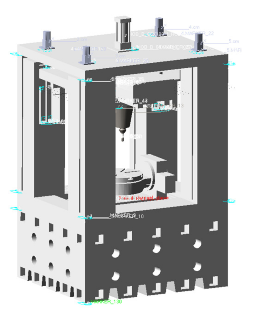
An optical free-form surface milling machine is creatively designed (Patent No.: ZL 2020 1 0008995. 1), and a virtual prototype (VP) of the optical free-form surface milling machine is established based on the basic theory of rigid multibody dynamics (RMBD) and the basic theory of flexible multibody dynamics (FMBD). The dynamic simulation research on the optical free-form surface milling machine is carried out according to the comparison method. The results show that the simulation results of the rigid multibody dynamics model and the flexible multibody dynamics model are numerically consistent. The virtual prototype technology used in the design stage of machine tools can obtain more accurate dynamic characteristic information than traditional design methods of machine tools.
(2)
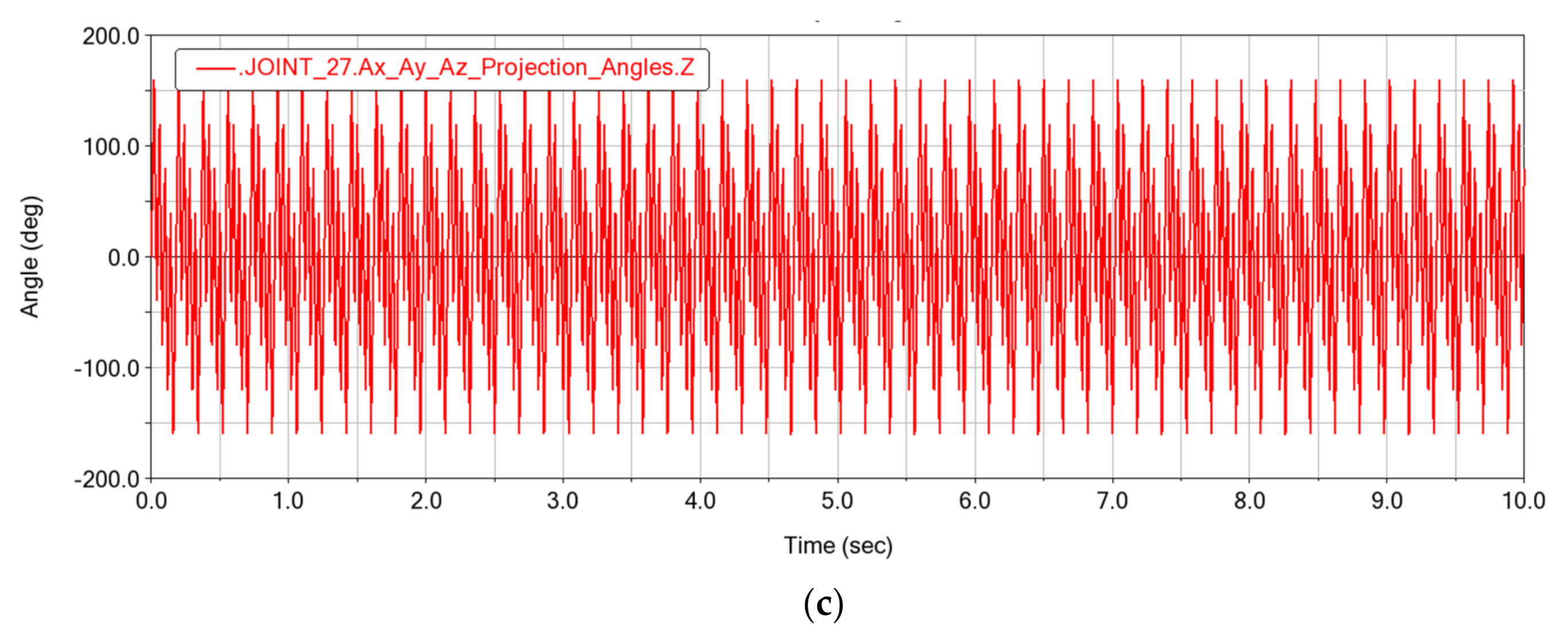
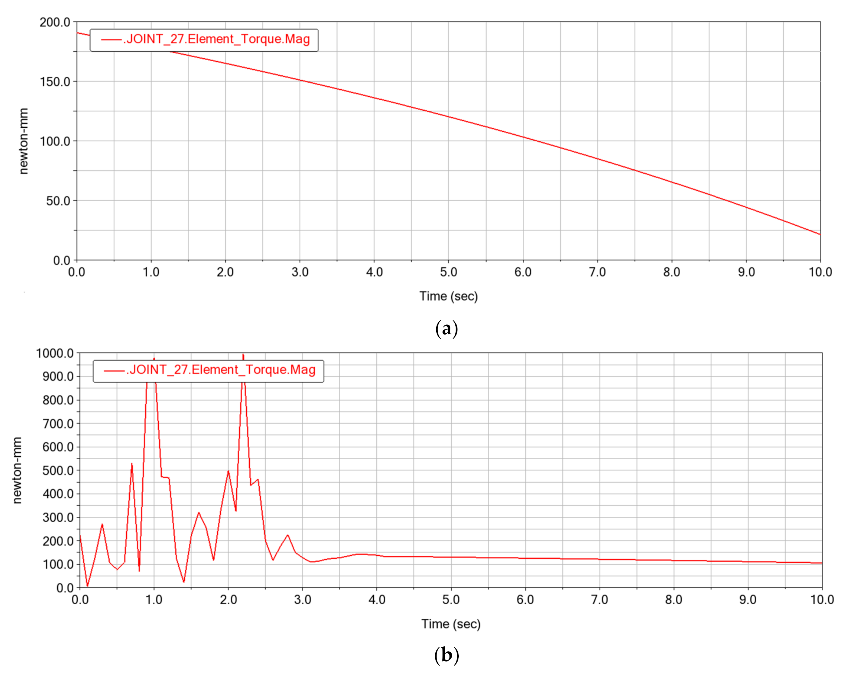
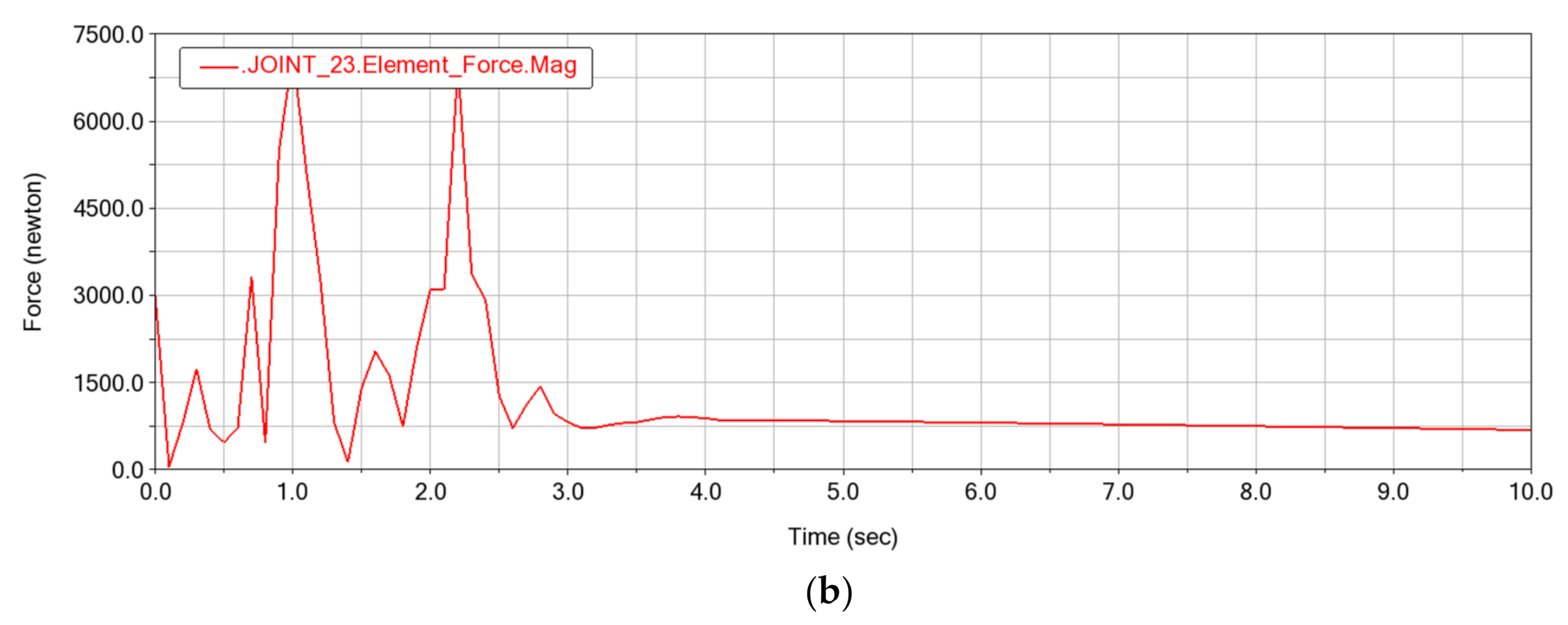
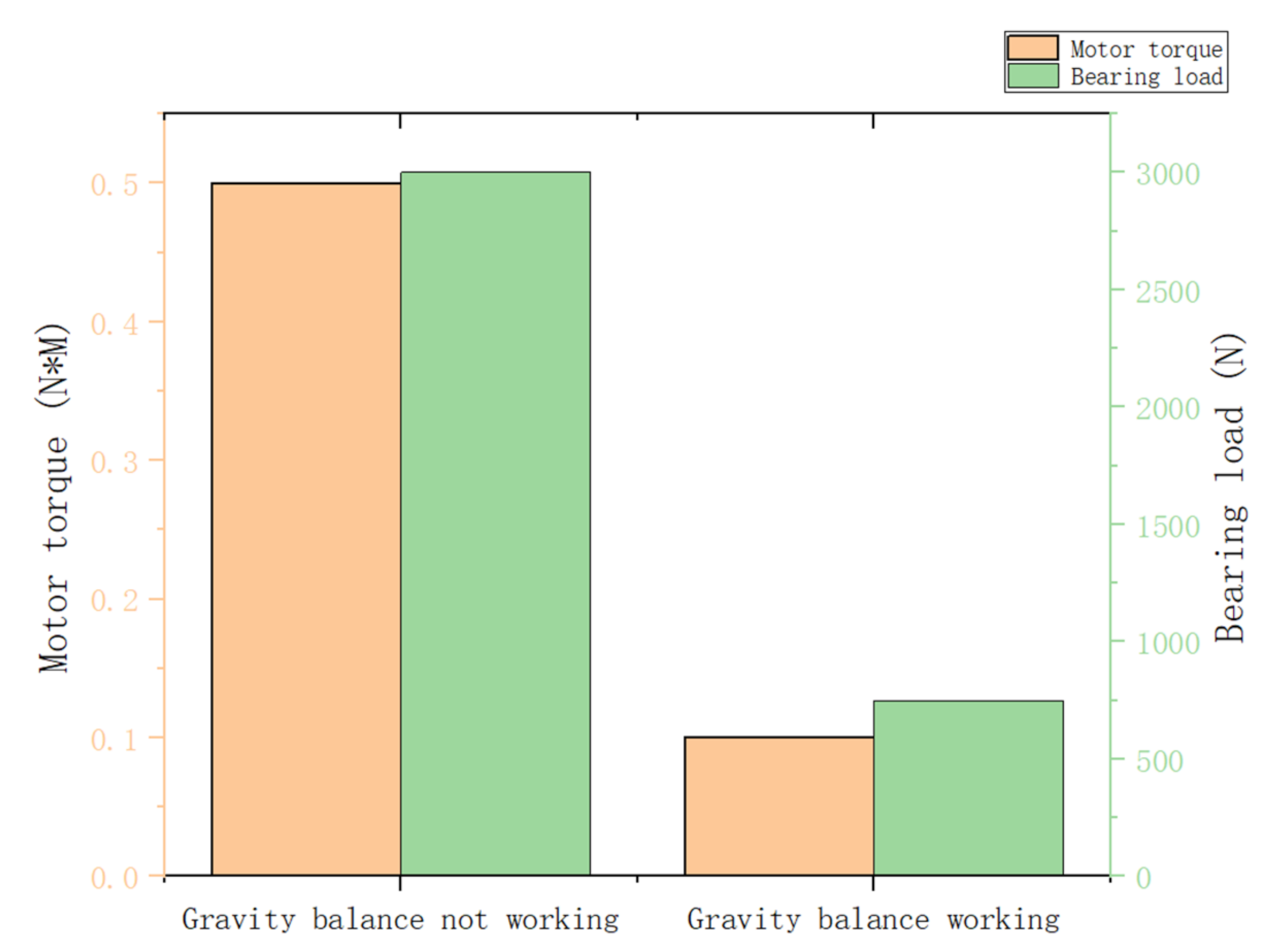
The Z-axis characteristics of optical free-form surface milling machine is analyzed. The simulation results show that the Z-axis of the optical free-form surface milling machine has excellent dynamic characteristics. The Z-axis load can be reduced effectively and the load fluctuation range becomes more gentle when the gravity balance device is working. When the gravity balance device is not working, the average torque of Z-axis motor is 0.5 N·m, when the gravity balance device is working, the average torque of Z-axis motor is 0.1 N·m, and the average torque is reduced by 80%. When the gravity balance device is not working, the average force of Z-axis end bearing is 3000 N, when the gravity balance device is working, the average force of Z-axis end bearing is 750 N and the average force is reduced by 75%. Therefore, the gravity balance device can suppress the load fluctuation of Z-axis and obviously improve the efficiency of the milling machine.
(3)
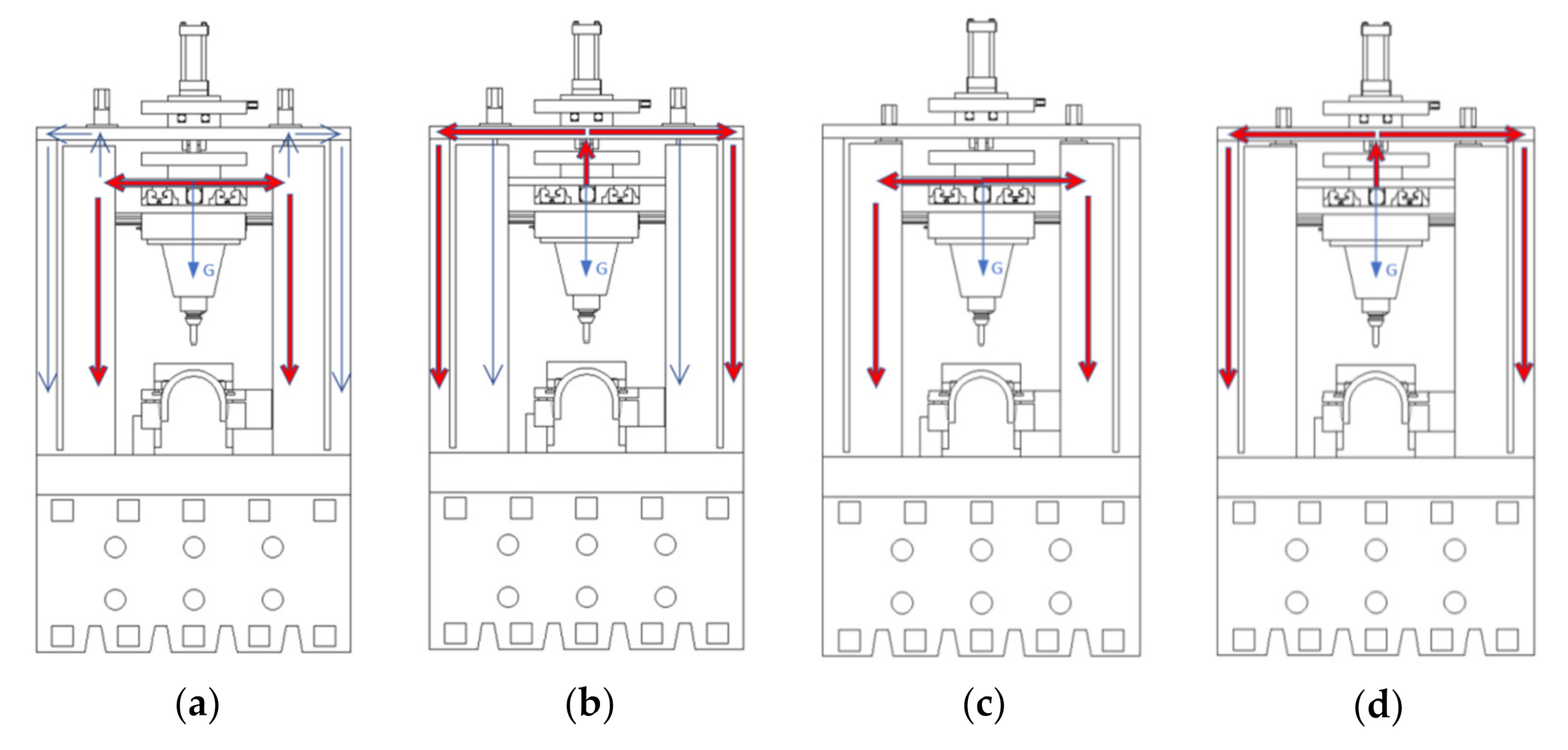
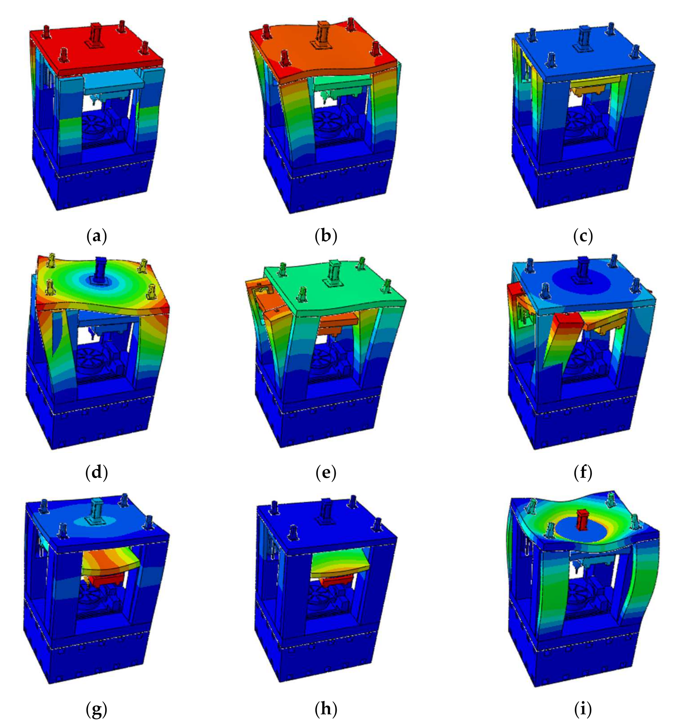
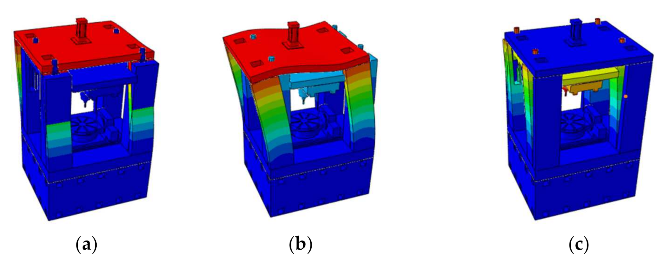
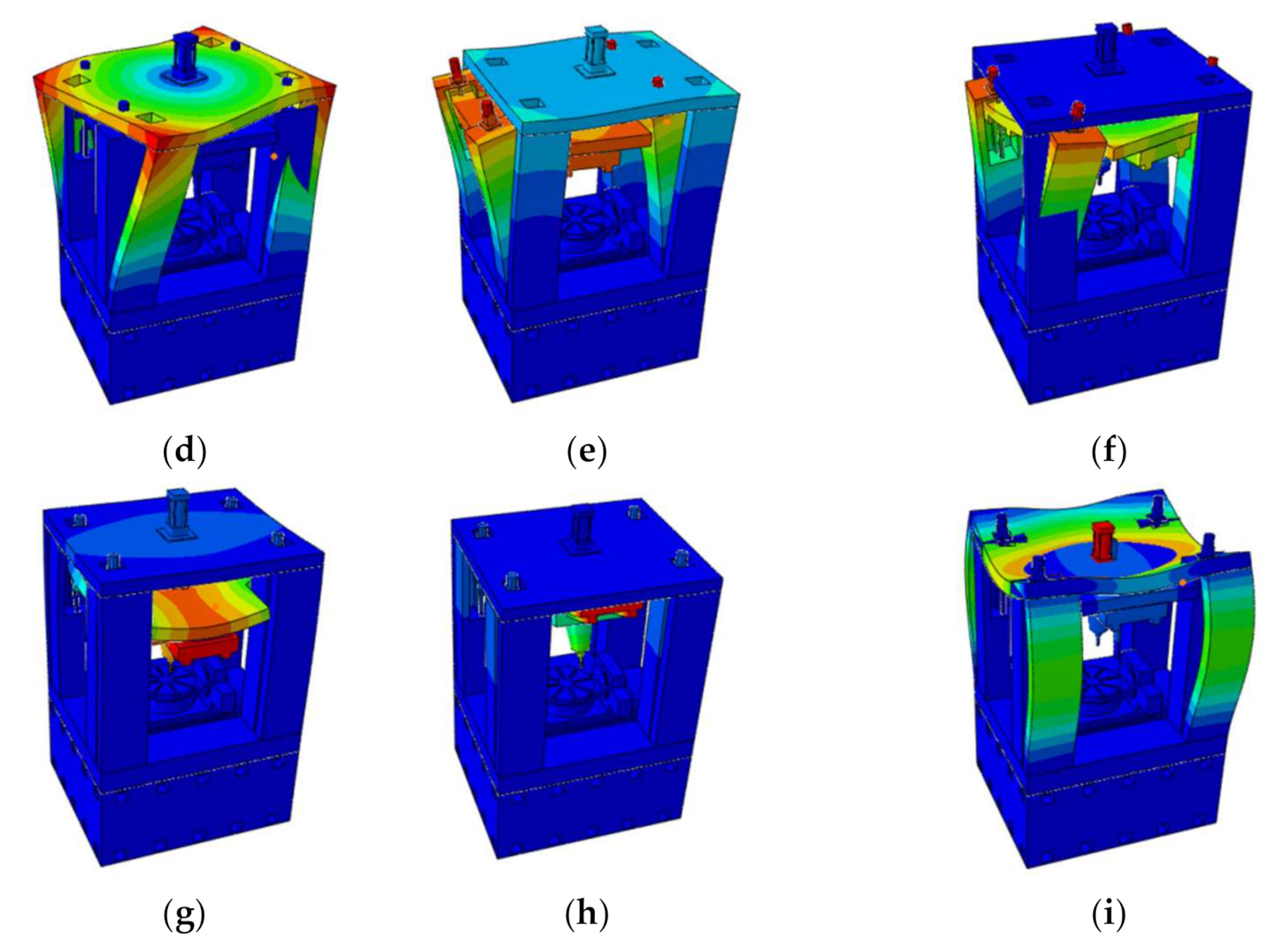
The natural frequencies of optical free-form surface milling machine adopting different structural schemes and material schemes are analyzed. The simulation results show that the first vibration mode of the milling machine affecting manufacturing precision is the third order, and the optimal dynamic characteristic design scheme is that the Z-axis motor is installed on the roof and the structure material is natural granite; the first natural frequency of milling machine affecting manufacturing precision is 68 HZ. The structure material using natural granite compared with cast iron can significantly improve the dynamic characteristics of the machine tool.
Soon we will build a physical prototype of a milling machine to verify the performances of the machine tool. Our future research plan will also focus on the influence of machining parameters on the surface integrity of optical free-form surface during milling, such as the study of milling chatter mechanism, and the influence of the milling machine dynamics on the machining quality of the optical free-form surface.

Author Contributions

Conceptualization, Q.L.; methodology, Q.L. and T.Y.; software, T.Y. and Z.W.; validation: T.Y. and Z.W.; writing—original draft preparation, Q.L. and W.W.; writing—review and editing: Q.L. and W.W. All authors have read and agreed to the published version of the manuscript.

Funding

This research was funded by the National Natural Science Foundation of China (2017YFA0701201) and the Northeastern University Postdoctoral Foundation (20210309).

Institutional Review Board Statement

Not applicable.

Informed Consent Statement

Not applicable.

Data Availability Statement

Not applicable.

Conflicts of Interest

The authors declare no conflict of interest.

References

  1. Möhring, H.C.; Brecher, C.; Abele, E.; Fleischer, J.; Bleicher, F. Materials in machine tool structures. CIRP Ann. Manuf. Technol. 2015, 64, 725–748. [Google Scholar] [CrossRef]
  2. Liu, S. Multi-objective optimization design method for the machine tool’s structural parts based on computer-aided engineering. Int. J. Adv. Manuf. Technol. 2015, 78, 1053–1065. [Google Scholar] [CrossRef]
  3. Shi, Y.; Zhao, X.; Zhang, H.; Nie, Y.; Zhang, D. A new top-down design method for the stiffness of precision machine tools. Int. J. Adv. Manuf. Technol. 2016, 83, 1887–1904. [Google Scholar] [CrossRef]
  4. Wojciechowski, S.; Mrozek, K. Mechanical and technological aspects of micro ball end milling with various tool inclinations. Int. J. Mech. Sci. 2017, 134, 424–435. [Google Scholar] [CrossRef]
  5. Gomez-Acedo, E.; Olarra, A.; Orive, J.; Lopez de la Calle, L.N. Methodology for the design of a thermal distortion compensation for large machine tools based in state-space representation with Kalman filter. Int. J. Mach. Tools Manuf. 2013, 75, 100–108. [Google Scholar] [CrossRef]
  6. Gomez-Acedo, E.; Olarra, A.; Lopez de la Calle, L.N. A method for thermal characterization and modeling of large gantry-type machine tools. Int. J. Adv. Manuf. Technol. 2012, 62, 875–886. [Google Scholar] [CrossRef]
  7. Wojciechowski, S.; Wiackiewicz, M.; Krolczyk, G.M. Study on metrological relations between instant tool displacements and surface roughness during precise ball end milling. Meas. J. Int. Meas. Confed. 2018, 129, 686–694. [Google Scholar] [CrossRef]
  8. Abdul Kadir, A.; Xu, X.; Hämmerle, E. Virtual machine tools and virtual machining-A technological review. Robot. Comput. Integr. Manuf. 2011, 27, 494–508. [Google Scholar] [CrossRef] [Green Version]
  9. Ding, W.Z.; Huang, X.D.; Wang, M.L.; Zhu, S.Q. An approach to evaluate the effects of nonlinear traveling joints on dynamic behavior of large machine tools. Int. J. Adv. Manuf. Technol. 2013, 68, 2025–2032. [Google Scholar] [CrossRef] [Green Version]
  10. Doman, D.A.; Warkentin, A.; Bauer, R. Finite element modeling approaches in grinding. Int. J. Mach. Tools Manuf. 2009, 49, 109–116. [Google Scholar] [CrossRef]
  11. Bais, R.S.; Gupta, A.K.; Nakra, B.C.; Kundra, T.K. Studies in dynamic design of drilling machine using updated finite element models. Mech. Mach. Theory 2004, 39, 1307–1320. [Google Scholar] [CrossRef]
  12. Ford, D.G.; Widiyarto, M.H.N.; Myers, A.; Longstaff, A.P.; Fletcher, S. Structural analysis and characterisation technique applied to a CNC vertical machining centre. Proc. Inst. Mech. Eng. Part C J. Mech. Eng. Sci. 2014, 228, 2357–2371. [Google Scholar] [CrossRef] [Green Version]
  13. Liang, Y.; Chen, W.; Bai, Q.; Sun, Y.; Chen, G.; Zhang, Q.; Sun, Y. Design and dynamic optimization of an ultraprecision diamond flycutting machine tool for large KDP crystal machining. Int. J. Adv. Manuf. Technol. 2013, 69, 237–244. [Google Scholar] [CrossRef]
  14. Huo, D.; Cheng, K.; Wardle, F. Design of a five-axis ultra-precision micro-milling machine-UltraMill. Part 2: Integrated dynamic modelling, design optimisation and analysis. Int. J. Adv. Manuf. Technol. 2010, 47, 879–890. [Google Scholar] [CrossRef] [Green Version]
  15. Aurich, J.C.; Biermann, D.; Blum, H.; Brecher, C.; Carstensen, C.; Denkena, B.; Klocke, F.; Kröger, M.; Steinmann, P.; Weinert, K. Modelling and simulation of process: Machine interaction in grinding. Prod. Eng. 2009, 3, 111–120. [Google Scholar] [CrossRef]
  16. Fleischer, J.; Munzinger, C.; Tröndle, M. Simulation and optimization of complete mechanical behaviour of machine tools. Prod. Eng. 2008, 2, 85–90. [Google Scholar] [CrossRef]
  17. Brecher, C.; Witt, S. Simulation of machine process interaction with flexible multi-body simulation. In Proceedings of the 9th CIRP International Workshop on Modeling of Machining Operations, Bled, Slovenia, 11–12 May 2006. [Google Scholar]
  18. Cano, T.; Chapelle, F.; Lavest, J.M.; Ray, P. A new approach to identifying the elastic behaviour of a manufacturing machine. Int. J. Mach. Tools Manuf. 2008, 48, 1569–1577. [Google Scholar] [CrossRef]
  19. Zhang, G.P.; Huang, Y.M.; Shi, W.H.; Fu, W.P. Predicting dynamic behaviours of a whole machine tool structure based on computer-aided engineering. Int. J. Mach. Tools Manuf. 2003, 43, 699–706. [Google Scholar] [CrossRef]
  20. Renton, D.; Elbestawi, M.A. Motion control for linear motor feed drives in advanced machine tools. Int. J. Mach. Tools Manuf. 2001, 41, 479–507. [Google Scholar] [CrossRef]
  21. Zaeh, M.; Siedl, D. A new method for simulation of machining performance by integrating finite element and multi-body simulation for machine tools. CIRP Ann. Manuf. Technol. 2007, 56, 383–386. [Google Scholar] [CrossRef]
  22. Hijink, J.A.W.; van der Wolf, A.C.H. Analysis of a milling machine: Computed results versus experimental data. In Proceedings of the Fourteenth International Machine Tool Design and Research Conference; Macmillan International Higher Education: London, UK, 1974; pp. 553–558. [Google Scholar] [CrossRef] [Green Version]
  23. Mustafina, R.M.; Plotnikov, I.A.; Plotnikova, I.V.; Tchaikovskaya, O.N. Choice of parameters and stability of nonlinear vibration isolation device. J. Phys. Conf. Ser. 2016, 671, 012046. [Google Scholar] [CrossRef] [Green Version]
Figure 1. Main structure of the optical free-form surface milling machine. 1. Milling machine base; 2. milling machine bottom plate; 3. Z-axis motion mechanism; 4. workpiece; 5. milling machine roof; 6. Y-axis motion mechanism; 7. gravity balance device; 8. X-axis motion mechanism; 9. headstock; 10. spindle components; 11. workpiece fixture; 12. cradle workbench.
Applsci 11 11764 g001
Figure 2. Gravity transfer path of the optical free-form surface milling machine: (a) roof + gravity balance not working; (b) roof + gravity balance working; (c) column + gravity balance not working; (d) column + gravity balance working.
Applsci 11 11764 g002
Figure 3. Working principle of gravity balance device: (a) the fixed gravity balance device; (b) the two-dimensional motion gravity balance device.
Applsci 11 11764 g003
Figure 4. Establishment of a virtual prototype for the optical free-form surface milling machine.
Applsci 11 11764 g004
Figure 5. Spindle motion displacement, velocity and acceleration curves: (a) displacement; (b) velocity; (c) acceleration.
Applsci 11 11764 g005aApplsci 11 11764 g005b
Figure 6. Three-dimensional projection curve of the Z-axis screw nut: (a) X-direction; (b) Y-direction; (c) Z-direction.
Applsci 11 11764 g006aApplsci 11 11764 g006b
Figure 7. Torque curve of the Z-axis motor: (a) gravity balance not working—rigid multibody model; (b) gravity balance not working—flexible multibody model.
Applsci 11 11764 g007
Figure 8. Bearing load curve of the Z-axis end: (a) gravity balance not working—rigid multibody model; (b) gravity balance not working—flexible multibody model.
Applsci 11 11764 g008
Figure 9. Torque curve of the Z-axis motor: (a) gravity balance working—rigid multibody model; (b) gravity balance working—flexible multibody model.
Applsci 11 11764 g009
Figure 10. Bearing load curve of the Z-axis end: (a) gravity balance working—rigid multibody model; (b) gravity balance working—flexible multibody model.
Applsci 11 11764 g010aApplsci 11 11764 g010b
Figure 11. Motor torque and bearing load of the milling machine Z-axis.
Applsci 11 11764 g011
Figure 12. The first nine mode shapes of the optical free-form surface milling machine (Z-axis motor is installed on the roof). (a) The 1st order, (b) The 2nd order, (c) The 3rd order, (d) The 4th order, (e) The 5th order, (f) The 6th order, (g) The 7th order, (h) The 8th order, (i) The 9th order.
Applsci 11 11764 g012
Figure 13. The first nine mode shapes of the optical free-form surface milling machine (Z-axis motor is installed on the column). (a) The 1st order, (b) The 2nd order, (c) The 3rd order, (d) The 4th order, (e) The 5th order, (f) The 6th order, (g) The 7th order, (h) The 8th order, (i) The 9th order.
Applsci 11 11764 g013aApplsci 11 11764 g013b
Figure 14. The first nine natural frequencies of the optical free-form surface milling machine (1.0—scheme: roof + cast iron; 2.0—scheme: roof + natural granite; 3.0—scheme: column + cast iron; 4.0—scheme: column + natural granite).
Applsci 11 11764 g014
Table 1. The first nine natural frequencies and mode description of the optical free-form surface milling machine.
OrderStructural SchemesMaterial SchemesFrequency (HZ)Mode
1Z-axis motor is installed on the roofCast iron28.93The external frame of milling machine swingsaround the Y-axis
Natural granite34.445
Z-axis motor is installed on the columnCast iron24.237
Natural granite26.011
2Z-axis motor is installed on the roofCast iron57.651The external frame of milling machine swingsaround the X-axis
Natural granite63.086
Z-axis motor is installed on the columnCast iron57.027
Natural granite61.171
3Z-axis motor is installed on the roofCast iron61.382The internal frame of milling machine swingsaround Y-axis
Natural granite68.173
Z-axis motor is installed on the columnCast iron58.306
Natural granite62.119
4Z-axis motor is installed on the roofCast iron64.686Torsional vibration of milling machine external frame around Z-axis
Natural granite73.179
Z-axis motor is installed on the columnCast iron63.457
Natural granite70.952
5Z-axis motor is installed on the roofCast iron75.199The internal frame of milling machine swingsaround the X-axis
Natural granite83.764
Z-axis motor is installed on the columnCast iron72.21
Natural granite76.863
6Z-axis motor is installed on the roofCast iron96.653Torsional vibration of milling machine internal frame around Z-axis
Natural granite108.8
Z-axis motor is installed on the columnCast iron92.83
Natural granite99.533
7Z-axis motor is installed on the roofCast iron109.11The slide carriage and its mounting parts vibratein Z-axis direction
Natural granite119.29
Z-axis motor is installed on the columnCast iron109.45
Natural granite119.9
8Z-axis motor is installed on the roofCast iron113.41The slide carriage and its mounting parts swingaround the Y-axis
Natural granite129.55
Z-axis motor is installed on the columnCast iron113.21
Natural granite123.5
9Z-axis motor is installed on the roofCast iron150.79The external frame of milling machine vibratesin Z-axis direction
Natural granite168.73
Z-axis motor is installed on the columnCast iron118.75
Natural granite129.17
Publisher’s Note: MDPI stays neutral with regard to jurisdictional claims in published maps and institutional affiliations.

