1. Introduction
As the International Maritime Organization (IMO) reinforced environmental regulations on air pollutants and greenhouse gases emitted from ships, solutions, such as the operation of liquefied natural gas (LNG) fueled ships, the utilization of low sulfur fuel, and installation of scrubbers, have been proposed [
1,
2]. LNG fueled ships, which have received significant attention as ships utilizing next-generation clean fuel, generally utilize both diesel oil and LNG based on dual fuel (DF) engine [
3,
4]. To produce gas fuel supply pipes for DF engine, a welding process for joining a bellow and a flange should be conducted. Several researchers have conducted many studies to improve the weldability of industrial advanced engineering materials and difficult-to-work materials such as aluminum alloys [
5,
6,
7]. In addition, the welding process is very important in various application fields and manufacturing industries. At this time, in order to obtain a highly reliable weld, the management of the specimen before and after welding is very important.
Chemical cleaning technology, not only for the post-welding treatment, weakens weldments, owing to excessive acid treatment, and can cause damage to products, such as scratches and deformation in the process of moving these products for chemical cleaning. In addition, it has issues involving severe environmental pollution, the welfare of workers, and increased processing time due to a toxic work environment affected by utilizing chemical solvents [
8,
9].
Recently, in order to address the challenges of the chemical cleaning technology and to select appropriate laser conditions, research on environmentally friendly laser cleaning has been attracting attention. The laser cleaning process applies high-density laser beams to the surface of a material to selectively eliminate substances on it [
10,
11]. This process is as follows. When a strong pulsed laser is irradiated onto the surface of a material, evaporation occurs instantaneously in the surface contamination layer. As the contaminants evaporate rapidly, plasma is generated, and when the pulse laser is continuously irradiated, the temperature of the plasma is rapidly increased. These plasmas generate powerful shock waves to break down the contamination layer into fine particles to remove the pollutants [
8]. As environmental pollutants are hardly emitted in the process of this dry-cleaning technology, a work environment is fine. Excellent controllability of the laser facilitates selective and local cleaning, thereby reducing work time and minimizing damage to the base metal. Furthermore, this noncontact process is appropriate for cleaning products that have three-dimensional shapes including edges and curved surfaces, such as gas fuel supply pipes for DF engines.
In several previous studies, laser cleaning was applied to the surface of the material before welding to improve the welding quality of aluminum alloy and carbon steel [
12,
13,
14,
15]. As a result of analyzing the characteristics of the weld before and after laser cleaning, it was possible to remove all of the oxide layer and contaminants remaining on the surface of the weld through laser cleaning. Therefore, it was possible to significantly reduce the pores generated by the vaporization of the oxide layer and contaminants during welding process. In addition, it was reported that the welding quality was greatly improved by significantly reducing welding defects such as cracks, undercuts and humping beads. However, few studies have examined the application of laser cleaning technology to post welding process and gas fuel supply pipes for DF engines. Thus, this study developed the optimal surface cleaning technology, which can minimize the defects of weldments, and derive outstanding external weldment appearance by applying eco-friendly laser heat sources to post welding process, to produce gas fuel supply pipes for DF engines requiring high-precision welding [
16].
2. Materials and Methods
2.1. Experimental Materials and Equipment
STS316L, austenitic stainless steel, is utilized as a gas fuel supply pipe material for a DF engine. In this regard, this study produced and utilized butt and fillet weld specimens based on a similar material used for a gas fuel supply pipe.
Table 1 presents the chemical composition of the experimental material.
The laser cleaning device used in this study is a low-power portable laser cleaning equipment composed of a Q-switching fiber laser with an average power of 100 W.
Table 2 presents the specification of this equipment. Laser applied in this experiment has a wave length of 1064 nm, and oscillates based on a short pulse duration time and high peak power. As illustrated in
Figure 1, the experimental laser cleaning equipment comprises a fiber laser source, laser and stage control panel, a portable laser optic head, an Y stage, and a suction duct.
2.2. Experimental Methods
In this study, experiments were conducted according to laser cleaning process parameters such as energy density (De), defocused distance (fd), and an angle of a laser head (θ) for butt and fillet welded specimens. A portable optical head was fixed and a stage was used to derive quantitative results according to process parameters. As manual cleaning based on a portable optical head was applied to prototypes, a fundamental experiment was performed to identify a range of conditions of process parameters for facilitating laser cleaning.
Figure 2 illustrates the laser cleaning experiments conducted according to the shapes of weldment. A butt weld specimen was placed on top of the stage, and a fillet welded specimen was fixed at a jig, which was also placed at the stage and utilized to adjust the rotation angle. Laser beams were irradiated on the specimens in the x direction by a scanner, and the stage was moved to the y direction to scan the 30 mm × 30 mm areas of the specimens. To derive uniform cleaning results, laser beams with Gaussian distribution were overlapped by 50%, as illustrated in the schematic in
Figure 2a. In the processing process using a pulse laser, the laser beam overlap rate
R is obtained through Equation (1) [
17,
18]. Here,
v is the processing speed (mm/s),
d is the beam diameter (mm), and
f is the pulse frequency (Hz).
2.3. Analysis Methods
The roughness and profile of the laser cleaned specimen were observed through a VHX-7000 high-resolution 3D microscope from KEYENCE, and the morphology was taken with a MIRA-3 Scanning Electron Microscope from Tescan (Brno, Czech Republic). The Energy Dispersive Spectrometer System attached to the SEM was used to analyze the component changes on the surface of the specimen before and after laser cleaning. In addition, in order to confirm the cleaning performance of the prototype, compositions were analyzed using SmartLab X-ray Diffractometer of RIGAKU. The X-ray source is a Cu tube and the 2theta range is 5° to 80°.
3. Results and Discussions
3.1. Characteristics of Laser Cleaning Applied to the Butt Weldment
3.1.1. Effects of Energy Density
In this experiment, energy density was adjusted in a range from 3 to 9 J/cm
2 to analyze its effect on laser cleaning of the butt weldment.
Figure 3 illustrates the surface of the laser cleaned butt weldment according to energy density. The welded specimen before laser cleaning included defects, such as an oxide layer, heat tinting, and slag. After laser cleaning, such defects were completely removed. However, as the energy density increased, the amount of heat input increased as well. Accordingly, the surface of the laser cleaned specimen was tainted by thermal effect under the condition of energy density of 9 J/cm
2.
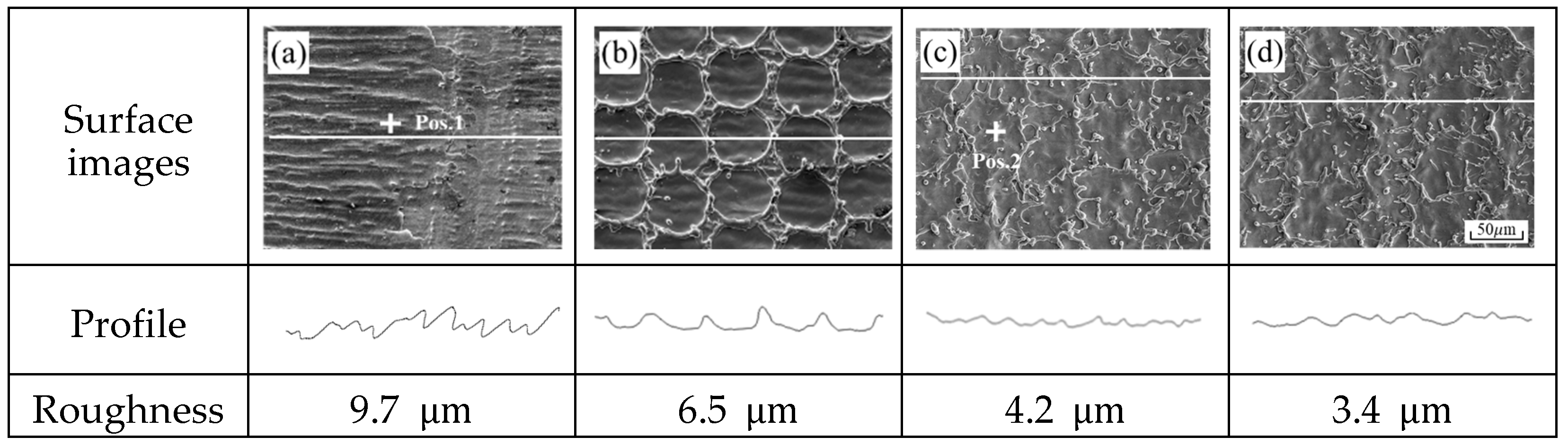
Figure 4 illustrates the enlarged SEM image, profile, and roughness of the weld surface before and after laser cleaning in
Figure 3a–d. Before laser cleaning, a nonuniform oxide layer was observed on the surface of the weldment. After laser cleaning, traces of the irradiated circular laser beam were observed on the specimen. As energy density increased, the thermal effects of laser energy also increased. Accordingly, both the spot size irradiated on the material, and the influence of laser energy on the behaviors of molten metal increased. Therefore, under the condition of the energy density of 3 J/cm
2, the size of laser beams irradiated on the specimen became smaller than 97 μm, leading to an absence of overlapped laser beams. However, when the energy density was increased to 5 J/cm
2 or more, there was a 50% overlap between the laser beams, enabling uniform cleaning. The surface roughness of the specimen was the highest at approximately 9.7 μm before laser cleaning. The nonuniform oxidized layer was removed after laser irradiation, and the roughness of the surface decreased. Under the condition of the energy density of 3 J/cm
2, the surface profile with the shape of a crater was observed. When energy density was 5 J/cm
2 or more, the surface roughness slightly decreased because of the overlapped laser beams.
Figure 5 illustrates the EDS spot analysis results at position 1 and 2 illustrated in
Figure 4. Before laser cleaning, components of oxides, such as SiO
2 and iron oxides, were detected in the specimen. After laser cleaning, these oxide components were removed. Subsequently, components of stainless steel, which was the base metal, were detected. These results verify that oxides on the surface of the specimen were completely removed without thermal damage caused by laser heat sources under the condition of energy density ranging from 5 to 7 J/cm
2. In addition, overlapping of laser beams formed a roughness of approximately under 5 μm on the surface of the specimen.
3.1.2. Effects of Defocused Distance
When laser cleaning is applied to a gas fuel supply pipe, a defocus of the laser beam occurs because of the curvature of the pipe. Provided laser cleaning of the prototype is manually performed, it is significantly important to identify a range of defocused distance, which can derive a similar quality of the laser cleaned prototype in the defocused distance to that in the focal position. The laser cleaning experiment according to the defocus distance was performed while changing the defocus distance from −10 mm to +10 mm at 2 mm intervals. At this time, energy density was fixed as 5 J/cm
2.
Figure 6 illustrates the surface of the laser cleaned specimen according to the defocused distance. As illustrated, the influence of the defocused distance is symmetrical to its increase in both positive and negative directions. In the focal position, contaminants, which remained on the surface of the specimen, were completely cleaned. On the other hand, as the focal position increases to + or −, the removal force of the contaminants decreases, and it can be seen that there is no significant difference compared to the specimen before laser cleaning.
A precise surface analysis on the specimen under the condition of the defocused distance ranging from 0 to +7 mm was conducted to identify the threshold of defocused distance for laser cleaning.
Figure 7 illustrates the morphology of the weld surface before and after laser cleaning according to the defocused distance. In the focal position, the surface of the weldment was cleaned uniformly and clearly because of the overlapping of laser beams. Such morphology of the surface was similarly observed under the condition of the defocused distance ranging from +1 to +2 mm. However, when the defocused distance was +3 to +5 mm, the size of laser beams irradiated on the material decreased as well as the laser beam overlap. Moreover, as laser beam patterns were distorted, the influence of laser heat sources on the material decreased gradually. However, the surface of the base metal was all scanned with the laser beam. When the defocused distance was + 6 mm or higher, no trace of the laser beam irradiation can be observed on the surface of the base metal. In other words, since the laser energy did not reach the laser cleaning threshold energy, we could not obtain the desired cleaning result. Therefore, the range of conditions for cleaning work was derived from a defocus distance of −5 mm to +5 mm.
The depth of focus (D.O.F.) can be calculated based on Equation (2) [
19].
Here, f is the focal length of a lens, λ is the wave length, D is the input beam diameter and M2 is a constant that evaluates the quality of the laser beam. The depth of focus is theoretically calculated as 6.9 mm. Such a value is lower than 10 mm, which is equal to the depth of focus obtained in experiments. Thus, it was determined that laser cleaning for eliminating oxide layer formed on the weld surface was successfully conducted, although the depth of focus was different from its theoretical value to a certain extent.
3.2. Effects of Laser Cleaning Applied to the Fillet Weldment
The angle of a portable optical head can be adjusted to perform laser cleaning of a fillet weldment uniformly. In this regard, this study conducted an experiment on analyzing the fillet weldment specimen according to different head angles to increase the applicability of the laser cleaning technology based on the shapes of a weldment.
Figure 8 illustrates the experimental method. The angle of the laser head was adjusted from 35° to 55° at intervals of 5°, and laser irradiation conditions included the average power of 100 W, the energy density of 5 J/cm
2, a laser beam overlap rate of 50%, and the focal position.
Figure 9 illustrates the experimental results of laser cleaning according to different laser head angles. It was determined that the remaining contaminants on the surface of the fillet weld, such as an oxidized layer, were completely removed under the entire conditions. Moreover, the influence of laser head angles was insignificant in the process of laser cleaning of the fillet weldment. This result was obtained because laser beams irradiated on each area belonged to the range of depth of focus when the corner of the specimen was laser cleaned.
These results verify the applicability of laser cleaning to butt and fillet weldments, which were shaped similarly as those of prototypes. In addition, the range of conditions of process parameters for facilitating laser cleaning was identified by a fundamental experiment according to butt and fillet welds.
3.3. Application of Laser Cleaning to the Prototype
Figure 10 shows the cleaning process method of a prototype using a portable laser cleaning equipment. The prototype was placed on the stage, and the operator laser cleaned welds of the prototype while moving the portable laser head. As for laser irradiation conditions, energy density and a laser beam overlap rate were fixed as 5 J/cm
2 and 50%, respectively. A defocused distance and laser head angle were controlled in the ranges of these conditions for facilitating laser cleaning, which were identified in the fundamental experiments. The experimental result indicated that the laser cleaning.
Technology facilitated significantly convenient cleaning of curved surfaces and 3D shapes, based on its advantage as a noncontact cleaning method.
Figure 11 illustrates surface images of prototypes, which were obtained before cleaning, after chemical cleaning, and after laser cleaning, respectively. Chemical cleaning of the prototype was conducted using the RA-885 chemical at room temperature, and two to five hours were required for processing. Before cleaning, the weld surface indicated that it was rough and non-uniform due to the remaining products of welding fume on it, which were caused by evaporated particles of alloying elements and oxidation. However, after chemical cleaning, contaminants formed on the weldment surface of the prototype was completely eliminated. In addition, the chemical cleaning process made the surface of the weldment smooth. The roughness of the chemical cleaned surface is about 1.2 μm. As for the laser cleaned prototype, contaminants on the surface of its weldment was completely eliminated as well. The enlarged image of the surface indicates traces of laser beams irradiated. At this time, as can be seen from
Figure 4, it can be seen that the roughness of the laser cleaned surface is about 5 μm. Moreover, a component analysis based on X-ray.
Diffraction was conducted to identify a state of oxide removal formed on the weldment of the prototype.
Figure 12 illustrates the XRD analysis results of prototype before and after cleaning. Before laser cleaning, iron oxides and main components of the base metal, Fe, were detected simultaneously. However, when chemical or laser cleaning was conducted, iron oxides were completely removed in the prototypes. Under such conditions, only the components of the base metal were detected.
The result of applying laser cleaning to the prototype indicated that the laser cleaning technology cleaned the surface of the prototype at a satisfactory level, without resulting in a toxic work environment and environmental pollution issues, which can be caused by chemical solvents utilized for chemical cleaning. In addition, the roughness of approximately 5 μm was formed on the surface of the weldment after laser cleaning. Based on this result, it is expected that a weldment, which was laser cleaned, can exhibit greater adhesive force of paint for anticorrosion of the product than a smooth weldment that was chemically cleaned [
20,
21].
4. Conclusions
This study analyzed the effects of weldment shapes and process parameters on the properties of laser cleaning applied to the weld surface of gas fuel supply pipe for DF engine. Based on the analytic results, it conducted experiments on applying laser cleaning to prototype. The experimental results of this study are as follows.
(1) As energy density increased, the thermal effects of laser energy on the material also increased. Accordingly, both the spot size irradiated on the material, and the influence of laser energy on the behaviors of molten metal on the metal surface increased. Consequently, oxides on the surface of the specimen were completely eliminated without thermal damage caused by laser heat sources under the condition of energy densities ranging from 5 to 7 J/cm2. In addition, the result of analyzing roughness indicated that under 5 μm roughness was formed on the surface of the laser cleaned weldment.
(2) Laser cleaning could perform at a defocused distance ranging from –5 to +5 mm, owing to the characteristics of the depth of focus. The experimental value of the depth of focus was higher than the theoretically calculated value, 6.9 mm. Nevertheless, it was verified that laser cleaning for eliminating oxides formed on the surface of a weldment can be successfully conducted. As a result, the best cleaning results can be obtained with an energy density of 5 J/cm2 and a focal position.
(3) The experimental results verified the applicability of laser cleaning to both butt and fillet weldments, which were shaped in a similar way as those of prototypes. In addition, satisfactory laser cleaning results were obtained despite a change in the angle of a laser head.
(4) Results showed that the laser cleaning technology could clean the surface of the prototype at a satisfactory level without resulting in a toxic work environment and environmental pollution issues. Since the roughness of about 5 μm is formed on the weldment surface after laser cleaning, it is expected that a weldment that was laser cleaned can exhibit greater adhesive force of paint for anticorrosion of the product than a smooth weldment that was chemically cleaned.
Author Contributions
Conceptualization, J.-D.K. and J.-E.K.; Methodology, J.-D.K. and J.-E.K.; Validation, J.-D.K. and J.-E.K.; Investigation, J.-E.K., J.-M.L., H.-S.C.; Resources, P.-S.K., J.-M.L., H.-S.C.; Writing—Original Draft Preparation, J.-E.K.; Writing—Review and Editing, J.-D.K.; Visualization, J.-E.K.; Supervision, J.-D.K.; Project Administration, J.-D.K.; Funding Acquisition, J.-D.K. All authors have read and agreed to the published version of the manuscript.
Funding
This research received no external funding.
Institutional Review Board Statement
Not applicable.
Informed Consent Statement
Not applicable.
Data Availability Statement
Not applicable.
Acknowledgments
Followings are results of a study on the “Leaders in INdustry-university Cooperation +” Project, supported by the Ministry of Education and National Research Foundation of Korea. This work was supported by the Korea Institute for Advancement of Technology (KIAT) grant funded by the Korea Government (MOTIE) (P0008763, The Competency Development Program for Industry Specialist). This paper is a revised and expanded version of a paper entitled ‘A study on the application of laser cleaning on the weld of the gas supply pipe for DF engine’ presented at the International Symposium on Marine Engineering and Technology 2021.
Conflicts of Interest
The authors declare no conflict of interest.
References
- IMO Marine Environment Protection Committee, 72nd Session. Available online: http://www.imo.org (accessed on 20 April 2018).
- Ryu, B.R.; Anh, D.P.; Lee, Y.H.; Kang, H.K. Study on LNG cold energy recovery using combined refrigeration and ORC system: LNG-fueled refrigerated cargo carriers. J. Korean Soc. Mar. Eng. 2021, 45, 70–78. [Google Scholar] [CrossRef]
- Yao, S.; Shen, X.; Luo, J. Design and optimization of LNG cold energy utilization scheme for dual fuel main engine of 37000DWT asphalt ship. Int. J. Green Energy 2021, 18, 1289–1301. [Google Scholar] [CrossRef]
- Tian, Z.; Yue, Y.; Zhang, Y.; Gu, B.; Gao, W. Multi-Objective Thermo-Economic Optimization of a Combined Organic Rankine Cycle (ORC) System Based on Waste Heat of Dual Fuel Marine Engine and LNG Cold Energy Recovery. Energies 2020, 13, 1397. [Google Scholar] [CrossRef] [Green Version]
- Oliveira, J.; Shen, J.; Zeng, Z.; Park, J.M.; Choi, Y.T.; Schell, N.; Maawad, E.; Zhou, N.; Kim, H.S. Dissimilar laser welding of a CoCrFeMnNi high entropy alloy to 316 stainless steel. Scr. Mater. 2022, 206, 114219. [Google Scholar] [CrossRef]
- Oliveira, J.; Shen, J.; Escobar, J.; Salvador, C.; Schell, N.; Zhou, N.; Benafan, O. Laser welding of H-phase strengthened Ni-rich NiTi-20Zr high temperature shape memory alloy. Mater. Des. 2021, 202, 109533. [Google Scholar] [CrossRef]
- Ke, W.; Bu, X.; Oliveira, J.; Xu, W.; Wang, Z.; Zeng, Z. Modeling and numerical study of keyhole-induced porosity formation in laser beam oscillating welding of 5A06 aluminum alloy. Opt. Laser Technol. 2021, 133, 106540. [Google Scholar] [CrossRef]
- Razaba, M.K.A.A.; Noorb, A.M.; Jaafarc, M.S.; Abdullahb, N.H.; Suhaimid, F.M.; Mohamedb, M.; Adame, N.; Yusuf, N.A.A.N. A review of incorporating Nd: YAG laser cleaning principal in automotive industry. J. Radiat. Res. Appl. Sci. 2018, 11, 393–402. [Google Scholar] [CrossRef] [Green Version]
- Li, Z.; Zhang, D.; Su, X.; Yang, S.; Xu, J.; Ma, R.; Shan, D.; Guo, B. Removal mechanism of surface cleaning on TA15 titanium alloy using nanosecond pulsed laser. Opt. Laser Technol. 2021, 139, 106998. [Google Scholar] [CrossRef]
- Zhang, G.; Hua, X.; Huang, Y.; Zhang, Y.; Li, F.; Shen, C.; Cheng, J. Investigation on mechanism of oxide removal and plasma behavior during laser cleaning on aluminum alloy. Appl. Surf. Sci. 2020, 506, 144666. [Google Scholar] [CrossRef]
- Shamsujjoha, M.; Agnew, S.R.; Melia, M.A.; Brooks, J.R.; Tyler, T.J.; Fitz-Gerald, J.M. Effects of laser ablation coating removal (LACR) on a steel substrate: Part 1. Surface profile, microstructure, hardness, and adhesion. Surf. Coat. Technol. 2015, 281, 193–205. [Google Scholar] [CrossRef]
- Wei, P.; Chen, Z.; Wang, D.; Zhang, R.; Li, X.; Zhang, F.; Sun, K.; Lei, Y. Effect of laser cleaning on mechanical properties of laser lap welded joint of SUS310S stainless steel and 6061 aluminum alloy. Mater. Lett. 2021, 291, 129549. [Google Scholar] [CrossRef]
- Zhou, C.; Li, H.; Chen, G.; Wang, G.; Shan, Z. Effect of single pulsed picosecond and 100 nanosecond laser cleaning on surface morphology and welding quality of aluminium alloy. Opt. Laser Technol. 2020, 127, 106197. [Google Scholar] [CrossRef]
- AlShaer, A.W.; Mistry, L.L.A. The effects of short pulse laser surface cleaning on porosity formation and reduction in laser welding of aluminium alloy for automotive component manufacture. Opt. Laser Technol. 2014, 54, 162–171. [Google Scholar] [CrossRef]
- Zhu, L.; Sun, B.; Li, Z.; Pan, X.; Chen, Y.; Cao, Y. The weld quality improvement via laser cleaning pre-treatment for laser butt welding of the HSLA steel plates. Weld. World 2020, 64, 1715–1723. [Google Scholar] [CrossRef]
- Kim, J.E.; Kim, P.S.; Lee, J.M.; Choe, H.S.; Kim, J.D. A study on the application of laser cleaning on the weld of the gas supply pipe for DF engine. In Proceedings of the International Symposium on Marine Engineering and Technology, Busan, Korea, 21–22 October 2021. [Google Scholar]
- Taheri, M.; Razavi, M.; Kashani-Bozorg, S.F.; Torkamany, M.J. Relationship between solidification and liquationcracks in the joining of GTD-111 nickel-basedsuperalloy by Nd:YAG pulsed-laser welding. J. Mater. Res. Technol. 2021, 15, 5635–5649. [Google Scholar] [CrossRef]
- Taheri, M.; Halvaee, A.; Kashani-Bozorg, S.F. Effect of Nd: YAG pulsed-laser welding parameters on microstructure and mechanical properties of GTD-111 superalloy joint. Mater. Res. Express 2019, 6, 07549. [Google Scholar] [CrossRef]
- Luxon, J.T.; Parker, D.E. Higher-order CO2 laser beam spot size and depth of focus determined. Appl. Opt. 1981, 20, 1933–1935. [Google Scholar] [CrossRef] [PubMed]
- See, T.L.; Liu, Z.; Cheetham, S.; Dilworth, S.; Li, L. Laser abrading of carbon fibre reinforced composite for improving paint adhesion. Appl. Phys. A 2014, 117, 1045–1054. [Google Scholar] [CrossRef]
- Kim, J.E.; Song, M.K.; Han, M.S.; Kim, J.D. A study on the application of laser cleaning process in shipbuilding industries using 100 W fiber laser. J. Mech. Sci. Technol. 2021, 35, 1421–1427. [Google Scholar] [CrossRef]
Figure 1.
Experimental equipment and setup for laser cleaning.
Figure 1.
Experimental equipment and setup for laser cleaning.
Figure 2.
Laser cleaning experimental method according to the shape of the weld; (a) Butt weld, (b) Fillet weld.
Figure 2.
Laser cleaning experimental method according to the shape of the weld; (a) Butt weld, (b) Fillet weld.
Figure 3.
Photos of the laser cleaned surface according to energy density; (a) Before laser cleaning, (b) 3 J/cm2, (c) 5 J/cm2, (d) 7 J/cm2, (e) 9 J/cm2.
Figure 3.
Photos of the laser cleaned surface according to energy density; (a) Before laser cleaning, (b) 3 J/cm2, (c) 5 J/cm2, (d) 7 J/cm2, (e) 9 J/cm2.
Figure 4.
SEM images, profile and roughness of the surface before and after laser cleaning according to energy density and 1 and 2 positions of EDS spot analysis; (a) Before laser cleaning, (b) 3 J/cm2, (c) 5 J/cm2, (d) 7 J/cm2.
Figure 4.
SEM images, profile and roughness of the surface before and after laser cleaning according to energy density and 1 and 2 positions of EDS spot analysis; (a) Before laser cleaning, (b) 3 J/cm2, (c) 5 J/cm2, (d) 7 J/cm2.
Figure 5.
EDS spot analysis results at positions 1 and 2 shown in
Figure 4; (
a) Pos. 1, (
b) Pos. 2.
Figure 5.
EDS spot analysis results at positions 1 and 2 shown in
Figure 4; (
a) Pos. 1, (
b) Pos. 2.
Figure 6.
Photos of the laser cleaned surface according to defocus distance.
Figure 6.
Photos of the laser cleaned surface according to defocus distance.
Figure 7.
Morphology of the weld surface before and after laser cleaning according to defocus distance; (a) Un-cleaned, (b) fd = 0 mm, (c) fd = +1 mm, (d) fd = +2 mm, (e) fd = +3 mm, (f) fd = +4 mm, (g) fd = +5 mm, (h) fd = +6 mm, (i) fd = +7 mm.
Figure 7.
Morphology of the weld surface before and after laser cleaning according to defocus distance; (a) Un-cleaned, (b) fd = 0 mm, (c) fd = +1 mm, (d) fd = +2 mm, (e) fd = +3 mm, (f) fd = +4 mm, (g) fd = +5 mm, (h) fd = +6 mm, (i) fd = +7 mm.
Figure 8.
Schematic of fillet weld laser cleaning experiment method according to laser head tilt angle.
Figure 8.
Schematic of fillet weld laser cleaning experiment method according to laser head tilt angle.
Figure 9.
Photos of the laser cleaned surface according to laser head tilt angle of the fillet weld; (a) Un-cleaned, (b) 35°, (c) 40°, (d) 45°, (e) 50°, (f) 55°.
Figure 9.
Photos of the laser cleaned surface according to laser head tilt angle of the fillet weld; (a) Un-cleaned, (b) 35°, (c) 40°, (d) 45°, (e) 50°, (f) 55°.
Figure 10.
Laser cleaning application of gas fuel supply pipe prototype.
Figure 10.
Laser cleaning application of gas fuel supply pipe prototype.
Figure 11.
Surface images of prototypes before and after cleaning; (a) Before cleaning, (b) Chemical cleaning, (c) Laser cleaning.
Figure 11.
Surface images of prototypes before and after cleaning; (a) Before cleaning, (b) Chemical cleaning, (c) Laser cleaning.
Figure 12.
XRD analysis results of prototype before and after cleaning.
Figure 12.
XRD analysis results of prototype before and after cleaning.
Table 1.
Chemical compositions of STS316L.
Table 1.
Chemical compositions of STS316L.
| Element | C | Si | Mn | P | S | Cr | Ni | Mo | Fe |
|---|
| Wt.% | 0.02 | 0.572 | 1.089 | 0.03 | 0.003 | 16.213 | 10.120 | 2.077 | Bal. |
Table 2.
Specification of laser cleaning equipment.
Table 2.
Specification of laser cleaning equipment.
| Q-Switching Fiber Laser | Value |
|---|
| Beam mode | Single mode |
| Input beam diameter (D) | 7 mm |
| Focal length (f) | 250 mm |
| ) | 1064 nm |
| Average power (Pave) | 100 W |
| Peak power (Pp) | 6.7 kW |
| ) | 150 ns |
| Beam size | |
| M2 | 2 |
| Publisher’s Note: MDPI stays neutral with regard to jurisdictional claims in published maps and institutional affiliations. |
© 2021 by the authors. Licensee MDPI, Basel, Switzerland. This article is an open access article distributed under the terms and conditions of the Creative Commons Attribution (CC BY) license (https://creativecommons.org/licenses/by/4.0/).


