Article

Performance Analysis of Direct Torque Controllers in Five-Phase Electrical Drives

1
Department of Electrical Engineering, University of Seville, 41092 Seville, Spain
2
Department of Electronic Engineering, University of Seville, 41092 Seville, Spain
*
Author to whom correspondence should be addressed.
Appl. Sci. 2021, 11(24), 11964; https://doi.org/10.3390/app112411964
Submission received: 18 November 2021 / Revised: 3 December 2021 / Accepted: 7 December 2021 / Published: 16 December 2021
(This article belongs to the Special Issue Electric Power Applications)

Abstract

:
The industrial application of electric machines has grown in the last decades, thanks to the development of microprocessors and power converters, which have permitted their use as variable-speed drives. Although three-phase machines are the common trend, the interest of the research community has recently focused on machines with more than three phases, known as multiphase machines. The principal reason lies in the exploitation of their advantages in terms of reliability, i.e., post-fault operating capability. Additionally, multiphase machines provide a better current distribution among phases, and lower current harmonic production in the power converter, than conventional three-phase machines. However, multiphase drive applications require the development of complex controllers to regulate the torque (or speed) and flux of the machine. In this regard, direct torque controllers have appeared as a viable alternative due to their easy formulation and high flexibility to incorporate control objectives. However, these controllers face some peculiarities and limitations in their use that require attention. This work aims to tackle direct torque control as a viable alternative for the regulation of multiphase drives. Special attention will be paid to the development of the control technique and the expected benefits and limitations in the obtained results. Case examples based on symmetrical five-phase induction machines with distributed windings in the motoring mode of operation will be used to this end.

1. Introduction

It is expected that about 80% of all the produced energy will be used by electric drives by 2030, playing a major role in the automotive field, where they will dominate almost 50% of the market by that year. Furthermore, electric drives are the basis of locomotive traction, electric ship propulsion, electric aircraft with various auxiliary functions (e.g., fuel pumps, starter/generator solutions, etc.), and renewable energy production. Although conventional three-phase drives represent the principal choice for industrial applications, multiphase ones have recently aroused the interest of practitioner engineers and researchers in the field. Any energy conversion system formed by a multiphase electric machine and converter and regulated by a certain control technique is called a multiphase drive. The first application of such a system, particularly for a five-phase drive, was used in the late 1960s [1], showing the advantages of multiphase systems over conventional three-phase ones. The main interest in the proposal was that the higher number of phases yields a torque ripple three times lower with respect to the equivalent three-phase case due to a better power distribution per phase, this being one of the most reported problems in conventional drives at that time. However, it was not until the end of the 20th and the beginning of the 21st centuries that the interest of researchers in multiphase machines was renewed due to two main reasons. First, the development of high-power and high-frequency semiconductors and, consequently, the appearance of pulse width modulation (PWM) methods to control the ON and OFF states of these electronic devices, as well as the energy conversion process. Second, there is the development of microelectronic technology and the appearance of powerful electronic devices with the ability to implement control algorithms in real time, such as digital signal processors (DSPs) and field-programmable gate arrays (FPGAs).
Notwithstanding the above, the crucial reason for the renewed interest in multiphase drives can be found in the intrinsic benefits that they provide versus the conventional three-phase ones. These benefits are based on the extra degrees of freedom introduced by the higher number of phases and are principally the following:
  • The fault-tolerant capability against a fault situation in the machine and/or the power converter, first presented in [2]. An n-phase machine can operate after one or several fault occurrences without any external equipment, as long as the number of healthy phases remains greater than or equal to three (assuming a single isolated neutral connection). Consequently, the system reliability is enhanced at the expense of a reduction in the post-fault electrical torque production.
  • The capability of increasing the power density in healthy operation by injecting specific current harmonics, exposed in [3]. This is possible in certain multiphase machine configurations based on concentrated windings, where the lower current harmonic components can be used to increase the torque production.
These advances and advantages underlie the adoption of multiphase drives in specific industry applications such as variable-speed drives [4,5]. Electric propulsion of ships, electric vehicle traction (hybrid/electric vehicles and locomotives), wind energy generation, and low-power electric systems for more electric aircrafts are fields where research has been focused in the last 20 years [6,7]. The interest of multiphase machines in the cited applications, instead of the conventional three-phase counterparts, arises from the high-torque/current production and/or more robust and cheaper fault-tolerant capability that are usually required. Benchmark solutions adopted by important companies are: the Hyundai ultra-high-speed elevator, based on a 1.1 MW nine-phase electric drive; the 5 MW 12-phase electric drives in the Gamesa wind turbines for onshore and offshore plants; and the 20 MW 15-phase electric drive for ship propulsion introduced by the GE Power Conversion company in the Royal Navy.
To create a body of knowledge, recent research works review advances in the field of multiphase drives including their industrial applications, machine design and modeling, types of converters, modulation techniques, and control strategies; and explore innovative uses of their degrees of freedom (i.e., multimotor drives, battery chargers, post-fault control, or dynamic breaking) [8,9,10,11]. Then, these state-of-the-art analyses in the multiphase drives’ topic set the advances in the area in the last decades. In general, they show that symmetrical five-phase and asymmetrical six-phase machines with isolated neutrals are the most popular multiphase machine types in the research community, while an evolution in the control techniques has been necessary in order to optimally exploit their inherent advantages. In this regard, asymmetric six-phase machines with isolated neutrals can be considered as two conventional three-phase machines coupled in a common case, while the five-phase drive can be considered the ideal case example to illustrate any study in the multiphase drive field.
Although field-oriented control (FOC) methods, based on decoupled control of the flux and electromagnetic torque and assisted by modulation stages, can be considered as the most popular control technique for conventional and multiphase drives [8,9], direct control techniques have recently been presented as interesting competitors [12,13,14]. The essence of direct controllers is to eliminate any form of modulation, forcing the states of the power switches to rapidly track a reference value. Then, the meaning of ‘direct control’ techniques is related to control strategies without the intervention of a pulse width modulation or any other form of modulation, providing control commands that are applied directly to the power converter. As a main consequence, direct controllers, being direct torque controllers (DTC) are the most extended industrial alternative, can favor fast torque responses and control robustness with respect to the variation of the electrical parameters of the machine. In this regard, DTC appears to be a viable (from a commercial perspective) control alternative in conventional three-phase drives due to an easy formulation and high flexibility to incorporate different control objectives. However, the use of DTC in multiphase drives is restricted in normal operation due to the impossibility of regulating more than two degrees of freedom (electrical torque and stator flux).
The objective of our work is to review the main concepts and interest of DTC controllers and to perform a performance analysis in multiphase drives, particularizing to the five-phase case. Different operating conditions, including normal operation and limited electrical/magnetic or faulty situations, are analyzed, where the DTC technique is effectively extended to face the operation of the five-phase induction machine. Experimental tests are provided to show that the speed, torque, and flux references are successfully tracked in all cases.

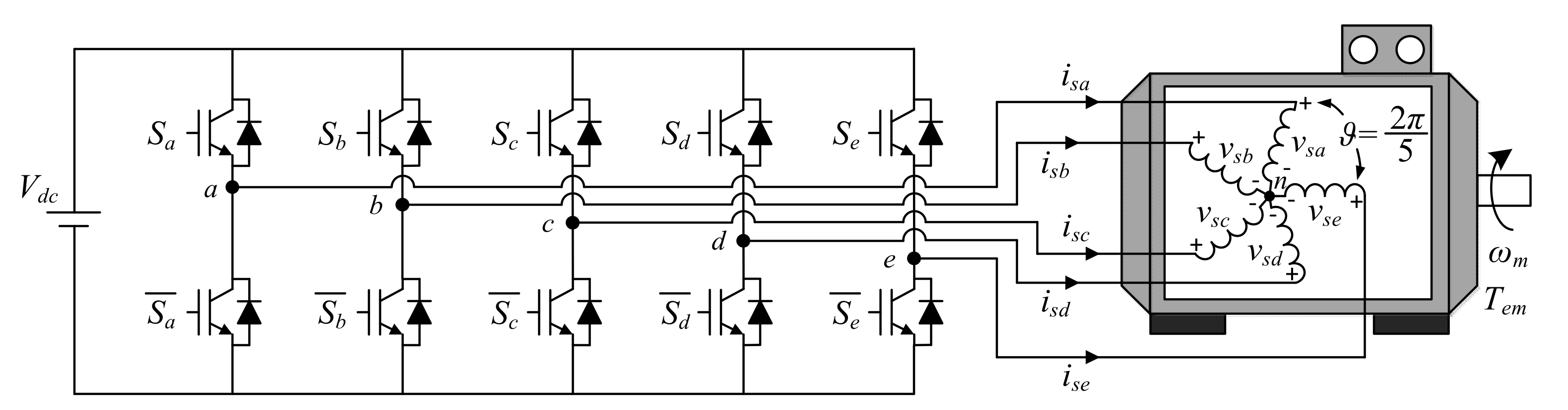
2. The Case Study: Five-Phase Distributed Windings Induction Motor Drive Using a Conventional Two-Level VSI

The system under study will be analytically examined in this section. It is based on a five-phase Induction Machine (IM) with a squirrel-cage rotor and symmetrically distributed stator windings (spatial equal displacement between windings) fed by a DC power supply through a five-phase two-level voltage source inverter (VSI). A graphical representation of the analyzed system is shown in Figure 1.
The five-phase two-level VSI has 25 = 32 different switching states characterized by the switching vector [Sa Sb Sc Sd Se]T, with Sk = {0,1}. Therefore, the phase voltages generated in the stator (subindex s), [vsa vsb vsc vsd vse]T, can be defined as a function of the switching states as follows:
v s a v s b v s c v s d v s e = V d c 5 4 1 1 1 1 1 4 1 1 1 1 1 4 1 1 1 1 1 4 1 1 1 1 1 4 S a S b S c S d S e
Note that the midpoint of the external DC power supply (Vdc) is assumed to be the ground of the electrical system and a balanced load is also considered, so the sum of all phase voltages must be equal to zero (vsa + vsb + vsc + vsd + vse = 0).
The machine is modeled in the stationary reference frame (a, b, c, d, e) with a set of voltage equilibrium equations obtained from the electromagnetic circuits of the stator and rotor (subindexes s and r, respectively), but then represented in two orthogonal planes, namely, αβ and xy, plus the homopolar component z as follows:
v s α v s β v s x v s y v s z = R s i s α i s β i s x i s y i s z + d d t λ s α λ s β λ s x λ s y λ s z
λ s α λ s β λ s x λ s y λ s z = L s 0 0 0 0 0 L s 0 0 0 0 0 L l s 0 0 0 0 0 L l s 0 0 0 0 0 L l s i s α i s β i s x i s y i s z + L m 0 0 0 0 0 L m 0 0 0 0 0 0 0 0 0 0 0 0 0 0 0 0 0 0 i r α i r β i r x i r y i r z
0 0 0 0 0 = R r i r α i r β i r x i r y i r z + d d t λ r α λ r β λ r x λ r y λ r z + 0 ω r 0 0 0 ω r 0 0 0 0 0 0 0 0 0 0 0 0 0 0 0 0 0 0 0 λ r α λ r β λ r x λ r y λ r z
λ r α λ r β λ r x λ r y λ r z = L r 0 0 0 0 0 L r 0 0 0 0 0 L l r 0 0 0 0 0 L l r 0 0 0 0 0 L l r i r α i r β i r x i r y i r z + L m 0 0 0 0 0 L m 0 0 0 0 0 0 0 0 0 0 0 0 0 0 0 0 0 0 i s α i s β i s x i s y i s z
where λ denotes flux variables, ωr is the electrical equivalent speed of the rotor, the resistances of the stator, and the rotor are Rs and Rr, respectively, the mutual inductance is represented by Lm, while Lls and Llr designate the leakage inductances of the stator and the rotor, respectively. Finally, Ls = Lls + Lm and Lr = Llr + Lm are called stator and rotor inductances. This is called the Clarke decoupled model of the electrical machine because a Clarke transformation (C5 shown below, with ϑ = 2π/5) is used to refer the rotor variables to the stator reference frame, leading to an invariant transformation of voltage and current magnitudes and allowing a considerable simplification of the machine model.
C 5 = 2 5 1 cos ϑ cos 2 ϑ cos 3 ϑ cos 4 ϑ 0 sin ϑ sin 2 ϑ sin 3 ϑ sin 4 ϑ 1 cos 2 ϑ cos 4 ϑ cos 6 ϑ cos 8 ϑ 0 sin 2 ϑ sin 4 ϑ sin 6 ϑ sin 8 ϑ 1 2 1 2 1 2 1 2 1 2
Note that the stator voltages applied to the electrical machine using the power converter must be referred to the same coordinates, which is easily done by multiplying C5 by voltages in the (a, b, c, d, e) reference frame. The same happens with the stator current and flux, as well as with the rotor magnitudes (voltage, current, and flux).
v s α v s β v s x v s y v s z = C 5 v s a v s b v s c v s d v s e
Applying this transformation, 30 active voltage vectors and 2 null vectors can be applied at the connection terminals of the electrical machine. Figure 2 shows the two-dimensional projections obtained for every vector, identified with the decimal number equivalent of their respective switching state [Sa Sb Sc Sd Se]T expressed in binary logic (1 or 0), being Sa and Se the most and the least significant bits, respectively. These vectors uniformly divide the space that they occupy in 10 sectors with a separation of π/5 between them. Likewise, active voltage vectors can be classified according to their magnitude in long (0.647 Vdc), medium (0.4 Vdc), and short (0.247 Vdc) vectors. The switching states that generate long vectors in the αβ plane correspond to those that generate short vectors in the plane xy and vice versa. The switching states corresponding to vectors of medium magnitude in the αβ plane, also generate medium vectors in the plane xy. Null vectors are generated by the same switching states in both planes. This transformation allows for a detailed study of the harmonic components, since they are projected in certain planes. In particular, the fundamental frequency together with the harmonics of order 10 k ± 1 (k = 0, 1, 2, etc.) are mapped in the αβ plane, while the harmonics of order 10 k ± 3 are related to the plane xy. The homopolar component and harmonics of order 5 k are projected on the z-axis.
In distributed winding induction machines, as the one used in our study, only the components of the αβ plane are involved in torque production and a new transformation of variables is desirable (see Figure 3), moving the αβ plane to a new rotating reference frame dq (at synchronous speed ωa), where the components are not oscillating, are constant in steady state and vary only in transient state. The basis of this transformation is the Ps5 and Pr5 operators,
P s 5 = cos θ a sin θ a 0 0 0 sin θ a cos θ a 0 0 0 0 0 1 0 0 0 0 0 1 0 0 0 0 0 1 P r 5 = cos δ sin δ 0 0 0 sin δ cos δ 0 0 0 0 0 1 0 0 0 0 0 1 0 0 0 0 0 1 θ a = 0 t ω a d t δ = θ a θ = 0 t ω a ω r d t = 0 t ω s l d t
Giving the following mathematical representation of the system:
v s d v s q v s x v s y v s z = R s i s d i s q i s x i s y i s z + d d t λ s d λ s q λ s x λ s y λ s z + 0 ω a 0 0 0 ω a 0 0 0 0 0 0 0 0 0 0 0 0 0 0 0 0 0 0 0 λ r d λ r q λ r x λ r y λ r z
0 0 0 0 0 = R r i r d i r q i r x i r y i r z + d d t λ r d λ r q λ r x λ r y λ r z + 0 ω s l 0 0 0 ω s l 0 0 0 0 0 0 0 0 0 0 0 0 0 0 0 0 0 0 0 λ r d λ r q λ r x λ r y λ r z
λ s d λ s q λ s x λ s y λ s z = L s 0 0 0 0 0 L s 0 0 0 0 0 L l s 0 0 0 0 0 L l s 0 0 0 0 0 L l s i s d i s q i s x i s y i s z + L m 0 0 0 0 0 L m 0 0 0 0 0 0 0 0 0 0 0 0 0 0 0 0 0 0 i r d i r q i r x i r y i r z
λ r d λ r q λ r x λ r y λ r z = L r 0 0 0 0 0 L r 0 0 0 0 0 L l r 0 0 0 0 0 L l r 0 0 0 0 0 L l r i r d i r q i r x i r y i r z + L m 0 0 0 0 0 L m 0 0 0 0 0 0 0 0 0 0 0 0 0 0 0 0 0 0 i s d i s q i s x i s y i s z
On the other hand, the generated electromagnetic torque (Tem) can be obtained in different reference frames using the following equations, where n = 5 and p is the pair of poles of the electrical machine,
T e m = p n 2 L m i r α i s β i r β i s α
T e m = p n 2 λ s α i s β λ s β i s α
T e m = p n 2 i r α λ r β i r β λ r α
T e m = p n 2 L m L r λ r α i s β λ r β i s α
T e m = p n 2 L m i r d i s q i r q i s d
T e m = p n 2 λ s d i s q λ s q i s d
T e m = p n 2 i r d λ r q i r q λ r d
T e m = p n 2 L m L r λ r d i s q λ r q i s d
It is in turn mechanically coupled to the load applied on the machine shaft, verifying the following differential equation:
J m d ω m d t = T e m T L B m ω m
With ωm, the mechanical speed of the rotor shaft (ωr = p·ωm); TL, the load torque applied to the machine; Jm, the rotational inertial constant; and Bm, the friction coefficient of the rotor load bearings.

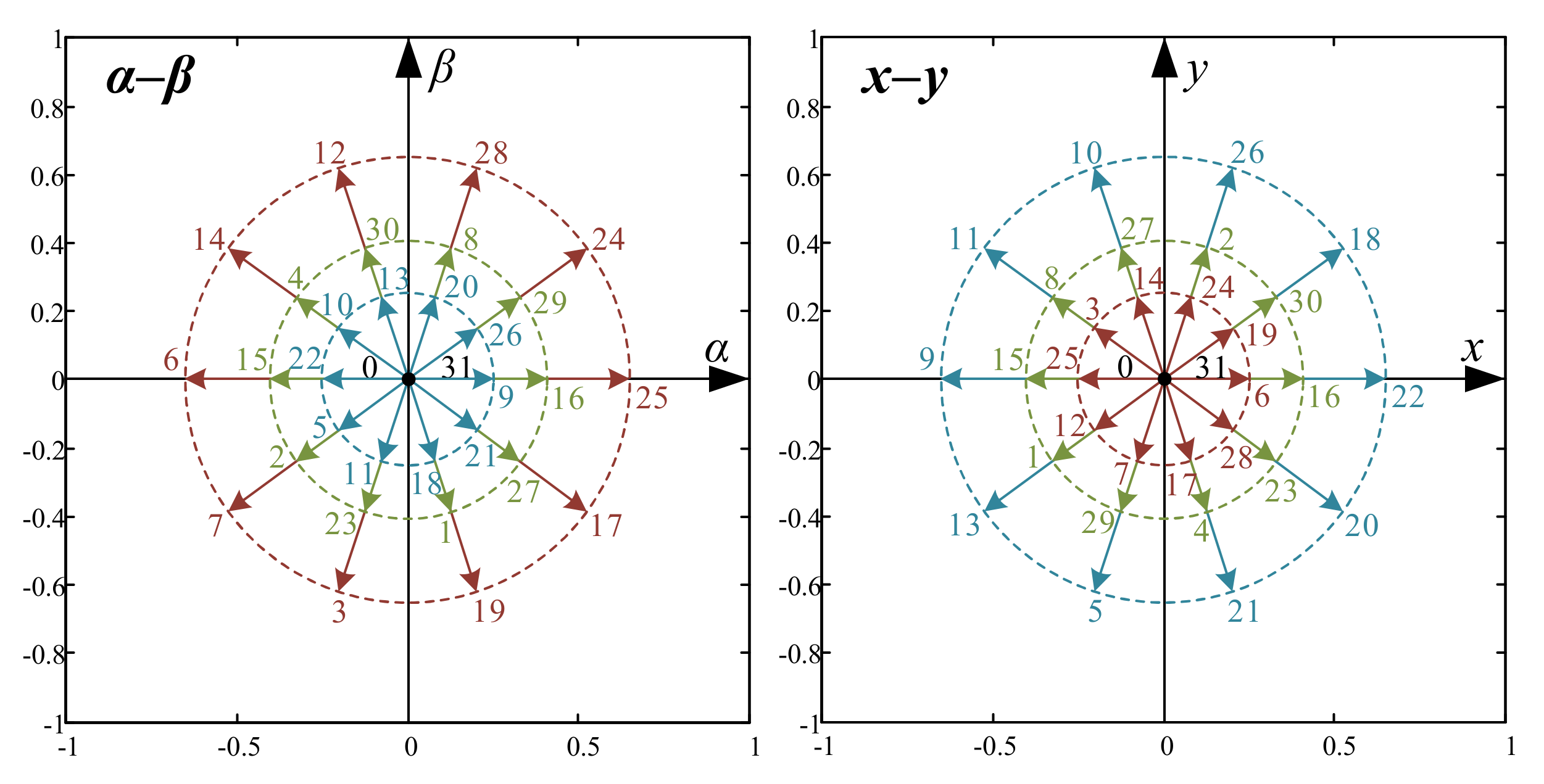
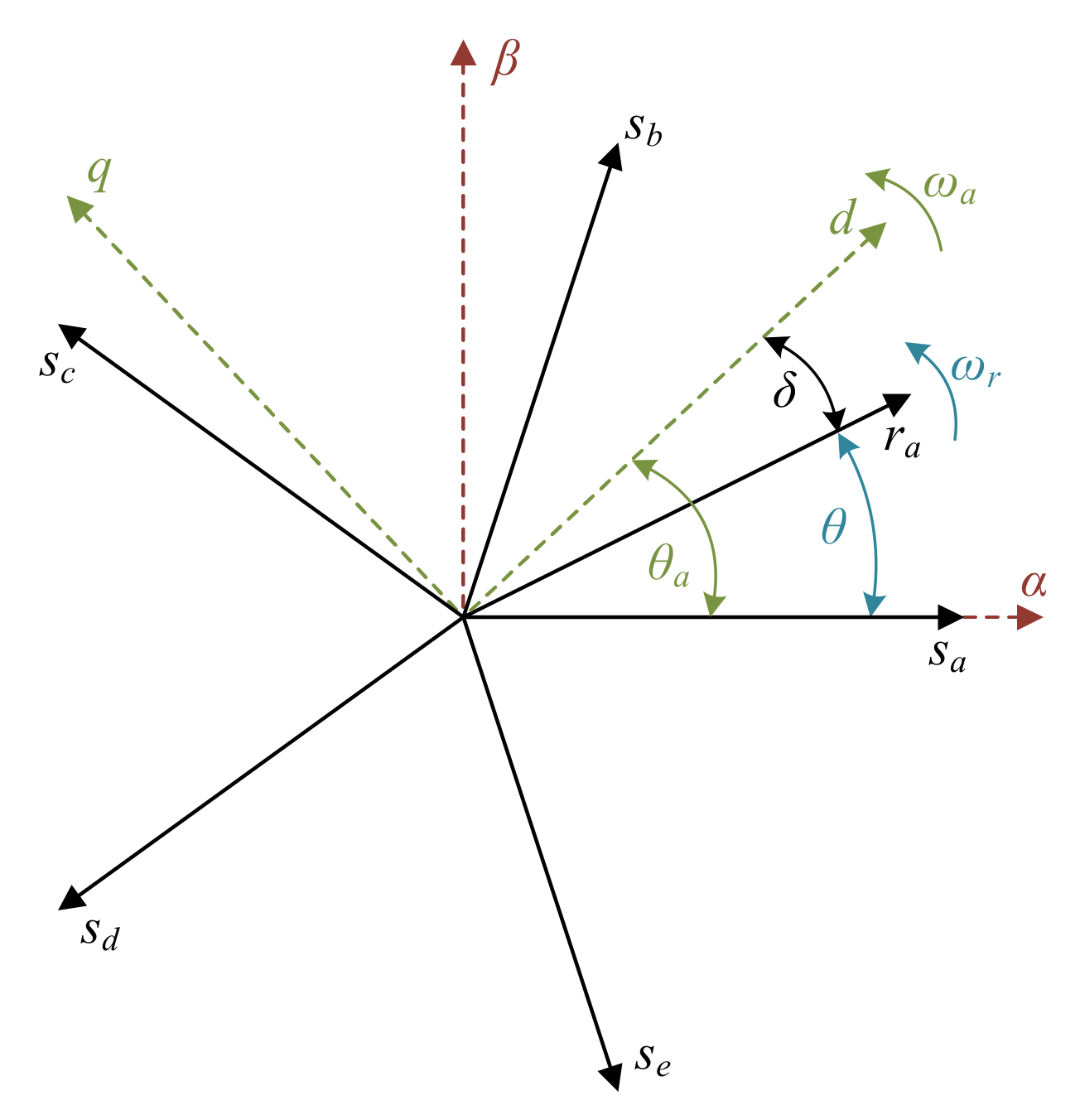
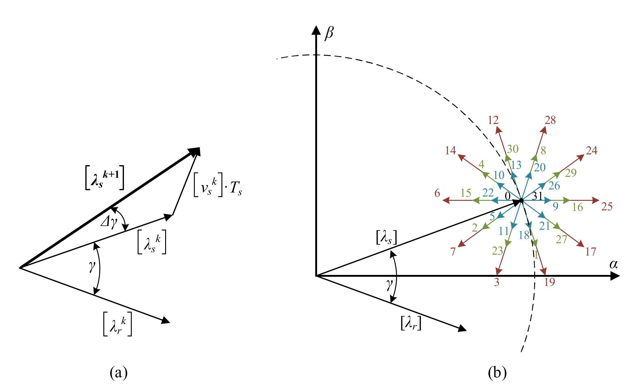
3. DTC in Five-Phase Drives

Direct Torque Control is a well-known strategy for three-phase electrical drives. It was presented in the mid-1980s by Takahashi [15] and Depenbrock [16], showing fast flux and torque responses, as well as more robustness with respect to the variation of the electrical parameters of the machine and generating a high-torque/flux ripple and harmonic current content, compared to the more standard field-oriented control technique. The operating principle is based on an off-line look-up table, which is used to select the stator voltage to be applied to the machine. The selection is made taking into account the position of the flux vector and the stator flux and electromagnetic torque error signals, obtained from the difference between reference and estimated values and processed using hysteresis comparators. Another disadvantage of DTC that should be considered from the analysis of its operating principle is that it does not generate a constant switching frequency. In fact, this switching frequency is variable and depends on the operating point and the bandwidth of the hysteresis controllers. Note, however, that DTC schemes have been proposed to also be used with PI regulators and space vector PWM methods (see [17]), to compensate for the variable switching frequency and reduce the torque and flux ripple.
DTC has been commercialized [18] and extended to the case of multiphase drives in recent times, considering different types of machines [19,20], machine neutral connections [21,22], and drives without speed sensors [23]. In the case of multiphase drives, since the controller has only two freedom degrees (stator flux and electromagnetic torque), there is no chance of regulating the current and voltage components in the orthogonal αβ and xy planes. In this sense, some DTC strategies have been developed that satisfy this additional requirement, controlling the current and voltage components in the αβ plane while reducing at the same time the current and voltage components in the xy plane. For example, in [24,25], a modification of the traditional control scheme is proposed, performing a two-step search to minimize the effect of low-order harmonics. Alternatively, the use of virtual vectors has been suggested to reduce current distortion [23]. Some criteria have also been included in the selection process within the look-up table to improve its performance in the low-speed region and an optimization between the two zero vectors to minimize the average switching frequency obtained [26]. On the other hand, and based on the virtual vectors defined in [23], different DTC schemes are presented defining new virtual vectors and avoiding the use of the zero vector to reduce the common-mode voltage generated by the VSI in [27,28], to improve open-phase fault operations in [29], or to avoid any reconfiguration of the controller when open-phase faults appear [30].
In our case example, the five-phase IM with distributed windings, the control goal is reduced to the αβ plane (torque and flux regulation), while the xy components are nullifying. The analysis is based on the machine model in the stationary reference frame, which defines the variation of the stator flux in the αβ subspace using a vector notation as:
Δ λ s α β = 0 t v s α β R s i s α β d t
If the voltage drop in the stator resistance is ignored for simplicity, it can be assumed that the variation in the modulus of the flux vector in a sampling period (Ts) depends on the voltage vector as follows:
Δ λ s α β v s α β T s
The electromagnetic torque behavior can be determined by the following expression:
T e m = 5 2 p k r σ L s λ r α β × λ s α β = 5 2 p k r σ L s λ r α β λ s α β sin γ σ = 1 L m 2 L s L r k r = L m L r
where γ is the angle of load (angle between the flux vectors of the stator and the rotor). Then, a change in γ, obtained by applying a voltage vector, produces an increase or decrease in Tem. Note that the rotor time constant is greater than the stator time constant, so it can be assumed that a slower variation of the rotor flux compared to the stator flux, and therefore the rotor flux, can be considered constant in a sampling time. Note also that there is an impact of a spatial voltage vector on the magnitude of the stator flux. Different results are obtained depending on the applied stator voltage (32 alternatives using the five-phases two-level VSI, being 30 active vectors and 2 null vectors; see Figure 4). In short, the applied voltage vector can be divided into a tangential and a radial component with respect to the flux. The tangential component produces a change in machine torque, increasing or decreasing the sine of the angle γ, while the radial component modifies the magnitude of the stator flux, increasing or decreasing its modulus. Hence, the flux and the electromagnetic torque are controlled simultaneously using DTC.
The application of the voltage vector controls the flux and electromagnetic torque and affects not only the αβ plane, but also the plane x–y, where losses and unwanted voltage and current harmonics are generated in the case study machine. Figure 2 and Figure 4 show that 32 voltage vectors with 4 different magnitudes can be applied: 2 null vectors (0 volts applied), 10 short vectors (0.247 Vdc volts applied), 10 medium vectors (0.4 Vdc volts applied), and 10 long vectors (0.647 Vdc volts applied). Note also (see Figure 2) that switching states that represent long vectors in the αβ plane, symbolize short vectors in the xy plane (and vice versa), while switching states that generate medium vectors in the αβ plane also cause medium vectors in the xy plane. In addition, long and medium voltage vectors with the same direction in the αβ subspace, are equivalent to medium and short vectors with opposite directions in the xy subspace. The same happens with medium and short vectors in the αβ plane, since they are equivalent to medium and long vectors with opposite directions in the plane xy. These geometrical characteristics make possible the definition of a kind of voltage vector, called virtual voltage vector or VVi [23], which minimizes currents in the xy plane. Each virtual vector is based on the application of two available voltage vectors (v1 and v2) during adequate dwell time ratios (Kv1 and Kv2) to generate zero average volts per second in the xy subspace. It is then possible to define in each sector a long virtual vector (formed by a long and a medium vector in the αβ plane) and a short virtual vector (formed by a medium and a short vector in the αβ plane), as shown in the following equations and in Figure 5 and Figure 6:
V V L i = v L o n g K v 1 + v M e d i u m K v 2
V V S i = v M e d i u m K v 1 + v S h o r t K v 2
For example, consider the long virtual vector in sector number one, formed by the voltage vectors 25 and 16 (v25 and v16, respectively), which are in the same direction in the αβ subspace and are opposite in the subspace xy. By selecting adequate values of Kv1 and Kv2, it is obtained zero average volts-per-second in the xy subspace (see Figure 5). Figure 6 shows all the virtual vectors in the αβ plane, VVLi being the long virtual vectors and VVSi the short ones. Furthermore, the dwell times of each vector in each sampling time Ts to achieve the minimization of the xy currents are Kv1 = 0.618 Ts and Kv2 = 0.382 Ts. However, it should be noted that even in the case where virtual voltage vectors are used, xy currents are controlled with an open-loop strategy. Consequently, the machine must have low asymmetries and spatial harmonic content and/or high impedance in the xy plane to effectively limit the circulation of xy currents. It is important to note that the xy components do not contribute to the torque in our case study machine, but they increase power losses in the electromechanical system. A good control practice is therefore to minimize the xy components.
The general implementation of the DTC technique, proposed in [31,32], can be done using the scheme shown in Figure 7, where flux and torque estimators are required (normal drives do not include flux and torque sensors, and their values must be estimated). The stator flux is regulated close to a reference value, using a two-level comparator with hysteresis band. Electromagnetic torque is controlled using a five-level comparator with a hysteresis band. Finally, a two-level comparator with a hysteresis band is applied to differentiate between low and normal speed operations of the drive (the effect of neglecting the voltage drop in the stator resistance cannot be neglected because it produces an appreciable drop in the stator flux vector when placed at the limit of some sectors [26]). To sum up, the estimated torque and flux values are used to compare with the reference values to select the applied stator voltage vector, using a correction term that depends on the speed operation and the following mathematical expressions:
λ s * > λ s α β d λ = + 1 λ s * λ s α β d λ = 1
T e m * T e m + Δ T e m 2 d T = + 2 T e m + Δ T e m 2 > T e m * > T e m + Δ T e m 4 d T = + 1 T e m + Δ T e m 4 T e m * T e m Δ T e m 4 d T = 0 T e m Δ T e m 4 < T e m * < T e m Δ T e m 2 d T = 1 T e m * T e m Δ T e m 2 d T = 2
ω m > ω m t h d ω = + 1 ω m ω m t h d ω = 1
With , dT, and the outputs of the flux, torque, and speed comparators, respectively, and ωmth the considered low-speed threshold. Selection of the applied VV is made using the lookup table shown in Table 1, as stated in [26,31,32].
Note that the flux and torque estimator considers the discrete-time state-space model of the machine to calculate the variables in the αβ plane through the following equation:
λ ^ s α λ ^ s β = σ L s 0 L m L r 0 0 σ L s 0 L m L r i s α i s β λ ^ r α λ ^ r β
λ ^ s = λ ^ s α β = λ ^ s α 2 + λ ^ s β 2
T ^ e m = p 5 2 λ ^ s α i s β λ ^ s β i s α
The look-up table of the DTC controller selects the appropriate virtual voltage vector in each sampling time according to the outputs of the hysteresis controllers and the sector where the stator flux is currently located, which is estimated as follows:
θ a = arctan λ ^ s β λ ^ s α
S e c t o r = 1 i f π 10 θ a π 10 2 i f π 10 θ a 3 π 10 3 i f 3 π 10 θ a 5 π 10 4 i f 5 π 10 θ a 7 π 10 5 i f 7 π 10 θ a 9 π 10 6 i f 9 π 10 θ a 11 π 10 7 i f 11 π 10 θ a 13 π 10 8 i f 13 π 10 θ a 15 π 10 9 i f 15 π 10 θ a 17 π 10 10 i f 17 π 10 θ a 19 π 10

4. Results and Discussion

To assess the performance of the DTC scheme, different experimental tests were performed on a conventional three-phase induction machine with 30 slots that was redesigned to have five phases and three pole pairs. The electrical and mechanical parameters of the multiphase electrical machine are depicted in Table 2. The reference stator flux (λs*) is set to its rating value (0.4 Wb) during the experiments, the applied sampling frequency is fixed to 10 kHz and the hysteresis bands of the torque and flux regulators are programmed to be 1% of the rating values (this value was experimentally obtained for our test rig using a trial and error method). The maximum reference torque is set to 3.25 N·m, according to machine limits. The multiphase power converter is based on two conventional three-phase VSIs from SEMIKRON® (two SKS-22F modules in which five power legs are used). The DC link voltage is set to 300 V using an external DC power supply. The electronic control unit is based on a MSK28335 board and a Texas Instruments® TMS320F28335 digital signal processor. A digital encoder (GHM510296R/2500) and the enhanced quadrature encoder pulse peripheral of the DSP are used to measure the rotor mechanical speed ωm. The load torque (TL), which is demanded in the tests, is set by an independently controlled DC machine that is mechanically coupled to the five-phase machine. The experimental test rig is shown in Figure 8, where some photographs of the real system are included.

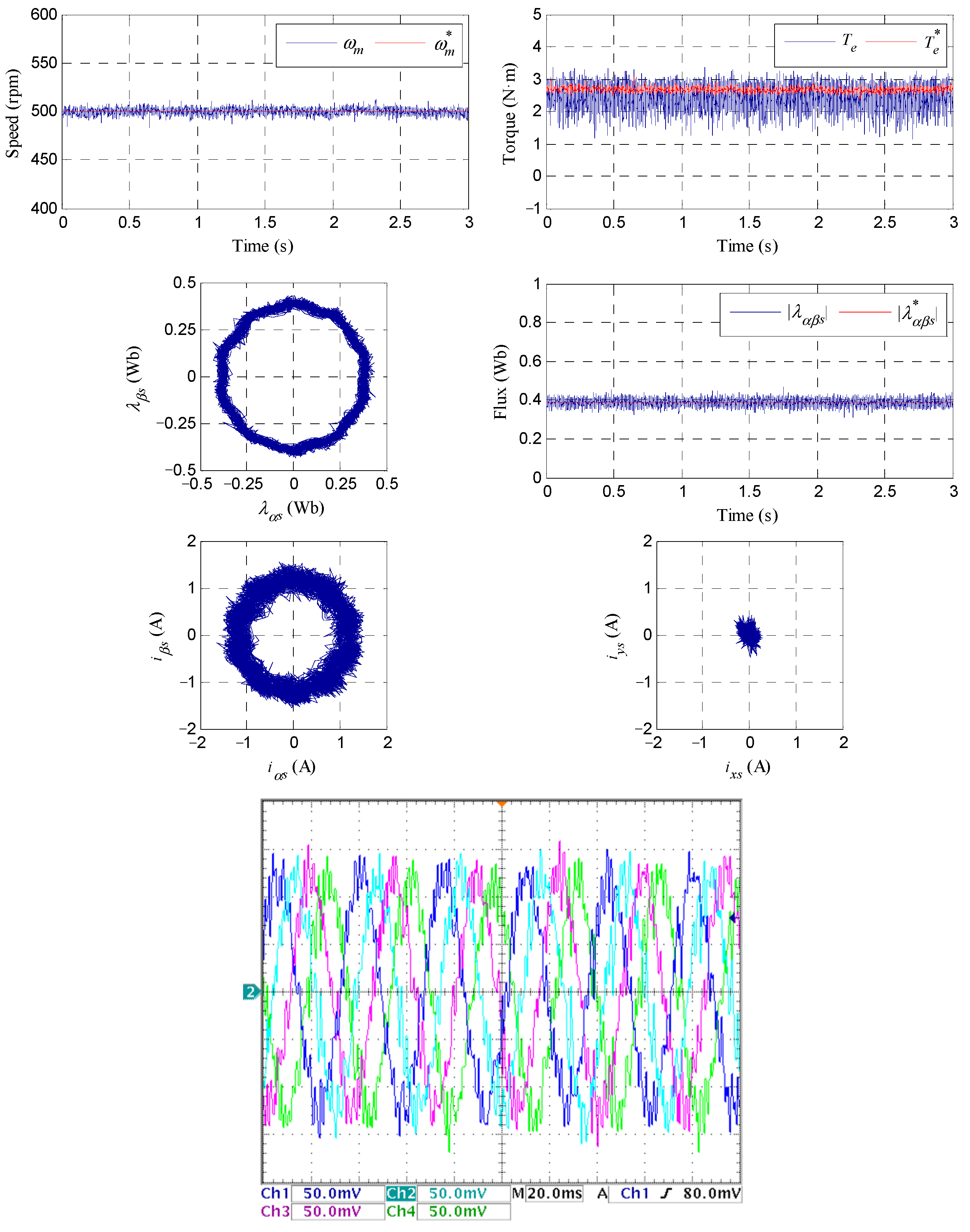
4.1. Steady-State Operation

First, the performance of the system in steady-state operation at 500 rpm is analyzed in Figure 9 and Figure 10, where different load torques are applied (1 N·m in Figure 9 and 2.75 N·m in Figure 10). The reference and measured values are colored red and blue, respectively. The speed and electrical torque responses are shown in the upper rows, where it is appreciated that the controller works well and the mechanical speed is successfully maintained in the reference value. Note that the electrical torque is mathematically estimated using the machine model, which produces some estimation errors. The reference and estimated stator flux in the regulated αβ plane are then shown in the second row, where it can be observed that the estimated stator flux values coincide with their references. Lastly, the measured stator currents are depicted in the last two rows, where it is appreciated that the αβ stator current vector describes a circular trajectory, with nearly null xy stator current components. Therefore, the control goals are met using the DTC controller in steady-state operation because the results obtained can be extended to different reference speed and load torques.

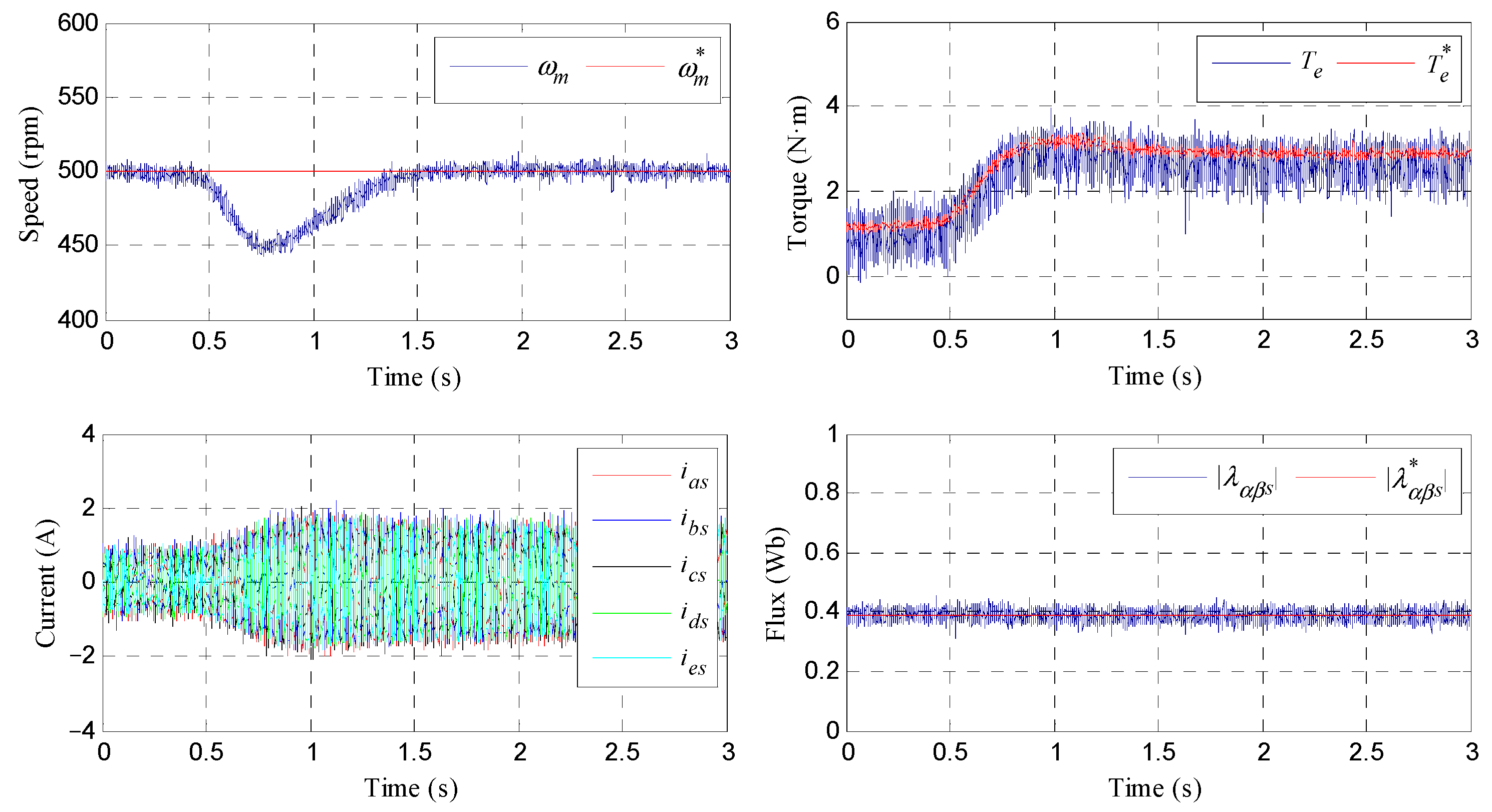
4.2. Load Torque Rejection

Then load torque rejection tests were performed. The results obtained are summarized in Figure 11, where the reference speed is 500 rpm and the coupled DC machine imposes a heavy load torque within the system limits at t = 0.5 s. A drop in the speed is observed when the load is suddenly applied; although, the controller successfully manages this disturbance, upper-left plot. The estimated electrical torque is also regulated to be the referred one in steady and transient states, as shown in the upper right figure, while stator phase currents increase to manage the increment in the load (see bottom-left timing diagram). The estimated stator flux value is regulated in steady and transient states to coincide with the references, as can be appreciated in the bottom right figure. Then, these results, which summarize the ones obtained under different operating conditions, prove a controlled electrical torque in the multiphase drive. Note that flat lines are also observed in the xy plane polar diagrams of the stator current, similar to the ones shown in Figure 9 and Figure 10.

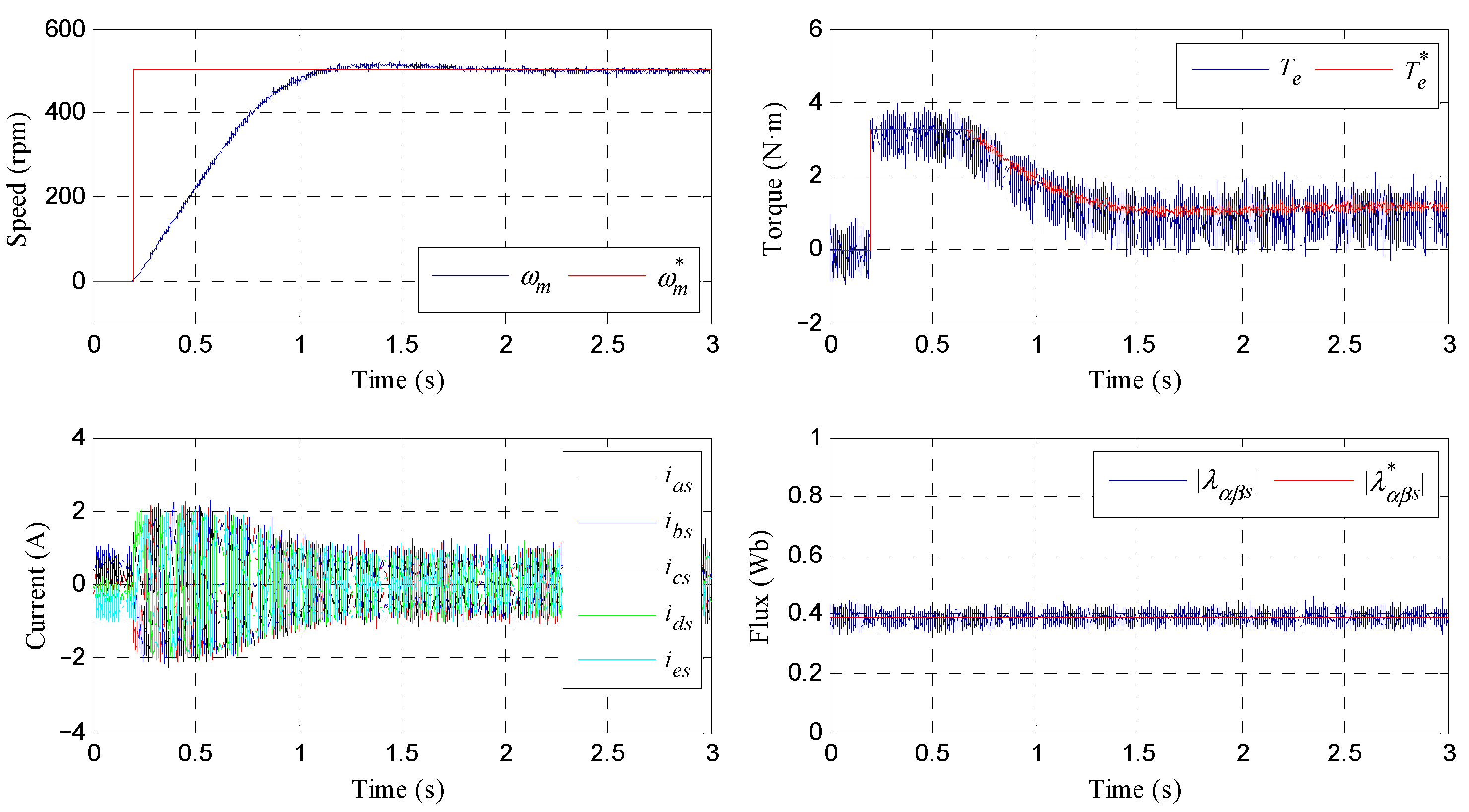
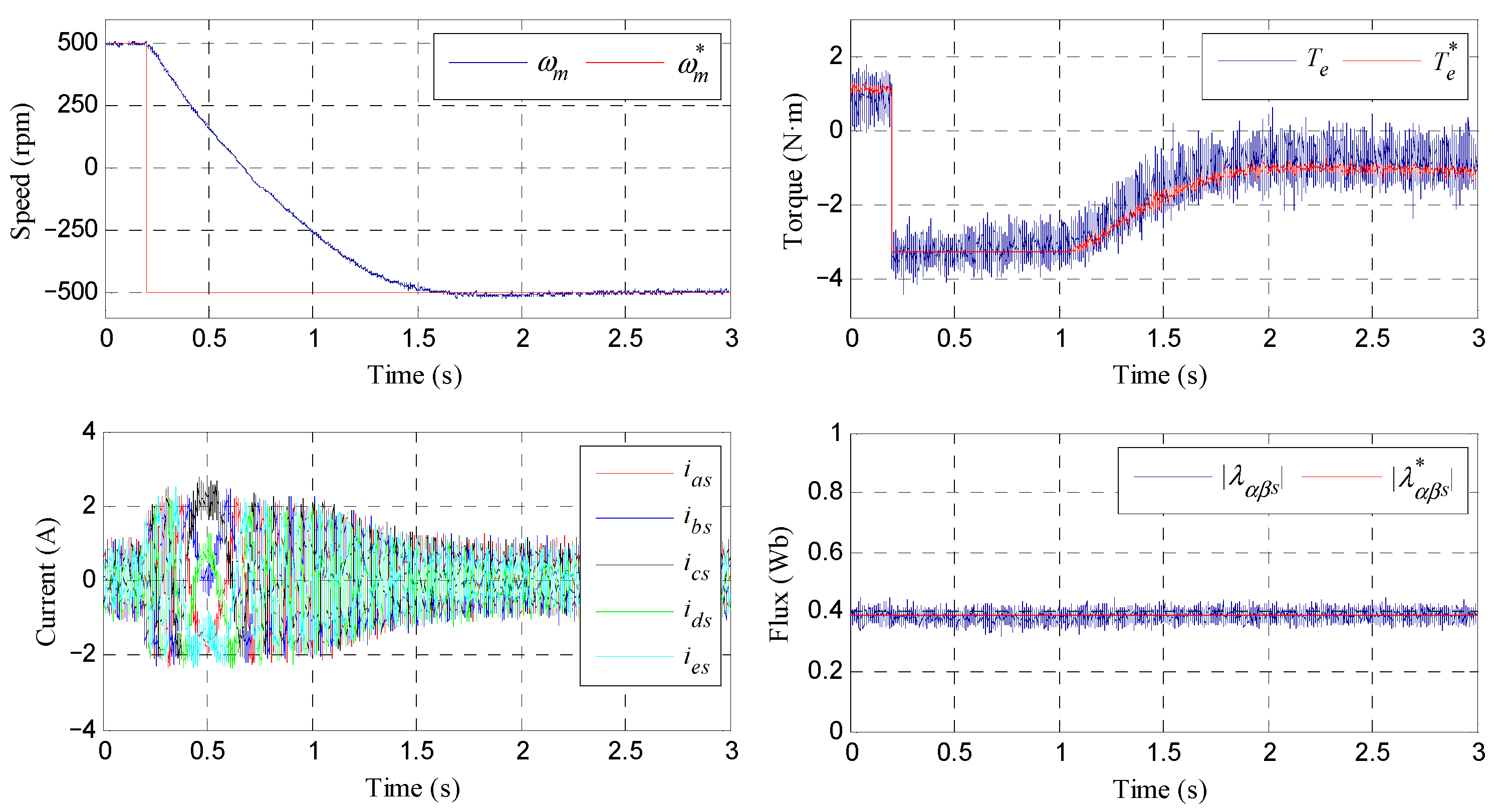
4.3. Step-Speed and Reverse Speed Tests

Then, experimental tests were conducted to evaluate the step-speed response of the system. Figure 12 reviews the results obtained. In the experiment, the machine is initially magnetized and the reference speed is changed from 0 to 500 rpm at t = 0.2 s. The performance of the mechanical speed (upper row, left plot), the electrical torque (upper row, right figure), stator phase currents (bottom row, left illustration), and the stator flux (bottom row, right drawing) is shown. Again, it can be observed that the DTC scheme provides accurate tracking of the reference speed and electrical torque, while the stator flux is maintained constant and equal to the reference value.
Finally, a reverse speed test is generated, where a change in the reference speed from 500 to –500 rpm is forced at t = 0.2 s. The obtained results are shown in Figure 13. Appropriate tracking is observed in the speed and the electrical torque, as can be seen in the upper row plots, left and right ones, respectively, while the expected stator phase current performance is observed close to the zero-speed crossing operating point (see lower row, left plot). Note that a saturation value of the reference torque (TMAX) is set to 3.25 N·m, being the stator flux constant and equal to the reference value.

4.4. Fault-Tolerant Capability

In our work, the fault-tolerant capability of the system using the DTC controller is also analyzed. First, we consider an open-phase fault operation and later take into account the operation with two consecutive and nonconsecutive faults. Figure 14, Figure 15 and Figure 16 show the performance of the mechanical speed and healthy stator currents when faults appear at t = 0.2 s. The system is operated as explained above with a load torque of 2.75 N·m. Figure 14 summarizes the behavior when phase a is open, while Figure 15 and Figure 16 show the performance when consecutive phases a and b and non-consecutive a and c, respectively, are open. It is interesting to note that there is no degradation of the speed tracking in all cases; although, the stator phase currents show unequal peak values in the faulty system that becomes worse if the number of faulty phases increases.
Although the use of DTC is not habitual in the field of multiphase drives due to the intrinsic limitations of a method that only manages two degrees of freedom, it has been experimentally validated that it is possible to apply it to five-phase IM as long as a series of virtual voltage vectors is created to impose zero voltage in the non-controllable plane of xy. This allows DTC to be successfully applied when the machine does not have notable asymmetries in the design, where DTC can be considered as a quite competitive alternative to conventional and more complex field-oriented controllers. The results obtained, which can be summarized in Table 3, can be easily extended to multiphase drives with a higher number of phases, but the required virtual voltage vectors must be redefined to minimize stator voltage vectors in the xy planes, which justifies considering the DTC technique as a stimulating strategy for the multiphase case.

5. Conclusions

Direct torque control emerged in the late 20th century to become an alternative to vector controllers in conventional three-phase drives, where robustness, simplicity, and computational cost were desirable regulation characteristics. However, it does not seem to be an adequate control technique if the number of phases of the drive increases, due to its ability to command two electrical magnitudes in the drive: the electrical torque and the stator flux. We note that interest in DTC has been barely explored or experimentally analyzed in multiphase drives, this paper therefore tries to reduce this gap, proposing DTC in managing normal and faulty operations of five-phase induction motor drives, where the application of DTC goes from the introduction of the virtual voltage vector concept, to resemble the number of freedom degrees of the system, to the conventional three-phase drive case. Virtual voltage vectors can easily extend the use of DTC to multiphase drives with a higher number of phases, as long as they are chosen to nullify the stator voltage and current components in all xy planes. Experimental evaluations were carried out using a test bed, and operating the drive in normal and faulty conditions (one and two open phases), with speed, torque, and flux references successfully tracked in all cases. The results obtained reveal that DTC is viable and can be extended to the case of multiphase drives, particularly where the required control goals are robustness, computational cost, and natural fault-tolerant capability of the drive in post-fault mode, without changing the control structure and/or current references.

Author Contributions

Conceptualization, M.B., F.B., C.M. and M.P.; methodology, M.B., F.B., C.M. and M.P.; software, M.B.; validation, M.B., F.B., C.M. and M.P.; formal analysis, M.B., F.B., C.M. and M.P.; investigation, M.B., F.B., C.M. and M.P.; resources, M.B., F.B., C.M. and M.P.; data curation, M.B. and C.M.; writing—original draft preparation, F.B.; writing—review and editing, M.B., F.B., C.M. and M.P.; visualization, M.B., F.B., C.M. and M.P.; supervision, F.B.; project administration, F.B.; funding acquisition, F.B. All authors have read and agreed to the published version of the manuscript.

Funding

This research received no external funding.

Conflicts of Interest

The authors declare that they have no conflict of interest.

References

  1. Warg, E.E.; Härer, H. Preliminary investigation of an inventor-fed 5-phase induction motor. Proc. Inst. Electr. Eng. 1969, 116, 980–984. [Google Scholar]
  2. Jahns, T.M. Improved reliability in solid-state AC drives by means of multiple independent phase drive units. IEEE Trans. Ind. Appl. 1980, IA-16, 321–331. [Google Scholar] [CrossRef]
  3. Toliyat, H.A.; Lipo, T.A.; White, J.C. Analysis of a concentrated winding induction machine for adjustable speed drive applications. I. Motor analysis. IEEE Trans. Energy Convers. 1991, 6, 679–683. [Google Scholar] [CrossRef]
  4. Levi, E.; Bojoi, R.; Profumo, F.; Toliyat, H.A.; Williamson, S. Multiphase induction motor drives—A technology status review. IET Electr. Power Appl. 2007, 1, 489–516. [Google Scholar] [CrossRef] [Green Version]
  5. Levi, E. Multiphase electric machines for variable-speed applications. IEEE Trans. Ind. Electron. 2008, 55, 1893–1909. [Google Scholar] [CrossRef]
  6. Bojoi, R.; Rubino, S.; Tenconi, A.; Vaschetto, S. Multiphase electrical machines and drives: A viable solution for energy generation and transportation electrification. In Proceedings of the 2016 International Conference and Exposition on Electrical and Power Engineering (EPE), Iasi, Romania, 20–22 October 2016; pp. 632–639. [Google Scholar]
  7. Cao, W.; Mecrow, B.C.; Atkinson, G.J.; Bennett, J.W.; Atkinson, D.J. Overview of electric motor technologies used for more electric aircraft (MEA). IEEE Trans. Ind. Electron. 2012, 59, 3523–3531. [Google Scholar]
  8. Barrero, F.; Duran, M.J. Recent advances in the design, modeling, and control of multiphase machines—Part I. IEEE Trans. Ind. Electron. 2016, 63, 449–458. [Google Scholar] [CrossRef]
  9. Duran, M.J.; Barrero, F. Recent advances in the design, modeling, and control of multiphase machines—Part II. IEEE Trans. Ind. Electron. 2016, 63, 459–468. [Google Scholar] [CrossRef]
  10. Duran, M.J.; Levi, E.; Barrero, F. Multiphase electric drives: Introduction. In Wiley Encyclopedia of Electrical and Electronics Engineering; Wiley: Hoboken, NJ, USA, 2017. [Google Scholar]
  11. Barrero, F.; González, I. Control of Multiphase Machines and Drives; MDPI: Basel, Switzerland, 2020; ISBN 978-3-03928-136-7. [Google Scholar]
  12. Bermúdez, M.; Martín, C.; González, I.; Duran, M.J.; Arahal, M.R.; Barrero, F. Predictive current control in electrical drives: An illustrated review with case examples using a five-phase induction motor drive with distributed windings. IET Electr. Power Appl. 2020, 14, 1291–1310. [Google Scholar] [CrossRef]
  13. Arahal, M.R.; Martin, C.; Barrero, F.; Duran, M.J. Assessing variable sampling time controllers for five-phase induction motor drives. IEEE Trans. Ind. Electron. 2020, 67, 2523–2531. [Google Scholar] [CrossRef]
  14. Arahal, M.R.; Satué, M.G.; Barrero, F.; Ortega, M.G. Adaptive Cost Function FCSMPC for 6-Phase IMs. Energies 2021, 14, 5222. [Google Scholar] [CrossRef]
  15. Takahashi, I.; Noguchi, T. A New Quick-Response and High-Efficiency Control Strategy of an Induction Motor. IEEE Trans. Ind. Appl. 1986, IA-22, 820–827. [Google Scholar] [CrossRef]
  16. Depenbrock, M. Direct self-control (DSC) of inverter-fed induction machine. IEEE Trans. Power Electron. 1988, 3, 420–429. [Google Scholar] [CrossRef]
  17. Fei, Y.; Xiaofeng, Z.; Minzhong, Q.; Chengdong, D. The direct torque control of multiphase permanent magnet synchronous motor based on low harmonic space vector PWM. In Proceedings of the IEEE International Conference on Industrial Technology (ICIT-2008), Chengdu, China, 21–24 April 2008; pp. 1–5. [Google Scholar]
  18. ABB Group. DTC: A Motor Control Technique for All Seasons. ABB White Paper. 2015. Available online: http://library.e.abb.com/public/0e07ab6a2de30809c1257e2d0042db5e/ABB_WhitePaper_DTC_A4_20150414.pdf (accessed on 27 October 2021).
  19. Hadiouche, D.; Razik, H.; Rezzoug, A. On the modeling and design of dual-stator windings to minimize circulating harmonic currents for VSI fed AC machines. IEEE Trans. Ind. Appl. 2004, 40, 506–515. [Google Scholar] [CrossRef]
  20. Buja, G.S.; Kazmierkowski, M.P. Direct torque control of PWM inverter-fed AC motors—A survey. IEEE Trans. Ind. Electron. 2004, 51, 744–757. [Google Scholar] [CrossRef]
  21. Kianinezhad, R.; Nahid, B.; Betin, F.; Capolino, G.A. A novel Direct Torque Control (DTC) method for dual three phase induction motors. In Proceedings of the IEEE International Conference on Industrial Technology (ICIT 2006), Mumbai, India, 15–17 December 2006; pp. 939–943. [Google Scholar]
  22. Kianinezhad, R.; Alcharea, R.; Nahid, B.; Betin, F.; Capolino, G.A. A novel direct torque control (DTC) for six-phase induction motors with common neutrals. In Proceedings of the International Symposium on Power Electronics, Electrical Drives, Automation and Motion (SPEEDAM 2008), Ischia, Italy, 11–13 June 2008; pp. 107–112. [Google Scholar]
  23. Zheng, L.; Fletcher, J.E.; Williams, B.W.; He, X. A Novel Direct Torque Control Scheme for a Sensorless Five-Phase Induction Motor Drive. IEEE Trans. Ind. Electron. 2011, 58, 503–513. [Google Scholar] [CrossRef]
  24. Parsa, L.; Toliyat, H.A. Sensorless Direct Torque Control of Five-Phase Interior Permanent-Magnet Motor Drives. IEEE Trans. Ind. Appl. 2007, 43, 952–959. [Google Scholar] [CrossRef]
  25. Gao, Y.; Parsa, L. Modified Direct Torque Control of Five-Phase Permanent Magnet Synchronous Motor Drives. In Proceedings of the 22nd Annual IEEE Applied Power Electronics Conference and Exposition (APEC 2007), Anaheim, CA, USA, 25 February–1 March 2007; pp. 1428–1433. [Google Scholar]
  26. Gao, L.; Fletcher, J.E.; Zheng, L. Low-Speed Control Improvements for a Two-Level Five-Phase Inverter-Fed Induction Machine Using Classic Direct Torque Control. IEEE Trans. Ind. Electron. 2011, 58, 2744–2754. [Google Scholar] [CrossRef]
  27. Riveros, J.A.; Duran, M.J.; Barrero, F.; Toral, S. Direct torque control for five-phase induction motor drives with reduced common-mode voltage. In Proceedings of the 38th Annual Conference on IEEE Industrial Electronics Society (IECON 2012), Montreal, QC, Canada, 25–28 October 2012; pp. 3616–3621. [Google Scholar]
  28. Tatte, Y.N.; Aware, M.V. Direct Torque Control of Five-Phase Induction Motor with Common-Mode Voltage and Current Harmonics Reduction. IEEE Trans. Power Electron. 2017, 32, 8644–8654. [Google Scholar] [CrossRef]
  29. Chikondra, B.; Muduli, U.R.; Behera, R.K. An Improved Open-Phase Fault-Tolerant DTC Technique for Five-Phase Induction Motor Drive Based on Virtual Vectors Assessment. IEEE Trans. Ind. Electron. 2021, 68, 4598–4609. [Google Scholar] [CrossRef]
  30. Barrero, F.; Bermúdez, M.; Durán, M.J.; Salas, P.; González-Prieto, I. Assessment of a Universal Reconfiguration-less Control Approach in Open-Phase Fault Operation for Multiphase Drives. Energies 2019, 12, 4698. [Google Scholar] [CrossRef] [Green Version]
  31. Bermúdez, M.; González-Prieto, I.; Barrero, F.; Guzmán, H.; Duran, M.J.; Kestelyn, X. Open-Phase Fault-Tolerant Direct Torque Control Technique for Five-Phase Induction Motor Drives. IEEE Trans. Ind. Electron. 2017, 64, 902–911. [Google Scholar] [CrossRef] [Green Version]
  32. Bermúdez, M.; González-Prieto, I.; Barrero, F.; Guzmán, H.; Kestelyn, X.; Duran, M.J. An Experimental Assessment of Open-Phase Fault-Tolerant Virtual-Vector-Based Direct Torque Control in Five-Phase Induction Motor Drives. IEEE Trans. Power Electron. 2018, 33, 2774–2784. [Google Scholar] [CrossRef] [Green Version]
Figure 1. Schematic diagram of the case study.
Applsci 11 11964 g001
Figure 2. Mapping of the phase stator voltages of the two-level five-phase VSI in the αβ (left graph) and xy (right graph) planes.
Applsci 11 11964 g002
Figure 3. Reference frames for modeling the electrical machine.
Applsci 11 11964 g003
Figure 4. Impact of voltage vectors on the stator flux and the load angle for the application of DTC. (a) Estimated phasor diagram. (b) Alternatives available using the 2-level 5-phase VSI.
Applsci 11 11964 g004
Figure 5. VVL1 projections in the (a) αβ plane and (b) xy plane.
Applsci 11 11964 g005
Figure 6. Virtual voltage vectors in the αβ plane.
Applsci 11 11964 g006
Figure 7. DTC scheme.
Applsci 11 11964 g007
Figure 8. Experimental test rig.
Applsci 11 11964 g008
Figure 9. Experimental steady-state operation test where the reference speed is settled at 500 rpm and a load torque of 1 N·m is applied. Upper row: speed and torque responses. Second row: stator flux waveforms. Third row: current trajectories of the stator in the αβ and xy planes. Last row: stator phase currents.
Applsci 11 11964 g009
Figure 10. Experimental steady-state operation test where the reference speed is set at 500 rpm and a load torque of 2.75 N·m is applied. Upper row: speed and torque responses. Second row: stator flux waveforms. Third row: current trajectories of the stator in the αβ and xy planes. Last row: stator phase currents.
Applsci 11 11964 g010
Figure 11. Experimental response of the controlled system in a load torque rejection test. The reference speed is 500 rpm and a load torque is applied at 0.5 s. The upper row shows the speed and torque responses. The lower row shows the stator current waveform and modulus of the stator flux during the test.
Applsci 11 11964 g011
Figure 12. Experimental response of the controlled system in a step speed test. The reference speed is changed from 0 to 500 rpm at 0.2 s. The upper row shows the speed and torque responses. The lower row shows the stator current waveform and modulus of the stator flux during the test.
Applsci 11 11964 g012
Figure 13. Experimental response of the controlled system in a speed reversal test. The reference speed is changed from 500 to −500 rpm at 0.2 s. The upper row shows the speed and torque responses. The lower row shows the stator current waveform and modulus of the stator flux during the test.
Applsci 11 11964 g013
Figure 14. Experimental response of the controlled system when stator phase a is open at t = 0.2 s and the system is controlled at 500 rpm. The upper row shows the speed response and the lower one shows the stator current waveforms corresponding to phases b, c, d, and e during the test.
Applsci 11 11964 g014
Figure 15. Experimental response of the controlled system when stator phases a and b are open at t = 0.2 s and the system is controlled at 500 rpm. The upper row shows the speed response, and the lower one depicts the stator current waveforms corresponding to phases c, d, and e during the test.
Applsci 11 11964 g015
Figure 16. Experimental response of the controlled system when stator phase a and c are open at t = 0.2 s and the system is controlled at 500 rpm. The upper row shows the speed response, and the lower one depicts the stator current waveforms corresponding to phases b, d, and e during the test.
Applsci 11 11964 g016
Table 1. Lookup control table.
dTPosition of the Stator Flux (Sector)
12345678910
+1+2+1VVL3VVL4VVL5VVL6VVL7VVL8VVL9VVL10VVL1VVL2
−1VVL2VVL3VVL4VVL5VVL6VVL7VVL8VVL9VVL10VVL1
+1+1VVS3VVS4VVS5VVS6VVS7VVS8VVS9VVS10VVS1VVS2
−1VVS2VVS3VVS4VVS5VVS6VVS7VVS8VVS9VVS10VVS1
0+1v0v31v0v31v0v31v0v31v0v31
−1v0v31v0v31v0v31v0v31v0v31
−1+1VVS9VVS10VVS1VVS2VVS3VVS4VVS5VVS6VVS7VVS8
−1VVS10VVS1VVS2VVS3VVS4VVS5VVS6VVS7VVS8VVS9
−2+1VVL9VVL10VVL1VVL2VVL3VVL4VVL5VVL6VVL7VVL8
−1VVL10VVL1VVL2VVL3VVL4VVL5VVL6VVL7VVL8VVL9
−1+2+1VVL4VVL5VVL6VVL7VVL8VVL9VVL10VVL1VVL2VVL3
−1VVL5VVL6VVL7VVL8VVL9VVL10VVL1VVL2VVL3VVL4
+1+1VVS4VVS5VVS6VVS7VVS8VVS9VVS10VVS1VVS2VVS3
−1VVS5VVS6VVS7VVS8VVS9VVS10VVS1VVS2VVS3VVS4
0+1v31v0v31v0v31v0v31v0v31v0
−1v31v0v31v0v31v0v31v0v31v0
−1+1VVS8VVS9VVS10VVS1VVS2VVS3VVS4VVS5VVS6VVS7
−1VVS7VVS8VVS9VVS10VVS1VVS2VVS3VVS4VVS5VVS6
−2+1VVL8VVL9VVL10VVL1VVL2VVL3VVL4VVL5VVL6VVL7
−1VVL7VVL8VVL9VVL10VVL1VVL2VVL3VVL4VVL5VVL6
Table 2. Electrical and mechanical parameters of the five-phase IM.
ParameterValueUnit
Stator resistance, Rs12.85Ω
Rotor resistance, Rr4.80Ω
Stator leakage inductance, Lls79.93mH
Rotor leakage inductance, Llr79.93mH
Mutual inductance, M681.7mH
Rotational inertia, Jm0.02kg-m2
Number of pairs of poles, p3-
Table 3. Qualitative analysis of the performance of the 5-phase IM drive using DTC.
Closed-Loop System PerformanceDTC
Speed tracking error when the fault appearsNegligible
Torque tracking loss in control during the delayNo
Robustness against fault detection delayHigh
Computational costLow
Harmonic content in stator currentsHigh
Publisher’s Note: MDPI stays neutral with regard to jurisdictional claims in published maps and institutional affiliations.

