
Influence of Double-Limb Double-Plate Connection on Stable Bearing Capacity of Quadrilateral Transmission Tower


Abstract
:1. Introduction
2. Bearing Capacity Test of Double-Limb Double-Plate Joint
2.1. Test Purpose
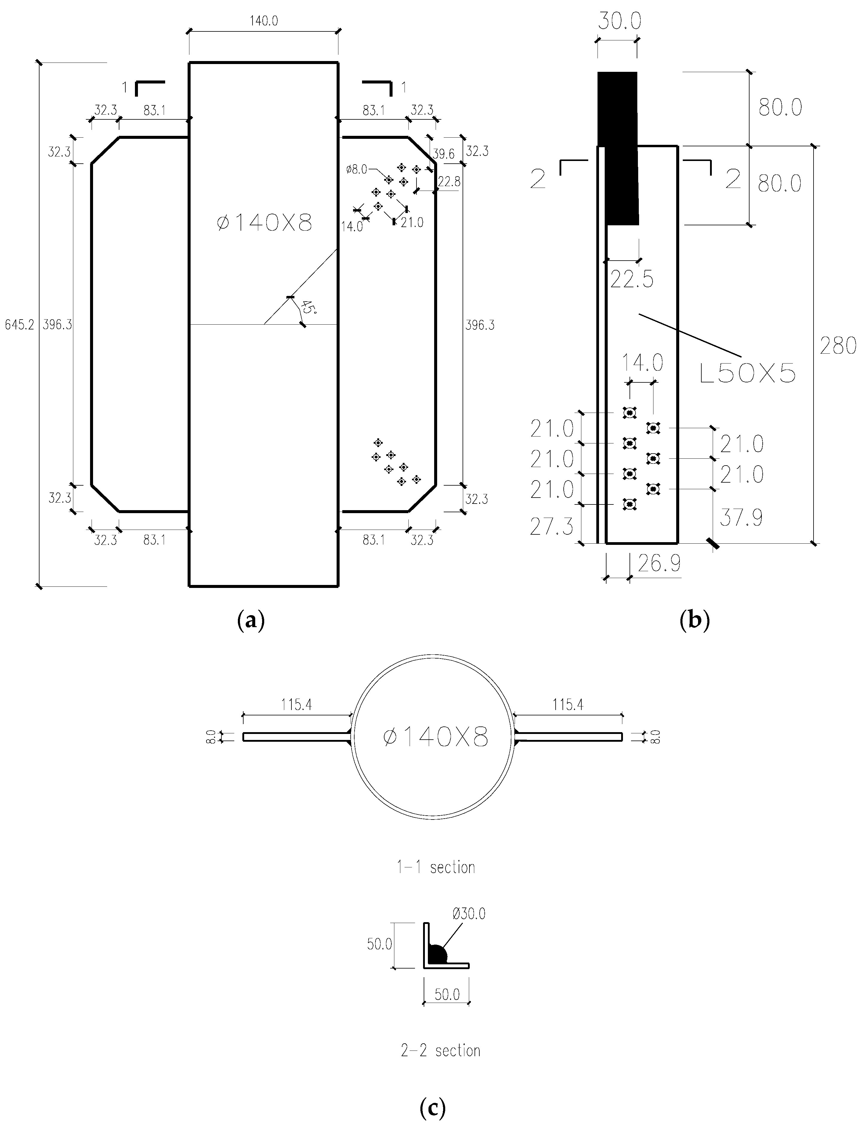
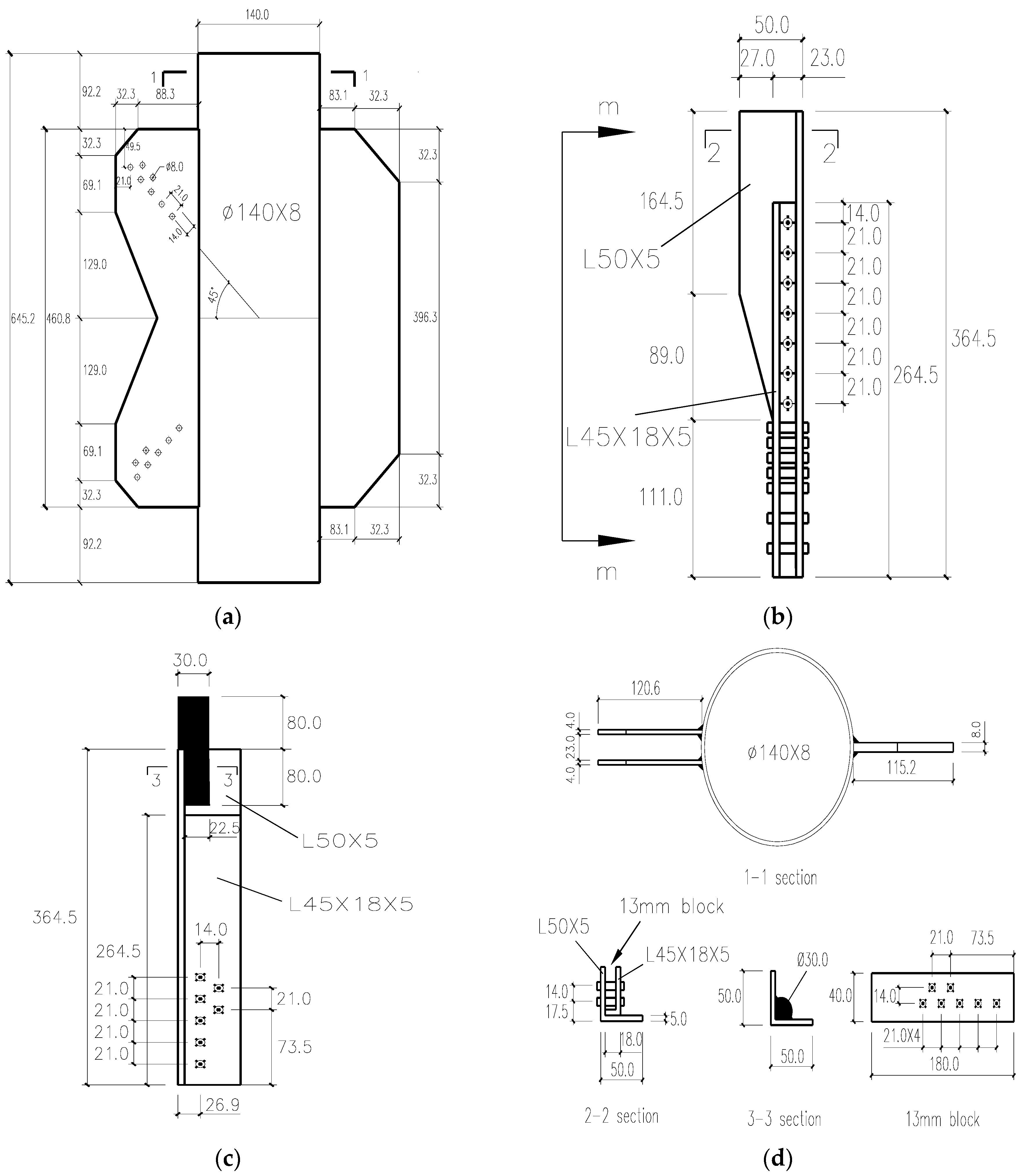
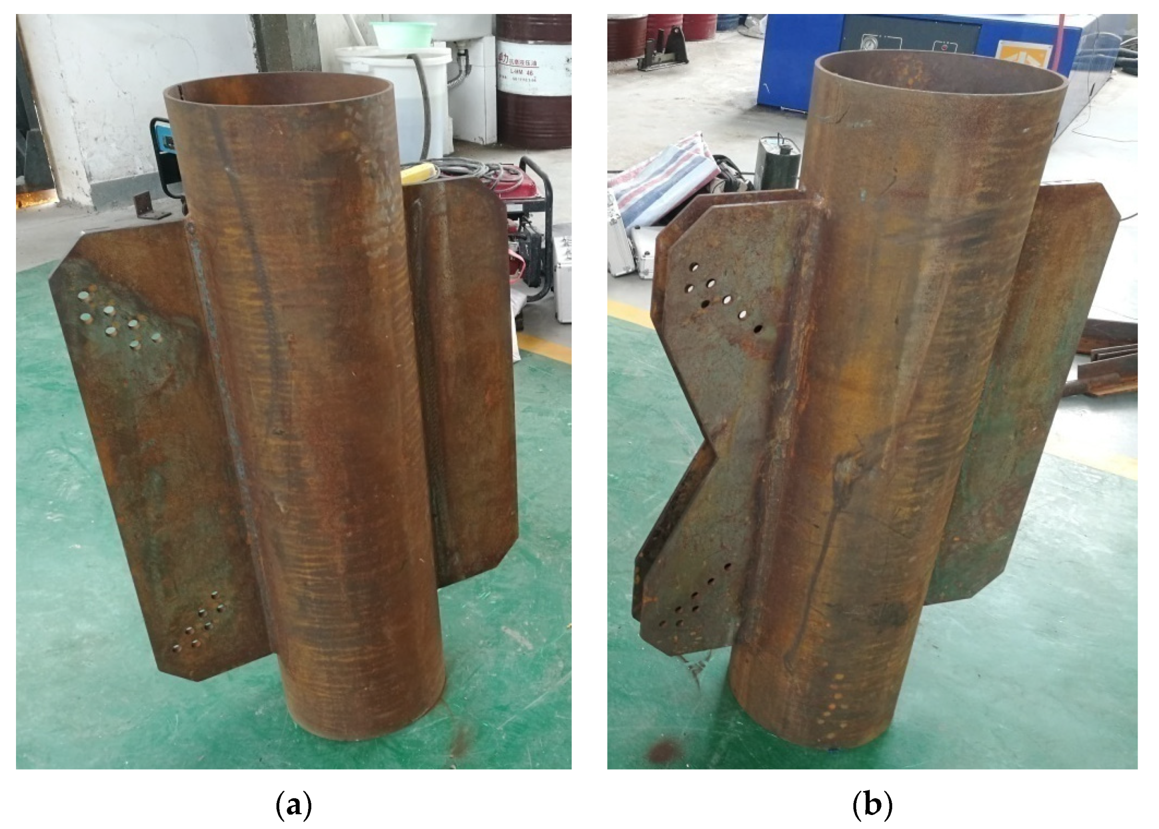
2.2. Test Model
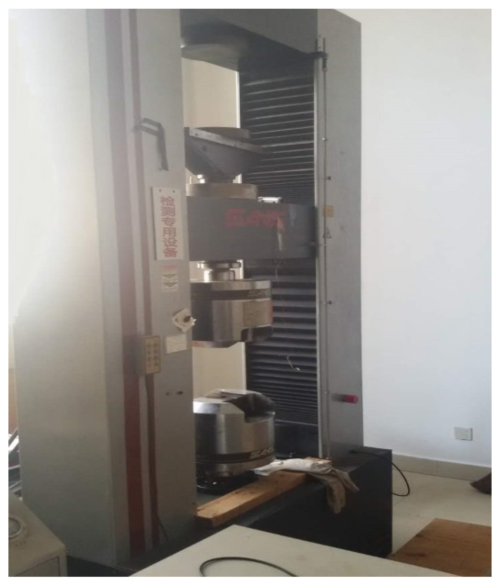
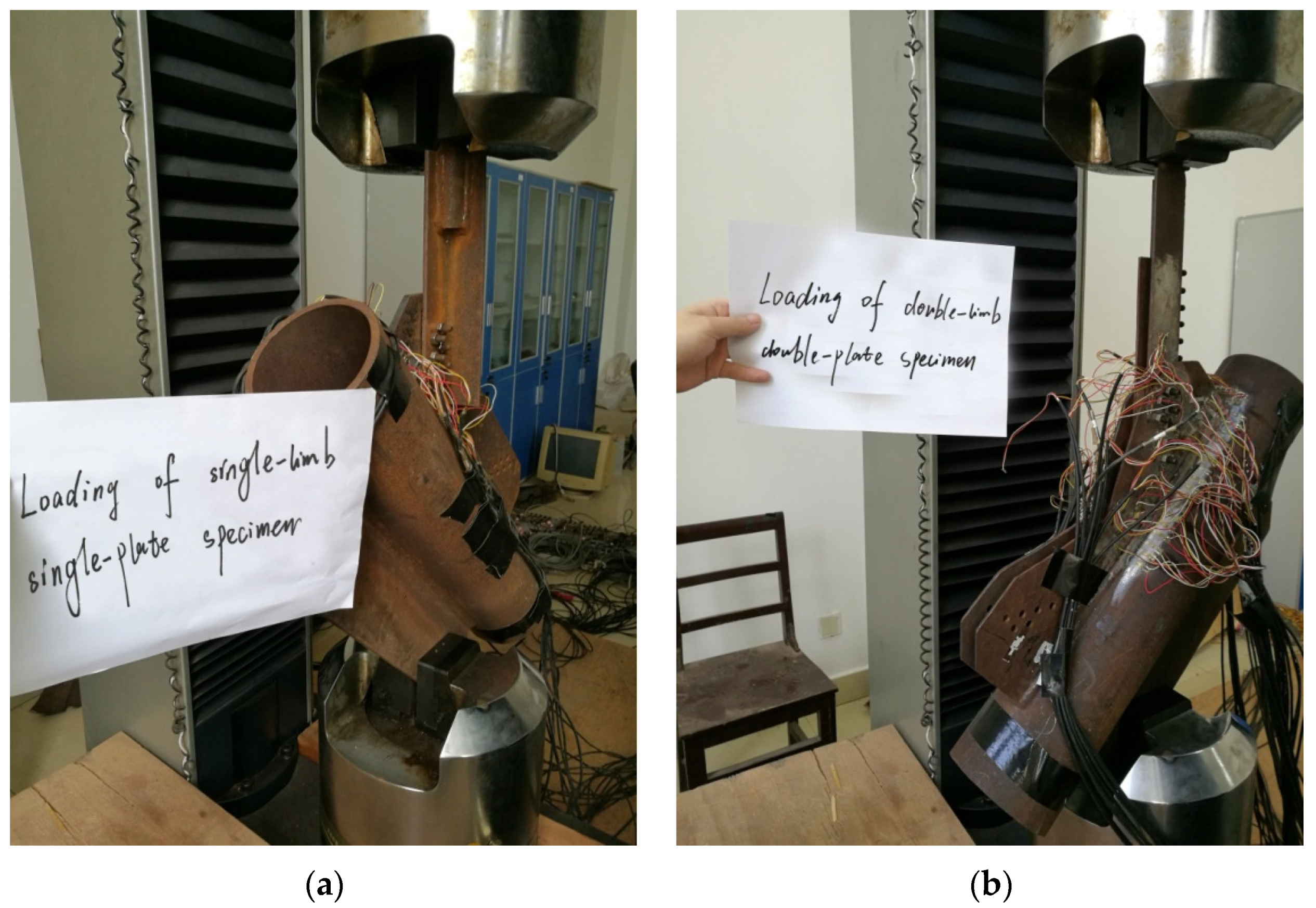
2.3. Loading System and Test Loading Device
- The first six stages of loading in the test shall be loaded from zero to 60 kN, and each stage of loading shall be increased by 10 kN. After each stage of loading is maintained for 30 s, the corresponding load strain and displacement values shall be recorded.
- After that, it is loaded to 100 kN in two stages, and each stage is increased by 20 kN. After each stage of loading is maintained for 30 s, the corresponding load strain and displacement values shall be recorded.
- Finally, load until the test specimen is damaged, after each stage is loaded with 10 kN and maintained for 30 s, collect data until the specimen is damaged.
- The first six stages of loading in the test shall be loaded from zero to 60 kN, and each stage of loading shall be increased by 10 kN. After each stage of loading is maintained for 30 s, the corresponding load strain and displacement values shall be recorded.
- After that, it is loaded to 105 kN in three stages, and each stage is increased by 15 kN. After each stage of loading is maintained for 30 s, the corresponding load strain and displacement values shall be recorded.
- Load to the design ultimate load of the test piece, and load it to 150 kN in three levels, with an increase of 15 kN for each level.
- Finally, load until the specimen is damaged, load 10 kN at each stage and collect data after each stage is loaded with 10 kN and maintained for 30 s until the specimen is damaged.
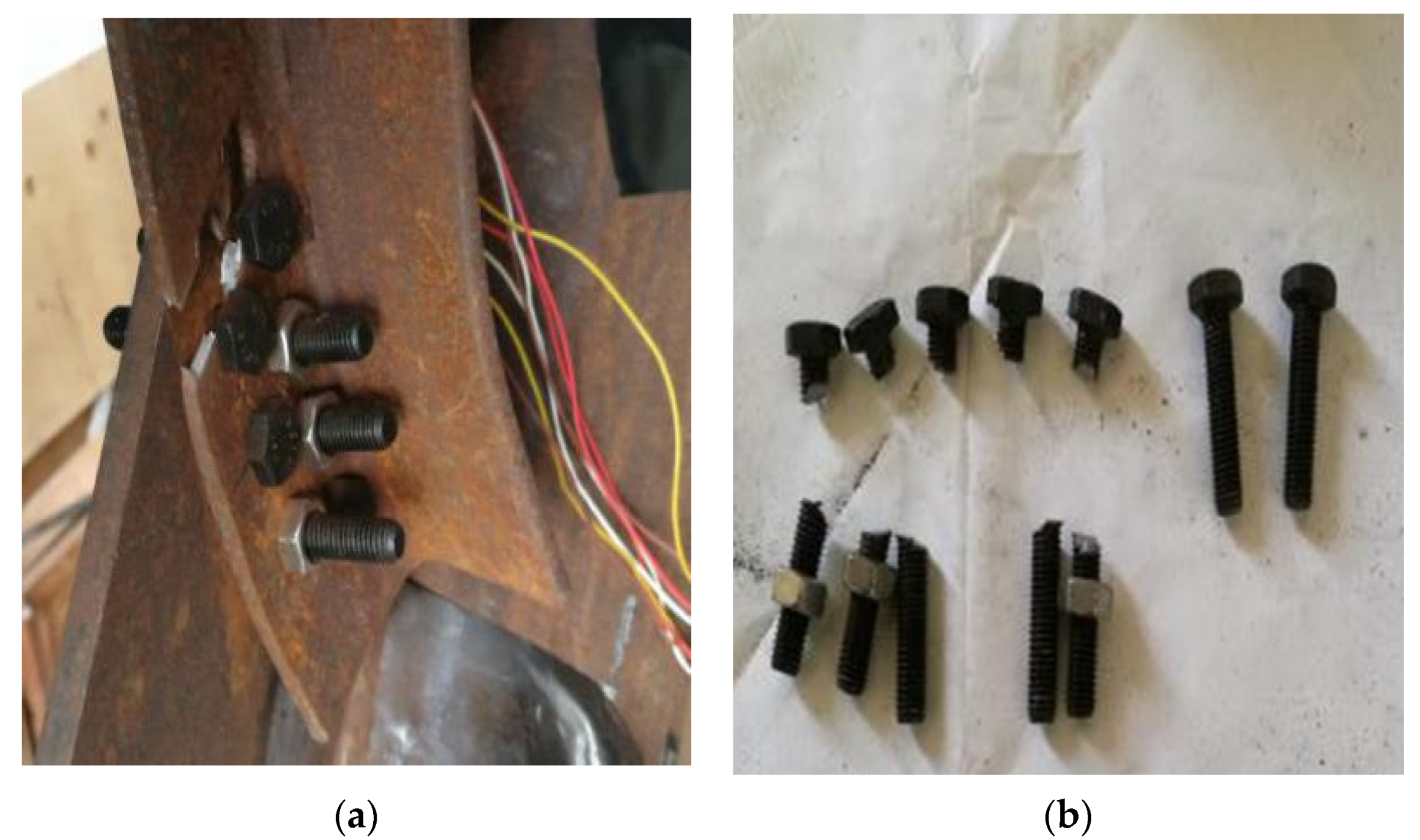
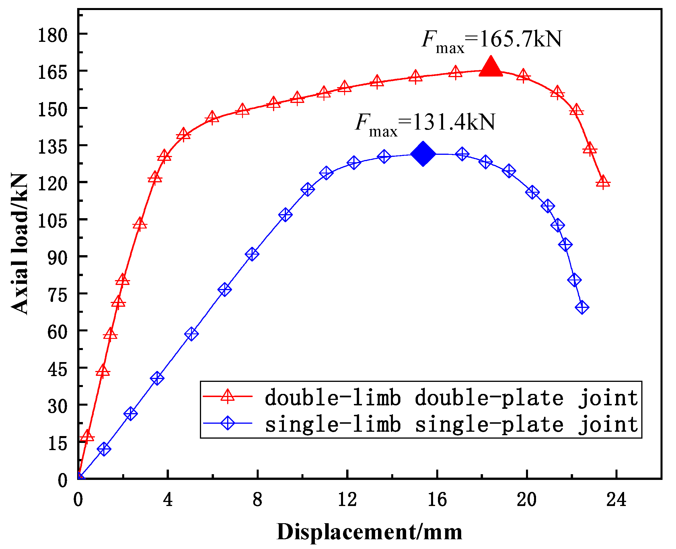
2.4. Test Results
3. Calculation Method of Stable Bearing Capacity of Tower
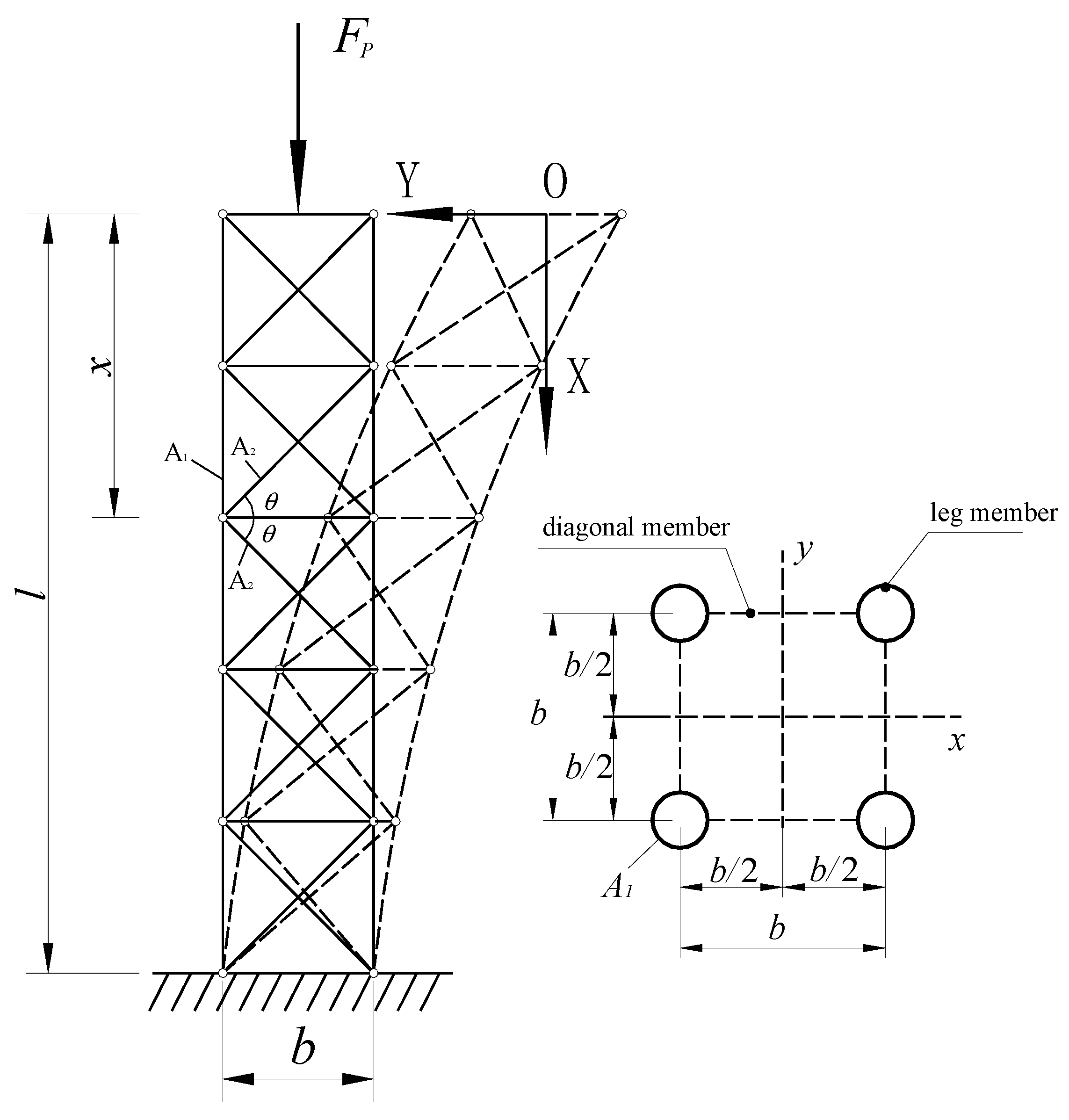
3.1. Stable Bearing Capacity of Tower without Considering the Influence of Joint Axis Stiffness
3.2. Stable Bearing Capacity of Tower Considering the Influence of Joint Axis Stiffness
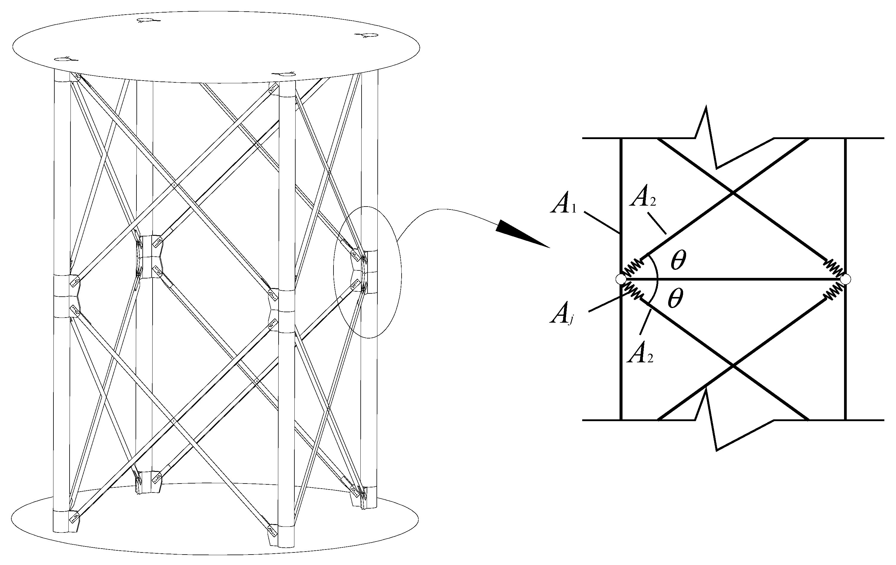
3.3. Influence Coefficient of Axial Stiffness of Joints
4. Comparative Analysis of Theory and Finite Element Numerical Simulation
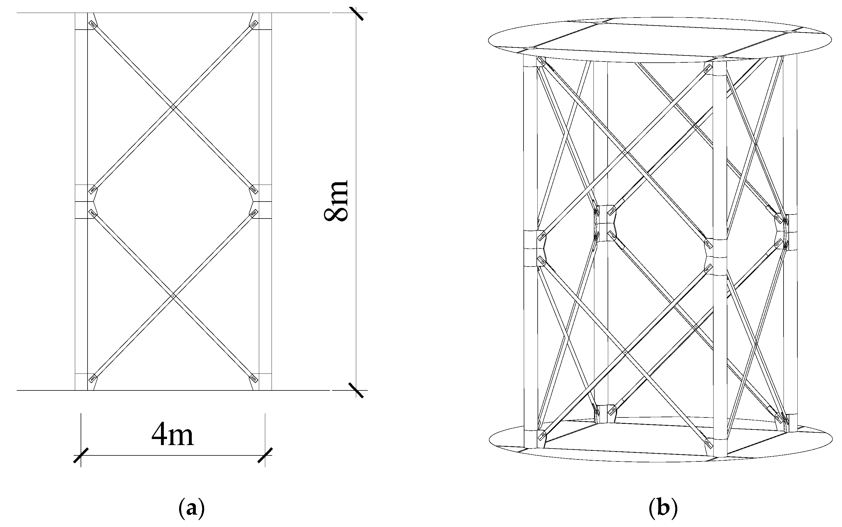
4.1. Finite Element Model
4.2. Finite Element Results Analysis
5. Conclusions
- The scale test results of single-limb single-plate and double-limb double-plate connection joints show that the bearing capacity of double-limb double-plate connection joint can be increased by 26.1%. The load displacement curve of the joint shows that the elastic stiffness of double-limb double-plate connection joint is 3.12 times that of single-limb single-plate connection joint.
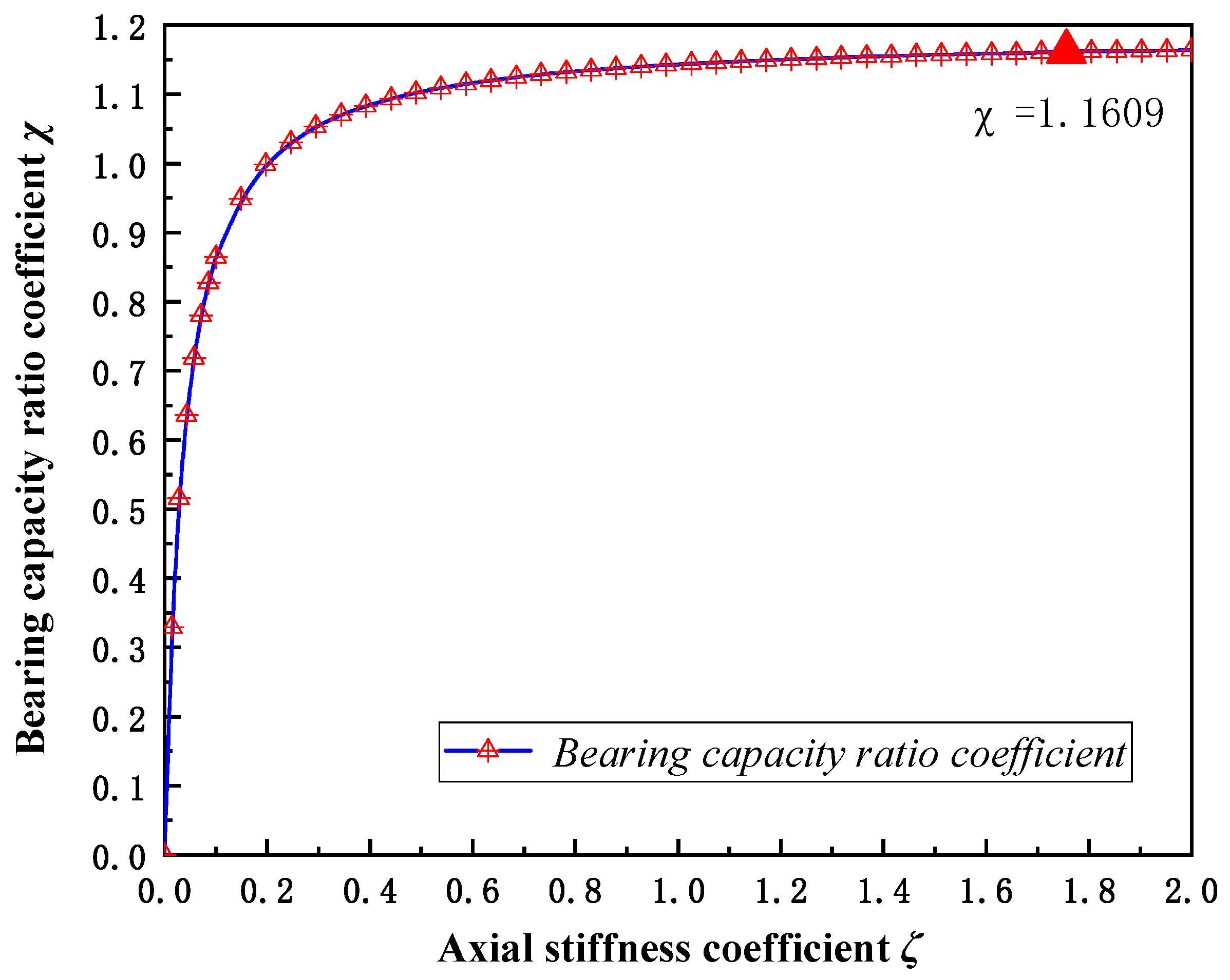
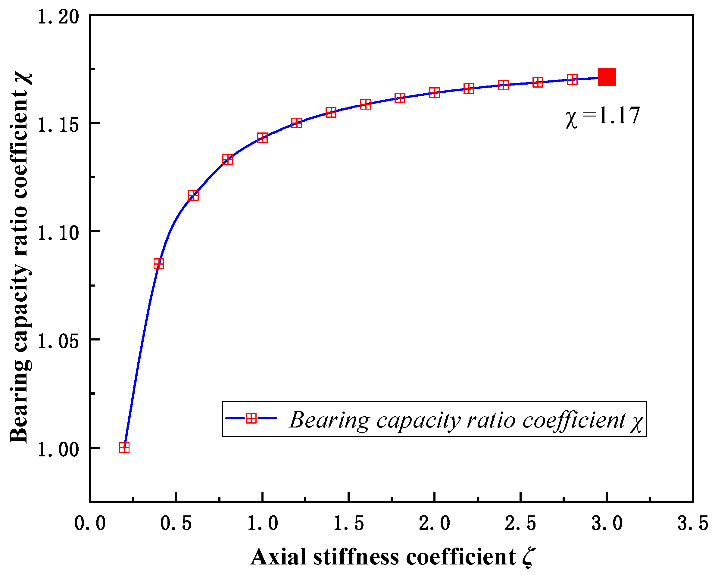
- The influence of the axial stiffness of the joint on the stable bearing capacity of the quadrilateral tower is studied by the energy method. The axial stiffness coefficient is introduced to express the influence of the change of the joint stiffness on the stable bearing capacity of the tower. The results show that with the increase of the axial stiffness coefficient, the stable bearing capacity of the tower first increases and then tends to be stable, and the axial stiffness coefficient has the greatest influence in the range of 0~0.5.
- Combined with the joint test and theoretical analysis, it is found that the DLDPJ can improve the stable bearing capacity of quadrilateral tower by 15.6%.
- The quadrilateral tower numerical model of the test model joint is established, and the whole process of nonlinear buckling of the tower is analyzed. Considering the influence of geometric nonlinearity of the tower and connection joints, it is found that the double-limb double-plate connection joint can improve the nonlinear stability bearing capacity of the transmission tower by 14.9%.
Author Contributions
Funding
Institutional Review Board Statement
Informed Consent Statement
Data Availability Statement
Conflicts of Interest
References
- Murakawa, H.; Deng, D.; Ma, N.; Wang, J. Applications of inherent strain and interface element to simulation of welding deformation in thin plate structures. Comput. Mater. Sci. 2012, 51, 43–52. [Google Scholar] [CrossRef]
- Zhang, C.; Li, S.; Sun, J.; Wang, Y.; Deng, D. Controlling angular distortion in high strength low alloy steel thick-plate T-joints. J. Mater. Process. Technol. 2019, 267, 257–267. [Google Scholar] [CrossRef]
- Fu, X.; Du, W.; Li, H.; Li, G.; Dong, Z.; Yang, L. Stress state and failure path of a tension tower in a transmission line under multiple loading conditions. Thin-Walled Struct. 2020, 157, 107012. [Google Scholar] [CrossRef]
- Xie, Q.; Zhang, J. Experimental study on failure modes and retrofitting method of latticed transmission tower. Eng. Struct. 2021, 226, 111365. [Google Scholar] [CrossRef]
- Xue, J.; Xiang, Z.; Ou, G. Predicting single freestanding transmission tower time history response during complex wind input through a convolutional neural network based surrogate model. Eng. Struct. 2021, 233, 111859. [Google Scholar] [CrossRef]
- Roy, S.; Kundu, C.K. State of the art review of wind induced vibration and its control on transmission towers. Structures 2021, 29, 254–264. [Google Scholar] [CrossRef]
- Ma, H.; Zhao, Y.; Fan, F.; Yu, Z.; Zhi, X. Experimental and numerical study of new connection systems for a large-span hyperbolic steel cooling tower. Eng. Struct. 2019, 195, 452–468. [Google Scholar] [CrossRef]
- Ma, H.; Yu, Z.; Zhao, Y.; Fan, F. Behavior of HCR semi-rigid joints under complex loads and its effect on stability of steel cooling towers. Eng. Struct. 2020, 222, 111062. [Google Scholar] [CrossRef]
- Ma, H.; Zhao, Y.; Fan, F.; Xie, P. Nonlinear stability of steel cooling towers with semirigid connections. Thin-Walled Struct. 2021, 159, 107164. [Google Scholar] [CrossRef]
- Martins, D.; Gonilha, J.; Correia, J.R.; Silvestre, N. Monotonic and cyclic behaviour of a stainless steel cuff system for beam-to-column connections between pultruded I-section GFRP profiles. Eng. Struct. 2021, 249, 113294. [Google Scholar] [CrossRef]
- Zhang, A.; Xie, Z.; Zhang, Y.; Lin, H. Shaking table test of a prefabricated steel frame structure with all-bolted connections. Eng. Struct. 2021, 248, 113273. [Google Scholar] [CrossRef]
- Li, C.; Deng, H.; Gao, Y.; Song, X.; Hu, X. Compression analysis of external double-layered flange connection in transmission tower. Structures 2021, 33, 3002–3016. [Google Scholar] [CrossRef]
- Song, S.; Chen, J.; Xu, F. Mechanical behaviour and design of concrete-filled K and KK CHS connections. J. Constr. Steel Res. 2022, 188, 107000. [Google Scholar] [CrossRef]
- Tian, L.; Liu, J.; Chen, C.; Guo, L.; Wang, M.; Wang, Z. Experimental and numerical analysis of a novel tubular joint for transmission tower. J. Constr. Steel Res. 2020, 164, 105780. [Google Scholar] [CrossRef]
- Li, F.; Deng, H.; Hu, X. Experimental and numerical investigation into ultimate capacity of longitudinal plate-to-circular hollow section K- and DK-joints in transmission towers. Thin-Walled Struct. 2019, 143, 106240. [Google Scholar] [CrossRef]
- Li, F.; Deng, H.; Cai, Q.; Dong, J.; Fu, P. Experiment and design investigation of a multi-planar joint in a transmission tower. J. Constr. Steel Res. 2018, 149, 78–94. [Google Scholar] [CrossRef]
- Liu, H.; Han, J.; Sun, Z.; Yang, J.; Yang, F.; Xu, X. Efficient method to include joint zones of chord members in finite element model of tubular transmission tower at linear elastic stage. Int. J. Steel Struct. 2015, 15, 973–988. [Google Scholar] [CrossRef]
- He, X.; Chan, T.; Chung, K. Effect of inter-module connections on progressive collapse behaviour of MiC structures. J. Constr. Steel Res. 2021, 185, 106823. [Google Scholar] [CrossRef]
- Ma, R.; Yu, L.; Zhang, H.; Tan, L.; Ahmad, B.H.K.; Feng, J.; Cai, J. Experimental and numerical appraisal of steel joints integrated with single- and double-angles for transmission line towers. Thin-Walled Struct. 2021, 164, 107833. [Google Scholar] [CrossRef]
- Abdelrahman, A.H.A.; Liu, Y.; Chan, S. Advanced joint slip model for single-angle bolted connections considering various effects. Adv. Struct. Eng. 2020, 23, 2121–2135. [Google Scholar] [CrossRef]
- Gan, Y.; Deng, H.; Li, C. Simplified joint-slippage model of bolted joint in lattice transmission tower. Structures 2021, 32, 1192–1206. [Google Scholar] [CrossRef]
- An, L.; Wu, J.; Jiang, W. Experimental and numerical study of the axial stiffness of bolted joints in steel lattice transmission tower legs. Eng. Struct. 2019, 187, 490–503. [Google Scholar] [CrossRef]
- Balagopal, R.; Ramaswamy, A.; Palani, G.S.; Rao, N.P. Simplified bolted connection model for analysis of transmission line towers. Structures 2020, 27, 2114–2125. [Google Scholar] [CrossRef]
- Szafran, J.; Juszczyk, K.; Kamiński, M. Experiment-based reliability analysis of structural joints in a steel lattice tower. J. Constr. Steel Res. 2019, 154, 278–292. [Google Scholar] [CrossRef]
- De Souza, R.R.; Miguel, L.F.F.; Mcclure, G.; Alminhana, F.; Kaminski, J. Reliability assessment of existing transmission line towers considering mechanical model uncertainties. Eng. Struct. 2021, 237, 112016. [Google Scholar] [CrossRef]
- Yang, F.; Zhu, B.; Li, Z. Numerical analysis and full-scale experiment on K-joint deformations in the crank arms of lattice transmission towers. Struct. Des. Tall Spec. Build. 2018, 27, e1448. [Google Scholar] [CrossRef]
- Ahmed, K.I.E.; Rajapakse, R.K.N.D.; Gadala, M.S. Influence of Bolted-Joint Slippage on the Response of Transmission Towers Subjected to Frost-Heave. Adv. Struct. Eng. 2009, 12, 1–17. [Google Scholar] [CrossRef]
- Yan, H.; Nie, X.; Zhang, L.; Yang, F.; Huang, M.; Zhao, T. Test and Finite Element Analysis of a New Type of Double-Limb Double-Plate Connection Joint in Narrow Base Tower. Materials 2021, 14, 5936. [Google Scholar] [CrossRef]
- Ugural, A.C.; Fenster, S.K. Advanced Strength and Applied Elasticity; Prentice Hall: Upper Saddle River, NJ, USA, 1975; pp. 382–394. [Google Scholar]
- Huang, M.; Zhang, L.; Chen, Y.; Zhao, T. Oscillation periods of electric transmission lines with and without effect of bending deformation energy. J. Eng. Math. 2019, 119, 241–254. [Google Scholar] [CrossRef]
- Xu, K. Analysis and Application of ANSYS Building Structure; China Construction Industry Press: Beijing, China, 2013. [Google Scholar]


| Loading Stage | 1 | 2 | 3 | 4 | |
|---|---|---|---|---|---|
| Load size (kN) | SLSPJ | 60 | 100 | destruction | - |
| DLDPJ | 60 | 105 | 150 | destruction | |
Publisher’s Note: MDPI stays neutral with regard to jurisdictional claims in published maps and institutional affiliations. |
© 2021 by the authors. Licensee MDPI, Basel, Switzerland. This article is an open access article distributed under the terms and conditions of the Creative Commons Attribution (CC BY) license (https://creativecommons.org/licenses/by/4.0/).
Share and Cite
Zhao, T.; Yan, H.; He, P.; Zhang, L.; Lan, Z.; Huang, M. Influence of Double-Limb Double-Plate Connection on Stable Bearing Capacity of Quadrilateral Transmission Tower. Appl. Sci. 2021, 11, 12024. https://doi.org/10.3390/app112412024
Zhao T, Yan H, He P, Zhang L, Lan Z, Huang M. Influence of Double-Limb Double-Plate Connection on Stable Bearing Capacity of Quadrilateral Transmission Tower. Applied Sciences. 2021; 11(24):12024. https://doi.org/10.3390/app112412024
Chicago/Turabian StyleZhao, Tengfei, Hong Yan, Panpan He, Lei Zhang, Zhiwen Lan, and Mojia Huang. 2021. "Influence of Double-Limb Double-Plate Connection on Stable Bearing Capacity of Quadrilateral Transmission Tower" Applied Sciences 11, no. 24: 12024. https://doi.org/10.3390/app112412024