Article

Numerical Study on Track–Bridge Interaction of Integral Railway Rigid-Frame Bridge

1
School of Civil Engineering, Central South University, Changsha 410075, China
2
Key Laboratory of Heavy Railway Engineering Structure of Education Ministry, Changsha 410075, China
3
China Railway Siyuan Survey and Design Group Co., Ltd., Wuhan 430063, China
*
Author to whom correspondence should be addressed.
Appl. Sci. 2021, 11(3), 922; https://doi.org/10.3390/app11030922
Submission received: 13 December 2020 / Revised: 14 January 2021 / Accepted: 18 January 2021 / Published: 20 January 2021
(This article belongs to the Special Issue Interactions between Railway Subsystems)

Abstract

:
Track–bridge interaction (TBI) is an increasingly essential consideration for the design and operation of railway bridges, especially for the innovative bridge structure systems that constantly spring up over the years. This paper focuses on the characteristics of additional forces in continuous welded rails (CWRs) on the 3 × 70 m integral rigid-frame bridge of the Fuzhou–Xiamen High-Speed Railway, which is a novel high-speed railway (HSR) bridge structure system in China. The differential equations of rail stress and displacement are first investigated and an integrative analysis model comprising of rail, track, bridge and piers is then established. Secondly, the characteristics of representative additional forces are illustrated and the influences of different design parameters are discussed in detail. Furthermore, suitable rail fasteners, optimal layout schemes of adjacent bridges and reasonable stiffness of piers are also studied. The results indicate that the additional expansion force accounts for the largest proportion of additional forces in integral rigid-frame bridges and that resistance reduction obviously weakens the various additional forces caused by the TBI effect, while the broken gap of the rail increases greatly. Small resistance fasteners are recommended to be applied onto this new type of HSR line as these provide reductions in additional stresses of CWRs compared to WJ-8 fasteners. The additional rail stresses after adopting an adjacent span scheme of 4 × 32 m simply supported beams are less than the corresponding stresses in other schemes. The results also show that there is a strong correlation between the minimum threshold value of the pier stiffness and the longitudinal resistance of HSR lines for the integral rigid-frame bridge. This work could serve as a valuable reference for detailed design and safety evaluation of integral rigid-frame bridges.

1. Introduction

Track–bridge interaction (TBI) is an important phenomenon occurring between continuous welded rails (CWRs) and bridges that is a vital factor to take into account during the design, construction, and maintenance of high-speed railways (HSRs). Under the effects of temperature change, vehicle load, trains braking or accelerating, concrete shrinkage and creep, strong earthquakes, wind and other load conditions, the track–bridge system produces various deformations. Due to the nonlinear constraints between the track and the bridge, relative longitudinal displacement can arise and result in additional longitudinal stresses in the track system [1,2,3]. When the additional stress of the track is too large, it may lead to instability in summer or even fracture in winter [4,5], which affects safety and comfort when high-speed trains (HSTs) pass over the bridge structures.
In past decades, scholars both nationally and internationally have carried out numerous computational and experimental studies on the interactions between beam and track. In 1974, Frýba [6] established the differential equations of a track–bridge system and set up a quasistatic method to calculate the distribution of train braking and traction forces in rails on the bridges. In 1985, the Bridge Institute of the Railway Bridge Authority in Germany issued special procedures DS899/59 for the Shinkansen Railway Bridge [7], which proposed that a bilinear model should be used to simulate longitudinal resistance. The International Union of Railways (UIC) recommendation 774-3R was issued in 1995 and revised in 2001 [8]. Ruge et al. [9,10] addressed the influence of load history on the analysis of track–bridge interaction and researched the longitudinal forces in CWRs due to nonlinear track–bridge interaction. In 2008, Calçada et al. [11] published the book Track-Bridge Interaction on High-Speed Railways, which comparatively systematically introduced the finite element analysis (FEA) method to calculate the TBI effect. Zhang and Wu et al. [12] proposed a nonlinear TBI analysis framework that accounted for loading history effects and changes in the longitudinal resistance of rail fasteners in various load cases. Yang and Jang [13] conducted longitudinal resistance tests on track fastening systems and proposed a numerical model using interface elements adaptive to various loading cases for the sequential analysis of nonlinear track–bridge interaction. Furthermore, increasing emphasis has been laid on research about the track-bridge interaction in the last decade, especially with the rapid development and wide application of new track types and special bridge systems for HSRs. Dai and Ge et al. [14] carried out an interaction analysis of continuous slab tracks in long-span continuous HSR bridges and compared the force distribution rules of ballasted tracks and continuous slab tracks. Choi et al. [15] analyzed the track–bridge interaction of a continuous bridge with a sliding slab track, considering the behavior of end-supporting anchors. Cho et al. [16] presented a model to analyze the interaction between quick-hardening tracks and a bridge considering the interlayer friction. Chen and Wang et al. [17] conducted comparative research on the track–bridge longitudinal interaction of CWRs on three types of arch bridges, including deck, half-through and through arch bridges. Liu et al. [18] developed an integrated model for the TBI analysis of long-span steel truss arch bridges, including rails, deck system, stringers, cross beams, suspenders, main trusses, piers and foundations. Cai et al. [19] established a track–beam–cable–tower spatial model for analyzing the TBI of CWRs in a long-span cable-stayed HSR bridge and put forward an optimization method for choosing the installation location of rail expansion joints (REJs). Yan et al. [20] explored the distribution and regularity of the longitudinal forces of CWRs on a railway suspension bridge with a length exceeding 1000 m.
The integral rigid-frame bridge is an innovative bridge structure [21,22]. With no bearings throughout the whole bridge, the side piers and middle piers are consolidated with the main beam. The outstanding advantages of this new type of bridge are as follows. (1) Due to the elimination of bearings and expansion joints, much less maintenance is required during the bridge operation stage. (2) The buckling risk of piers is reduced and the stiffness distribution between the superstructure and substructure is more reasonable on account of the consolidation of the pier and beam. (3) Solid sections without internal templates are widely applied for piers, which obviously reduces the construction cost and makes inspection and maintenance more convenient. (4) The transfer path of longitudinal forces may be more explicit and direct after the consolidation of the abutment and beam end. (5) Finally, by adopting a slender and graceful main beam, this new type of bridge exhibits much more impressive mechanical properties, such as excellent antiseismic performance, beautiful appearance, competitive economic effectiveness and high durability.
Due to the above advantages, the integral rigid-frame bridge without bearings has been widely used in German railways in recent years [21,22]. In China, the continuous rigid-frame bridge system without bearings has been adopted in the elevated part of Guangzhou Metro Line 6, Line 14 and Line 21 [23]. However, there is no precedent application case in China’s existing HSR lines so far. In order to realize a span arrangement consistent with adjacent highway bridges and acquire better structural performances, a series of 3 × 70 m integral rigid-frame bridges without bearings were adopted for the approach bridge of Quanzhou Bay Bridge in the Fuzhou–Xiamen HSR, which is the first exploration and application of this new type of high-speed railway bridge in China [24].
Though a few scholars have carried out studies on the interaction between CWRs and rigid-frame bridges [21,25,26], the stress characteristics of the rails on the novel integral rigid-frame bridge still remain unclear and the main influencing factors have not been fully studied. In order to guarantee the running safety and reliability of HSR lines, the 3 × 70 m integral rigid-frame bridge in the Fuzhou–Xiamen HSR was taken as a research project and the adaptability of the bridge–track system and the influence of different design parameters are investigated and discussed in this paper. In addition, for long-span integral rigid-frame railway bridges, the suitable rail fasteners, the optimal layout of adjacent bridges and the reasonable stiffness of piers were also studied.

2. Track–Bridge Interaction of Integral Rigid-Frame Bridge

2.1. Basic Principle

The mechanism of track–bridge interaction between rails and an integral rigid-frame bridge is similar to simply supported bridges. Taking the temperature rising condition as an example, the basic principle of track–bridge interaction is shown in Figure 1. The point x = 0 is the fixed point where the displacement of the bridge under temperature rising is 0, depending on the stiffness of piers.
Under the load of temperature rising, the beam ends tend to extend and produce longitudinal displacements, causing the rails to move towards the beam ends. Due to the resistance of fasteners, sleepers, the track bed and other constraints, the rails’ displacement is restricted. Therefore, the rail and the bridge are subjected to additional longitudinal forces and the magnitude and direction of the additional forces acting on the bridge and the rail are determined by the relative displacement.

2.2. Differential Equation

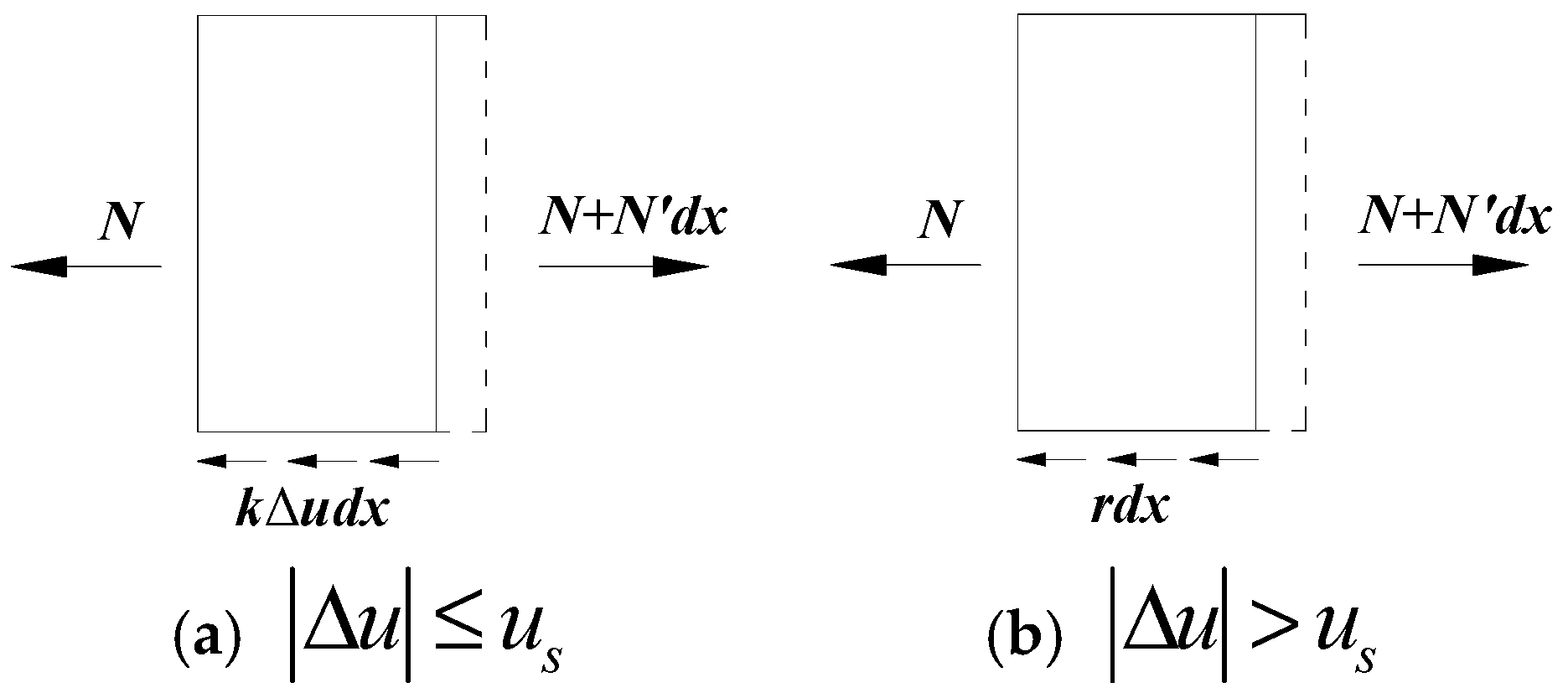
Taking a small length of rail segment dx, under the temperature variation condition, the longitudinal force of the rail microbody is shown in Figure 2.
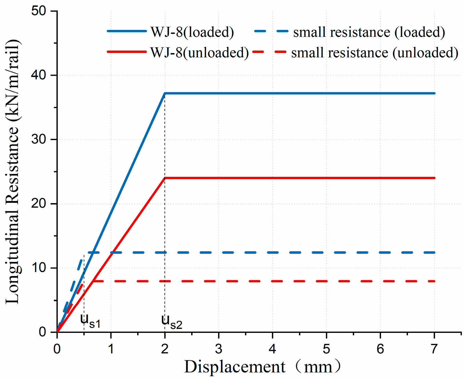
In light of the obvious nonlinear characteristics of longitudinal resistance between CWRs and bridge (shown in Figure 3), the basic equations of rail stress and displacement can be divided into the following two conditions.
I. | Δ u | u s (the longitudinal resistance is in the linear zone).
The equilibrium equation of rail segment dx can be expressed as follows:
N + N + N d x k Δ u d x = 0
(a) For rails located on the subgrade
Δ u = u
Equation (1) can be derived as:
E A u + k u = 0
The general solution of the displacement and the additional force can be obtained as follows:
u ( x ) = B i e λ x + C i e λ x
N ( x ) = E A ( λ B i e λ x λ C i e λ x α Δ t )
where u is the longitudinal displacement of rail; ∆ is the longitudinal displacement of the bridge; the relative displacement ∆u = u − ∆; uS is the critical point of the displacement in the resistance model; N is the additional longitudinal force of the rail; E is the elastic modulus of the rail; A is the cross-sectional area of the rail; k is the stiffness coefficient of the springs; and λ = (k/EA)1/2.
(b) For rails located on the bridge
Equation (3) can be derived as:
E A u + k ( u Δ ) = 0
The general solution of the displacement and the additional force can be obtained as follows:
u ( x ) = B i e λ x + C i e λ x + α 0 Δ T x
N ( x ) = E A ( λ B i e λ x λ C i e λ x + α 0 Δ T α Δ t )
II. | Δ u | > u s (the longitudinal resistance is in the plastic zone and the value is constant).
The equilibrium equation of rail segment dx can be expressed as follows:
N + N + N d x r d x = 0
(a) For rails located on the subgrade
Equation (1) can be derived as:
E A u ± r = 0
The general solution of the displacement and the additional force can be obtained as follows:
u ( x ) = ± p x 2 + B i x + C
N ( x ) = E A ( ± 2 p x + B i α Δ t )
where r is the constant of resistance and p = r/2EA.
(b) For rails located on the bridge
Equation (3) can be derived as:
E A u ± r = 0
The general solution of the displacement and the additional force can be obtained as follows:
u ( x ) = ± p x 2 + B i x + C i + α 0 Δ T x
N ( x ) = E A ( ± 2 p x + B i + α 0 Δ T α Δ t )
For the above analysis, the rail tensile stress is considered as positive and compressive stress as negative, whilst the rise of temperature is defined as positive. The fixed end of the bridge is set as the coordinate origin and the rightward x-axis is defined as positive. The beam displacement ∆, the rail displacement u and the relative displacement (u − ∆) are all regarded as positive when rightward.

3. Project Introduction and Fine Element Model

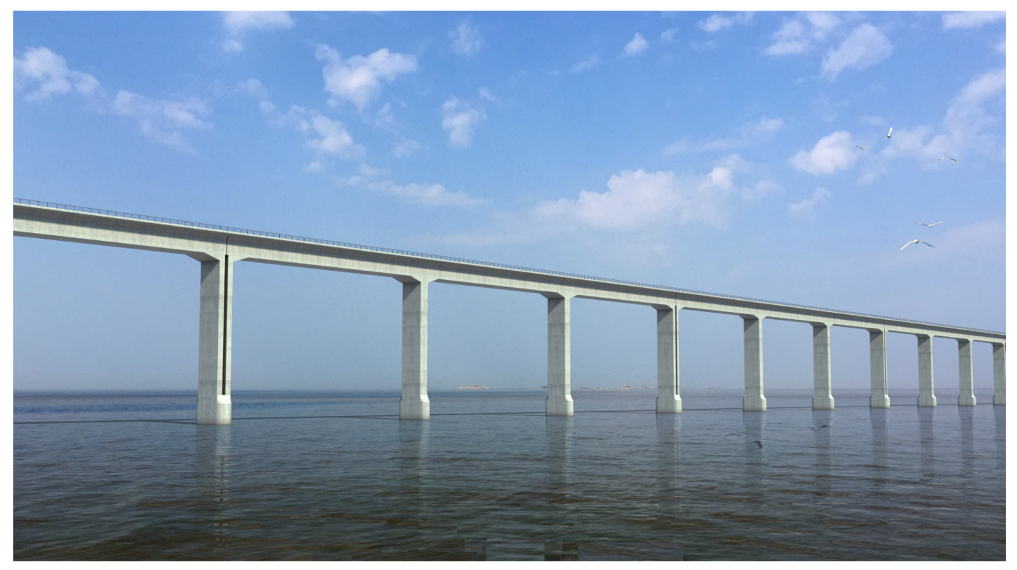
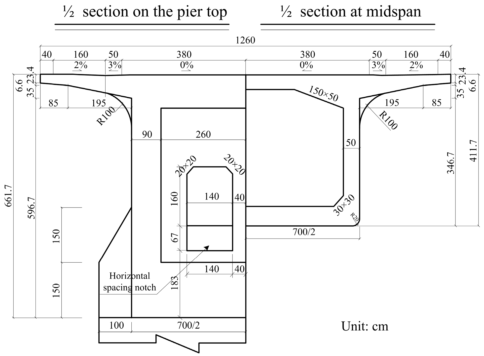
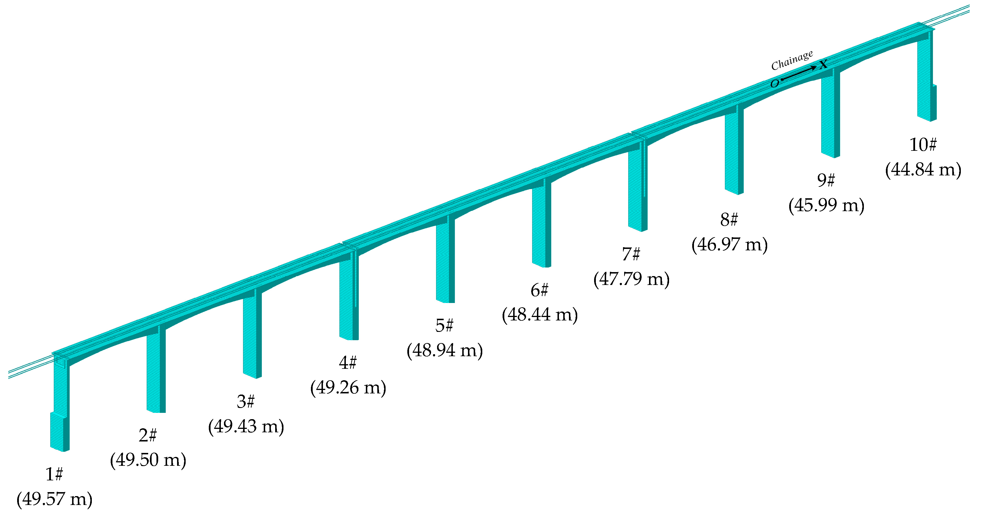
The approach bridge of Quanzhou Bay Bridge in the newly-built Fuzhou–Xiamen HSR utilizes multiple 3 × 70 m integral rigid-frame bridges. With no bearings throughout the whole bridge, the side piers and middle piers are consolidated with the main girder to form an integral rigid structure. The main girder of the bridge is made of a prestressed concrete box beam with a width of 12.6 m, as shown in Figure 4 and Figure 5. With heights of 44–50 m, the middle piers use solid or hollow rectangle piers, whilst the side piers use thin-wall piers. The side piers, which are located at the junction of two adjacent bridges, share the same foundation. In the calculation, the stiffness of piers is simulated according to the actual stiffness, taking the influence of pile foundations on the stiffness of piers into account. In order to eliminate the influence of boundary conditions on the calculation results, three identical integral rigid-frame integral bridges were built in the more accurate calculation result model, as shown in Figure 6 and Figure 7.
The newly-built Fuzhou–Xiamen HSR was designed as a passenger-dedicated line, with a design speed of 350 km/h. China Railway Track System (CRTS) I double-block ballastless tracks were adopted for this HSR line, with spacings of 5.0 m between lines. The line utilizes 60 kg/m rails, WJ-8 fasteners and SK-2 double block sleepers. The sleepers were prefabricated in a factory and laid in-situ, with spacings of 650 mm. The slab bed of the track was cast-in-place with C40 reinforced concrete.
With regard to the laying mode of each track layer, the model consists of three layers: ① rail; ② track slab plate; ③ base plate and beam body. In order to eliminate the influence of boundary conditions and simplify the modeling work as much as possible, the calculation is based on three integral rigid-frame bridges. The calculation model is shown in the Figure 6 and Figure 7; the main properties of the track and the bridge are listed in Table 1.
The key for establishing the analysis model of the CRTS type-I double-block ballastless track and the integral rigid-frame bridge system consists in the accurate simulation of the connections between each layer. The connections between layers are simulated by setting appropriate longitudinal, vertical and lateral linear /nonlinear spring elements. The connection constraint parameters and their corresponding values are specifically provided in the Table 2.
Several large-scale finite element (FE) software programs, such as ANSYS, ABAQUS and MIDAS, are widely adopted to study the track–bridge interaction of railway bridges ([4,11,12,13,14,16,17,18,19,20,25,26,27,28,29]). In [28], an analysis comparing such software with the calculating examples in UIC 774-3 was carried out and the analysis results verified the high precision of FE software.
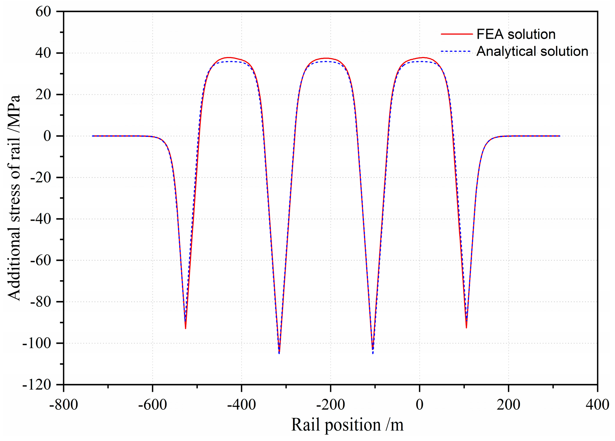
For the integral rigid-frame bridge, the analytical solution results based on differential equations and FE analysis results were compared. Figure 8 shows the additional force of the rail due to the temperature change of the bridge according to FEA and the analytical solution. This confirms that the FE calculation results are in good agreement with the theoretical solution.

4. Analysis of Additional Longitudinal Forces

4.1. Additional Expansion Force

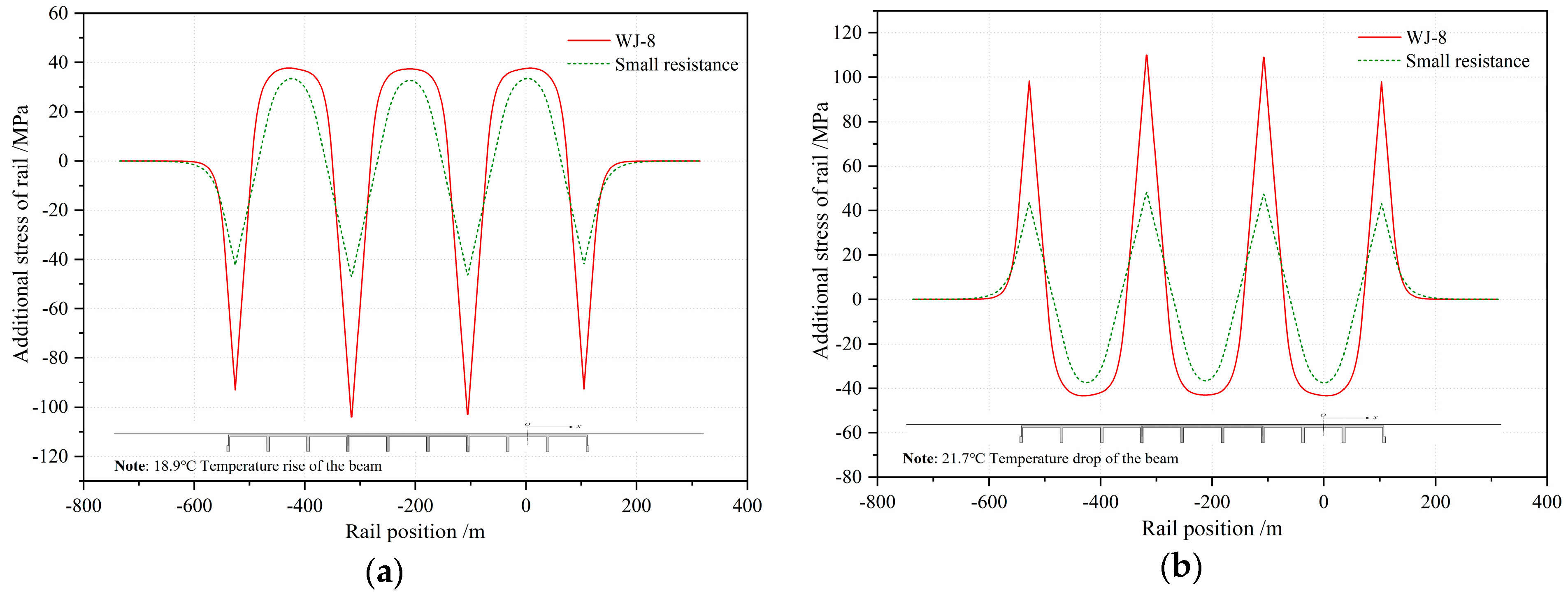
The additional expansion force is an essential part of the additional forces of CWRs and accounts for a large proportion of them [27,28]. Generally, in prior studies, only the bridge temperature rising or dropping is calculated, without considering the alternating changes of temperature [9,29]. In accordance with the temperature specified in the Chinese code [30] and results obtained by field survey, and since the temperature in the bridge closure period is 20 °C, the calculation results for load cases in which the bridge temperature rose by 18.9 °C and dropped by 21.7 °C were calculated and are shown in the Table 3.
From Figure 9 it is obvious that the maximum additional expansion stress of rails occurs at the beam ends of the middle integral rigid-frame bridge. When the bridge’s temperature rises, rails in the middle part of the rigid-frame bridge are subjected to tension, while the rails at the beam ends are subjected to higher pressure. When the temperature drops, the regularity is reversed. In addition, the additional expansion stress of rails is closely related to the resistance of the line. If the bridge temperature rises 18.9 °C or drops 21.7 °C, the maximum compressive/tensile additional stress of the rails is −103 MPa/109 MPa, while the maximum compressive/tensile additional stress of the rails after adopting small resistance fasteners decreases to −46.9 MPa/48.1 MPa.

4.2. Additional Bending Force

In the calculation of additional bending force, the load case of a moving train can be simplified to apply a uniform load on the whole length of the bridge [29,30]. The ZK live load (equivalent to the 0.8UIC live load), which is the standard live load for HSR bridges in the Chinese Code TB-10621-2014 [31], was adopted in the calculation of the additional bending force, as shown in Figure 10. Usually, the static live load is adopted, without considering the impact effect of passing trains.
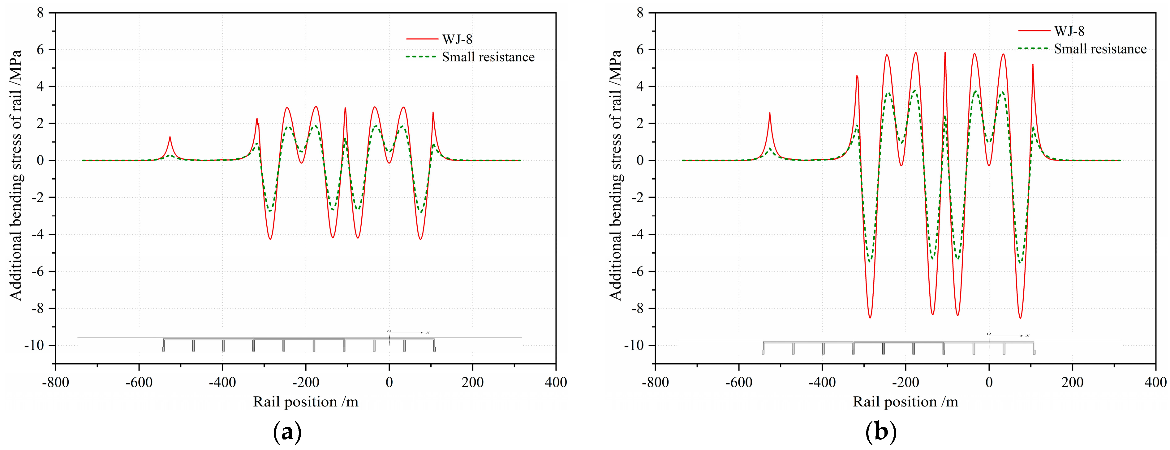
To get close to the actual operation conditions of the two-line high-speed railway, the additional bending forces under both single-line trains and double-line trains were calculated and analyzed. In the calculation, the ZK live load (equivalent to the 0.8UIC live load) was loaded on the two integral rigid-frame bridges (from pier 4 to pier 10).
Similarly to the common simply supported box-girder and continuous box-girder HSR bridges, the additional bending stress of the rails located in the integral rigid-frame bridge was very small, with an absolute value less than 4.3 MPa under the action of a single-line train and less than 8.5 MPa under double-line trains (as shown in Figure 11). The reason is that the vertical stiffness of the integral rigid-frame bridge is relatively large and the bending deformation of the beam caused by the vertical load is very small, which consequently gives rise to the very small longitudinal displacement along the neutral axis of the beam body. Furthermore, the additional bending stress of the rail showed a decreasing trend after adopting the small resistance fasteners, with a maximum stress (absolute value) of 2.83 MPa under a single-line train and 5.6 MPa under double-line trains.

4.3. Additional Braking Force

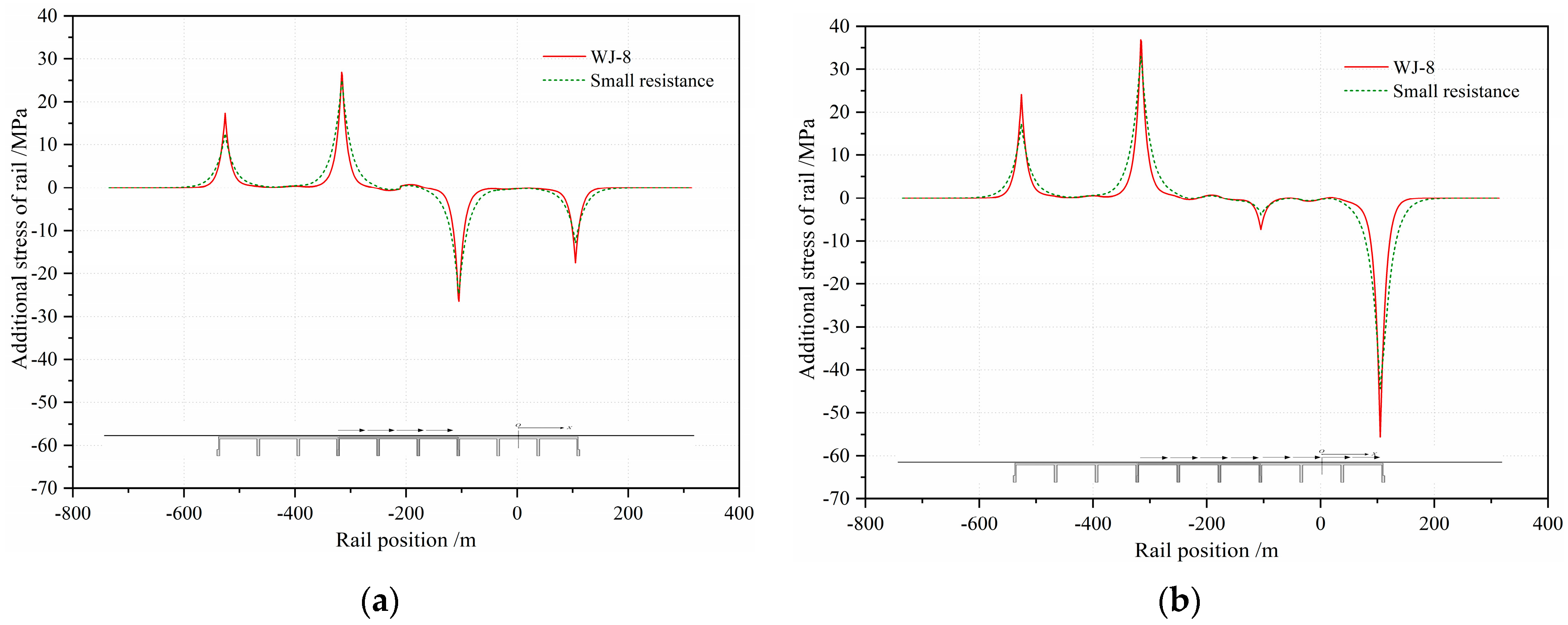
The calculating models of the live load were the same as the model stated in Section 4.2, and the braking coefficient of the HSR train was set as 0.164 [29,30]. The braking load can be calculated as q = 0.164 × qzk =0.164 × 64 kN/m = 10.5 kN/m. In the calculation, the braking load was only applied on one single line, as there is little possibility of trains braking on both lines of the bridge at the same time. The rightward braking loads of the HSTs were regarded as the positive direction, and vice versa. Furthermore, based on the consideration that Chinese high-speed trains basically consist of either 8 or 16 carriages, with a total length of about 200 m or 400 m, two calculation conditions with different loading positions were adopted herein: condition I: the braking load is positioned over the middle integral bridge (from pier 4 to pier 7); and condition II: the braking load is positioned over the middle and right integral bridges (from pier 4 to pier 10).
When the train braked in the middle bridge (condition I), the maximum additional braking stress of the rail occurred at the two beam ends of the middle rigid-frame bridge, with the value of −26.5 MPa/26.9 MPa, as shown in Figure 12. However, the maximum additional stress of condition II appeared at the ends of the load position (piers 4 and 10), with the value of −55.6 MPa/36.8 MPa. After adopting the small resistance fasteners, the maximum additional braking stress of the rail decreased by 4.0%/3.8% under condition I and by 10.3%/19.6% under condition II.
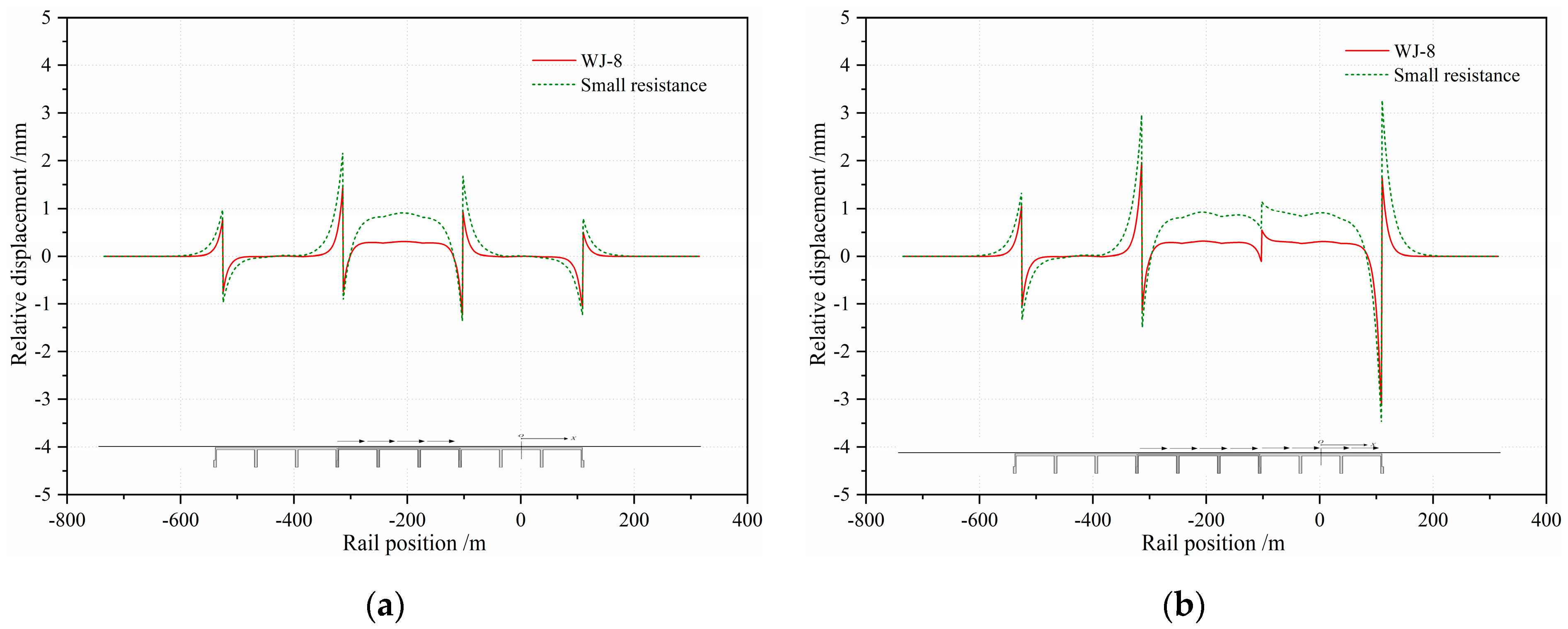
With regard to the relative displacement between the rail and the beam, UIC code 774−3R [8] clearly requires that the relative displacement under the action of braking force should not exceed 5 mm. As shown in Figure 13, the relative displacements under condition I were less than those for condition II. Under condition II, the maximum relative displacement between the rail and the beam was 3.11 mm when WJ-8 fasteners were adopted. After small resistance fasteners were adopted, the relevant maximum value was 3.48, with an increase of 11.9%.

4.4. Rail-Broken Gap

Long welded rails are subjected to pressure when they are heated and tensile when they are cooled. If the rail temperature is too low in the winter season, long welded rails may fracture [1,2]. Once a rail fractures, the internal force of the rail near the fracture position is immediately released and a broken gap forms.
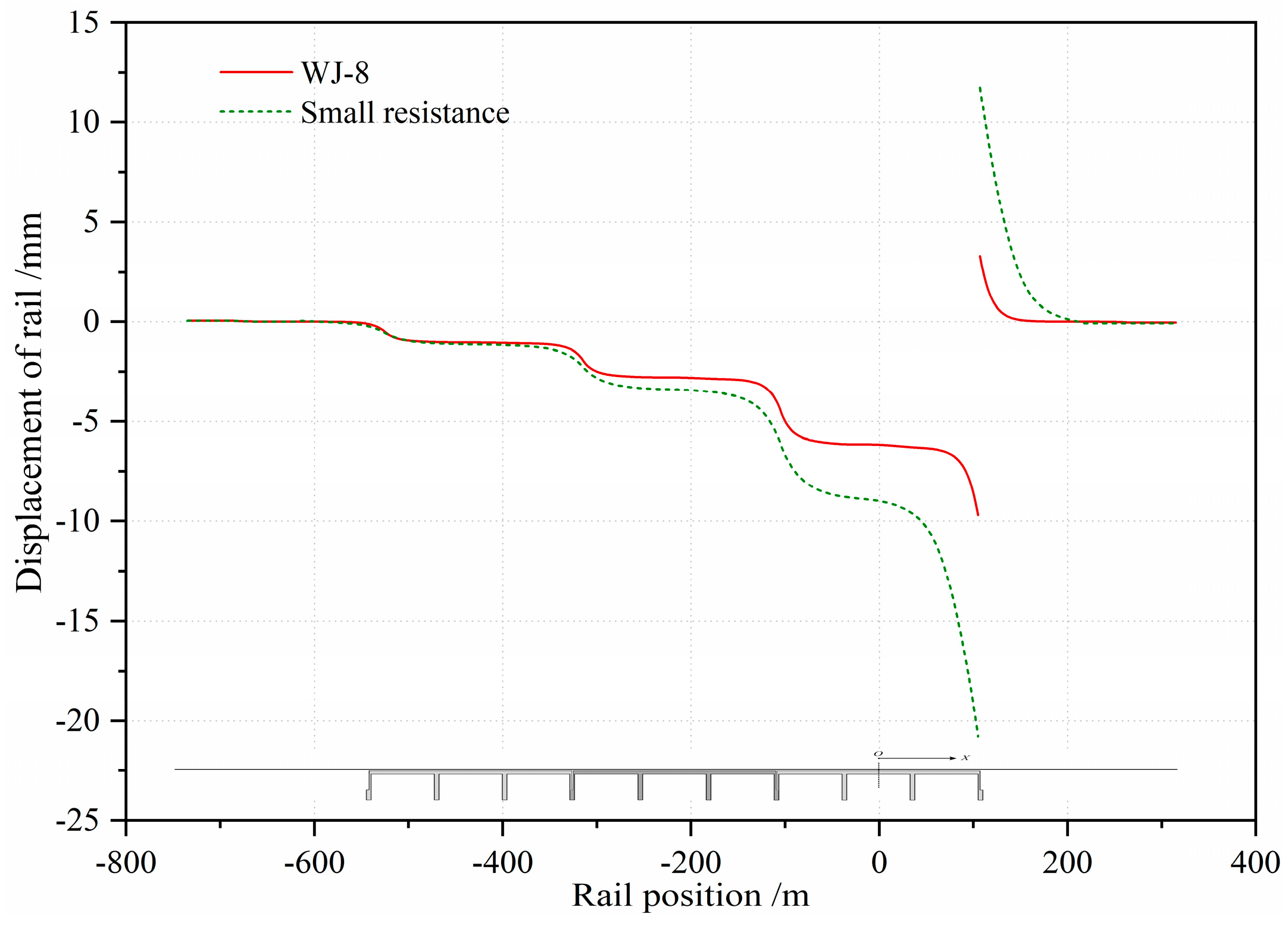
Figure 14 shows that the rail stress decreases to 0 MPa at the position of the rail fracture and the rail stress around the broken position also obviously decreases. As shown in Figure 15, the broken gap increases greatly if small resistance fasteners are adopted.
As a broken gap affects the safety and comfort of the passing train, the value of a rail broken gap is clearly specified in relative codes [30]. The broken gap of the rail can be calculated by finite element analysis or by the following equation:
λ = E F ( α Δ T d max ) 2 r
where λ is the rail gap after the rail broken; ∆Tdmax is the maximum rail temperature decrease; E is the Young’s modulus of the rail; F is the cross-sectional area of the rail; α is the thermal expansion coefficient; and r is the longitudinal resistance.
The calculated results of the broken gap with the adoption of two different kinds of fasteners are shown in Table 4. The calculation results of the broken gap of a CWR by the finite element analysis method are in good agreement with those of Equation (16).

5. Parameters Study

5.1. Longitudinal Resistance

The longitudinal resistance of fasteners affects the additional stress of ballastless rails directly, while the models and values of longitudinal resistance specified in different codes differ greatly from each other [7,8,30]. The elastic-plastic model specified in UIC code 774-3R is now widely adopted around the world. Developed from a large number of model experiments and field tests, the calculating models and values of the longitudinal resistances of WJ-8 fasteners and small resistance fasteners on the ballast and ballastless tracks are included in the Chinese code TB 10015-2012 [30].
In Section 4 of this paper, the influence of the fastener resistance on various additional stresses was compared when describing the stress characteristics of the integral rigid-frame bridge, as shown in Figure 8, Figure 9, Figure 10, Figure 11, Figure 12, Figure 13, Figure 14 and Figure 15. In order to show the influence of the fastener resistance on the TBI calculation results, various additional stresses are listed in Table 5.
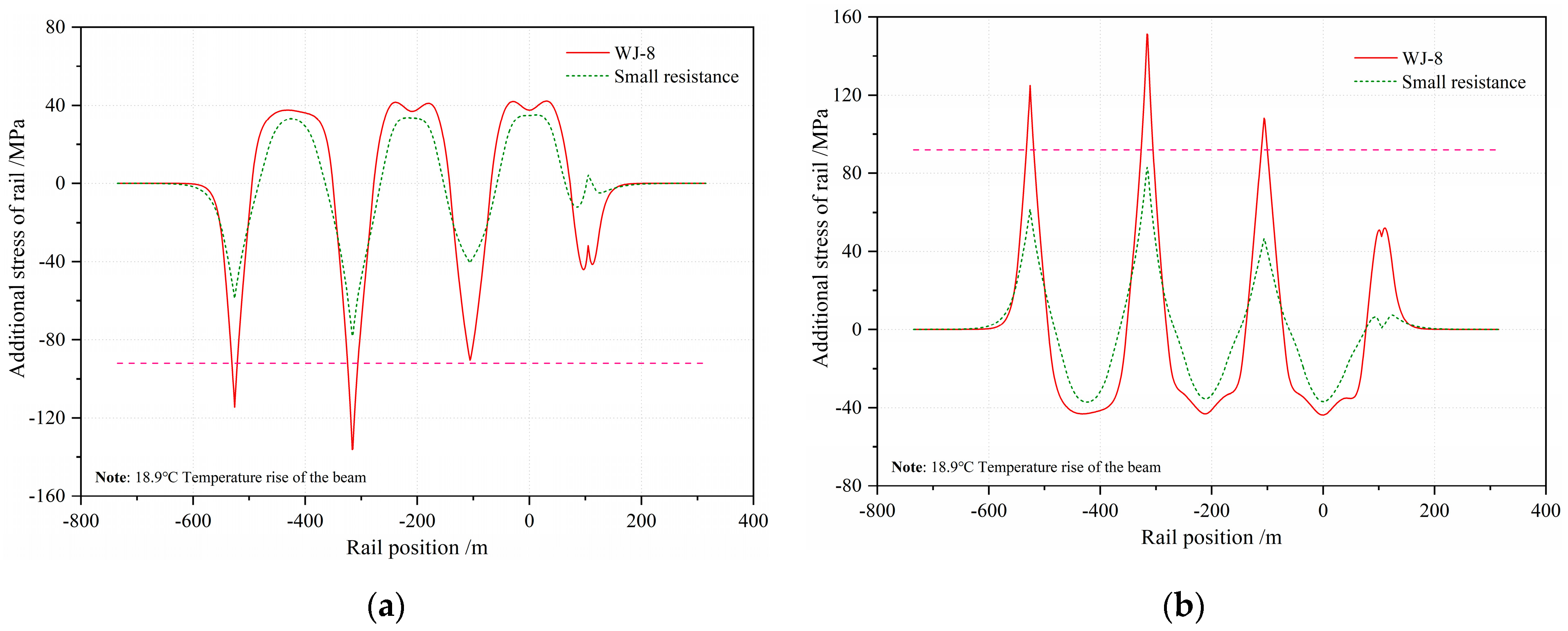
Generally, when the longitudinal resistance is reduced, the additional expansion stress of the rail most obviously decreases (by about 55%), followed by the additional braking stress (by more than 10% under condition II), as shown in Figure 16. According to UIC 774-3R, the additional stress of the rail is required to be less than −92 MPa/92 MPa [8]. However, in the Chinese code TB 10015-2012, the total stress of the rail has a limitation while the additional stress has no specific requirements. Table 5 indicates that the total additional rail stress exceeds the limit values of the current relevant codes when the WJ-8 fastener is adopted. Therefore, for this integral rigid-frame bridge with a span of 3 × 70 m, small resistance fasteners are suggested to be selected in order to avoid the arrangement of the rail expansion joint. With the decrease of the fastener resistance, the rail broken gap increases greatly, by 199.2%.

5.2. Influence of the Arrangement Schemes of Adjacent Bridges

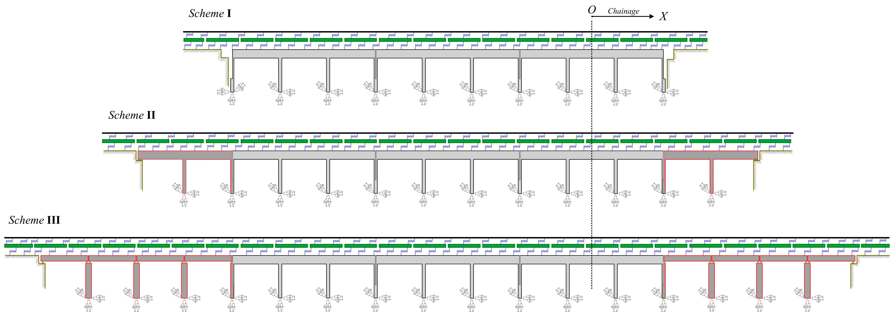
Different arrangement schemes of the adjacent bridges have a great influence on the additional forces of rails, since the expansion length of the bridge inevitably changes. As a consequence, three representative calculation models, as shown in Figure 17, are described in this study in order to discuss and explore the most reasonable arrangement scheme of the adjacent span.
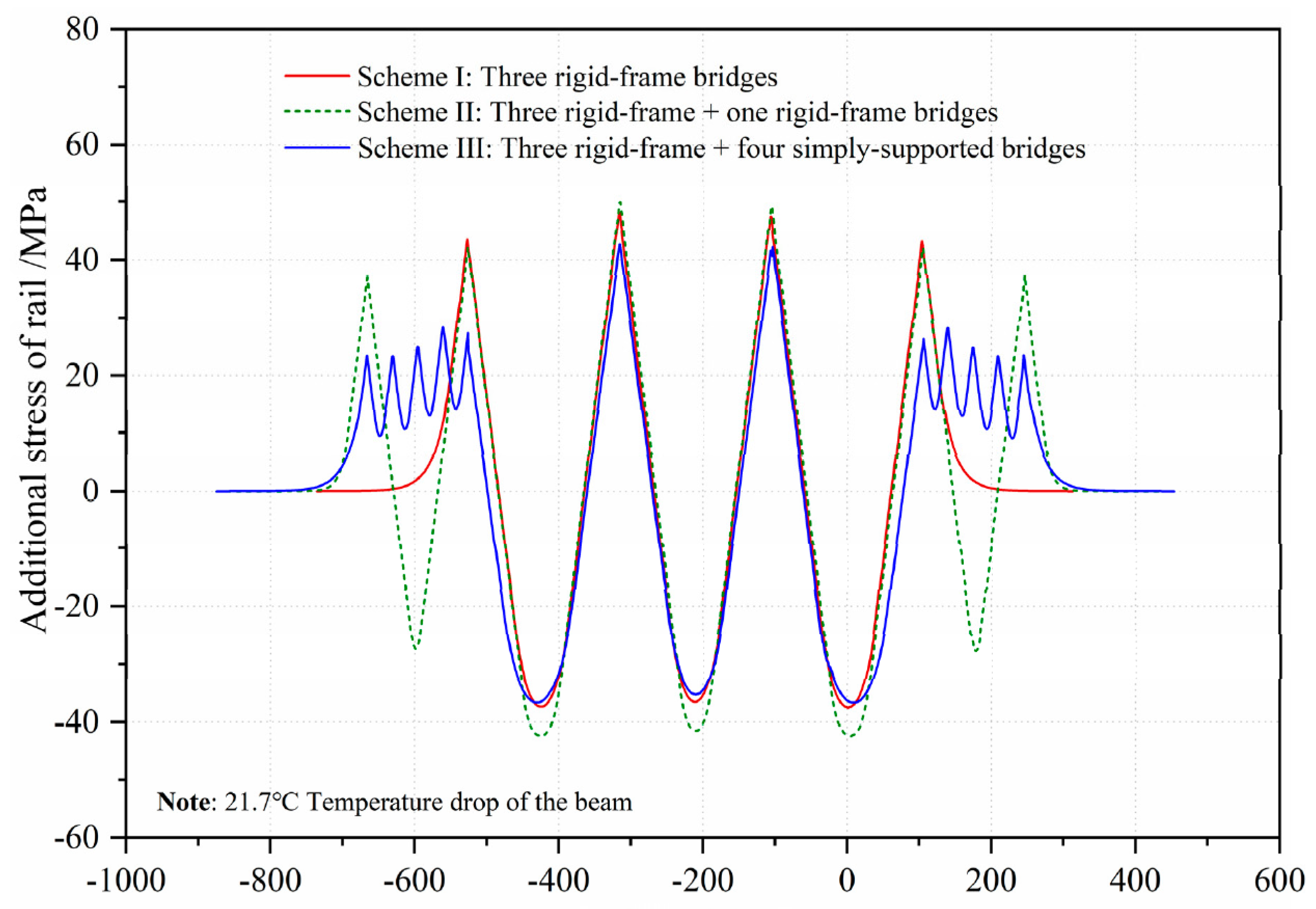
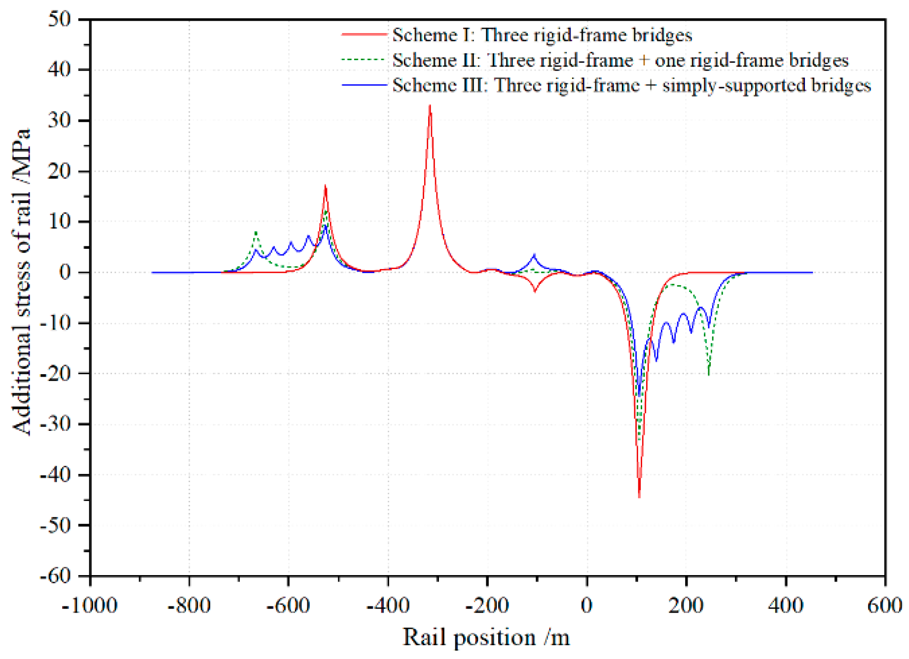
Under the effect of the beam temperature dropping, which is shown in Figure 18, the minimum/maximum stress of the rail on the middle integral rigid-frame bridge can be represented as: scheme III (−37.0 MPa/45.1 MPa) < scheme I (−37.6 MPa/48.1 MPa) < scheme II (−42.4 MPa/49.9 MPa). Under the action of the train braking, as shown in Figure 19 (condition II), the minimum /maximum stress of the rail can be represented as: scheme III (−33.0 MPa/19.3 MPa) < scheme II (−33.0 MPa/33.1 MPa) < scheme I (−44.5.0 MPa/33.0 MPa). As a whole, scheme III, adopting four simply supported bridges as adjacent bridges, can be deemed to be the best choice to reduce the additional forces on CWRs in this novel integral rigid-frame bridge.

5.3. Influence of the Pier Stiffness

For the integral rigid-frame bridge, the pier stiffness has a significant influence on the track–bridge interaction. If the pier stiffness is too large, the deformation of the beam is restrained. On the contrary, if the stiffness of the pier is too small, the relative displacement between the beam and track under the action of the braking force increases greatly and the total additional force of the rail exceeds the standard limit value.
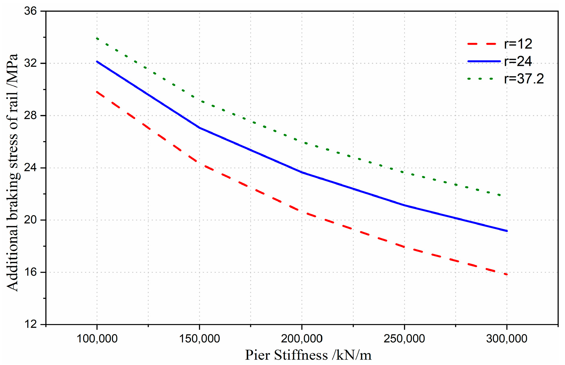
As shown in Figure 20 and Figure 21, the calculation results indicate that the additional braking stress and total additional stress of the rail increase with the decrease of pier stiffness. With the increase of the longitudinal resistance between the CWR and the bridge, the limited value of the minimum pier stiffness increases accordingly. To meet the requirement that the total additional stress of the rail should be less than 92 MPa, the minimum threshold value of the pier stiffness should be about 0.52 × 10⁵ kN/m if the resistance is 12 kN/m/rail, and the minimum threshold value of the pier stiffness should be nearly 1.0 × 10⁵ kN/m if the longitudinal resistance between rail and beam is 37.2 kN/m/rail.

6. Conclusions

In this paper, a series of refined FE integrative models were proposed to investigate the characteristics of additional forces on CWRs of a novel HSR bridge structure system. The representative additional forces were illustrated and discussed in detail. Specifically, the influences of different design parameters, such as suitable types of rail fasteners, optimal layout schemes of adjacent bridges and the reasonable stiffness of piers, were studied. Several major conclusions can be drawn from this work as follows:
(1)
The additional expansion force accounts for the largest proportion of the additional force of integral rigid-frame bridges, followed by the additional braking force. Due to the large vertical stiffness of this kind of bridge, the additional bending force is small and can be ignored.
(2)
Through comparative studies of two types of fasteners with different longitudinal resistances, this study verified that a decrease of resistance weakens the various additional forces caused by the interaction between track and bridge; notably, the additional expansion stress of the rail decreased by 55%. However, the rail broken gap increases greatly.
(3)
For this 3 × 70 m integral rigid-frame bridge, adopting the widely-used WJ-8 fasteners, the total additional stresses reached −143.1 MPa and 151.7 MPa, which both exceed the standard limit in the UIC code. If no rail expansion joints are arranged, small resistance fasteners are suggested to be adopted for this new HSR line to reduce the additional stress of the CWR.
(4)
By adopting 4 × 32 m simply supported beams as the adjacent span arrangement scheme, the additional expansion stress and the additional braking stress of the rails in the integral rigid-frame bridge were less than the corresponding stresses in other schemes.
(5)
The minimum threshold value of the pier stiffness for integral rigid-frame bridges is closely related to the longitudinal resistance of HSR lines. With an increase of the longitudinal resistance between the CWR and the bridge, the minimum threshold value of the pier stiffness increases accordingly.

Author Contributions

Conceptualization, W.L. and G.D.; methodology, S.R.; formal analysis, H.L.; validation, W.L., S.R. and H.L.; data curation, H.L.; writing—original draft preparation, W.L.; writing—editing, H.L.; writing—review, G.D.; project administration, D.W. and B.W. All authors have contributed to the whole paper. All authors have read and agreed to the published version of the manuscript.

Funding

This research was funded by the National Natural Science Foundation of China (Grant No. 51708560); the Natural Science Foundation of Hunan Province (Grant No. 2018JJ3672); the Science and Technology Research and Development Program of China Railway Corporation (Grant No. K2018G017); and the Science and Technology Research and Development Program of China Railway Siyuan Survey and Design Institute Group Co., Ltd. (Grant No. 2018K002).

Institutional Review Board Statement

Not applicable.

Informed Consent Statement

Not applicable.

Data Availability Statement

Not applicable.

Acknowledgments

The authors would like to express their gratitude for the support from China Railway Siyuan Survey and Design Group Co., Ltd. and China Southeast Coast Railway Group (Fujian) Co., Ltd. The second author would also like to acknowledge the support of the Fundamental Research Funds for the Central Universities of Central South University (2019zzts627).

Conflicts of Interest

The authors declare no conflict of interest in this work.

References

  1. Esveld, L.C. Modern Railway Track, 2nd ed.; MRT Production: Kâğıthane/İstanbul, Turkey, 2001. [Google Scholar]
  2. Guang, Z.Y. Railway Continuous Welded Rail, 4th ed.; China Railway Publishing House: Beijing, China, 2005. (In Chinese) [Google Scholar]
  3. Frýba, L. Dynamics of Railway Bridges; Thomas Telford Ltd.: London, UK, 1996. [Google Scholar]
  4. Gao, L. Research and Application of Key Technologies of Continuous Welded Rails on High-Speed Railway; China Railway Publishing House: Beijing, China, 2012. (In Chinese) [Google Scholar]
  5. Yang, G.T.; Bradford, M.A. Thermal-induced buckling and postbuckling analysis of continuous railway tracks. Int. J. Solids Struct. 2016, 97, 637–649. [Google Scholar] [CrossRef]
  6. Frýba, L. Quasi-static distribution of braking and starting forces in rail and bridges. Rail Int. 1974, 22, 698–716. [Google Scholar]
  7. German Standard DS899/59. Special Procedures on Railway Shinkansen Bridge; Bridge Institute of Railway Bridge Authority: Berlin, Germany, 1985. (In German) [Google Scholar]
  8. International Union of Railways. 774-3R. In Track-Bridge Interaction Recommendations for Calculations, 2nd ed.; UIC International Union of Railways: Paris, France, 2001. [Google Scholar]
  9. Ruge, P.; Birk, C. Longitudinal forces in continuously welded rails on bridge decks due to nonlinear track-bridge interaction. Comput. Struct. 2007, 85, 458–475. [Google Scholar] [CrossRef]
  10. Ruge, P.; Widarda, D.R.; Schmälzlin, G.; Bagayoko, L. Longitudinal track-bridge interaction due to sudden change of coupling interface. Comput. Struct. 2009, 87, 47–58. [Google Scholar] [CrossRef]
  11. Calçada, R.; Delgado, R.; e Matos, A.C.; Goicolea, J.M.; Gabaldon, F. Track-Bridge Interaction on High-Speed Railways: Selected and Revised Papers from the Workshop on Track-Bridge Interaction on High-Speed Railways; CRC Press: Porto, Portugal, 2008. [Google Scholar]
  12. Zhang, J.; Wu, D.J.; Li, Q. Loading-history-based track-bridge interaction analysis with experimental fastener resistance. Eng. Struct. 2015, 83, 62–73. [Google Scholar] [CrossRef]
  13. Yang, S.C.; Jang, S.Y. Track-bridge interaction analysis using interface elements adaptive to various loading case. J. Bridge Eng. 2016, 21, 04016056. [Google Scholar] [CrossRef]
  14. Dai, G.L.; Ge, H.; Liu, W.S.; Chen, Y.F. Interaction analysis of continuous slab track (CST) on long-span continuous high-speed rail bridges. Struct. Eng. Mech. 2017, 63, 713–723. [Google Scholar]
  15. Choi, H.S.; Lee, K.C.; Lee, S.C.; Lee, J. Interaction analysis of sliding slab track on railway bridge considering behavior of end-supporting anchors. Int. J. Steel Struct. 2019, 19, 1939–1950. [Google Scholar] [CrossRef]
  16. Cho, S.; Lee, K.C.; Jang, S.Y.; Lee, I.; Chung, W. Sequential track-bridge interaction analysis of quick-hardening track on bridge considering interlayer friction. Appl. Sci. 2020, 10, 5066. [Google Scholar] [CrossRef]
  17. Chen, R.; Wang, P.; Wei, X.K. Track-bridge longitudinal interaction of continuous welded rails on arch bridge. Math. Probl. Eng. 2013, 2013, 1–8. [Google Scholar] [CrossRef] [Green Version]
  18. Liu, W.S.; Dai, G.L.; Yu, Z.W.; Chen, Y.F.; He, X.H. Interaction between continuous welded rail and long-span steel truss arch bridge of a high-speed railway under seismic action. Struct. Infrastruct. Eng. 2018, 14, 1051–1064. [Google Scholar] [CrossRef]
  19. Cai, X.P.; Liu, W.L.; Xie, K.Z.; Zhu, W.J.; Tan, X.Y.; Gao, Y.J. Layout optimization of rail expansion joint on long-span cable-stayed bridge for high-speed railway. Adv. Civ. Eng. 2020, 2020. [Google Scholar]
  20. Yan, B.; Zhang, G.X.; Han, Z.S.; Lou, P. Longitudinal force of continuously welded rail on suspension bridge with length exceeding 1000 m. Struct. Eng. Int. 2019, 29, 390–395. [Google Scholar] [CrossRef]
  21. Marx, S.; Seidl, G. Integral railway bridges in Germany. Struct. Eng. Int. 2011, 21, 332–340. [Google Scholar] [CrossRef]
  22. Kang, C.J.; Schneider, S.; Wenner, M.; Marx, S. Development of design and construction of high-speed railway bridges in Germany. Eng. Struct. 2018, 163, 184–196. [Google Scholar] [CrossRef]
  23. Zhu, L.B. Application of no support continuous rigid-framed system in Line 6. Superv. Test Cost Constr. 2017, 10, 38–41. (In Chinese) [Google Scholar]
  24. Wen, W.Q.; Wang, D.Z.; Wu, B.; Ling, Y.F.; Kou, Y.C. Design of integral rigid-frame bridge without bearings on high-speed railway. Bridge Constr. 2020, 50, 86–91. (In Chinese) [Google Scholar]
  25. Xiong, Z.W.; Xie, K.Z.; Liu, H.; Wang, P. Influence of train braking on relative displacement between girder and rail of continuous welded rail upon rigid-frame bridge. Railw. Stand. Des. 2013, 57, 10–14. (In Chinese) [Google Scholar]
  26. Liu, H.; Ren, J.J.; Liu, Y.; Liu, X.Y. Study on dynamic characteristics of continuously welded rail track on rigid bridge with long steep grade. Railw. Stand. Des. 2015, 59, 5–8. (In Chinese) [Google Scholar]
  27. Dai, G.L.; Liu, W.S. Applicability of small resistance fastener on long-span continuous bridges of high-speed railway. J. Cent. South Univ. 2013, 20, 1426–1433. [Google Scholar] [CrossRef]
  28. Liu, W.S.; Dai, G.L.; He, X.H. Sensitive factors research for track-bridge interaction of a long-span X-style steel-box arch bridge on high-speed railway. J. Cent. South Univ. 2013, 20, 3314–3323. [Google Scholar] [CrossRef]
  29. Qing-yuan, X. Static and Dynamic 3D Finite Element Analysis of Additional Longitudinal Forces Transmission between CWR and High-Speed Railway Bridges [D]; Central South University: Changsha, China, 2005. (In Chinese) [Google Scholar]
  30. Chinese National Standard, TB10015-2012. Code for Design of Railway Continuous Welded Rail; China Railway Publishing House: Beijing, China, 2012. (In Chinese) [Google Scholar]
  31. Chinese National Standard, TB-10621-2014. Code for Design of High Speed Railway; China Railway Publishing House: Beijing, China, 2016. (In Chinese) [Google Scholar]
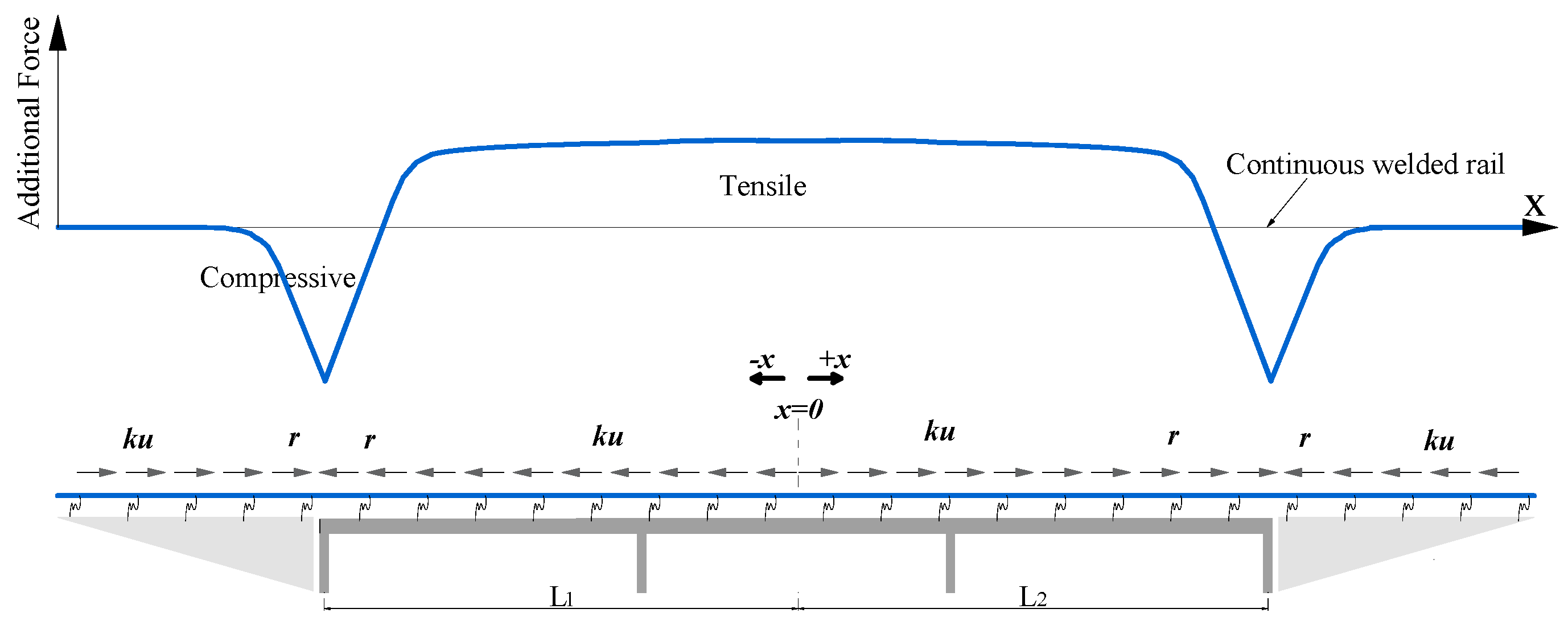
Figure 1. Basic mechanism of longitudinal additional force.
Applsci 11 00922 g001
Figure 2. Longitudinal mechanical properties of rail microbody (under temperature variation).
Applsci 11 00922 g002
Figure 3. Bilinear model of longitudinal resistance.
Applsci 11 00922 g003
Figure 4. Design rendering of the integral rigid-frame bridge of the Fuzhou–Xiamen high-speed railway (HSR).
Applsci 11 00922 g004
Figure 5. Cross-section of integral rigid-frame bridge.
Applsci 11 00922 g005
Figure 6. Sketch drawing of the calculating model of track–bridge interaction for an integral rigid-frame bridge.
Applsci 11 00922 g006
Figure 7. Integrated finite element (FE) model for track–bridge analysis.
Applsci 11 00922 g007
Figure 8. Comparison of the additional force of the rail according to finite element analysis (FEA) and the analytical solution.
Applsci 11 00922 g008
Figure 9. Additional expansion force of rails under bridge temperature variation: (a) temperature rising; (b) temperature dropping.
Applsci 11 00922 g009
Figure 10. Graphical representation of the ZK live load.
Applsci 11 00922 g010
Figure 11. Additional bending force of rails: (a) under a single-line train; (b) under double-line trains.
Applsci 11 00922 g011
Figure 12. Additional braking force of rails under different braking conditions: (a) condition I; (b) condition II.
Applsci 11 00922 g012
Figure 13. Relative displacement between rail and beam under different conditions: (a) condition I; (b) condition II.
Applsci 11 00922 g013
Figure 14. Additional stresses of the rail before and after rail fracture.
Applsci 11 00922 g014
Figure 15. Displacements of the rail in the case of rail fracture.
Applsci 11 00922 g015
Figure 16. Total additional stress of the rail: (a) under rising temperature; (b) under falling temperature.
Applsci 11 00922 g016
Figure 17. Three calculation models of the adjacent bridges with different arrangement schemes.
Applsci 11 00922 g017
Figure 18. Additional expansion forces of the rail for three different schemes.
Applsci 11 00922 g018
Figure 19. Additional braking forces of the rail for three different schemes.
Applsci 11 00922 g019
Figure 20. Additional braking stress of the rail under different pier stiffness.
Applsci 11 00922 g020
Figure 21. Total additional stress of the rail under different pier stiffness.
Applsci 11 00922 g021
Table 1. Main properties of the track and the bridge.
Structure LayerMaterialYoung’s ModulusThermal Expansion CoefficientPoisson’s RatioVolume Weight
RailU712.06 × 105 MPa1.18 × 10−50.378.5 kN/m3
Slab plateC403.40 × 104 MPa1.0 × 10−50.225 kN/m3
Base plateC403.40 × 104 MPa1.0 × 10−50.225 kN/m3
Bridge beamC503.55 × 104 MPa1.0 × 10−50.225 kN/m3
PierC503.55 × 104 MPa1.0 × 10−50.225 kN/m3
Table 2. Parameter values of constraints and connections.
Connection ConstraintSpring DirectionSpring TypeSpring Stiffness
Rail and track slab VerticalLinear spring25–35 kN/mm
LongitudinalNonlinear spring WJ-8(load) { r = 18.6 x , x 2.0 mm r = 37.2 , x > 2.0 mm
WJ-8(unload) { r = 12 x , x 2.0 mm r = 24 , x > 2.0 mm
Small(load) { r = 24.8 x , x 0.5 mm r = 12.4 , x > 0.5 mm
Small(unload) { r = 16 x , x 0.5 mm r = 8 , x > 0.5 mm
LateralLinear spring10 kN/mm
Track slab and bed slab
(geotextile cushion and groove)
VerticalLinear spring−1.0 × 10⁶ kN/mm
Longitudinal and lateralLinear spring1.0 × 108 kN/mm
Table 3. Temperature load cases.
AreaHighest Air Temperature/°CLowest Air Temperature/°CHighest Rail Temperature/°CLowest Rail
Temperature/°C
Note
Fuzhou41.7−1.761.7−1.7Code for Design of Railway CWR (TB10015-2012)
Quanzhou38.9−1.761.7−2.3Field survey(bridge location)
Table 4. Broken gap of the continuous welded rail.
FastenersDesign Stress-Free Rail Temperature/°CMaximum Temperature
Drop of the Rail/°C
Broken Gap /mmAllowable Gap
/mm
WJ-8 fastener30 ± 537.312.970
Small resistance fastener30 ± 537.338.670
Note: 37.3 °C = 35 °C − (−2.3 °C), where −2.3 °C is the lowest rail temperature listed in Table 3.
Table 5. Comparison of various additional stresses and strength checks with different fasteners.
SchemesAdditional Expansion Stress
of Rail
/MPa
Additional
Bending Stress
of Rail
/MPa
Additional
Braking Stress
of Rail
/MPa
Total
Additional Stress of Rail
/MPa
Gap
/mm
Min/MaxMin/MaxMin/MaxMin/MaxMin/MaxMin/MaxMax
WJ-8 fastener−103/109−4.3/2.9−8.5/5.9−26.5/26.9−55.6/36.8−143.1/151.712.9
Small resistance fastener−46.9/48.1−2.8/1.9−5.6/3.8−24.7/25.0−44.5/33.0−84.6/84.938.6
Limit/////−92/9270
Note: Positive stress is tensile stress and negative stress is compressive stress.
Publisher’s Note: MDPI stays neutral with regard to jurisdictional claims in published maps and institutional affiliations.