Article

Conceptual Design of the Combinable Legged Robot Bio-Inspired by Ants’ Structure

Department of Mechanical Engineering, Graduate School, Kyungpook National University, Bukgu, Daegu 41566, Korea
*
Author to whom correspondence should be addressed.
Appl. Sci. 2021, 11(4), 1379; https://doi.org/10.3390/app11041379
Submission received: 31 December 2020 / Revised: 29 January 2021 / Accepted: 29 January 2021 / Published: 3 February 2021
(This article belongs to the Special Issue Bio-Inspired Robot and Multirobot Systems)

Abstract

:
This study presents a new combinable multi-legged modular robot that mimics the structures of ants to expand the physical capabilities of the legged robot. To do this, the robot design is focused on exploring a fusion of two robotic platforms, modular and multi-legged, in which both the body frame and the legged structure are designed to be a rectangular prism and a 3-DoF sprawling-type articulated leg structure, respectively. By imitating ants’ claws, the hook-link structure of the robot as the coupling mechanism is proposed. This study includes the platform’s development, and the experimental work on the locomotion in both single and combined modes is carried out. The result of this study proves that mimicking ants’ structure in the proposed robots successfully enhances the capability of the conventional legged robot. It is feasible to use in a multi-robot system to realize ants’ super-organized behavior.

1. Introduction

In the last decade, there have been many research efforts in robot design that have promised more efficient and more reliable mechanisms than before [1,2,3,4]. However, it is not feasible for them to perform all the tasks required. Most of the robot designs are mainly focused on the application requirements. More research is needed in exploring innovative mechanisms to solve the limited physical capability of conventional robots.
In recent years, a variety of designs have been evolving in the field of biomimetic robots, which applies the characteristic of bio-systems to robotic systems [5]. This biomimetic design usually shows outstanding outcomes in innovating the physical capability of the robot. Andrada et al. proposed a climbing robot, “Rat-Nic”, that was inspired by the adaptability of rats on a slope [6]. Li et al. developed a bouncing robot “Grillo”, the ingenuity of which was based on the jumping of leafhoppers [7]. Song et al. created a hybrid leg structure for a quadruped robot that improved the load capacity of conventional multi-legged robots [8]. Liljeback et al. introduced a fire rescue snake-like robot, “Anna-Konda” [9]. Ahmad et al. demonstrated a new six-legged robot inspired by ant locomotion [10].
However, there is little research on robot design that is bio-inspired by the hybrid behaviors of animals like the multi-functional mode of ants. Ants are eusocial insects that favor a temporary mechanical combination for movement to improve the physical performance as a group in a given situation [11,12]. As shown in Figure 1, ants are not only able to behave like a modular multi-legged robot with an identical body structure, they are also capable of combining with each other using their claws. Therefore, the realization of the ants’ structure could possibly expand the robot’s capability.
Up to now, the previous research has generally focused on mimicking the walking motion of ants with a variety of walking gaits on uncertain terrain [1,13]. Although there are many types of research to implement the collaborative behavior of ants [5,14,15], robot structures that enable implementing physical capabilities like ant locomotion have not been realized yet. This is due to the difficulty in realizing a structure for a multi-leg robot that consists of the coupling mechanisms at the same time. This study focuses on the investigation into the physical combinable behavior of legged robots inspired by ants’ structure. For the realization of the multi-leg robot with the coupling mechanism, the structure of the proposed robot is simplified.
The objective of this research is to present the design and performance of the combinable multi-leg modular robot bio-inspired by ants’ leg locomotion and their claws. The details of the robot design are presented in Section 2. The control system of the proposed robot is described in Section 3. Basic locomotion in the experiment is explained in Section 4: the robot walking alone and in combined status. The results of the experimental data are tabulated and presented in Section 5. The results are discussed in Section 6.

2. Robot Design

This study aims to mimic the functionality of ants’ anatomy, but does not attempt to imitate the full anatomical structure of ants (i.e., the head, thorax, and abdomen). Ants employ their two front legs to connect to other objects and their four back legs for walking. From a functional point of view, the two front legs of real ants are replaced in this study by a pair of coupling mechanisms (using a hook-link structure) to connect with other identical robots [16]. The robot body frame in this study is considered as the center part (thorax) of the ants’ structure with a rectangle prism structure. Four identical legs (3-DoFs) are attached at each corner of the body frame to provide the space for the coupling mechanisms.

2.1. Body Design

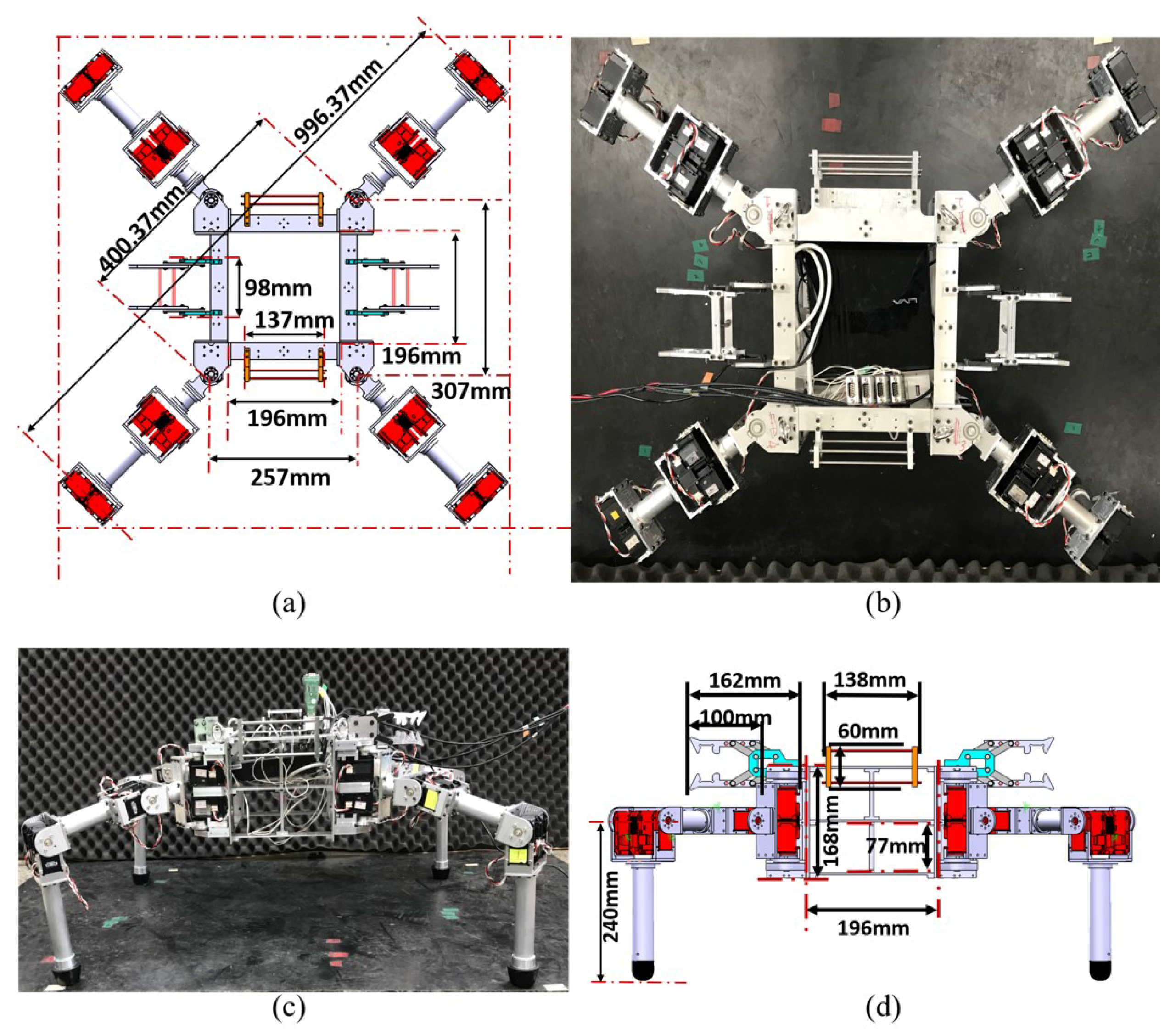
The robot’s body (196 mm × 196 mm × 168 mm, 5 kg) is square when viewed from the top with identically sized rectangular planes on each side in order to facilitate easy connection to other identical robots on every side of its body (Figure 2). The body frame consists of three layers, which is designed for both the installation of electronic equipment and wire management. The divider of the body frame (on each side of the robot) is directly connected to the coupling mechanism. In addition, each corner of the body frame, when viewed from the top, is linked to the first joint of the leg.

2.2. Leg Design

By referring to ant legs’ structure, the conventional multi-leg robot also has a 3-DoF leg structure, for which the orientation of the ants’ leg structure is able to produce hip-yaw rotation at the first joint, hip roll rotation at the second joint, and knee roll rotation (i.e., 3-DoF motion) at the third joint of the body frame. With this difference, mimicking the ant legs’ structure, the design allows the proposed robot to operate a more comprehensive rotation of hip yaw during the combined action.
Accordingly, the four legs of the robot are designed to be identical, each consisting of an upper, middle, and lower link (Figure 2) with the yaw-roll-roll rotations. The lengths of each link from the base are 115.8 mm, 188.5 mm, and 210.0 mm, respectively. Each leg (2 kg) is structured as a circular hollow bar (diameter = 30.0 mm) made of aluminum alloy (6061-T6).
Each joint has a set of two actuators in parallel that provide pure force to support the resisting force from the ground when the robot is walking [17]. In addition, rubber is placed at the bottom of each leg to reduce slipping while walking and to prevent damage from the ground reaction force.

2.3. Coupling Mechanisms’ Design

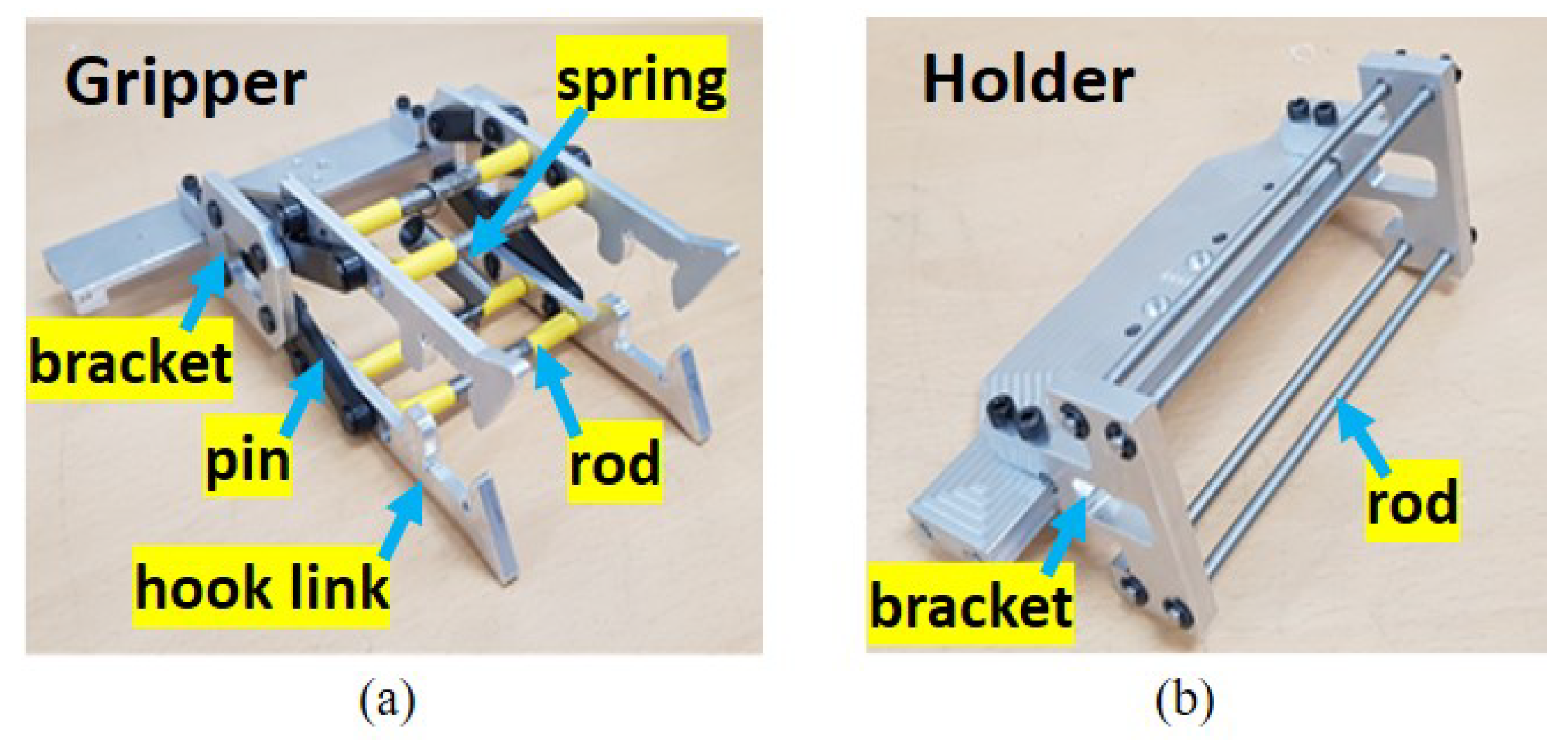
The coupling mechanisms in this study are considered to mimic ants’ claws, for which the end tip of the gripper is designed to have a hook-link structure. The gripper consists of two brackets (75.0 mm × 7.5 mm × 40.0 mm) on both sides and eight pins that are connected to the corresponding hook-links (Figure 3). The holder includes two brackets (58.18 mm × 7.5 mm × 60.0 mm) on the sides that are connected by four rods. These rods are grasped by the hooks from the gripper, thus holding two robots together [18].
A tensile spring (Figure 3) is used to allow limited motion for each link to ensure no intervention between the links. It also provides elasticity for the tensile spring in the hook-link structures to maintain a stable coupling motion. The shape of the hook is designed to simplify the operation of the coupling mechanism, thus facilitating the alignment of the connection between the locking shafts and the hooks. The locking process involves both the driving robot moving close to another robot and the hooks grasping the locking rods [18]. The effectiveness of the coupling mechanism is verified in the Section 5.2.

3. Control System

The architecture of the control system for the developed robotic system is divided into two main parts: the base station and the individual robots. The main role of the base station is to generate a control signal to manage the individual robots (e.g., Robot 1 and Robot 2 in the experiments that follow). In the base station, a mini PC (IntelCore i7 COM Express CPU) runs the high-level robot controllers on the Linux platform (Ubuntu 16.04) together with the use of the Robot Operating System (ROS). The commands transferred by the user at the base station are sent to the respective robots from the operator console.
The robot also includes the same mini PC to receive external data from the operator console at the base station and to initiate robot motion. To achieve this, the control system consists of four components. The first is the network manager (which is a wired connection in this study; this will be replaced with a wireless network connection in the future), which receives external data from the base station. The second component is the perception manager, which receives vision information from the vision sensors (in future work), and the third is the behavior manager, which analyzes the internal data from both the network manager and the perception manager, generating decision information that is transferred to the fourth component, the motion manager, which controls the robot.

4. Methods and Algorithm for the Experiment

To verify the robot design, the following experiments were carried out: (1) walking motion of a single robot; (2) walking action in the combined status.

4.1. Walking Motion of a Single Robot

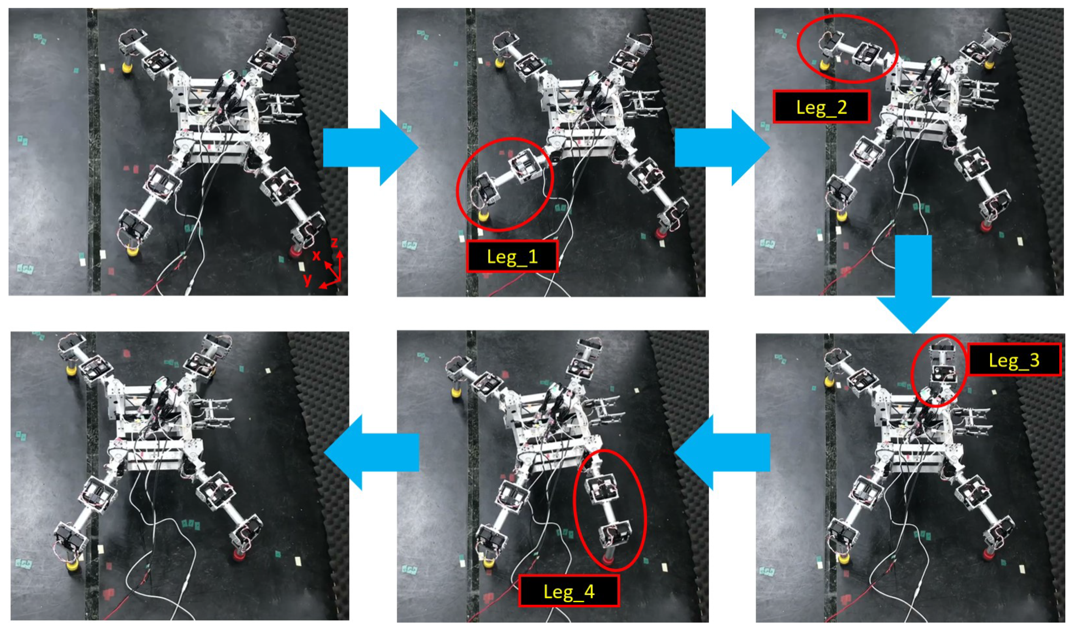
A walking test for a single robot was carried out to verify the functionality of the proposed robot. The walking sequence of a single robot was designed to mimic that of an ant. Past research on ant walking behavior reported that the walking gait of ants is divided mainly into two batches of three legs; this is known as a tripod gait because it looks similar to a tripod standing on the ground [19,20]. As such, the robot should always have three legs on the ground at any point in time to support its body. The gait pattern is designed as follows: Leg 1, Leg 2, Leg 3, Leg 4 (Figure 4). Whereas the pseudo-code for the walking sequence is shown as in the Algorithm 1.
Algorithm 1: Pseudo-code of the robot’s walking sequence.
1:leg1_joint2 and leg1_joint3 → maximum_angle
2:leg1_joint1 → forward_angle
3:For (i=1;3;++)
legi_joint2 and legi_joint3 → initial_angle
Legi+1_joint2 and leg2_joint3 → maximum_angle
legi_joint1 → initial_angle
legi+1_joint1 → forward_angle
4:leg4_joint2 and leg4_joint3 → initial_angle
5:leg4_joint1 → initial_angle

4.2. Walking Motion of Connected Robots

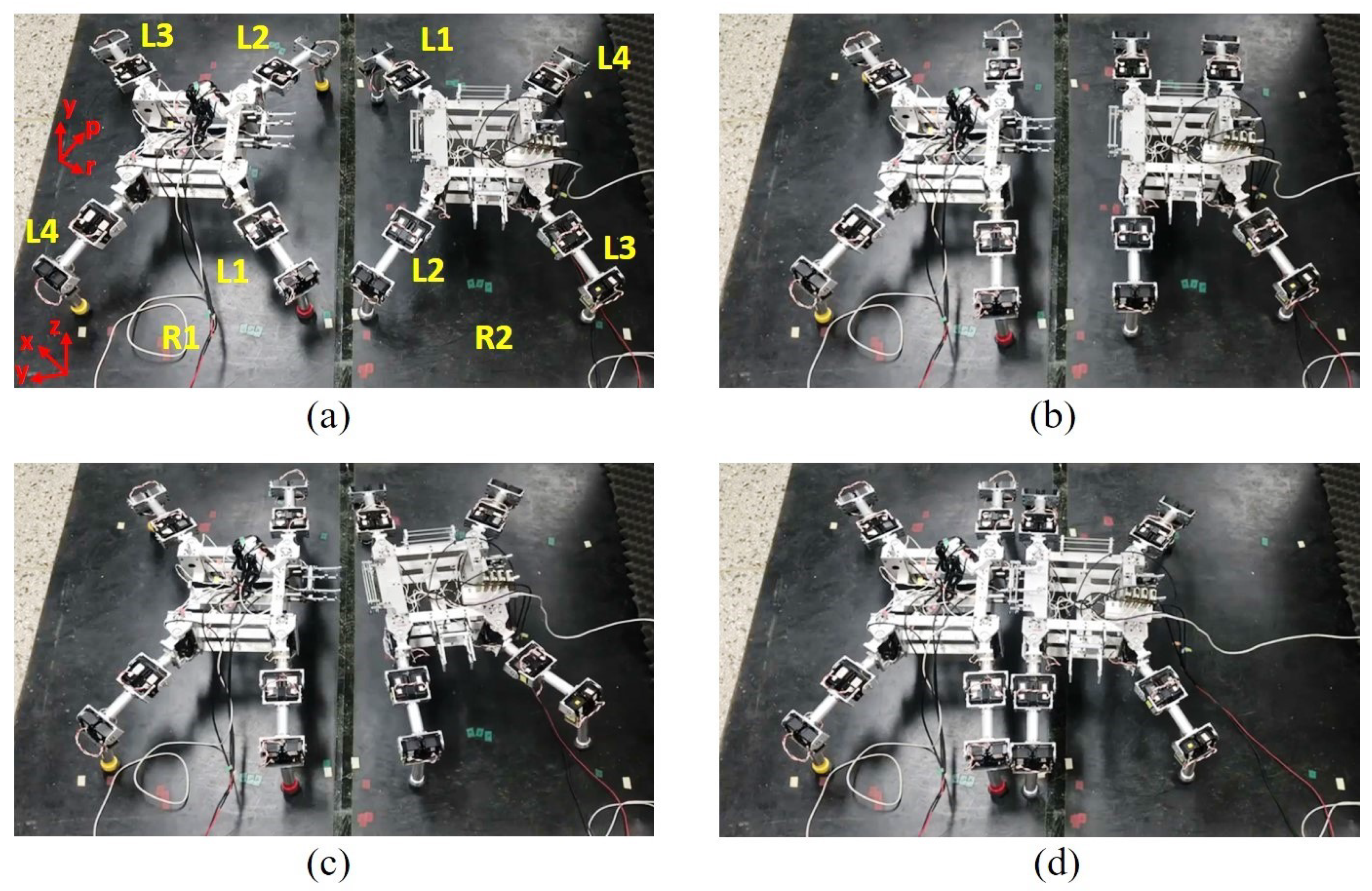
This experiment examined the walking motion of connected robots and the gripping ability of the coupling mechanism. The connection process and walking motion of two identical robots were followed: (1) initiating the movement of Robot 1 and Robot 2 from a static pose; (2) manipulating the legs of both robots so that they walked toward each other; (3) aligning the gripper tips in the locking direction; (4) locking the robots completely; (5) initiating the movement of the front legs of the individual robots (the center legs of the combined robot) to move forward; (6) determining the direction of the hind legs of the individual robots (the legs on each side of the combined robot) to move forward; and (7) causing the hind legs of the combined robots to walk together and move the whole body of the combined robot.
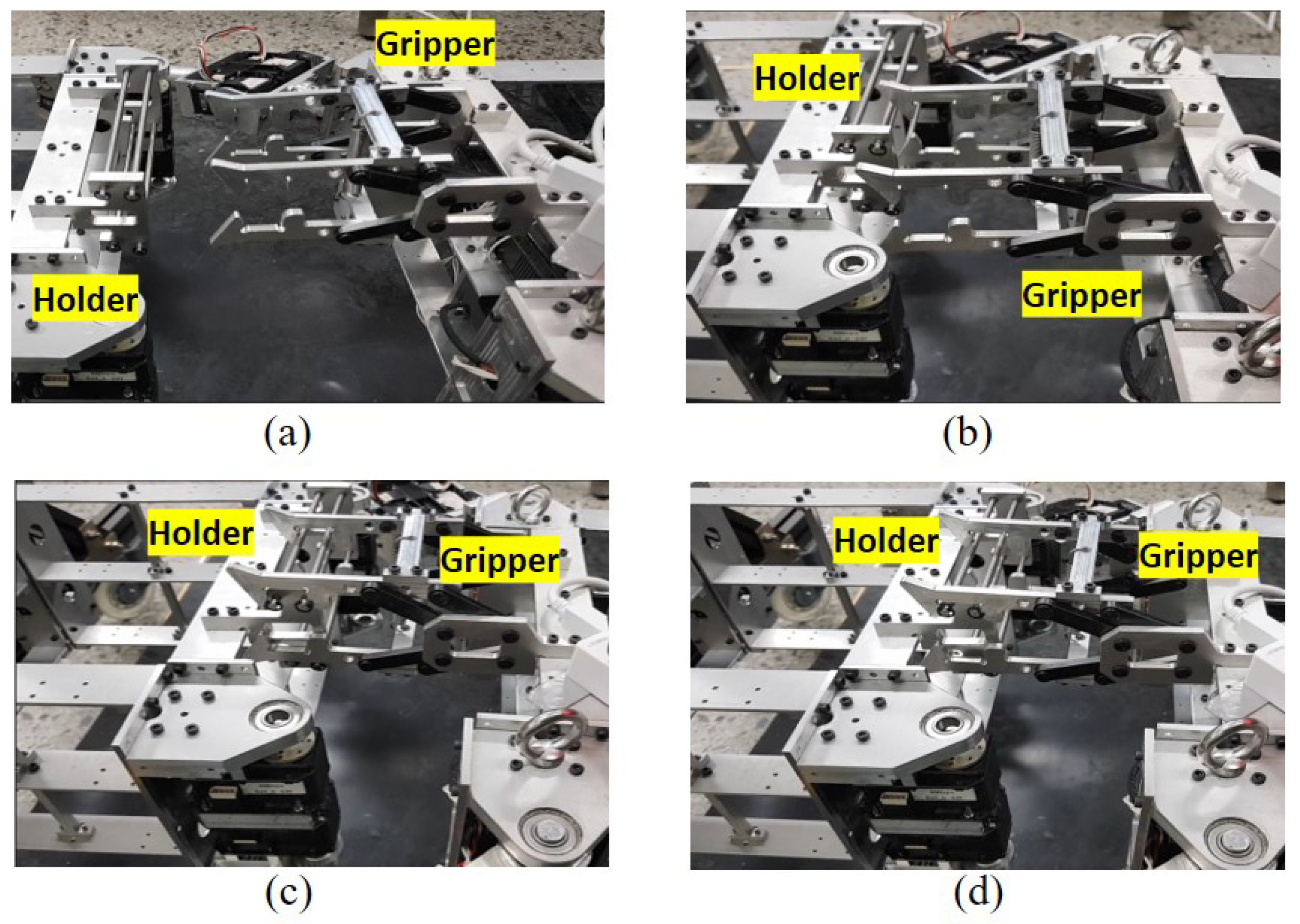
Figure 5 presents a close-up image of the coupling mechanisms in action, while Figure 6 shows that the robots have connected and are walking steadily, which is supported by the measured output of both the encoder and the IMU (Figure 11) for both robots presented in Section 5.2. In other words, the proposed robot effectively realizes a form of the super-organized behavior observed in ants: physical connection and movement.

5. Results

In order to verify the mimicking of the ants’ structure and locomotion behavior, two experiments for basic locomotion were carried out for: a single robot walking (Video S1) and the combined status walking (Video S2).

5.1. Walking Motion for a Single Robot

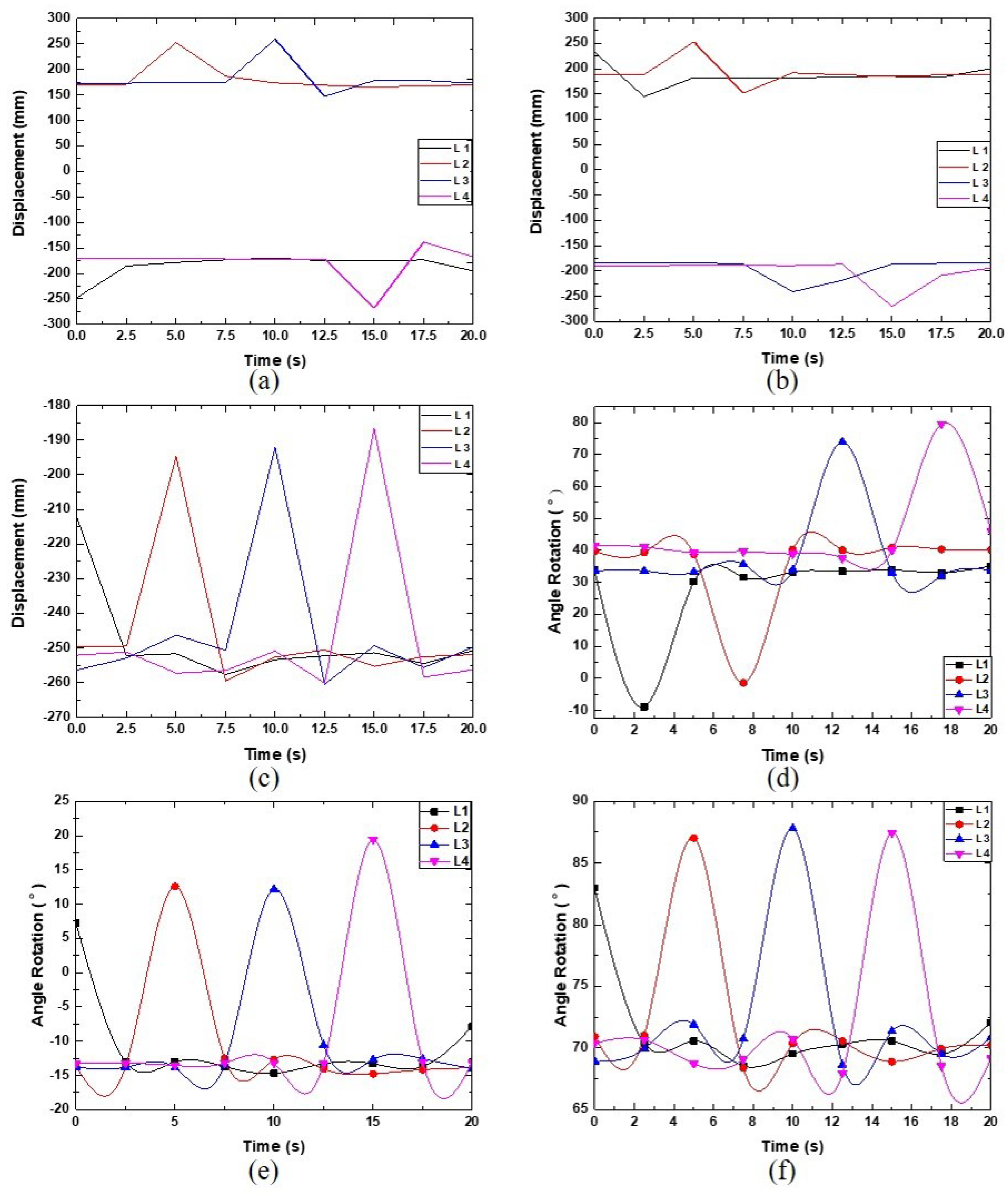
Figure 7a–c displays the foot trajectory for each leg during the walking motion of a single robot with respect to the x-, y-, and z-axes on the base frame of the robot (i.e., the center of the body). Figure 7d–f presents the rotation angle for each joint of the robot’s legs. For t = 0–2.5 s into the motion, the trajectory for Leg 1 in the x-, y-, and z-axes changes from −247.3 mm to −185.3 mm (Figure 7a), 232.6 mm to 144.6 mm (Figure 7b), and −212.5 mm to −252.2 mm (Figure 7c), respectively. At the same time, both Joints 2 and 3 of Leg 1 rotate to their maximum angle of 13.00 ° (Figure 7e) and 87.19 ° (Figure 7f), respectively, to lift Leg 1 off the ground, while Joint 1 of Leg 1 is rotated −10 ° (Figure 7d) to face forward (Figure 4). These results indicate that Leg 1 is walking forward and is the only leg in motion at this time.
The sequence of walking motions remains the same with respect to the time interval for all four legs, with movement first initiated for Leg 1 at t = 0 s, then Leg 2 at t = 5 s, followed by Leg 3 at t = 10 s and Leg 4 at t = 15 s. The proposed robot thus fulfills the static stable walking requirement in that three legs are always in contact with the ground while walking [17].
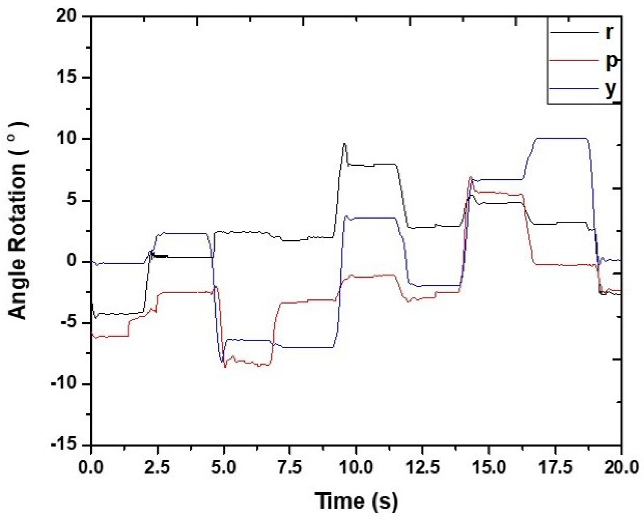
The practical validation of the stability of the single robot walking is provided in Figure 8 in the form of IMU results. These results consist of the rotational angle of the roll (r), pitch (p), and yaw (y) at the center of the robot body while walking in relation to the z-axis, the opposite of the x-axis, and the y-axis, respectively. Although there is an error caused by a delay in the response of the body center to the leg movements while walking, the overall results in Figure 8 show that no overturning occurred. At t = 20 s, which represents the end of a walking motion period, the angle of rotation along the roll and pitch axis is 2.40 ° and 6.25 ° , respectively, which indicates that the body of the robot is slightly tilted toward the left and toward the back, but there is no overturning.

5.2. Walking Motion for Connected Robots

To assess the walking motion of the connected robots (in Section 4.2), the walking trajectories for Robot 1 and Robot 2 are presented in Figure 9, and the rotational angle of the leg joints for the two robots is shown in Figure 10. Table 1 is the summary of the variation of the rotational angle.
During the first 10 s of motion, Legs 1 and 2 of Robot 1 are turned to the side to prepare for the combination with Robot 2, as indicated by the foot trajectories along the robot’s y-axis shown in Figure 9b, which gradually increased from −257.7 mm to −158.0 mm and from −257.4 mm to −149.0 mm for Legs 1 and 2, respectively. As seen in Figure 9e, both Legs 1 and 2 of Robot 2 show the same pattern from 10 to 20 s during the combining process. Corresponding to these observations, Figure 10a,d also shows evidence of a change in the rotational angle at Joint 1 of Leg 1 and Leg 2 of both Robot 1 (1.4 ° and −1.4 ° , respectively) and Robot 2 (−1.2 ° and −0.5 ° , respectively), which reaches its maximum angle after the first 5 s and remains constant thereafter.
Next, Leg 3 and Leg 4 of Robot 2 walk toward Robot 1 during the period t = 20–30 s. As seen in Figure 9d, the trajectory of the foot of Leg 3 changes from −270.5 mm to −179.4 mm along the x-axis of Robot 2’s base frame and then decreases to −291.2 mm, while the trajectory of Leg 4 moves from 268.1 mm to 186.8 mm and then to 283.1 mm. In Figure 9e, the trajectory of the foot of Leg 3 along the y-axis of Robot 2’s base frame experiences a gradual increase, then a decrease (from −252.2 mm to −157.2 mm and then to −251.5 mm), and Leg 4 moves from −258.7 mm to −155.6 mm and then to −253.4 mm. In Figure 9f, the trajectory of the foot along the z-axis of Robot 2’s base frame for Leg 3 and Leg 4 changes from −257.0 mm to −220.3 mm and then to -258.0 mm and from −260.6 mm to −180.8 mm and then to −256.4 mm, respectively. During the same period, Figure 10d–f also shows that the rotational angles for the leg joints of Robot 2 change for Leg 4 and then Leg 3. As observed in Figure 9 and Figure 10, both robots remain still from t = 30 s to t = 48 s, indicating that they have connected.
Because the coupling mechanism holds Robots 1 and 2 together face-to-face, Leg 1 of Robot 1 and Leg 2 of Robot 2 are close together and treated as the left-middle leg of the combined robot, while Leg 2 of Robot 1 and Leg 1 of Robot 2 are treated as the right-middle leg. Therefore, when combined, the robots walk according to the robot locomotion principle, in which four legs are always on the ground (with the left and right middle portions of the combined robot assumed to be one leg) to form a polygon base support, as shown in Figure 9 and Figure 10. As a result, the walking motion of the combined robot can be described as stable [21].
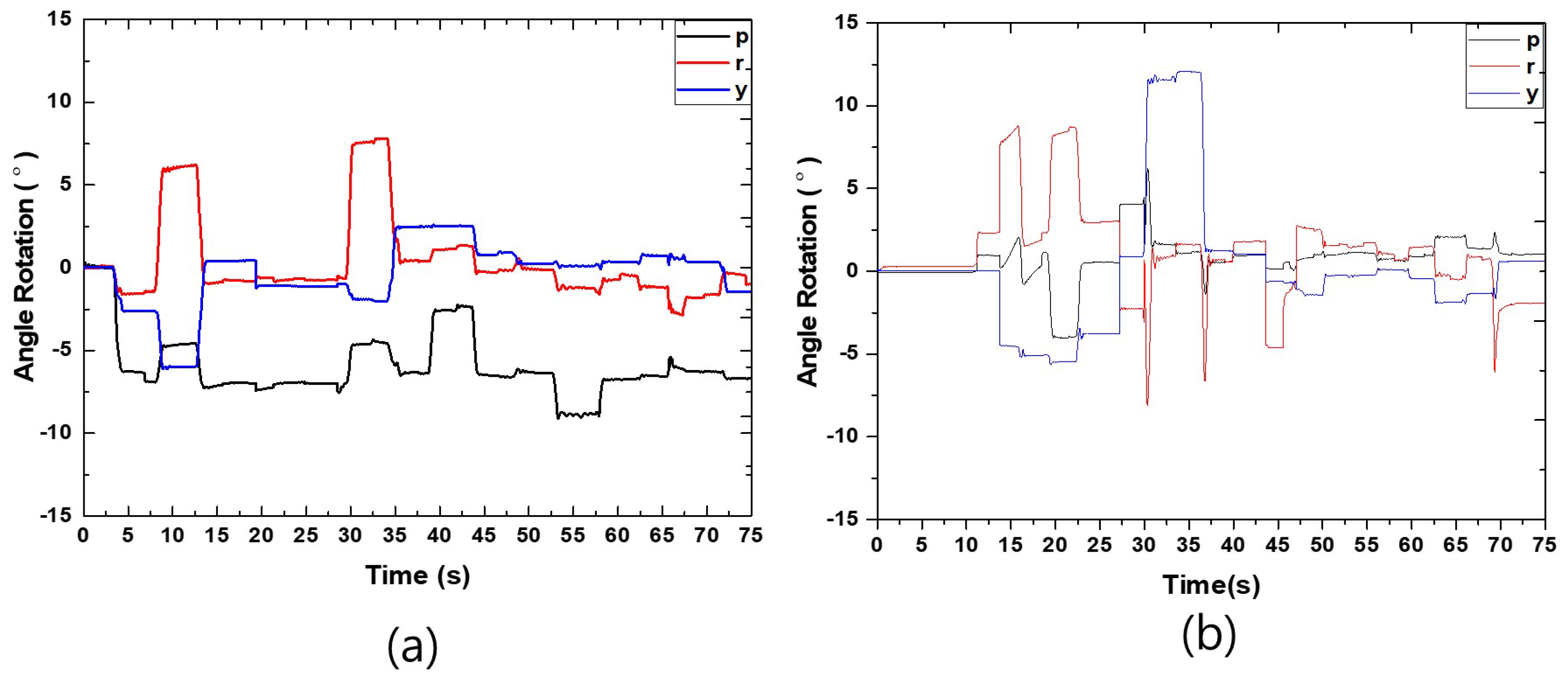
As with the single robot walking test, the IMU results for Robots 1 and 2 are used to check whether the combined robot overturns while walking or not. Figure 11a shows the IMU output for Robot 1, with the z-axis, the opposite y-axis, and the opposite x-axis representing the yaw (y), pitch (p), and rolls (r), respectively, for the rotational angle of the center of Robot 1’s body while walking. The results here support the information provided in Figure 9 and Figure 10. For instance, for t = 5–10 s, the angles along the yaw axis (from 0 ° to −1.5 ° then to 6.1 ° ) and the pitch axis (from 0 ° to −6.3 ° then to −4.6 ° ) both increase then decrease. The trajectory of the legs along the z-axis indicates that they experience a sharp increase and decrease (Figure 10c). That demonstrates that Legs 1 and 2 of Robot 1 move to the side of the robots to prepare for connection.
The results in Figure 11a corroborate those presented in Figure 9 and Figure 10, meaning they can be used to examine Robot 1 (static walking). At the end of the motion, the rotational angle of Robot 1’s base along the roll and pitch axis is −1.1 ° and −6.7 ° , respectively, which indicates that the final posture for the center of Robot 1 tilts slightly to the left and forward, and there is no evidence of overturning. As a consequence, Robot 1 exhibits stable walking when combined with Robot 2.
Figure 11b shows the IMU output for Robot 2, with the z-axis, the y-axis, and the x-axis representing the yaw (y), pitch (p), and roll (r) rotational axes, respectively, of the center of Robot 2’s body. The results here also support those from Figure 9 and Figure 10. For instance, from t = 12.5–17.5 s, Robot 2 experiences the same angle of rotation pattern along the roll and pitch axes as Robot 1. This is because Legs 1 and 2 are also preparing for the combining process. For t = 20–30 s, the IMU output for Robot 2 represents a pattern similar to the single walking motion, indicating that Robot 2 walks close to Robot 1 for the combination process to occur. From 30.0 to 47.5 s, Robots 1 and 2 connect together, changing the angle of rotation along with the yaw (−1.2 ° to 12.1 ° ), pitch (−1.3 ° to 6.2 ° ), and roll (−8.1 ° to 2.7 ° ) axes. From t = 47.5 until the end of the motion, the angle of rotation along with the yaw (between −1.8 ° and 0.6 ° ), pitch (between 0.5 ° and 2.3 ° ), and roll (between −6.1 ° and 2.6 ° ) axes changes, as Robot 2 walks in combination with Robot 1. The reason why there is only a small deflection while walking is because Robots 1 and 2 are held together well.
At the end of the motion, the rotational angles of Robot 2’s base along the roll and pitch axes are −1.9 ° and 1.0 ° , respectively, indicating that Robot 2 tilts slightly to the left and to the back, with no evidence of overturning. As a consequence, Robot 2 also exhibits stable walking when combined with Robot 1.

6. Discussion

The innovation of the combinable multi-legged modular robot inspired by ants’ structure is disclosed. The propose mechanisms are designed to have a total weight of 13.8 kg. This includes a rectangular prism base frame, four identical 3-DoF sprawling-type articulated leg structures, and a pair of link-hook systems. There are a total of 12 teams of actuators installed, each at every joint of the leg.
To reveal the performance of the proposed robot in combining and walking ability, two experiments were carried accordingly. Referring to Section 5, the basic locomotion for both the single mode and combined status mode is examined through the interpretation of the IMU data.
In order to obtain the orientation result of the proposed robots as the solid proof for them to be able to perform regular walking for both cases in the experiments, the IMU sensor was installed in the center of their base frames. Therefore, both the encoder input signal and IMU data were collected appropriately.
As expected, both cases of the walking experiment showed that the robot was able to perform a stable walk. Checking all the IMU results obtained, they fluctuated between −10 ° and 15 ° , which would prevent any overturning of the robot base. Surprisingly, the combination and walking motion brought more stability as the number of legs in stance increased from three to six, as compared to the single walking test. The evidence of the orientation for Robot 1 and Robot 2 (Figure 11) showed a smaller oscillation for both the combined robot bases’ pitch and roll angles compared to the single robot walking result (Figure 8). Although the oscillation angle along the roll axis of Robot 2 was a slightly higher than the single walking robot, the combined robot was still able to have stable walking performance without falling over. The coupling mechanism was capable of holding the base frame of Robot 2 close to Robot 1 and prevented the overturning of Robot 2.
The capability of the coupling mechanisms to hold the two robots in combination with each other was proven through the walking experiment of the merged status. During the process of the combination, the gripper that mimics the ants’ claws together with the use of the tensile spring provided a straightforward combination process. Additionally, with the assistance of this coupling mechanism, the two individual robots connected to each other and formed an eight legged robot to perform walking without any deformation occurring to the structure (Figure 6). From this, the capability of the hook-link system that mimics ant claws was validated.
The overall result from this study achieved the objective of examining both the design and performance of the developed robot that was inspired by ants’ structure. The proposed robot with this newly invented conceptual design successfully expands the physical capabilities of a conventional robot.

7. Conclusions

In this study, the concept design of a combinable multi-leg modular robot inspired by ants’ structure was proposed. The functionality of the proposed robot was investigated by conducting walking experiments in single and combined mode, as well as designing a hook-link structure to connect the individual robots together. The imitation of ants’ structure in the proposed robots was validated in evaluating the capability of a conventional legged robot. It is feasible to use in multi-robot system applications by mimicking ants’ super-organized behavior. Mimicking the locomotion behavior of ants, the proposed robot is successfully verified by broadening the physical capabilities in the combined mode.

Supplementary Materials

The following videos are available online at https://www.mdpi.com/2076-3417/11/4/1379/s1: Video S1: Single robot walking, Video S2: Combined robot walking.

Author Contributions

Conceptualization, H.Y. and C.E.Y.; methodology, C.E.Y.; software, C.E.Y.; validation, H.Y. and C.E.Y.; formal analysis, C.E.Y.; investigation, C.E.Y.; resources, C.E.Y.; data curation, C.E.Y.; writing, original draft preparation, C.E.Y.; writing, review and editing, H.Y.; visualization, C.E.Y.; supervision, H.Y.; project administration, H.Y.; funding acquisition, H.Y. All authors read and agreed to the published version of the manuscript.

Funding

This research received no external funding.

Acknowledgments

This research is supported by the National Research Foundation of Korea (MSIP: Ministry of Science, ICT & Future Planning) (No. 2017R1C1B2005512).

Conflicts of Interest

The authors declare no conflict of interest.

Abbreviations

The following abbreviations are used in this manuscript:
PCPersonal computer
DoFDegree of freedom
ROSRobot Operating System
CPUCentral processing unit
IMUInertial measurement unit
rRoll
pPitch
yYaw
tTime in seconds
LLeg
RRobot

References

  1. Dupeyroux, J.; Julien, R.S.; Stéphane, V. AntBot: A six-legged walking robot able to home like desert ants in outdoor environments. Sci. Robot. 2019, 4, 1–12. [Google Scholar] [CrossRef] [PubMed] [Green Version]
  2. Korein, M.; Veloso, M. Multi-armed bandit algorithms for spare time planning of a mobile service robot. In Proceedings of the AAMAS, Stockholm, Sweden, 10–15 July 2018; pp. 2195–2197. [Google Scholar]
  3. Simoens, P.; Dragone, M.; Saffiotti, A. The internet of robotic things: A review of the concept, added value and applications. In Proceedings of the Future Technologies Conference (FTC), Vancouver, BC, Canada, 15–16 November 2018; pp. 1037–1058. [Google Scholar]
  4. Bellicoso, C.D.; Bjelonic, M.; Wellhausen, L.; Holtmann, K.; Günther, F.; Tranzatto, M.; Fankhauser, P.; Hutter, M. Advances in real-world applications for legged robots. J. Field Robot. 2018, 35, 1311–1326. [Google Scholar] [CrossRef]
  5. Gao, Z.; Shi, Q.; Fukuda, T.; Li, C.; Huang, Q. An overview of biomimetic robots with animal behaviors. Neurocomputing 2019, 332, 339–350. [Google Scholar] [CrossRef]
  6. Andrada, E.; Mampel, J.; Schmidt, A.; Fischer, M.S.; Karguth, A.; Witte, H. From biomechanics of rats’ inclined locomotion to a climbing robot. Int. J. Des. Nat. Ecodyn. 2013, 8, 191–212. [Google Scholar] [CrossRef] [Green Version]
  7. Li, F.; Liu, W.; Fu, X.; Bonsignori, G.; Scarfogliero, U.; Stefanini, C.; Dario, P. Jumping like an insect: Design and dynamic optimization of a jumping mini robot based on bio-mimetic inspiration. Mechatronics 2012, 22, 167–176. [Google Scholar] [CrossRef]
  8. Song, M.; Ding, C.; Yu, C. Workspace analyzing for hybrid serial-parallel mechanisms of a new bionic quadruped robot. Appl. Mech. Mater. 2015, 713, 837–840. [Google Scholar] [CrossRef]
  9. Liljeback, P.; Stavdahl, O.; Beitnes, A. SnakeFighter—Development of a Water Hydraulic Fire Fighting Snake Robot. In Proceedings of the 9th International Conference on Control, Automation, Robotics and Vision (ICARCV), Singapore, 5–8 December 2006; pp. 1–6. [Google Scholar]
  10. Ahmad, G.; Mahdieh, B.; Ako, V. Design, Mechanical Simulation and Implementation of a New Six Legged Robot. arXiv 2020, arXiv:1902.03547. [Google Scholar]
  11. Jessen, K.; Maschwitz, U. Orientation and recruitment behavior in the ponerine ant Pachycondyla tesserinoda (Emery): Laying of individual-specific trails during tandem running. Behav. Ecol. Sociobiol. 1986, 19, 151–155. [Google Scholar]
  12. Groham, J.M.; Kao, A.B.; Wilhelm, D.A.; Garnier, S. Optimal construction of army ant living bridges. J. Theor. Biol. 2017, 435, 184–198. [Google Scholar] [CrossRef] [PubMed]
  13. Shriyam, S.; Mishra, A.; Nayak, D.; Thakur, A. Design, fabrication and gait planning of alligator-inspired robot. Int. J. Curr. Eng. Technol. 2014, 2, 567–575. [Google Scholar] [CrossRef]
  14. McCreery, H.F.; Breed, M.D. Cooperative transport in ants: A review of proximate mechanisms. Insect. Soc. 2006, 61, 99–110. [Google Scholar] [CrossRef]
  15. Madhav, P.; Tamer, A.; Tarek, S. Hardware architecture review of swarm robotic system: Self-reconfiguration, self-reassembly, and self-replication. ISRN Robot. 2013, 2013, 1–11. [Google Scholar]
  16. Lee, J.G. Design of Mutually Combinable Modular Legged Robot. Master’s Thesis, Kyungpook National University, Daegu, Korea, 2019. [Google Scholar]
  17. Ha, J.; Lee, J.G.; Yeoh, C.E.; Lee, S.; Yi, H. Optimal design of a quadruped walking robot’s leg. In Proceedings of the International Conference on Control, Automation System (ICCAS 2018), Pyeong Chang, Korea, 17–20 October 2018; pp. 1723–1725. [Google Scholar]
  18. Yeoh, C.E.; Kim, T.H.; Lee, S.R.; Yi, H. The Combination Funtion for Multi-leg Modular Robot, Bio-mimicked from Ant’s Behavior. In Proceedings of the International Conference on Intelligent Robots and Systems (IROS), Macau, China, 4–8 November 2019; p. 2657. [Google Scholar]
  19. Shamble, P.S.; Hoy, R.R.; Cohen, I.; Beatus, T. Walking like an ant: A quantitative and experimental approach to understanding locomotor mimicry in the jumping spider Myrmarachne formicaria. Proc. R. Soc. B 2017, 284, 1–10. [Google Scholar] [CrossRef] [PubMed] [Green Version]
  20. Zollikofer, C.P.E. Stepping patterns in ants. II. Influence of body morphology. J. Exp. Biol. 1994, 192, 107–118. [Google Scholar] [PubMed]
  21. Böttcher, S. Principles of Robot Locomotion. 2006. Available online: http://users.dimi.uniud.it/~antonio.dangelo/Robotica/2012/helper/leggedRobot/RobotLocomotion.pdf (accessed on 3 February 2021).
Figure 1. The design concept for the proposed ant-like robot is inspired by a variety of robot categories.
Applsci 11 01379 g001
Figure 2. Design of the robot’s body. (a) Top view of the robot design in Catia. (b) Top view image of the robot. (c) Front view image of the robot. (d) Front view of the robot design in Catia.
Applsci 11 01379 g002
Figure 3. Hook-link module. (a) Gripper. (b) Holder.
Applsci 11 01379 g003
Figure 4. Walking sequence for a single robot.
Applsci 11 01379 g004
Figure 5. The coupling mechanisms are used in the combination process. (a) Ready to lock. (b) Contact with locking bar. (c) Semi-locked. (d) Fully locked.
Applsci 11 01379 g005
Figure 6. Combination and walking processes. (a) Operation begins. (b) Ready pose. (c) Robots are approaching each other. (d) Robots combined. (e) Center legs moving forward. (f) Front-left and hind-right legs move. (g) Front-right and hind-left legs move. (h) All legs actuate, and one step is taken.
Applsci 11 01379 g006aApplsci 11 01379 g006b
Figure 7. Displacement of the feet trajectory on the walking motion for a single robot along the (a) x-axis, (b) y-axis, and (c) z-axis. The angle of rotation of the leg joints for a single robot: (d) Joint 1, (e) Joint 2, and (f) Joint 3.
Applsci 11 01379 g007
Figure 8. IMU results for a single robot.
Applsci 11 01379 g008
Figure 9. Feet trajectory for two connected robots walking together. Displacement of the feet trajectory of Robot 1 along with the (a) x-axis, (b) y-axis, and (c) z-axis. Displacement of the feet trajectory of Robot 2 along the (d) x-axis, (e) y-axis, and (f) z-axis.
Applsci 11 01379 g009
Figure 10. Leg joint angle of rotation for two connected robots walking together. Angle rotation for Robot 1 at (a) Joint 1, (b) Joint 2, and (c) Joint 3. Angle rotation for Robot 2 at (d) Joint 1, (e) Joint 2, and (f) Joint 3.
Applsci 11 01379 g010
Figure 11. IMU results during the walking test of the combined status for (a) Robot 1 and (b) Robot 2.
Applsci 11 01379 g011
Table 1. Angle variation of the robot’s orientation.
Robot 1Robot 2
pitch, p−9.121∼0.294 ° −4.010∼6.215 °
roll, r−2.894∼7.825 ° −8.122∼8.774 °
yaw, y−6.118∼2.606 ° −5.657∼12.069 °
Publisher’s Note: MDPI stays neutral with regard to jurisdictional claims in published maps and institutional affiliations.