Article

Testing as-Built Quality of Free-Form Panels: Lessons Learned from a Case Study and Mock-up Panel Tests

Department of Architectural Engineering, Seoul National University of Science & Technology, Seoul 139-743, Korea
Appl. Sci. 2021, 11(4), 1439; https://doi.org/10.3390/app11041439
Submission received: 10 November 2020 / Revised: 25 January 2021 / Accepted: 29 January 2021 / Published: 5 February 2021
(This article belongs to the Special Issue Building Information Modelling (BIM): From Theories to Practices)

Abstract

:
Constructing free-form buildings is very complex due to the difficulty in fabricating the curved façade. To install the façade, the complex geometric shapes of the façade need to be divided into panels. The panels developed are classified into three categories in terms of their curvatures, i.e., planar, single-curved, double-curved panels. The quality of the curved façade is determined by the geometric difference between as-built and as-designed panel shapes. Among the three types of curved panels, the double-curved panel is very difficult to form, showing greater quality discrepancy than the other two panel types. Ensuring the as-built quality of the curved façade is for contractors. The main objective of this study is to enhance small/mid-size contractors’ capacity of managing the as-built quality of the double-curved panel. To meet the study objectives, a case study of a small free-form building and empirical mock-up tests of curved panels were performed and beneficial lessons for the contractors were identified through the tests. Among diverse materials, aluminum and glass-fiber-reinforced concrete (GFRC) were utilized for the mock-up tests. Three-dimensional laser scanning technology was employed to foster the as-built data of the case study project and the mocked-up double-curved panels. The data superimposition method was used to measure the deviation between the as-designed and the as-built data of the case study.

1. Introduction

1.1. Background and Purpose

Free-form shapes play an important role in contemporary architecture. A free-form building refers to ‘all or portion of a building that is sloped, narrowed, deformed, or consisting of irregular curves instead of quadrangle’ [1]. With the advancement of digital design and building information modelling (BIM) techniques, the task of constructing free-form buildings has become increasingly easier. BIM allows the complex geometry of free-form buildings to be visualized. As well, it enables contractors, subcontractors, suppliers and manufacturers of the diverse components of the buildings to accurately acquire the parameters necessary for embodying free forms [2].
Constructing free-form buildings is much more complex than traditional rectangular ones due to the difficulty in forming and fabricating the curved façade. To produce the curved façade, the complex geometric shapes of the façade are divided into panels, i.e., the process of panelization, with forms and sizes that can be manufactured and fabricated economically [3,4]. The panels developed are classified into three categories in terms of their curvatures, i.e., planar, single-curved, and double-curved panels [5]. As the names imply, the planar panel is a flat one without any curvature; the single-curved panel denotes a panel with one directional curvature in a panel; and the double-curved panel refers to one with two or three directional curvatures in a panel.
The quality of the curved façade is determined by the geometric difference between as-built and as-designed panel shapes [6]. The discrepancy brings about the discontinuity of the façade curvature lines formed along the cluster of the curved panels thereby distorting the overall beauty of free-form buildings. Ensuring the as-built quality of the curved façade while meeting the free-form design intent is the responsibility of contractors [7]. To meet the quality requirements, the contractors should understand the distinctive limits of the panel materials used, e.g., plastic, glass, metal, and glass-fiber-reinforced concrete (GFRC), and appropriate fabrication methods to the materials.
Two markets for free-form buildings exist in the construction industry. The first is for the contractors who can accommodate the mass production of the various shapes of free-form panels with cutting-edge computerized numerical control (CNC) based shaping technologies [8]. Projects under this category have been generally very big and capital-intensive, have involved diverse panel materials, and have required technical capacity for innovation imposing objectionable cost burden on the projects. The projects, therefore, have been occupied by renowned international construction firms which are competent enough to utilize the technologies and successfully handle the capital burdens [9]. Small/mid-size firms are rarely able to compete in the market to receive an order for construction. Examples of the projects under this category include the Walt Disney Concert Hall in USA, the Mercedes-Benz Museum in Germany, the Experience Music Project in USA, the Dongdaemoon Design Park in Korea, the Chanel Mobile Art Pavilion in France, the Guggenheim Museum in Spain, the Louis Vuitton Foundation for Creation in France, and so on [7].
The second is to deliver small amounts of free-form panels to a project or to build a small size free-form building as a whole [9]. The contractors who belong to this category in general are small/mid-scale construction businesses in a regional market and mostly utilize traditional forming methods such as roller bending, press bending, and stretch bending, or mold-based forming techniques. While the conventional techniques are much cheaper and easier to approach than the cutting edge forming technologies to manufacture the free-form panels, it is obviously understandable that using those techniques can cause bigger as-built quality discrepancy than the cutting edge methodologies since the techniques depend greatly on the craftsmanship of free-form panel fabricators [6].
According to previous research, among the three types of the curved panels, the double-curved panel is very difficult to form, showing bigger quality discrepancy than the other two panel types, which makes free-form projects overall very complex, often harming their geometrical beauty [10]. While comprehensive research is necessary for supporting small/mid-scale contractors to understand the methods of measuring as-built quality of the curved panel, the behavior of each panel type, the limit of the panel materials, and the proper production methods for the materials, thereby enhancing their project quality management capacity, most of the research in the area of free-form buildings has focused on mass and rapid panel production with cutting edge CNC-based technologies and the geometric design of the curved façade with meagre insight into small free-form buildings [11].
The main objective of this study is to identify empirical lessons learned for the small/mid-scale contractors with which they can enhance capacity of managing the as-built quality of the curved free-form panels. To meet the research objective, the study performed a case study of a small free-form building and the mock-up tests of curved panels. Among diverse materials, the study focused on aluminum and GFRC panels. These two materials have been the most widely used as free-form panels.

1.2. Research Method

The research objectives were met, as mentioned above, through a case study and panel mock-up tests. A real-world free-form building called Haewoojae, a two-story toilet museum with 418 m2 gross floor area built in Suwon-City, Korea in 2007, was identified as a case study subject to measure the difference of the as-built from the as-designed curved panels [12].
Two-staged reverse engineering (RE) applications were implemented to get the as-designed and the as-built data of the facility. The first stage of RE was performed to obtain the as-designed data by use of Digital Project (DP hereafter), the 3D free form-oriented BIM tool developed by Gehry Technology [6]. Since the facility was initially designed in 2007 with 2D AutoCad and Maya program, the 3D engineering information and the curvatures coordinates of the façade panels of the facility have not been available. Through the RE process, Haewoojae was programmed as a 3D BIM model and the curvature types of the façade panels, i.e., planar, single-curved, and double-curved, and their locations and numbers were identified.
The second stage of RE was facilitated with 3D laser scanning technology to obtain the as-built data of the facility. The as-built data was then overlapped with the as-designed data by applying the data superimposition method to measure the magnitude of deviation between the as-designed and the as-built models. Given the superimposed results, the author analyzed what panel types showed bigger discrepancy and how big the discrepancy was along with the panel types.
In order to extend the findings from the case study to more population, a total of eight mock-up panels with planar, single-curved, and double-curved shapes were designed and fabricated, and once again the 3D laser scanning technology was applied to gauge the difference between the as-built and the as-designed mock-up panels.
The author used two materials in forming the mock-up panels, i.e., aluminum and GFRC, to test which material was more capable in lessening discrepancy when used for free-form panels. Four out of eight mock-up panels were made of aluminum while the other four were GFRC. The mock-up panels were fabricated with the support of two companies, which had been engaged in fabricating metal sheet panels and in producing GFRC or fiber-reinforced plastic (FRP) panels by means of the casting technology respectively in the Korean construction market. The author interviewed the managers and engineers involved in the study to figure out the practice and to come up with certain approaches to enhance free form façade quality.

2. Literature Review

2.1. Free-Form Panels Panelization and Optimization

Free-form buildings are much more complex than traditional rectangular buildings due to the difficulty in forming and fabricating their curved façade. To form the curved facade, it should be divided into the shape and size that can allow production and fabrication, which is called panelization [2]. At the design stage of a free-form building, designers create very complex building shapes that reflect their design inspiration. Initial panel configurations to embody these shapes consist of free curves with curvatures that change in many ways, causing difficulty in production and fabrication. The designers need to adjust the initial panel configurations to secure constructability of the panels at reasonable cost while maintaining the desired aesthetic quality of free-form shapes and cluster line smoothness of the panels. The process to change the curved panels with complex curvature into planar panels or the panels with simple curvature without damaging the visual quality of the free-form façade is called panel optimization [3,5].
In general, three approaches are implemented to panelize and optimize free-form façade surfaces: (1) shaping the surfaces into faceted planar panels, which can be triangular, rectangular, or pentagonal; (2) shaping the surfaces into single-curved panels, i.e., smoothly bent strips; and (3) shaping the surfaces into smaller double-curved panels [13]. Research has been performed to develop various panel optimization technologies including the use of regular patterns of planar panel shapes, the application of developable surfaces, and the use of parts of the curves such as sphere, cone, torus, cylinder, paraboloid, and cubic [14,15]. In this research, the three approaches were all illustrated in the panelization of the case study subject.

2.2. Panel-Forming Methods

Panel forming methods are different depending on the materials used. In case of glasses, FRP or GFRC, molds are necessary to make variously shaped panels. Melted glass, FRP, and GFRC are then put into the molds to form the panel shapes desired. Materials such as polystyrene foam, Styrofoam, wood, or metal can be used as the molds depending on the strength required and cost [16].
Molding to pour and solidify material are not appropriate for aluminum or metal panel fabrication. There are diverse methods of forming sheet metal panels including bending, die forming, single-point forming, dieless forming, multipoint forming, hydroforming, and explosive forming [7]. While the choice of the method depends mainly on the cost, curvature of the panels, and manufacturing speed, bending is generally used to fabricate curved surfaces due to its economy. Bending is achieved by roller bending, press bending, or stretch bending [17]. Roller bending involves the procedure of pushing a material between a fixed roller and a curved-surface-forming roller to make a product with the desired curvature. This method is the most conventional fabrication method used for one-way curved panels. A press bending machine pushes and bends a sheet metal panel. Roller bending as well as press bending are typically used to generate a uniformly bent profile and are not suitable for making a bent shape with variable curvatures or double-curved panels. Differently from roller or press bending, stretch bending can be used to create a non-uniform one-way bent profile. Like press bending, stretch bending is not suitable for creating double-curved panels [7].
In accordance with whether heat is provided during bending, bending is classified into cold bending and heat bending [18]. Cold bending has been very common since it is cost effective and workable on site. With cold bending, curved surfaces are produced by forcefully bending and forming flat metal panels along the curvature desired at field temperature without heating. This study utilized cold bending method when fabricating aluminum mock-up panels.

2.3. Reverse Engineering (RE) and Scan-to-BIM

This research included RE to embody the as-designed BIM data of the case study subject. RE, often called back engineering or reverse design, is the process where machines, automobiles, buildings, and other products are deconstructed to extract design information, codes, and knowledge from them [6]. Engineering in general produces drawings through engineering translation and generates products on the drawings. However, in the world of RE, original product drawings of a product are pulled out from the finished product. The RE process, therefore, enables engineers to figure out how a portion of a product was designed so that they can reconstruct it.
Three-dimensional laser scanning technology has been widely used as one of the RE methods in the construction industry [5,6,17]. The technology digitally captures the as-built size and shape of physical objects as a digital three-dimensional representation by use of a line of laser light [19]. It allows contractors to collect the as-are conditions on a project site quickly to deliver both accurate and current data that are to be valuable throughout the design and construction stages. The scan data are then used to monitor progress of a project. The ability to apparently recognize discrepancy between the as-built and the as-planned has been thought as a key component for successful project management that acknowledges remedial decisions to be set up in a timely manner [5].
Unmanned aerial vehicles (UAV), also called drones, have recently performed analogous function to 3D scanners. Both drones and 3D scanners have become critical means necessary to complete the ’Scan to BIM’ cycle [5]. In a Scan to BIM process, the data captured by drones or scanners is imported into a 3D environment by such software that transfers the scan data to the BIM milieu to create either accurate as-built models or to inform the design with the real world surroundings as Pix4D, Cloudworx, Edgewise, Pointsense, and Revit Add-in [20]. Through the Scan to BIM process, the missing design data such as 2D drawings and 3D BIM models are generated.
While a number of previous studies have addressed the distinctive characteristics and specific applications of Scan to BIM in construction projects [20,21,22], in the free-form world, Scan to BIM has seldom appeared to be popular yet. The 3D image-capturing technologies are ideally suited to the measurement and inspection of contoured free-form shapes and complex geometries. However, there have been very few studies that delivered the Scan to BIM applications to real world free-form buildings projects and further research is expected to be performed in the near future.

2.4. Digital Data Superimposition Applications

Superimposition literally means the placement of one image on top of an existing image to enhance the overall image quality. In the construction industry, the Scan to BIM process and digital data superimposition have been jointly applied to develop augmented reality (AR) and mixed reality (MR) systems as a project progress-monitoring scheme, which visualizes the discrepancy between the as-built and as-planned performance on a project [23]. AR superimposes digital information on real-world components, retaining the real world foundation but enhancing it with digital applications. MR is the merging of real and virtual worlds to produce new environments and visualizations, where physical and digital objects coexist and interact in real time. Ratajczak et al. [24] proposed a BIM-based AR. The application combined a location-based management system and BIM to visualize progress and performance of construction works by use of superimposition. Raimbaud et al. presented a MR application based on BIM data and drone videos, allowing off-site construction supervision [25]. It permitted to make annotations about differences between as-planned in BIM and as-built, using superimposition of the two sources. Lim and Ock developed “AR navi-X,” the digital contents of construction management based on AR to support decision making in free-form building projects [26].

3. The Case Study

3.1. As-Designed Data

As mentioned above, a free-form building called Haewoojae was used as a case study to measure the difference between the as-built and the as-designed data of the facility. Figure 1a shows the exterior view of Haewoojae. Since the facility was initially designed in 2007 with 2D AutoCad and Maya program, the 3D BIM information and the curvatures coordinates of the façade panels had not been available. The structure of the facility consists of steel mullions and transoms. Figure 1b represents the configuration of the frames. The facade of the building is composed of galbariums, i.e., zinc-galvanized aluminum panels, with urethane coating. When constructing the facility, the contractor had formed the panels by cold bending in the field according to the facade configuration and welded them to the steel frames. Figure 1c presents construction activities including panel fabrication of the roof area in the facility. The information on the layout of the aluminum panels was not available because the layout of the panels had not been a design element of the facility and coated with urethane coating. Figure 1d demonstrates the curved panel lines that had been fabricated before being coated. Window frames were installed under the panels.
As stated in the Research Method section, the RE process was implemented to get the as-designed façade panel data of the facility. Digital Project (DP), developed by Gehry Technology, was utilized to identify the as-designed façade panel configuration, i.e., the curvature types of the façade panels, such as planar, single-curved, and double-curved, and their locations and numbers. In promoting the RE modeling process of Haewoojae, the designer of the building was invited from an early stage of the modeling to get advice on his major design concerns with the facility and critics on the RE modeling process and architectural shapes from the modeling in order to extract the precise shape of the facility.
In developing a 3D BIM model of the facility, Georgia Tech process to product modeling (GTPPM) was followed. The GTPPM is a formal process-centric product modeling method which enables capture of domain-specific information and work processes through process modeling [27,28]. The following steps were implemented in the modeling: (1) set up baseline for panelization; (2) determine the standard width and height for creating panel joints; (3) create equally spaced lines; (4) establish the standard of expressing geometric forms; (5) clean up complex, geometric shapes and cross line; (6) measure curvature and x, y, z, r values; (7) consider subdivision of panels if needed; and (8) create panels.
Figure 2 represents the step-by-step procedures promoted following GTPPM. Panelization of the curved façade of the facility was performed with rectangular and triangular panel shapes. The basic panel size used in the modeling was 0.8 m × 0.6 m and smaller ones were applied depending on the curvature configuration. The use of 0.8 m × 0.6 m size was appreciated from the Dongdaemoon Design Park (DDP) project built in Seoul, Korea, 2013 [7]. The DDP is a free-form building designed by Zaha Hadid and has become a signature building of Seoul. The surface of the building had been designed to be covered with 45,313 panels, of which the basic panel size was 1.2 m × 1.6 m. Approximately 48% of the panels (21,753 panels) were double-curved 4 mm-thick aluminum panels with folded edge.
The author considered that DDP is a good reference to follow for this study but the panel size of 1.2 m × 1.6 m used in DDP is too big to apply to the case study. The panels of DDP were formed by a multipoint stretch-forming method, which is a hybrid method of traditional stretch bending and multipoint forming, a state-of-the-art technique for forming various curved sheet metal panels by controlling the height of multilayered small presses by means of a multi-post hydraulic press [7]. The author, however, assumed the panels of both reengineered Haewoojae and experimental mock-up panels would be formed by use of cold bending. Therefore, the size of the panels to be modeled and made through mock-up tests had to be reduced. The size of 0.8 m × 0.6 m was selected to be used, which was a half size in both the x and y directions and one quarter of the area of the panels in DDP.
Through paneling the façade of the facility, a total of 533 panels along with four different panel types were identified: 262 planar panels, 204 single-curved panels with curvature less than 200 mm, 63 single-curved panels with curvature more than 200 mm, and 24 double-curved panels with curvature more or less 200 mm. Figure 3 demonstrates the panel types with different colors: red—planar panels; blue—single-curved less than 200 mm; yellow—single-curved more than 200 mm, and green—double-curved panels. Panels with large curvature were seen in the first and second floor joints, the second floor and roof joints, and the front and rear curved areas of the facility.

3.2. As-Built Data

Three-dimensional laser scanning technology was used to obtain the as–built data of Haewoojae. Among a number of laser scanners in the market, the study utilized Leica Scanstation C-10 time-of-flight (TOF) scanner from Leica Geosystems [29]. There are two common operating principles for laser scanning, i.e., TOF and phase comparison [30]. TOF laser scanning computes the coordinates of its surroundings on the basis of the amount of time a single laser signal takes to return to the scanner after being echoed. This process takes place a great number of times until the given range of data assembly is achieved. On the contrary, the phase comparison method conveys a laser beam which is modified by a harmonic wave. When the modulated beam comes back to the scanner, the phase difference between what was conveyed and what was returned contributes to the calculation of distance.
Scan accuracy is an important consideration when using the data from a laser scanner. In scanning an object, a large number of 3D coordinates on the object’s surface is measured in a very short time. Although it is possible to record the object a number of times from different observation points, it is impossible to record the very same points in these repeated observations. Deviations, in consequence, can be noticed after the object has been extracted from the point clouds resulting from laser scanning and modeled. If the geometric properties of the object are known, the deviation of certain points from the object’s surface can be an indication of scan accuracy [29].
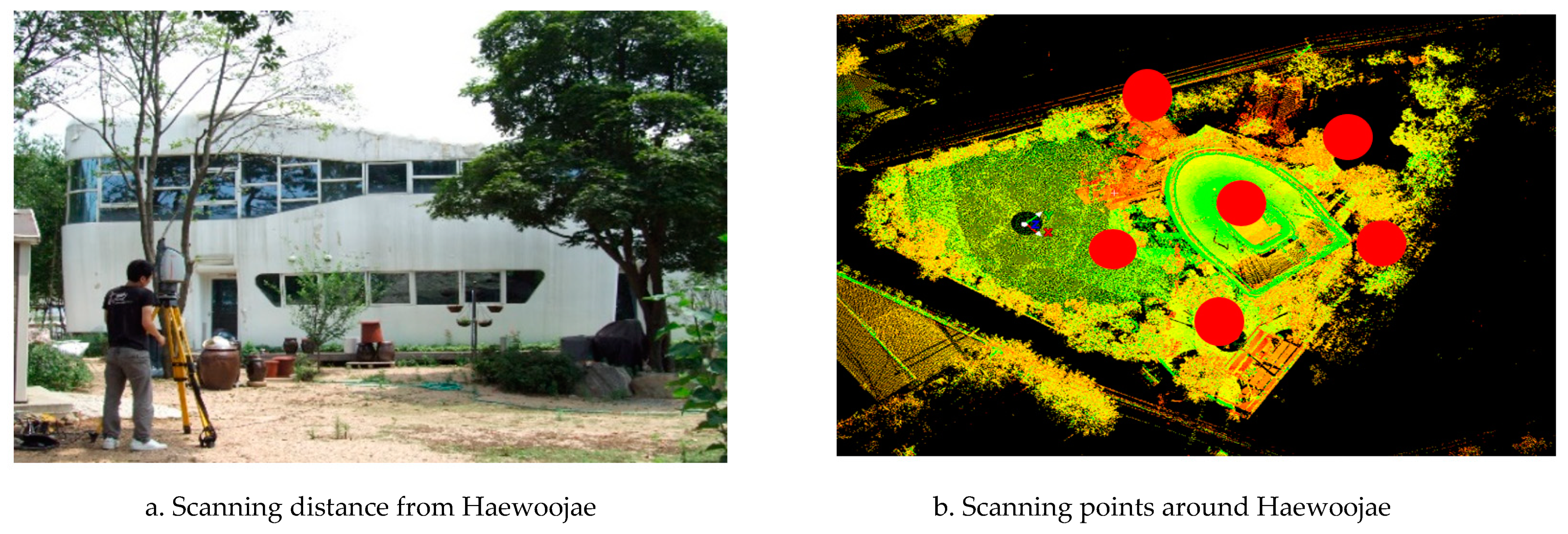
A number of specifications from laser scanner vendors claim that current laser scanning devices provide at an accuracy with a standard deviation of a few millimeters. According to the technical specification for the Leica C-10, the accuracy of the scanned data referred to one sigma is “uncertainty ±4 mm, 50 m range.” Rather than performing an accuracy test for the scanned data of Haewoojae, the study referred to the accuracy indication of the specification since the scanning distance was roughly within 30 m, as shown in Figure 4a.
The volume scanned was approximately 2900 m3 over two stories and 418 m2 of gross floor area of Haewoojae. The initial step of laser scanning was to set up scan points. Figure 4b presents six scan points established to get the point cloud data of the facility, i.e., five points around the facility and one on the roof. The points were arranged to secure enough overlap of scanned areas thereby obtaining a confident shape of the facility. Bright green lines around the center of the five red circles indicated the boundary of the facility scanned. The scanned data were then refined removing unnecessary noise in each scanned area and merged together. The merging process was performed following the overlapped location and shapes in each of the six scanned areas. Based on the merged shape, the building outline and surface were made as shown in Figure 5a.
In general, to model surfaces of scanned facilities, commercial software such as Maya, Rapidform, Geomagic, and Polyworks has been used in the past [6]. However, these applications generate a simple polygon CAD file without delivering the parametric volume elements of scanned objects through automatic conversion of data. Just as the as-designed data of Haewoojae was obtained with DP, the study utilized DP again to produce the surface outlines of the scanned facility data and converted those to BIM parametric data for comparison. Figure 5c shows the final surface model of the facility based on the data from laser scanning.

3.3. Superimposed Data Comparison

As mentioned earlier, the data superimposition method was used to identify the differences of the after-construction results. Comparative analysis was performed on the five regions of the facility as shown in Figure 6 (i.e., location 1, 2, 3, 4, and 5) with respect to whether the curvatures of the panels in each region were accurately maintained. Figure 6 shows the three-dimensional comparison of the facility mass. Red-colored areas indicate that the panels in the areas were overall produced and fabricated as designed. On the contrary, the areas in white color include the panels of which shapes and curvatures were more or less different from the as-designed properties.
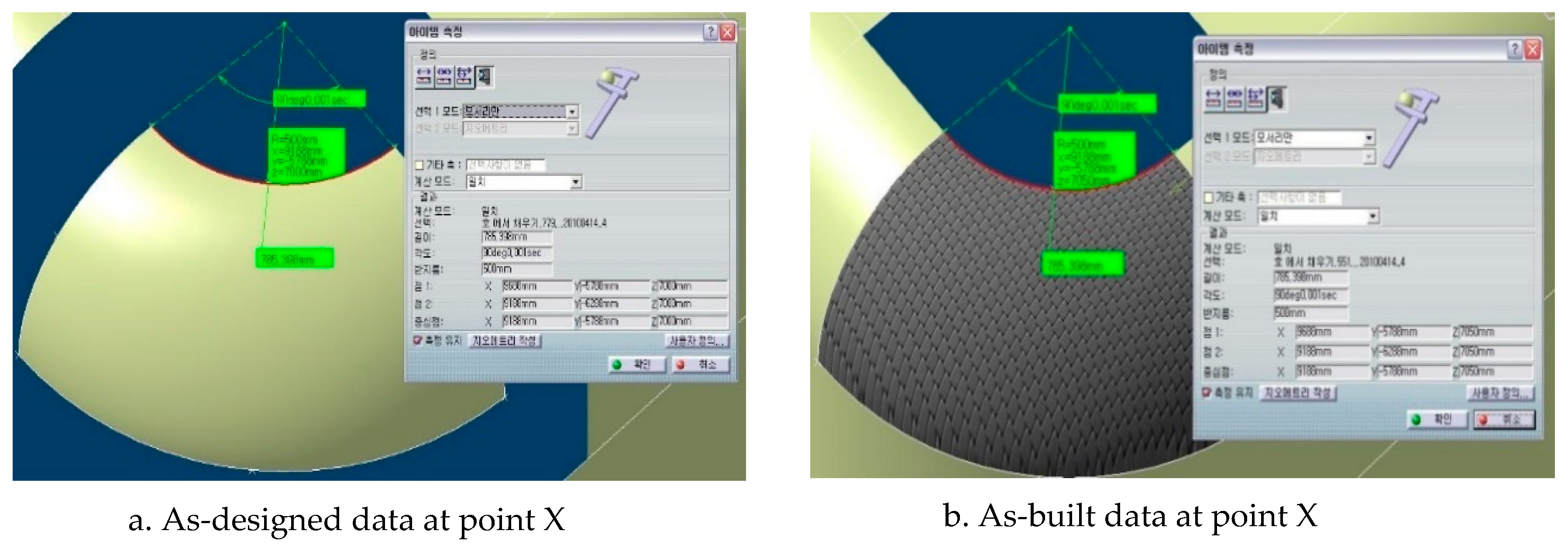
Table 1 summarizes the differences. Discrepant contents in region 1, 4, 5 took place in the single-curved panels while regions 2 and 3 involved double-curved panels and their contents showed different features from regions 1, 4, and 5. Based on the superimposition comparison, it could be inferred that as the curvature got more complex and bigger, the panel changes during forming and fabrication became bigger. In order to illustrate numerically measuring the difference between the as-built and the as-designed data, spreadsheet application was performed along with one panel in region 2. Figure 7a,b present the measurement results delivering the X, Y, and Z coordinates of a specific point on the as-designed panel (X, Y, Z = 9188, 5788, 7000) and the as-built panel (X, Y, Z = 9188, 5788, 7050).
The existence of a 50 mm difference of the Z coordinate means that the designated panel at region 2 was constructed 50 mm higher than initially designed, and the panels that were next to the panel also would be twisted from their original coordinates because of this error. This twisting could cause lifting of panels and panel joints, water leakages, and finish materials falling off when fixing the panels to the main or sub-frames.

4. Mock-up Fabrication

The main objective of this research is for the small/mid-scale contractors to enhance the understanding of the as-built quality of free-form panels in accordance with curvature types. While the best practice to meet this research objective is to perform empirical tests using diverse panels in real-world case studies, there are very few free-form buildings available to test and furthermore, contractors who build free-form buildings do not want to use their facilities as case study objects where the laser scanning technology is used to precisely indicate the quality of built outputs.
Instead of finding case study subjects, the author came up with utilizing free-form panels mock-up tests. This would help to make the findings from Haewoojae more reliable. Among diverse materials used as free-form panels, aluminum and GFRC were utilized in the study. A total of eight panels were made with the two materials, that is, four aluminums and four GFRCs. Aluminum is a lightweight, silvery white, and nonferrous metal [31]. Since it has a density lower than those of other common metals, it is soft and ductile thereby widely used as the material for building components. GFRC is a concrete which involves high-strength, alkali-resistant glass fiber embedded in a concrete mixture [32]. It has been mainly used in exterior building façade panels and architectural precast elements. In the process of performing the mock-up tests of the two materials, it was expected that the small/mid-scale contractors could extend their comprehension regarding the pros and cons and the specific considerations of the materials in forming free-form facades.
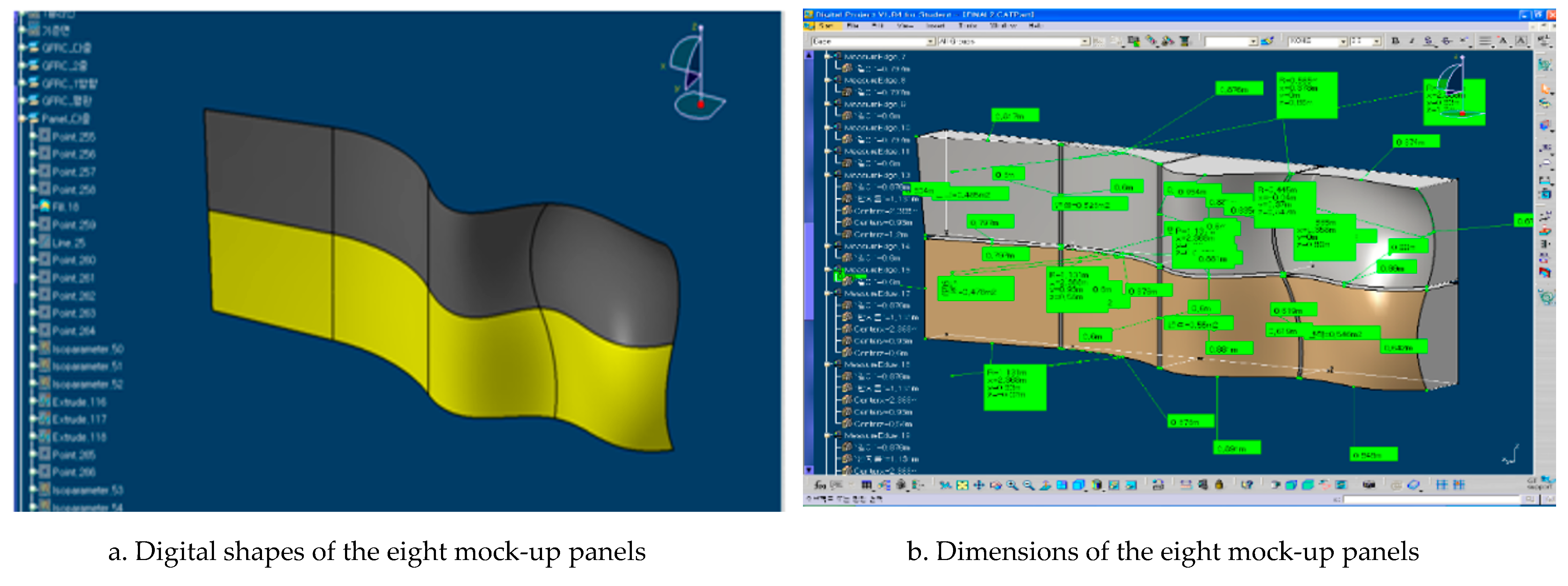
At each material context, one planar panel, one single-curved panel with curvature 200 mm, and two double-curved panels were produced. Figure 8a shows the digital shapes of the mock-up panels modeled with DP. Four dark-colored panels were designed to form with aluminum and the greens with GFRC. The first two panels in each row were planar, the second single-curved panels, the third double-curved panels having curvatures in three coordinates, and the fourth double-curved panels with two coordinate curvatures. Figure 8b presents the planned dimensions of each mock-up panel. The horizontally reflected size of all the panels was 0.8 m × 0.6 m and thickness 4 mm. These conditions were exactly the same as the reengineered Haewoojae panel size and thickness.
During the production of the mock-up panels, six experts from the two material companies were in attendance and advised on the characteristics of the materials, fabrication, equipment usage, and surface machining methods. After testing, the author interviewed them to find hidden and visible difficulties in forming the panels, management points for free-form engineers to bear in mind, and proper approaches to get high-quality as-built products of free-form facades.

4.1. Aluminum Mock-up Panel Production

Constructing free-form panels in general requires 2D fabrication drawings. Figure 9 shows the 2D fabrication drawings of the double-curved mock-up panel of the study, which were extracted from the 3D BIM modeling data. The single-curved surface had one curvature value so that the 2D drawings could be easily defined from the 3D BIM data, but, as for the double-curved surface, points and lines in the drawings should be approximately drawn with a certain range of error and close attention needed to be paid during the actual production of the panel so as to keep the error within that range [5].
As stated earlier, carving, molding to pour, and hardening material are not appropriate for metal panels. Roller and press bending are techniques commonly used for curved metal surfaces. In the case of roller bending, the radius of a curved surface must be more than 200–300 mm [7]. If the radius is less than 200 mm, then press bending is used. The mock-up aluminum panels of the study were produced by both roller and press cold bending techniques. Metals are bent either at room temperature or with application of heat. Cold bending forcefully bends and fixes flat, thick, sheet metal pieces along the curved surface on site at room temperature [18].
During roller bending, the aluminum sheet was placed between a surface controlling roller and a fixed roller set. Both roller bending and press bending are typically used to produce a uniformly bent profile, and are known that those are not suitable for creating a bent shape with varying curvatures or double curvature panels. When producing the planar and single-curved panels in the study, the sub-frames were in the first place cut with a CNC machine and the four sides of a panel were assembled using bolts before fixing a sheet on top. Figure 10 shows the single-curved panel fabrication process performed.
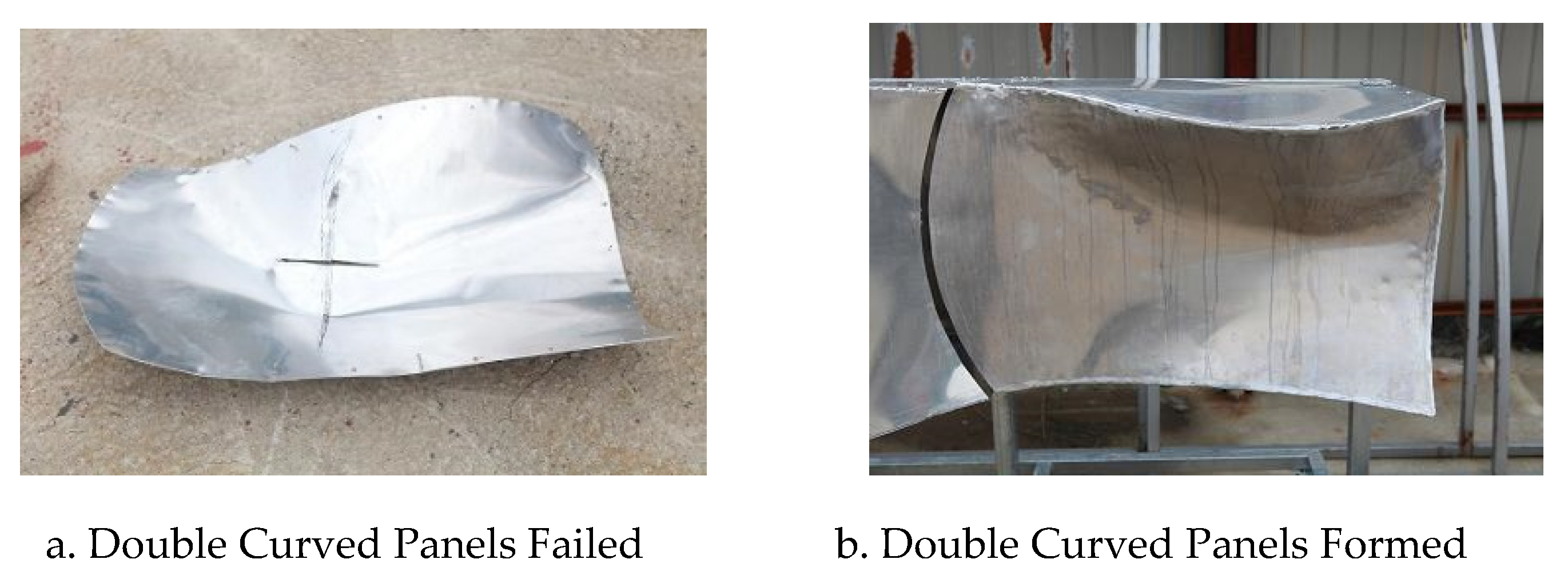
Unlike the planar or single-curved panel, the double-curved panels were likely to return flat by tensile force so that an intermediate sub-frame seemed to be necessary just in case in the mock-up production. With the engineers engaged in forming mock-up panels, the double-curved panels were formed with the combination of press bending with hammering by means of their panel-forming proficiency following the procedures shown in Figure 10. During the forming operation, it was found that the double-curved panel with concave curvature (the fourth panel in the upper row of Figure 8a), which was the double-curved panel with two coordinate curvatures, could be fastened to the mainframe by its edge with small deformation (see Figure 11b).
But in case of the convex curvature, i.e., the double-curved panel with three coordinate curvatures (the third panel in the upper row of Figure 8a), the panel got destroyed shortly after fabrication and the sub-frame was necessary in addition to the mainframe to maintain its curved shape. Figure 11a shows the destroyed double-curved panel. While more specific test and analysis would be required, it was thought that the panel could not bear bending stress imposed to form the convex-shaped double curve with three coordinate curvatures.

4.2. GFRC Mock-up Panel Production

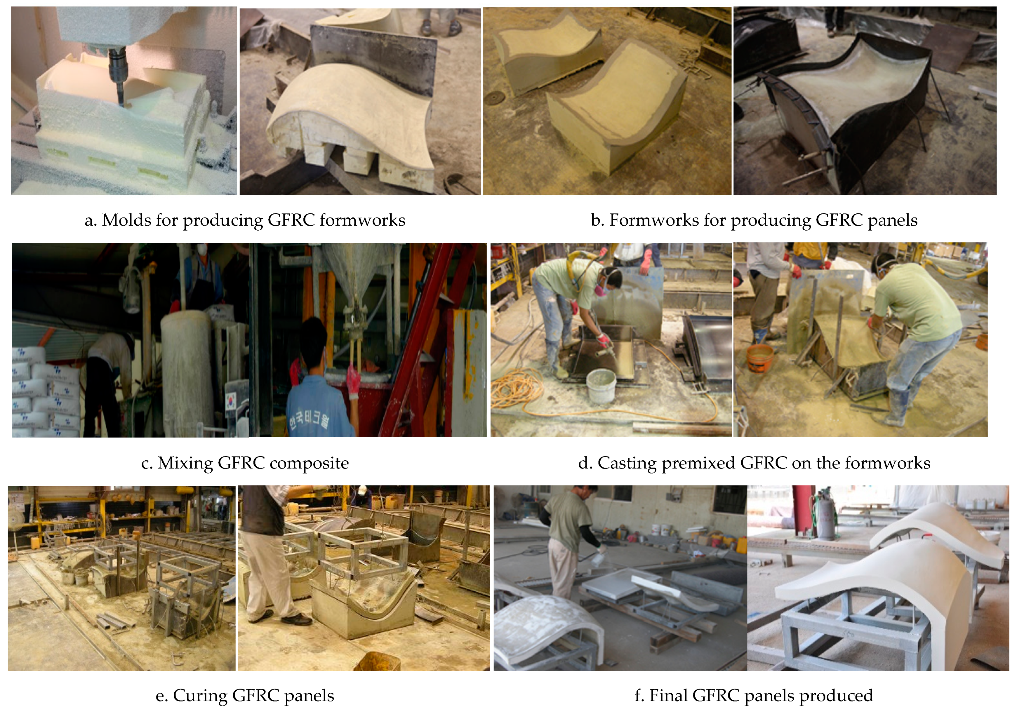
As mentioned earlier, four mock-up panels were formed with GFRC in the study. In manufacturing the GFRC panels, the significant activity was to fabricate four different shapes of formworks to form the panels. Since it was not possible to use a structured formwork for free-form façades such as Euro form or aluminum form, specific formworks had to be produced and in the first place, molds had to be made as the bases of the formworks. Molds can either be made from wood or Styrofoam and Styrofoam was used in the study. Four molds were produced by entering their 3D geometric information into a CNC machine as shown in the left picture of Figure 12a. After manufacturing the molds, formworks were then made by pouring concrete onto the molds. The right picture of Figure 12a shows that steel panels were fixed to the sides of one of the molds on which concrete was supposed to be poured to form a formwork. Figure 12b presents the concrete formwork bases produced (left picture) and the complete formwork consisting of the concrete base and steel side panels (right picture).
GFRC materials were then mixed in the batcher plant shown in Figure 12c. GFRC is in general made by combining a mixture of fine sand, cement, water, other admixtures, and alkali-resistant (AR) glass fibers [32]. The mixture used in the study was the typical composite used in the company involved in the study including ordinary Portland cement, fine sand, polymer, water (water to cement ratio 0.3), and alkali-resistant glass fiber with the length of 12 mm, density of 2.70 g/cm3, breaking elongation of 2.5%, and the ZrO2 content of 16.7%. The quantity of fibers added to the mortar was 3% of the total mix weight.
In casting GFRC on the formworks, the study utilized a premix method. There are in general two different techniques to make GFRC elements in the marketplace, referred as spray up and premix respectively [33]. While the spray-up method creates very strong GFRC due to the high fiber load and long fiber length, it requires a costly operation. The premix method mixes short precut fibers with the fluid concrete mixture and the composite of concrete and fiber is then poured or sprayed into molds. Figure 12d presents that the engineer sprayed the face coat of GFRC into the formwork (left picture). After that, GFRC back-up mix was then sprayed with a spray gun on the face-coated formwork (right picture). Two layers of GFRC back-up mix were placed up sequentially and compaction with rollers was performed at each layer. Through the spray and compaction process, the fibers in the composite were oriented randomly within a horizontal plane and laid flat.
Figure 12e represents the curing process of the GFRC mock-up panels. After curing, the formworks were then taken off from the panels as shown in Figure 12f and the panels were painted with two coats of the desired color as the final step of manufacturing the mock-up panels.

4.3. Mock-Up Data Analysis

The laser scanning technology was used once again to analyze the as-built quality of the mock-up panels. In doing so, among the eight mock-up panels, the author focused on the two double-curved panels with three coordinate curvatures (the third panel of each row in Figure 8a) since that type of panels had been known the most difficult to form, showing critical discrepancy harming the beauty of overall free-form façade. The study expected that the analysis of the two panels would deliver valuable lessons that would be applicable to other types of panels for the small/mid-scale contractors.
Differently from the case study of Haewoojae, the study did not use data superimposition. Instead, the two mock-up panels were scanned and using the practice in Figure 7, the as-designed and as-built X, Y, Z coordinate values at four corners of each panel were compared. Each of the scanned panels was labeled (C), i.e., aluminum panel and (C-1), that is, GFRC panel, and the four corners labeled p1, p2, p3, and p4 as shown in Table 2. Table 2a,b present the coordinate values. The origin of the X, Y, Z coordinates was at the lower right-hand side corner of the bottom right-hand side panel.
Table 3 summarizes the discrepancy of the coordinate values at each corner of the as-designed and as-built aluminum panels. Considering the maximum difference value of the GFRC panel shapes is 4 mm (Z direction) at p1, it is very obvious that the aluminum panel demonstrated much bigger discrepancy than the GFRC panel. The study inferred this tendency would be explained in conjunction with material features, forming methods, or craftsmanship level in handling free-forms. The inferred issues became the main subjects to be discussed with the experts in the interview. The following section of the study “Lessons Learned” will summarize the findings from the interview.
Table 4 shows the numerical amount of the as-built discrepancy of the two panels (C) and (C-1). The linear distances between two points at four edges as well as the diagonal distances of the panels were measured based on the laser scanned data. Table 5 presents the aluminum production allowance designated by the Korean industrial standard [5]. Since the allowance is for a planar panel, it is questionable to apply it to the mock-up test results in Table 4. However, considering the size of the mock-up panels, the as-built quality of the aluminum panels were too big to accept as reasonable.
Whereas there is no production tolerance standard of GFRC panels in Korea, the general practice in the market is 3 mm for a planar panel with length 5 m × 2.5 m [9]. Just like the aluminum mock-up test, the GFRC panels also showed bigger deviation numbers than the market practice.

5. Lessons Learned and Limits

Through the cade study of Haewooje and the test of eight mock-up panels, it was empirically found that, as previous research had identified, double-curved panels provided more difficulty than plane or single-curved panels in securing the as-built quality. The discrepancy of the panels will pose problems like twisting at the time of fixing a number of panels side by side on the main and sub-frames of the free-form façade structure. This twisting can also lead to other defects in the long run such as bulging, leakages, and falling off of some components, and, by consequence, harming the overall aesthetics of a free-form building.
The study results were discussed with six managers and engineers involved in the mock-up panels test to investigate their opinions and perception regarding necessary approaches to securing the as-built quality and handling the difficulties in forming free-form facades. The contents of the discussion were summarized as lessons learned for the small/mid-scale contractors valuable to address in their future free-form projects.

5.1. Lessons Learned

The engineers emphasized in the first place contractors should understand the distinctive features of materials contracted to use. They pointed that the in case of metallic materials including aluminum, the biggest drawback would be spring-back. Spring-back is defined as ‘the amount of elastic distortion a material has to go through before it becomes permanently deformed, or formed [18,29].’ Three factors were investigated through the literature review as critically influencing the amount of spring-back of metal, i.e., size of segment, bend angle, and bend curvature. The contractors need to reflect the attributes in planning to fabricate metal free-form panels lest they should meet unexpected as-built quality.
The next issue deliberated was using proper forming methods to the materials. As stated earlier, bending techniques including roller bending, press bending, and stretch bending are conventional methods to economically bend metal panels. According to previous research, those are not suitable for producing double-curved panels but are for a uniformly bent profile, that is, a single-curved panel [7]. In the mock-up tests, however, the engineers fabricated the aluminum double-curved panels by forceful cold bending with roller and press as well as hammering on site. The numbers in Table 4 and Figure 11 show unfavorable results and empirically demonstrated that the previous research is reasonable to refer to.
In choosing a suitable forming method to the materials, one of the issues significantly highlighted in the discussion was the panel production cost by the method. The cost of forming free-form panels obviously differ depending on the shapes of the panels and the forming techniques to produce the panels. The author performed a market research as a part of the study to investigate the unit cost of fabricating the mock-up panels according to the four panel types [17]. Four companies with a different technique in Seoul, Korea were contacted to request their cost estimation. The first and second companies were Korea-based and had worked with metallic materials and GFRC respectively. The third and fourth companies were Korean branches of international enterprises specializing explosive forming and hydroforming techniques respectively. The cost the first company suggested was $2250/m2 for a planar and single-curved aluminum panels by roller and press bending and the second company $190/m for GFRC panels. The third company offered $12,000/m2 for a simple double-curved panel and $18,000/m2 for a complex double-curved panel by explosive forming, and the fourth firm $18,000/m2 for a simple double-curved panel by hydroforming and no estimation for a complex double-curved panel. The estimation seemed not to be reasonable and could not be bearable so that the author decided to form all the aluminum mock-up panels with the first company by means of forceful cold bending with roller and press. However, the following comment from previous research paradoxically advocates the wide cost range investigated: “Processing unit costs for curved panels are classified into five grades, grade A to E according to the production difficulty. For grade A panels, which are the easiest to fabricate, the processing cost is approximately five times that of planar panels. Grade E curved panels, which are the most difficult to fabricate, cost three to four times more than Grade A panels, which is approximately 20 times more than planar panels [7]”.
Free-form designers in the design stage determine the shapes of the panels, identify the possible panel forming techniques, and estimate initial project cost, however, their concern is not cost but design. Their cost estimate is mainly to provide a preliminary estimate for selecting a suitable contractor through a competitive bidding for construction. Kavuma et al. [10] had identified the cost overrun risks in free-form projects. Most of them were closely related to free-form panel fabrication such as lack of project-specific customization of fabrication technologies, poorly defined project scope at the time of budgeting, inappropriate subcontractor selection for free-form facades, mistakes in quantities and cost estimate, and unclear specification or scope of work. Contractors must bear in mind that those risks definitely belong to them. They should examine in the bidding stage the constructability of the panel shapes and identify suitable forming techniques in terms of technical as well as cost concern. They should perform a market study to precisely re-estimate fabrication cost of free-form façade. As well, once a contract is awarded, then must focus on the project budget limit and keep an eye on completing the project under budget.
The other issue addressed is the need for preparing design change in the construction process. Design change is in general requested by project owners, designers, and sometimes contractors to resolve constructability matters. Design change in most cases is accompanied with construction cost increase. In order for contractors to protect themselves against unfavorable design change, they need to understand three approaches to panelize and optimize free-form façade surfaces: (1) shaping the surfaces into faceted planar panels; (2) shaping the surfaces into single-curved panels, i.e., smoothly bent strips; and (3) shaping the surfaces into smaller double-curved panels. In conjunction with spring-back of metallic material, larger area segments tend to have more spring-back than smaller ones. As for bend angle, the sharper the angle, the lesser the spring-back. As well, the bend curvature has a profound effect on the success of the bending operation and the attainable curvature depends majorly on the material thickness and material hardness.
Mildly double-curved panels can be cut as planar panels and cold-bent on site. Ock [9] commented that while the recent development of CNC shaping technology has simplified the production of double-curved metal panels, the production cost is still very offensive. In cases where only cold bending is available for free-form façade fabrication, it is better to design a façade surface having shapes and curvatures that can be divided into smoothly bent single-curved panels rather than using complex double-curved surfaces [9]. As well, he added that providing a certain range of tolerance in the panel spacing to the extent where the visual continuity of curvature among panels is maintained is necessary to obtain aesthetic products. As an example of the panel spacing and its tolerance, the DDP project, aforementioned in the Section 3.1. As-Designed Data can be referred to. The project involved a total of 45,133 panels, which consisted of 21,738 double-curved panels (48.2%), 9554 single-curved panels (21.2%), and 13,841 planar panels (30.7%). As a matter of course, each of the panels was manufactured as accurately as possible so that the panels could form a smooth surface, but 25 mm spacing between the double-curved panels were maintained and the tolerance value was 2 mm in any direction [7].
Managerial concern addressed in the discussion was the project delivery methods that would be fit to delivering free-form buildings. There are several project delivery methods commonly used in the market place such as design-bid-build (DBB), design-build (DB), and technical proposal (TP). Many of the monumental free-form buildings constructed in the world have been procured by DBB, i.e., designed by world-renowned architects selected through the international design competition and constructed by competitive contractors chosen through a price competition. However, the DBB contains an obvious pitfall in light of design and construction co-work perspective.
Depending on the delivery method, the level of collaboration between a designer and a contractor is quite different. DBB allows little room for them to work together in the process of construction since design and construction are clearly separate and under different contracts. In consequence, design changes must be taken place and cost increase is inevitable. While the project delivery method would be actually chosen by project owners, it was insisted that since private small and mid-size projects can be in general negotiable from the project initiation phase, with project owners in selecting a designer and a contractor, they need to address DB methods appropriate to free-form buildings having a close co-work basis and thereby enhancing the as-built project quality and preventing the project cost from being escalated.

5.2. Limits

Although the discussions and findings from the study are expected to be more or less beneficial to the small/mid-scale contractors of free-form buildings for securing quality free-form products, there are certain limits to bring out advanced inferences for future application due to the limit of the case study material and the number of mock-up tests. As more free-form projects are built in the future, the author will perform advanced research to deliver more reliable findings.
Many small/mid-scale contractors understand the concept of BIM and its possible application areas, however, in general they are not exposed widely to BIM environment and are not good at co-working with BIM as a consequence. Although the Scan to BIM applications using 3D image capturing technologies such as laser scanner and drone are ideally suited to the measurement and inspection of contoured free-form shapes and complex geometries, there have been very few applications to real world free-form building projects. As more contractors widen their experience in those fields, the as-built quality of free-form façade can be enhanced furthermore and more advanced research is expected to be performed to improve the quality.

6. Conclusions

Free-form buildings are known to be difficult to construct due to their unique façade shapes and nonconformity to conventional building techniques. Free-form facades require cutting-edge accuracy in the design, panelization, optimization, fabrication and installation of façade panels in order to be delivered as intended by designers. Therefore, utmost care should be taken during each of those stages as any mistake could lead to dire consequences for the project. The choice of material and method of production of the facades has always been a point of concern for the free-form designer and contractor.
The panels of free-form facades involve three categories in terms of their curvatures, i.e., a planar, a single-curved, and a double-curved panel. Quality of the panels is determined by the geometric difference between as-built and as-designed panel shapes. The difference causes the discontinuity of the façade curvature lines and distorts the overall beauty of the buildings. According to previous research, among the three types of the panels, the double-curved one is very difficult to form and shows bigger quality discrepancy than the other two panel types.
The main objective of this study is to identify empirical lessons learned for the small/mid-scale contractors on which they can enhance capacity of managing the as-built quality of the curved free-form panels. To meet the research objective, the study performed a case study of a small free-form building and the mock-up tests of curved panels. Among diverse materials, the study focused on the aluminum and GFRC panels. The two materials have been the most widely used as free-form panels. The case study subject study was a small free-form building called Haewoojae and showed how to measure the as-built quality of the free-form panels and how different the as-built qualities of the three panel types would be. The as-built BIM drawings of Haewoojae were obtained by 3D laser scanning technology and compared with the as-designed drawings by the superimposition technique. The results of the comparison showed that the installed facade panel data deviated from the originally planned design data as the previous research had pointed.
In order to make the findings more reliable, eight mock-up panels made of aluminum and GFRC were designed and fabricated by conventional panel forming methods including bending, hammering, and molding. The panels of each material were of three curvatures types including planar, single-curved and double-curved panels. The data of the double-curved panels for both aluminum and GFRC were found to have certain deviations which exceeded the Korean standard allowance limits. This would pose problems like twisting at the time of fixing a number of panels side by side on the mainframes and sub-frames of the free-form structure. This twisting could also lead to other defects in the long run, among others including bulging, leakages, and falling off of some components.
The mock-up panels were made by two companies, which had fabricated metal sheet panels and GFRC or FRP panels in Korean construction market. Six managers and engineers involved in the mock-up panel production were interviewed to figure out their opinions and perception regarding necessary approaches to securing the as-built quality and to come up with certain lessons for handling the difficulties in forming free-form facade. The interviewees highlighted the necessary understanding of the distinctive features of materials to use. They figured out the biggest drawback of metallic materials was spring-back and three factors, i.e., size of segment, bend angle, and bend curvature, critically influenced the amount of spring-back of metal. They pointed then that the cost of forming free-form panels obviously differs depending on the shapes of the panels and the forming techniques to produce the panels. The author investigated the unit costs of fabricating the mock-up panels on the four panel types. Four companies with a different technique in Seoul, Korea were asked for their cost estimation and a wide range of cost estimations in conjunction with panel types was identified.
While designers design free-form facades, completing the façade is the sole responsibility of the contractors. The study identified that the cost overrun risks in free-form projects were closely related to the activity of fabricating free-form panels just like lack of project-specific customization of fabrication technologies, poorly defined project scope at the time of budgeting, inappropriate subcontractor selection for free-form facades, mistakes in quantities and cost estimate, and unclear specification or scope of work. It was emphasized that based on the findings contractors in the bidding stage should examine the constructability of the panel shapes; identify suitable forming techniques in terms of technical as well as cost concerns; and perform a market study to precisely re-estimate fabrication cost of free-form façade. As well, in the construction stage, they were advised to center the project budget limit and keep track of completing the project under budget.
The interviewees then emphasized that contractors were to prepare for design change in the construction process. Design change in most cases goes with construction cost increase. To defend themselves against offensive design change, contractors were expected to understand the approaches to panelize and optimize free-form façade surfaces including shaping the surfaces into faceted planar panels; shaping the surfaces into single-curved panels, i.e., smoothly bent strips; and shaping the surfaces into smaller double-curved panels. Mildly double-curved panels can be cut as planar panels and cold-bent on site. Although CNC shaping technology simplified the production of double-curved panels, the production cost is still very prohibitive. In cases where only cold bending technique is available for free-form façade fabrication, it is better to design a façade surface having shapes and curvatures that can be divided into smoothly bent single-curved panels rather than using complex double-curved surfaces.
Although the discussions and findings from the study are expected to be more or less beneficial to contractors of free-form buildings for securing quality free-form products, there are certain limits to bring out advanced inferences for future application due to the limit of the case study material and the number of mock-up tests. As more free-form projects are built in the future, the authors will perform advanced research to deliver more reliable findings.

Funding

This research received no external funding.

Institutional Review Board Statement

Not Applicable.

Informed Consent Statement

Not Applicable.

Data Availability Statement

Not Applicable.

Acknowledgments

This research is supported by a grant (20AUDP-B127891-04) from the Architecture and Urban Development Research Program funded by the Ministry of Land, Infrastructure and Transport of the Korean government.

Conflicts of Interest

The author declares no conflict of interest.

References

  1. Kim, S.W. Classification and Optimization of Irregular Shaped Building Panels by Fabrication Methods: Focused on Dondaemun Design Plaza and Park. Master’s Thesis, Yonsei University, Seoul, Korea, 2009. [Google Scholar]
  2. Piegl, L.A.; Tiller, W. Biarc approximation of NURBS curves. Comput. Aided Des. 2002, 11, 807–814. [Google Scholar] [CrossRef]
  3. Park, H.K.; Ock, J.H. Developing the Preliminary Cost Estimate for the Free-Form Building Façade in Conjunction with the Panel Optimization Process. KSCE J. Civ. Eng. 2015, 5, 1214–1223. [Google Scholar] [CrossRef]
  4. Sheldon, D.R. Digital Surface Representation and the Constructability of Gehry’s Architecture. Ph.D. Thesis, Massachusetts Institute of Technology, Boston, MA, USA, 2002. [Google Scholar]
  5. Kwen, S.H.; Shim, H.W.; Ock, J.H. A Study on the Problem Analysis and Quality Improvement in Fabricating Free-form Buildings’ Façade Panels through Mock-up Panels Production. J. Korean Inst. Constr. Eng. Manag. 2011, 3, 11–21. [Google Scholar]
  6. Kwen, S.H.; Shim, H.W.; Jang, H.S.; Ock, J.H. A Fundamental Study on the Comparison of As-Planned with As-Built of Free-form Building Skins Using Laser Scanning Technology. J. Comput. Des. Eng. 2011, 2, 126–136. [Google Scholar]
  7. Lee, G.; Kim, S.W. Case study of mass customization of double curved metal façade panels using a new hybrid sheet metal processing Technique. J. Constr. Eng. Manag. 2012, 11, 1322–1330. [Google Scholar] [CrossRef]
  8. Buswell, R.A.; Soar, R.C.; Gibb, A.G.F.; Thrope, A. Freeform Construction: Mega-scale Rapid Manufacturing for Construction. Autom. Constr. 2007, 16, 224–231. [Google Scholar] [CrossRef] [Green Version]
  9. Ock, J.H. Assessing Suitability of the Cold Bending Method in Fabricating Free-form Façade Panels. Civ. Eng. Res. J. 2018, 1, 17–27. [Google Scholar]
  10. Kavuma, A.; Ock, J.H.; Jang, H.S. Factors Influencing Time and Cost Overruns on Freeform Construction Projects. KSCE J. Civ. Eng. 2017, 4, 1442–1450. [Google Scholar] [CrossRef]
  11. Buswell, R.A.; Thrope, A.; Soar, R.C.; Gibb, A.G.F. Design, Data, and Process Issues for Mega-Scale Rapid Manufacturing Machines used for Construction. Autom. Constr. 2008, 17, 923–929. [Google Scholar] [CrossRef] [Green Version]
  12. Saranguimoim. “Suwon Haewoojae (Toilet Museum).” Posted on 16 February 2016. Available online: http://blog.daum.net/qhdlf9090/513 (accessed on 3 June 2016).
  13. Schodek, D.; Bechthold, M.; Kao, K.M.; Steinberg, M. Digital Design and Manufacturing-CAD/CAM Applications in Architecture and Design; Wiley: Hoboken, NJ, USA, 2005. [Google Scholar]
  14. Eekhout, M.; Barbara, G.; Walter, L. Free Form Technology from Delft; Research in Architectural Engineering Series; IOS Press: Amsterdam, The Netherlands, 2015. [Google Scholar]
  15. Eigensatz, M. Case Studies in Cost-Optimized Paneling of Architectural Freeform Surfaces, Advances in Architectural Geometry; McGraw-Hill: New York, NY, USA, 2010. [Google Scholar]
  16. Ryu, H.G.; Kim, S.J. Case Study of Concrete Surface Design and Construction Method for Freeform Building based on BIM—Focused on Tri-Bowl, Korea. J. Korea Inst. Build. Constr. 2012, 3, 347–357. [Google Scholar] [CrossRef] [Green Version]
  17. Ock, J.H. A Study on the Development of Digital Contents and Advertisement of Design Seoul Freeform Buildings. In Intermediate Report of New Technology Research and Development; Seoul National University of Science and Technology: Seoul, Korea, 2010. [Google Scholar]
  18. Suchy, I. Bending and Forming Operations. In Handbook of Die Design, 2nd ed.; McGraw-Hill Publishers: New York, NY, USA, 1998. [Google Scholar]
  19. Gleason, D. Laser Scanning for an Integrated BIM. In Proceedings of the Lake Constance 5D Conference, Constance, Germany, 28–29 October 2013. [Google Scholar]
  20. Shin, N.J.; Huang, S.T. 3D Scan Information Management System for Construction Management. J. Constr. Eng. Manag. 2006, 2, 134–142. [Google Scholar]
  21. Su, Y.Y.; Hashash, Y.M.A.; Liu, L.Y. Integration of Construction As-built Data via Laser Scanning with Geotechnical Monitoring of Urban Excavation. J. Constr. Eng. Manag. 2006, 12, 1234–1241. [Google Scholar] [CrossRef]
  22. Park, J.S.; Pyeon, M.U.; Jo, J.H.; Lee, G.H. Case Study of Civil-BIM & 3D Geographical Information. Korean J. Land Surv. 2011, 6, 569–576. [Google Scholar]
  23. Shanbari, H.A.; Blinn, N.M.; Issa, R.R. Laser Scanning Technology and BIM in Construction Management in Education. J. Inf. Technol. Constr. 2016, 21, 204–217. [Google Scholar]
  24. Ratajczak, J.; Marcher, C.; Schimanski, C.P.; Schweigkofler, A.; Riedl, M.; Matt, D. BIM-based Augmented Reality Tool for the Monitoring of Construction Performance and Progress. In Proceedings of the 2019 European Conference on Computing in Construction, Crete, Greece, 10–12 July 2019; pp. 467–490. [Google Scholar]
  25. Raimbaud, P.; Lou, R.; Merienne, F.; Danglade, F.; Figueroa, P.; Hernandez, J.T. BIM-based Mixed Reality Application for Supervision of Construction. In Proceedings of the IEEE Conference on Virtual Reality and 3D User Interfaces (VR), Osaka, Japan, 23–27 March 2019; pp. 1903–1907. [Google Scholar]
  26. Lim, J.S.; Ock, J.H. A Pilot study on the Development of an Augmented Reality-based Decision Support System for Free-Form Buildings Construction management. Trans. Soc. Eng. 2012, 3, 175–187. [Google Scholar]
  27. Kim, S.C.; Eom, S.J. Free-form External Design using BIM and Development of Grasshopper Model. Int. J. Eng. Technol. 2018, 7, 146–152. [Google Scholar]
  28. Eastman, C.; Teicholz, P. Building Information Modeling Handbook; Wiley John & Sons: Hoboken, NJ, USA, 2009. [Google Scholar]
  29. Boehler, W.; Marbs, A. 3D Scanning instruments. In Proceedings of the CIPA WG 6 International Workshop on Scanning for Cultural Heritage Recording, Ziti, Thessaloniki, 1–2 September 2002. [Google Scholar]
  30. Alonso, S.H.; Rubio, J.I.M.; Martin, J.F.; Fernandez, J.J.G. Comparing Time-of-Flight and Phase Shift. The Survey of the Royal Pantheon in the Basilica of San Isidoro. International Archives of the Photogrammetry, Remote Sensing and Spatial Information Sciences, 38-5/W16. In Proceedings of the ISPRS Trento 2011 Workshop, Trento, Italy, 2–4 March 2011; pp. 377–385. [Google Scholar]
  31. Richard, M.C. Physical Ductility of the Elements, Failurecriteria.com, Updated 11 January 2016. Available online: http://www.failurecriteria.com/physicalductilit.html (accessed on 5 June 2016).
  32. Ferreira, J.P.J.G.; Brance, F.A.B. The Use of Glass Fiber-Reinforced Concrete as a Structural Material. Exp. Tech. 2007, 31, 64–72. [Google Scholar] [CrossRef]
  33. Countertop Institute. Glass Fibers—An Essential Component of GFRC Concrete Countertops. November 2020. Available online: http://www.concretecountertopinstitute.com/free-training/glass-fibers-an-essential-component-of-gfrc-concrete-countertops (accessed on 25 November 2020).
Figure 1. Exterior view, structural member layout, aluminum panel fabrication activities of Haewoojae (Photos by Ko, Gi-Woong, the Designer of Haewoojae).
Applsci 11 01439 g001
Figure 2. As-designed modeling process of Haewoojae with Digital Project software.
Applsci 11 01439 g002
Figure 3. Locations of the different panel types in Haewoojae.
Applsci 11 01439 g003
Figure 4. Laser scanning locations around Haewoojae.
Applsci 11 01439 g004
Figure 5. Brief process of modeling Haewoojae through laser scanning.
Applsci 11 01439 g005
Figure 6. As-designed and as-built facility mass comparison.
Applsci 11 01439 g006
Figure 7. Numerical measurement of difference.
Applsci 11 01439 g007
Figure 8. Modeling of the mock-up panels.
Applsci 11 01439 g008
Figure 9. 2D panel assembly drawings for the double-curved mock-up panel.
Applsci 11 01439 g009
Figure 10. Single-curved panel fabrication process.
Applsci 11 01439 g010
Figure 11. Examples of aluminum mock-up panels.
Applsci 11 01439 g011
Figure 12. Procedures to produce mock-up GFRC panels.
Applsci 11 01439 g012
Table 1. Defects at the designated regions of the building.
Difference ContentsPanel Types
1Panel finishing location
Panel length
single-curved panels
2Panel connection position
Panel size
Panel curvature size and shape
double-curved panels
3Panel curvature starting point
Panel size
Panel curvature size and shape
double-curved panels
4Panel slope degreesingle-curved panels
5Panel size
Panel connection position
single-curved panels
Table 2. As-designed vs. as-built comparison of the double-curved mock-up panels.
(a) Coordinate Values of the As-Designed Model(b) Coordinate Values of the As-Built Model
XYZ XYZ
mmmmmmMmmmmm
Surface CAluminum PanelSurface CAluminum Panel
C point 115801001200C point 115931031205
C point 283001200C point 2880−31197
C point 38800600C point 3863−5595
C point 41580100600C point 41590102592
Surface C-1GFRC PanelSurface C-1GFRC Panel
C-1 point 11580100580C-1 point 11584101576
C-1 point 28800580C-1 point 28780581
C-1 point 37800−20C-1 point 37810−17
C-1 point 41580100−20C-1 point 4157898−18
Table 3. The coordinate points of the aluminum mock-up panel C.
LocationX Direction DiscrepancyY Direction DiscrepancyZ Direction Discrepancy
Point 113 mm3 mm5 mm
Point 250 mm3 mm3 mm
Point 317 mm5 mm5 mm
Point 410 mm2 mm8 mm
Table 4. As-designed vs. as-built length discrepancy of panels (C) and (C-1).
MaterialsEdges, DiagonalsAs-Designed Length (mm)As-Built Length (mm)Discrepancy (mm)
Aluminum, Panel (C)P1 ~ P2756.6720.9−35.7
P2 ~ P3602.1602.20
P3 ~ P4707.1734.727.6
P4 ~ P160061313
P1 ~ P3927.4957.430
P2 ~ P4965.7938.7−27
GFRC, Panel (C-1)P1 ~ P2707.1713.26.1
P2 ~ P3608.3605.8−2.5
P3 ~ P4806.2803−3.2
P4 ~ P1600594−6
P1 ~ P310051003.32−1.7
P2 ~ P4927.4926.5−0.9
Table 5. Korean Industry Standard of aluminum production allowance.
Dimension Range (mm)Length (L), Width (W) (mm)Diagonal (mm)Bending
W, L < 1500±1.5±2.01 mm per 1 m
1500 ≤ W,
L < 4000
±2.0±3.0
Publisher’s Note: MDPI stays neutral with regard to jurisdictional claims in published maps and institutional affiliations.