
Testing as-Built Quality of Free-Form Panels: Lessons Learned from a Case Study and Mock-up Panel Tests

Abstract
:1. Introduction
1.1. Background and Purpose
1.2. Research Method
2. Literature Review
2.1. Free-Form Panels Panelization and Optimization
2.2. Panel-Forming Methods
2.3. Reverse Engineering (RE) and Scan-to-BIM
2.4. Digital Data Superimposition Applications
3. The Case Study
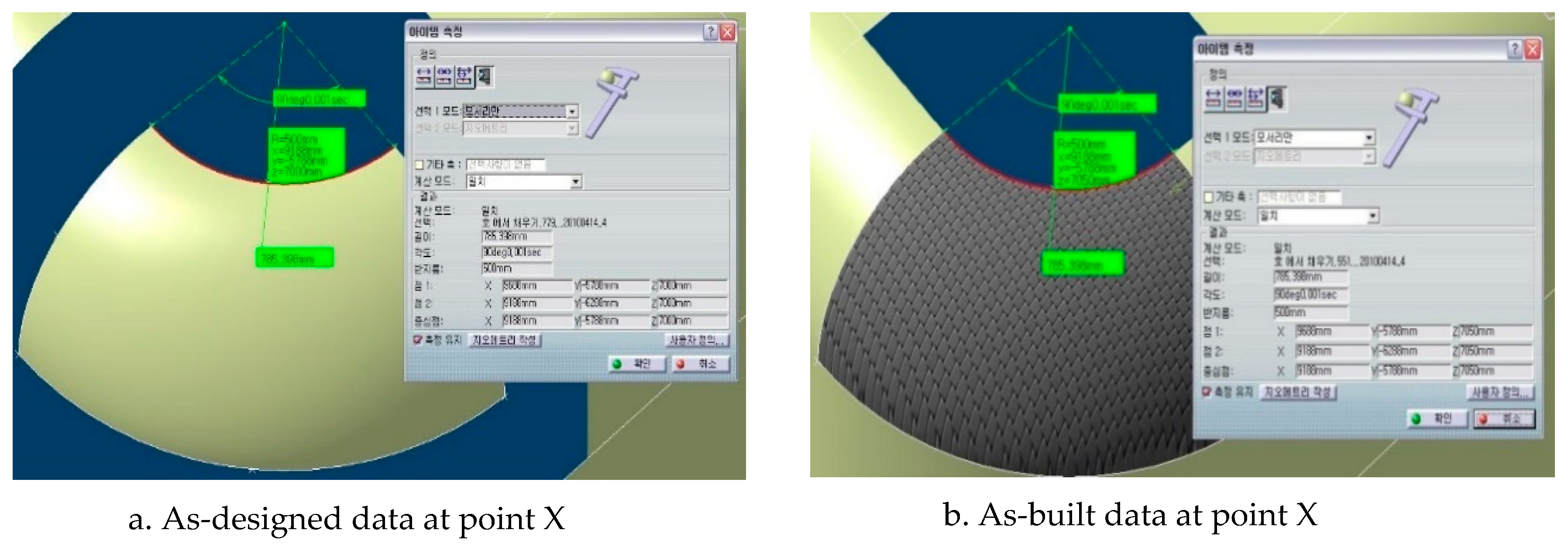
3.1. As-Designed Data
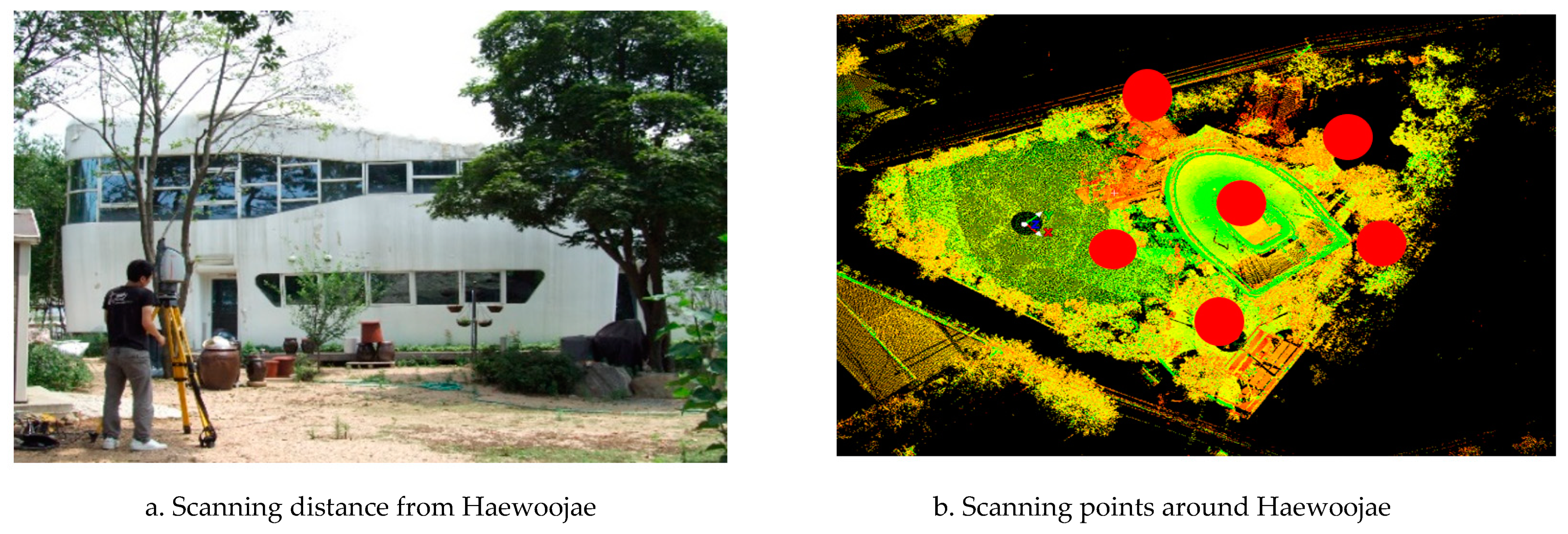
3.2. As-Built Data
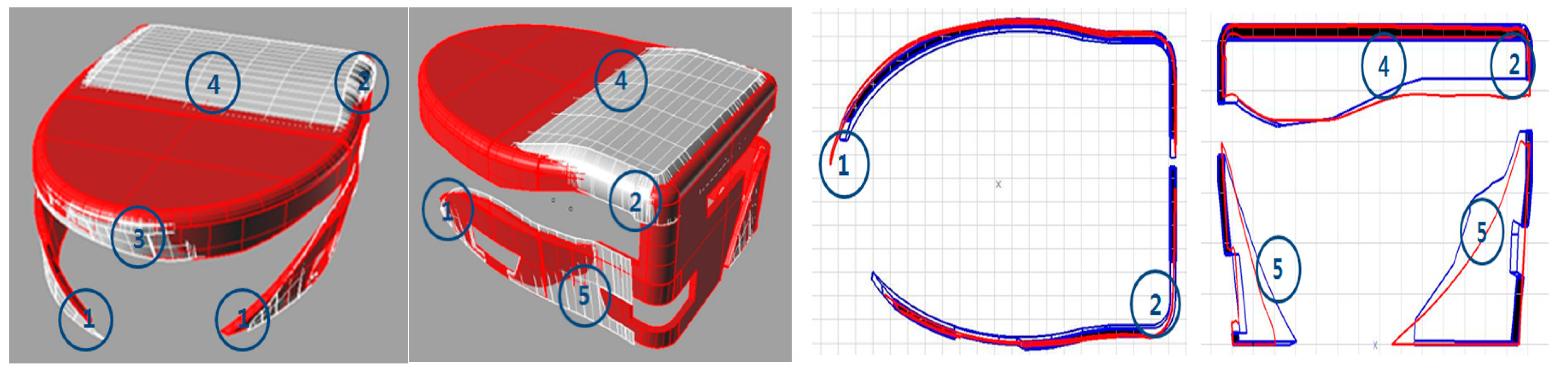
3.3. Superimposed Data Comparison
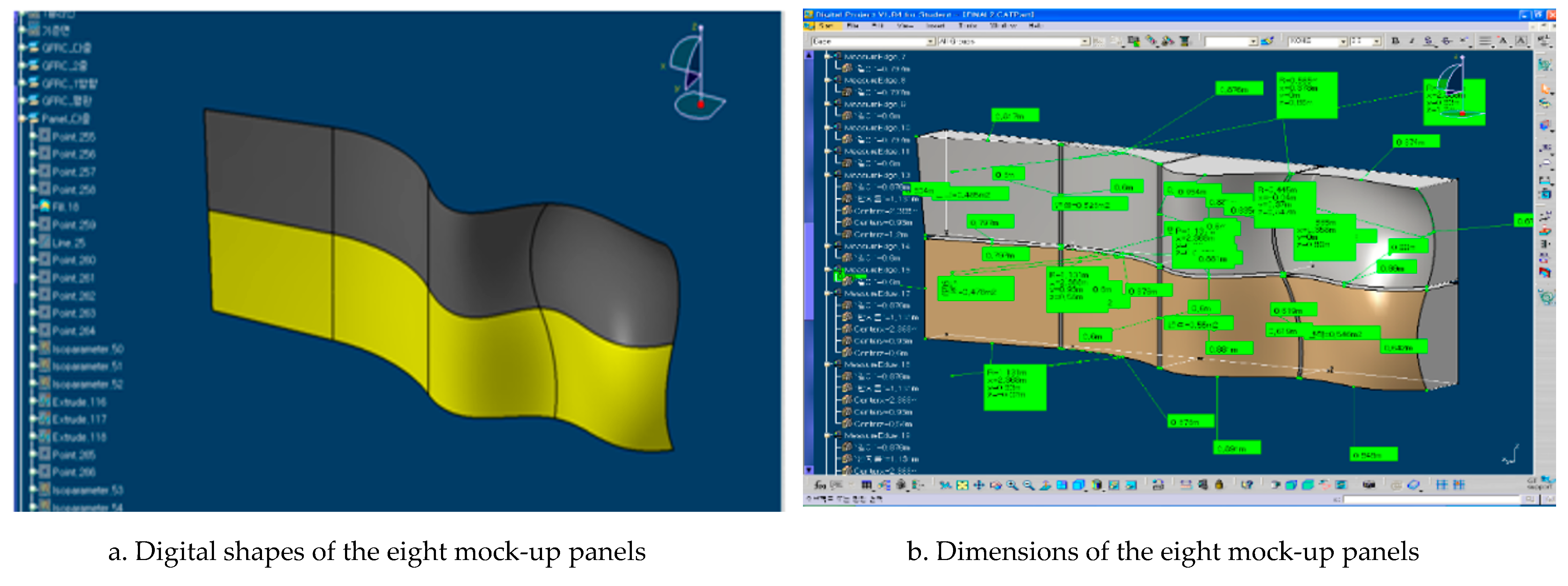
4. Mock-up Fabrication
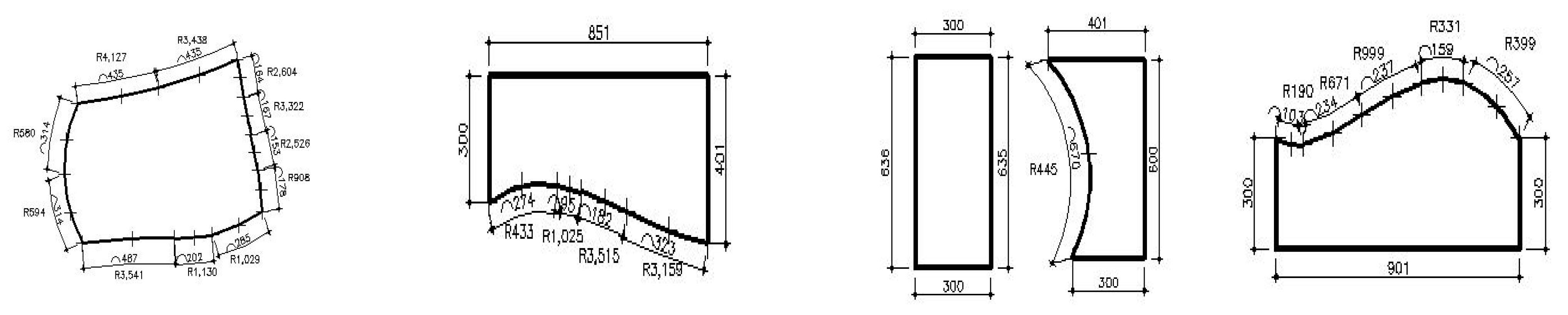
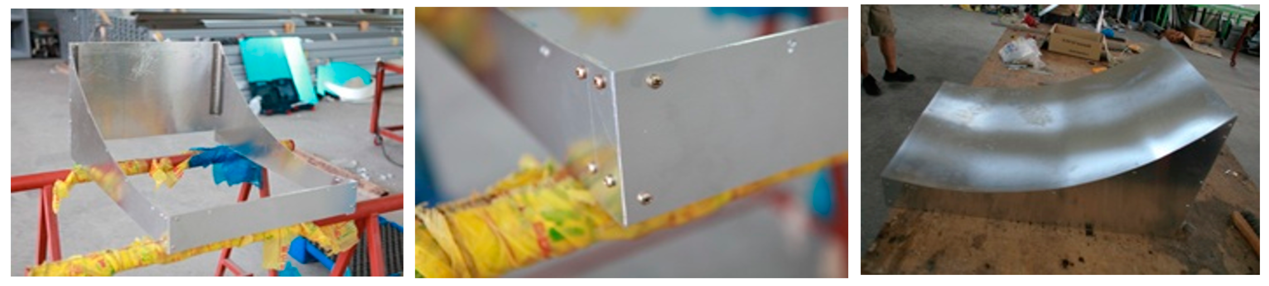
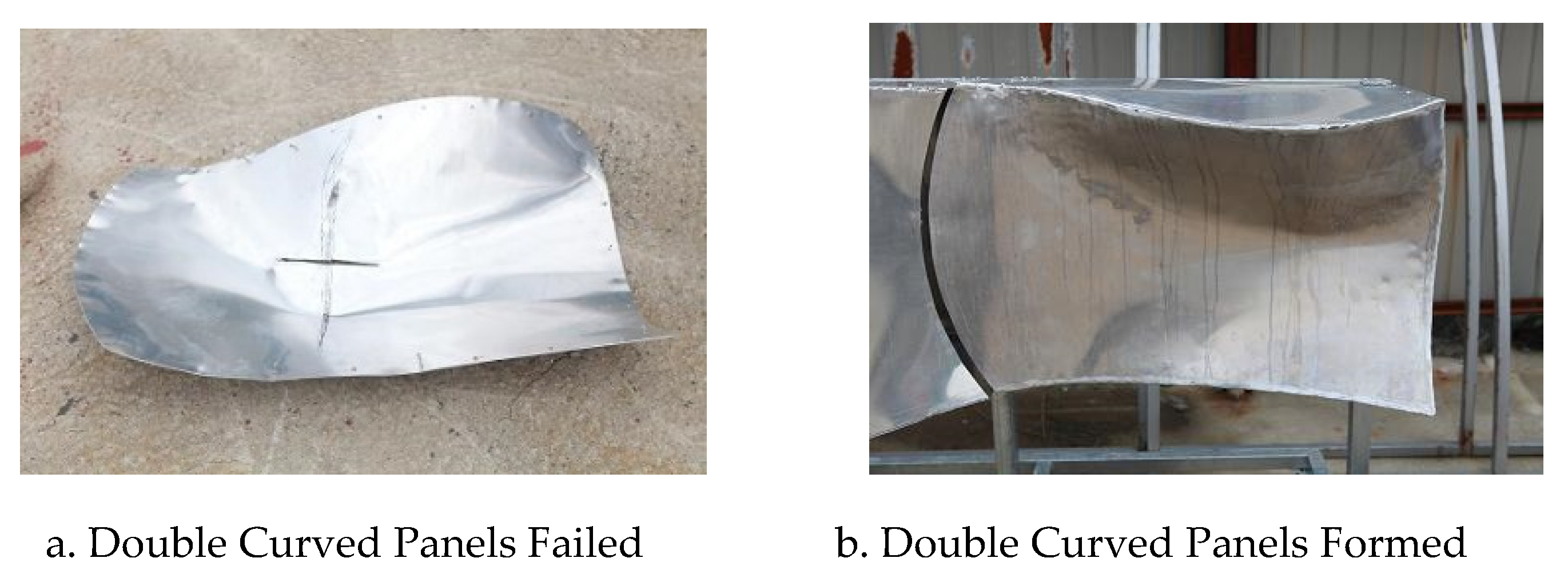
4.1. Aluminum Mock-up Panel Production
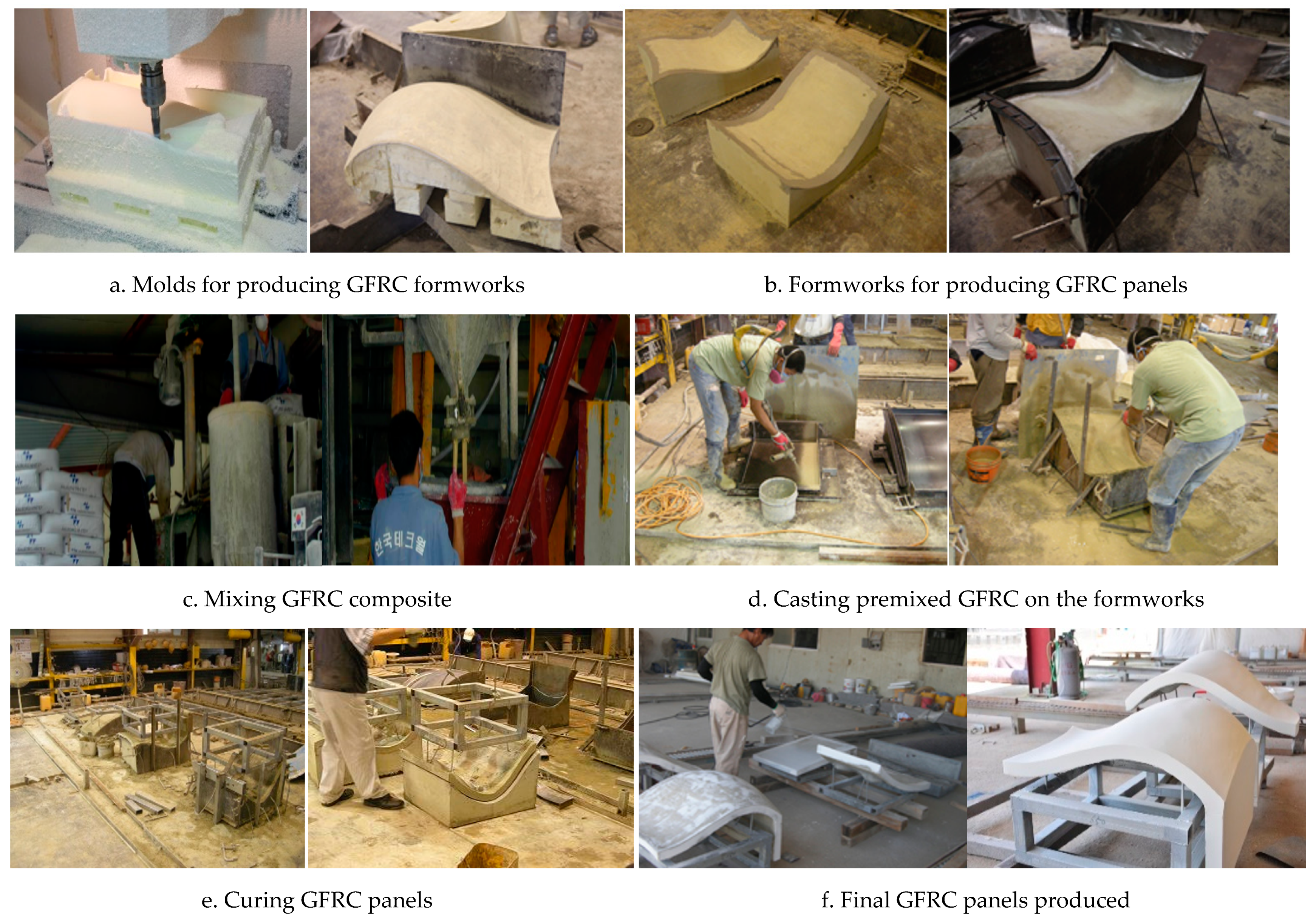
4.2. GFRC Mock-up Panel Production
4.3. Mock-Up Data Analysis
5. Lessons Learned and Limits
5.1. Lessons Learned
5.2. Limits
6. Conclusions
Funding
Institutional Review Board Statement
Informed Consent Statement
Data Availability Statement
Acknowledgments
Conflicts of Interest
References
- Kim, S.W. Classification and Optimization of Irregular Shaped Building Panels by Fabrication Methods: Focused on Dondaemun Design Plaza and Park. Master’s Thesis, Yonsei University, Seoul, Korea, 2009. [Google Scholar]
- Piegl, L.A.; Tiller, W. Biarc approximation of NURBS curves. Comput. Aided Des. 2002, 11, 807–814. [Google Scholar] [CrossRef]
- Park, H.K.; Ock, J.H. Developing the Preliminary Cost Estimate for the Free-Form Building Façade in Conjunction with the Panel Optimization Process. KSCE J. Civ. Eng. 2015, 5, 1214–1223. [Google Scholar] [CrossRef]
- Sheldon, D.R. Digital Surface Representation and the Constructability of Gehry’s Architecture. Ph.D. Thesis, Massachusetts Institute of Technology, Boston, MA, USA, 2002. [Google Scholar]
- Kwen, S.H.; Shim, H.W.; Ock, J.H. A Study on the Problem Analysis and Quality Improvement in Fabricating Free-form Buildings’ Façade Panels through Mock-up Panels Production. J. Korean Inst. Constr. Eng. Manag. 2011, 3, 11–21. [Google Scholar]
- Kwen, S.H.; Shim, H.W.; Jang, H.S.; Ock, J.H. A Fundamental Study on the Comparison of As-Planned with As-Built of Free-form Building Skins Using Laser Scanning Technology. J. Comput. Des. Eng. 2011, 2, 126–136. [Google Scholar]
- Lee, G.; Kim, S.W. Case study of mass customization of double curved metal façade panels using a new hybrid sheet metal processing Technique. J. Constr. Eng. Manag. 2012, 11, 1322–1330. [Google Scholar] [CrossRef]
- Buswell, R.A.; Soar, R.C.; Gibb, A.G.F.; Thrope, A. Freeform Construction: Mega-scale Rapid Manufacturing for Construction. Autom. Constr. 2007, 16, 224–231. [Google Scholar] [CrossRef] [Green Version]
- Ock, J.H. Assessing Suitability of the Cold Bending Method in Fabricating Free-form Façade Panels. Civ. Eng. Res. J. 2018, 1, 17–27. [Google Scholar]
- Kavuma, A.; Ock, J.H.; Jang, H.S. Factors Influencing Time and Cost Overruns on Freeform Construction Projects. KSCE J. Civ. Eng. 2017, 4, 1442–1450. [Google Scholar] [CrossRef]
- Buswell, R.A.; Thrope, A.; Soar, R.C.; Gibb, A.G.F. Design, Data, and Process Issues for Mega-Scale Rapid Manufacturing Machines used for Construction. Autom. Constr. 2008, 17, 923–929. [Google Scholar] [CrossRef] [Green Version]
- Saranguimoim. “Suwon Haewoojae (Toilet Museum).” Posted on 16 February 2016. Available online: http://blog.daum.net/qhdlf9090/513 (accessed on 3 June 2016).
- Schodek, D.; Bechthold, M.; Kao, K.M.; Steinberg, M. Digital Design and Manufacturing-CAD/CAM Applications in Architecture and Design; Wiley: Hoboken, NJ, USA, 2005. [Google Scholar]
- Eekhout, M.; Barbara, G.; Walter, L. Free Form Technology from Delft; Research in Architectural Engineering Series; IOS Press: Amsterdam, The Netherlands, 2015. [Google Scholar]
- Eigensatz, M. Case Studies in Cost-Optimized Paneling of Architectural Freeform Surfaces, Advances in Architectural Geometry; McGraw-Hill: New York, NY, USA, 2010. [Google Scholar]
- Ryu, H.G.; Kim, S.J. Case Study of Concrete Surface Design and Construction Method for Freeform Building based on BIM—Focused on Tri-Bowl, Korea. J. Korea Inst. Build. Constr. 2012, 3, 347–357. [Google Scholar] [CrossRef] [Green Version]
- Ock, J.H. A Study on the Development of Digital Contents and Advertisement of Design Seoul Freeform Buildings. In Intermediate Report of New Technology Research and Development; Seoul National University of Science and Technology: Seoul, Korea, 2010. [Google Scholar]
- Suchy, I. Bending and Forming Operations. In Handbook of Die Design, 2nd ed.; McGraw-Hill Publishers: New York, NY, USA, 1998. [Google Scholar]
- Gleason, D. Laser Scanning for an Integrated BIM. In Proceedings of the Lake Constance 5D Conference, Constance, Germany, 28–29 October 2013. [Google Scholar]
- Shin, N.J.; Huang, S.T. 3D Scan Information Management System for Construction Management. J. Constr. Eng. Manag. 2006, 2, 134–142. [Google Scholar]
- Su, Y.Y.; Hashash, Y.M.A.; Liu, L.Y. Integration of Construction As-built Data via Laser Scanning with Geotechnical Monitoring of Urban Excavation. J. Constr. Eng. Manag. 2006, 12, 1234–1241. [Google Scholar] [CrossRef]
- Park, J.S.; Pyeon, M.U.; Jo, J.H.; Lee, G.H. Case Study of Civil-BIM & 3D Geographical Information. Korean J. Land Surv. 2011, 6, 569–576. [Google Scholar]
- Shanbari, H.A.; Blinn, N.M.; Issa, R.R. Laser Scanning Technology and BIM in Construction Management in Education. J. Inf. Technol. Constr. 2016, 21, 204–217. [Google Scholar]
- Ratajczak, J.; Marcher, C.; Schimanski, C.P.; Schweigkofler, A.; Riedl, M.; Matt, D. BIM-based Augmented Reality Tool for the Monitoring of Construction Performance and Progress. In Proceedings of the 2019 European Conference on Computing in Construction, Crete, Greece, 10–12 July 2019; pp. 467–490. [Google Scholar]
- Raimbaud, P.; Lou, R.; Merienne, F.; Danglade, F.; Figueroa, P.; Hernandez, J.T. BIM-based Mixed Reality Application for Supervision of Construction. In Proceedings of the IEEE Conference on Virtual Reality and 3D User Interfaces (VR), Osaka, Japan, 23–27 March 2019; pp. 1903–1907. [Google Scholar]
- Lim, J.S.; Ock, J.H. A Pilot study on the Development of an Augmented Reality-based Decision Support System for Free-Form Buildings Construction management. Trans. Soc. Eng. 2012, 3, 175–187. [Google Scholar]
- Kim, S.C.; Eom, S.J. Free-form External Design using BIM and Development of Grasshopper Model. Int. J. Eng. Technol. 2018, 7, 146–152. [Google Scholar]
- Eastman, C.; Teicholz, P. Building Information Modeling Handbook; Wiley John & Sons: Hoboken, NJ, USA, 2009. [Google Scholar]
- Boehler, W.; Marbs, A. 3D Scanning instruments. In Proceedings of the CIPA WG 6 International Workshop on Scanning for Cultural Heritage Recording, Ziti, Thessaloniki, 1–2 September 2002. [Google Scholar]
- Alonso, S.H.; Rubio, J.I.M.; Martin, J.F.; Fernandez, J.J.G. Comparing Time-of-Flight and Phase Shift. The Survey of the Royal Pantheon in the Basilica of San Isidoro. International Archives of the Photogrammetry, Remote Sensing and Spatial Information Sciences, 38-5/W16. In Proceedings of the ISPRS Trento 2011 Workshop, Trento, Italy, 2–4 March 2011; pp. 377–385. [Google Scholar]
- Richard, M.C. Physical Ductility of the Elements, Failurecriteria.com, Updated 11 January 2016. Available online: http://www.failurecriteria.com/physicalductilit.html (accessed on 5 June 2016).
- Ferreira, J.P.J.G.; Brance, F.A.B. The Use of Glass Fiber-Reinforced Concrete as a Structural Material. Exp. Tech. 2007, 31, 64–72. [Google Scholar] [CrossRef]
- Countertop Institute. Glass Fibers—An Essential Component of GFRC Concrete Countertops. November 2020. Available online: http://www.concretecountertopinstitute.com/free-training/glass-fibers-an-essential-component-of-gfrc-concrete-countertops (accessed on 25 November 2020).


| Difference Contents | Panel Types | |
|---|---|---|
| 1 | Panel finishing location Panel length | single-curved panels |
| 2 | Panel connection position Panel size Panel curvature size and shape | double-curved panels |
| 3 | Panel curvature starting point Panel size Panel curvature size and shape | double-curved panels |
| 4 | Panel slope degree | single-curved panels |
| 5 | Panel size Panel connection position | single-curved panels |
| (a) Coordinate Values of the As-Designed Model | (b) Coordinate Values of the As-Built Model | ||||||
|---|---|---|---|---|---|---|---|
| X | Y | Z | X | Y | Z | ||
| mm | mm | mm | Mm | mm | mm | ||
| Surface C | Aluminum Panel | Surface C | Aluminum Panel | ||||
| C point 1 | 1580 | 100 | 1200 | C point 1 | 1593 | 103 | 1205 |
| C point 2 | 830 | 0 | 1200 | C point 2 | 880 | −3 | 1197 |
| C point 3 | 880 | 0 | 600 | C point 3 | 863 | −5 | 595 |
| C point 4 | 1580 | 100 | 600 | C point 4 | 1590 | 102 | 592 |
| Surface C-1 | GFRC Panel | Surface C-1 | GFRC Panel | ||||
| C-1 point 1 | 1580 | 100 | 580 | C-1 point 1 | 1584 | 101 | 576 |
| C-1 point 2 | 880 | 0 | 580 | C-1 point 2 | 878 | 0 | 581 |
| C-1 point 3 | 780 | 0 | −20 | C-1 point 3 | 781 | 0 | −17 |
| C-1 point 4 | 1580 | 100 | −20 | C-1 point 4 | 1578 | 98 | −18 |
| Location | X Direction Discrepancy | Y Direction Discrepancy | Z Direction Discrepancy |
|---|---|---|---|
| Point 1 | 13 mm | 3 mm | 5 mm |
| Point 2 | 50 mm | 3 mm | 3 mm |
| Point 3 | 17 mm | 5 mm | 5 mm |
| Point 4 | 10 mm | 2 mm | 8 mm |
| Materials | Edges, Diagonals | As-Designed Length (mm) | As-Built Length (mm) | Discrepancy (mm) |
|---|---|---|---|---|
| Aluminum, Panel (C) | P1 ~ P2 | 756.6 | 720.9 | −35.7 |
| P2 ~ P3 | 602.1 | 602.2 | 0 | |
| P3 ~ P4 | 707.1 | 734.7 | 27.6 | |
| P4 ~ P1 | 600 | 613 | 13 | |
| P1 ~ P3 | 927.4 | 957.4 | 30 | |
| P2 ~ P4 | 965.7 | 938.7 | −27 | |
| GFRC, Panel (C-1) | P1 ~ P2 | 707.1 | 713.2 | 6.1 |
| P2 ~ P3 | 608.3 | 605.8 | −2.5 | |
| P3 ~ P4 | 806.2 | 803 | −3.2 | |
| P4 ~ P1 | 600 | 594 | −6 | |
| P1 ~ P3 | 1005 | 1003.32 | −1.7 | |
| P2 ~ P4 | 927.4 | 926.5 | −0.9 |
| Dimension Range (mm) | Length (L), Width (W) (mm) | Diagonal (mm) | Bending |
|---|---|---|---|
| W, L < 1500 | ±1.5 | ±2.0 | 1 mm per 1 m |
| 1500 ≤ W, L < 4000 | ±2.0 | ±3.0 |
Publisher’s Note: MDPI stays neutral with regard to jurisdictional claims in published maps and institutional affiliations. |
© 2021 by the author. Licensee MDPI, Basel, Switzerland. This article is an open access article distributed under the terms and conditions of the Creative Commons Attribution (CC BY) license (http://creativecommons.org/licenses/by/4.0/).
Share and Cite
Ock, J.-H. Testing as-Built Quality of Free-Form Panels: Lessons Learned from a Case Study and Mock-up Panel Tests. Appl. Sci. 2021, 11, 1439. https://doi.org/10.3390/app11041439
Ock J-H. Testing as-Built Quality of Free-Form Panels: Lessons Learned from a Case Study and Mock-up Panel Tests. Applied Sciences. 2021; 11(4):1439. https://doi.org/10.3390/app11041439
Chicago/Turabian StyleOck, Jong-Ho. 2021. "Testing as-Built Quality of Free-Form Panels: Lessons Learned from a Case Study and Mock-up Panel Tests" Applied Sciences 11, no. 4: 1439. https://doi.org/10.3390/app11041439