Abstract
In this study, multi-story structures with different combinations (on each floor and only the first floor) of active tendon control systems driven by a proportional–integral–derivative (PID) controller were actively controlled. The PID parameters, Kp (proportional gain), Td (derivative gain), and Ti (integral gain) for each structure, were optimally tuned by using both the harmony search algorithm (HS) and flower pollination algorithm (FPA), which are metaheuristic algorithms. In two different active-controlled structures, which are formed according to the position of the PID, the structural responses under near-fault records defined in FEMA P-695 are examined to determine the appropriate feedback which was applied for displacement, velocity, acceleration, and total acceleration. The performance of the different feedback strategies on these two active-controlled structures is evaluated. As a result, the acceleration feedback is suitable for all combinations of the active control system with a PID controller. The HS algorithm outperforms the optimum results found according to the FPA.
1. Introduction
Different control systems have been used in structures for many years to reduce the structural responses due to dynamic loads such as earthquakes and wind, which can cause destructive and permanent damage to the structures. These control systems are applied in various forms of passive, semi-active, and active, depending on the properties of the structure and the dynamic effect. It is known that active control systems absorb more energy than other control systems. The main reason for high energy absorption is the placement of actuators that generate the control force in every step of the seismic excitation. Generally, the use of active control systems in the structures can be provided in two different ways. The first way is the usage of an active tendon system applied on the first or each floor of the structures. The other way is the implementation of an active mass damper placed on the top floor of the structures. In the research, the active tendon control is examined. The actuators, which create the control force to absorb the energy in the structure according to the value determined by the sensors, are cross-linked to the pre-stressed tendons to realize active tendon control.
The idea about the active control of structures was first introduced by Zuk [1] and was subsequently expanded with analytical or experimental studies. The utilization of active mass dampers and active tendons to reduce structural reactions in tall structures [2,3], the relationship between the control forces and the structural responses [4], time delay effect [5], and the investigation of various feedback strategies for active-controlled structures [6,7] can be examples among these studies. In addition, many studies are available in the literature either to determine the parameters of various control techniques such as H2, Hinf, linear quadratic regulator (LOR), neural network control, fuzzy logic control, sliding mode control (SMC) and proportional–integral–derivative (PID) controller or to improve the weaknesses of these techniques by comparing them with each other. For instance, a proposal of an instantaneous optimal control algorithm with a modification to reduce the time delay effect [5] was proposed. The attainment of effective solutions in the nonlinear active-controlled structures with artificial neural networks and the use of the metaheuristic algorithms to calculate the parameters of the PID, H2, and Hinf are the other stochastic based methods in the active control [8,9,10]. The utilization of a modified linear quadratic regulator (MLQR) was investigated to determine the degree of the system stability before the earthquake [11]. The prevention of the chattering effect with the help of a fuzzy sliding-mode control algorithm [12] was studied by Alli and Yakut. The determination of the PID parameters with a numerical algorithm [13] was conducted by Nigdeli and Boduroglu for the control of irregular structures. The analysis of nonlinear active-controlled structures was carried out by combining a dynamic fuzzy wavelet neural emulator and the floating-point genetic algorithm [14]. The use of neural-based sliding-mode control with genetic algorithms was developed by Yakut and Alli [15]. The comparison of the sliding mode controller without a chattering problem with PID was performed by Guclu [16]. The comparison of the block pulse functions with the linear quadratic regulator was proposed by Ghaffarzadeh and Younespour [17]. The comparison of a wavelet-based adaptive pole assignment with the linear quadratic regulator was proposed and the system was optimized via active tuned mass dampers via metaheuristics [18].
The conventional mathematical methods are sufficient to overcome some engineering problems. However, the traditional methods can cause both a loss of time and an increase in the error rate when it comes to solving some complex engineering problems. Therefore, the algorithms which contain the mathematical expressions are needed to achieve successful results in the appropriate time frame. Among the algorithms used as solution methods are metaheuristic algorithms. The inspiration of metaheuristic algorithms is based on the instinctive behaviors which exist in nature. The harmony search algorithm, inspired by the musician who plays their top notes to satisfy their audience [19], and the flower pollination algorithm, which is inspired by flower pollination, are two important representatives of metaheuristic algorithms [20]. Each metaheuristic algorithm has properties other than the random selection of the design variables and their own finding of the best solution to the objective function.
The two different cases of the active tendon-controlled structures, which are Case 1 (control only on the first floor and Case 2 (control on each floor), were investigated under near-fault ground motions, which include two impulsive motions called the flint step and directivity effect. The time delay effect is considered in all systems with different feedback strategies such as displacement, velocity, acceleration, and total acceleration. The aim is to calculate the optimal parameters for a limited control force so that it does not exceed 10% of the total weight of the structure. Both the harmony search algorithm (HS) and flower pollination algorithm (FPA) are used to determine PID parameters. The optimum results of both are quite close. As a result, it was determined that the different feedback control strategies vary the structural responses where active control provides differently. The use of both HS and FPA is suitable for the fast and successful detection of a correct feedback strategy during the design phase of the structures.
2. The Proposed Methodology
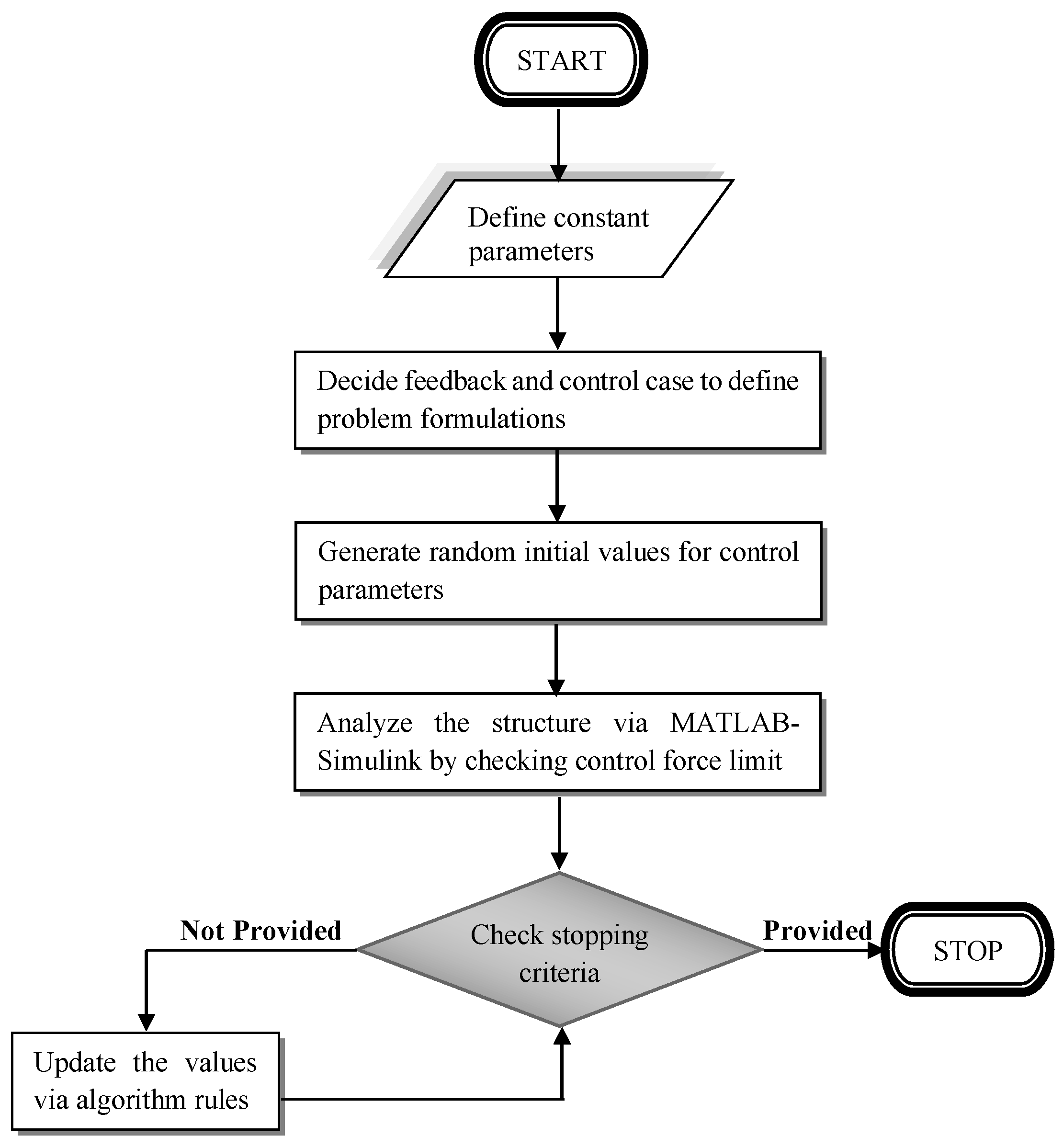
The methodology is summarized in the flowchart given in Figure 1. In general speaking, the proposed method combines the iterative analysis of the dynamic analysis of the structure with an employed optimization methodology.
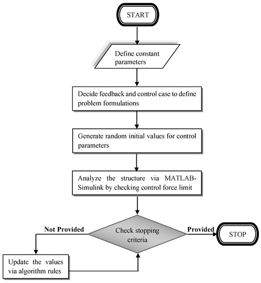
Figure 1.
The flowchart diagram general methodology.
In the first step, the process starts with the definition of the constant parameters of the problem. These parameters include structural parameters such as mass, stiffness, and damping. In addition, the constant parameters related to optimization such as ranges of controller parameters (proportional gain, derivative gain and integral gain) that are optimized, algorithm-specific parameters (harmony memory size, harmony memory considering rate, pitch adjusting rate, switch probability and population number) and the iteration number are defined. In addition to that, the ground acceleration record given in Section 3 is checked for the responses of the method and is also defined.
In the second step, the formulations defining the control system are provided for several different feedbacks like displacement, velocity, acceleration and total acceleration and many cases of the orientation of the control system. In this paper, four feedback control strategies using PID controllers and two orientations of active tendon control systems were investigated.
In the third step, a solution set vector is created using control and algorithm-specific parameters. Moreover, the objective function calculated as a result of these parameters is stored in this solution set vector. The number of solution set vectors is equal to the population number (harmony memory size in HS). All these vectors form the initial solution set matrix.
By using these feedback control strategies and orientation cases, the analysis of the actively controlled structure was performed for the time history analysis using the generated MATLAB Simulink [21] model that also includes the consideration of the delay of the control signal and a stopping factor that prevents the stability error and helps with shortening the processing time via comparing the displacements of the controlled system during the time-domain with the maximum response of the structure without control. In this analysis, randomly selected design variables defined as the controller parameters are used. All design variables and the corresponding maximum analysis result taken as the objective function (the same as the feedback used in the generation of the control signal) are saved. The aim of the control and optimization is to reduce the first story responses, and it is the same for the responses and feedback used for error signals in controllers. This value is penalized with a big value if the maximum control force exceeds the maximum allowed limit.
Then, the initially generated solution sets are updated via the rules and formulations of the metaheuristic algorithms explained in the following subsections. The updated design variables and the corresponding results modified via the selected algorithm are saved instead of the existing ones if it is better in performance in the reduction in the considered analysis result as the objective function of the problem. This study involves the presentation and application of two metaheuristic algorithms (HS and FPA) for the comparison of the results. The update process of the solutions continues for a maximum number of iterations.
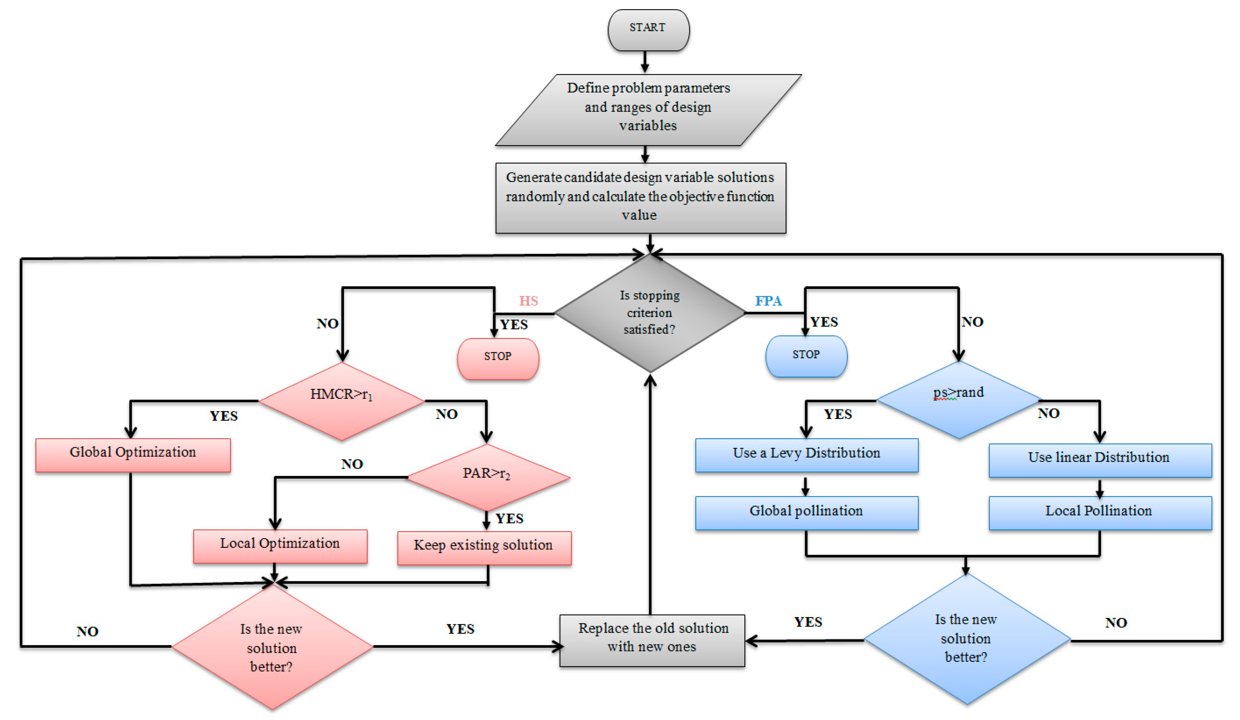
In the following Section, the mathematical expression of both HS and FPA with the flow diagram are given in Figure 2, and the working principle of the PID controller, the characteristics of the near-fault ground motion, and the optimization process of the structures under the near-fault ground motions defined in FEMA P-695: Quantification of Building Seismic Performance Factors [22] (In Quantification of Building Seismic Performance Factors; Federal Emergency Management Agency: Washington, DC, USA, 2009. WAITDELETE), are discussed.

Figure 2.
The flowchart diagram of harmony search and flower pollination algorithms.
2.1. Harmony Search Algorithm
A musician achieves the best musical work by gradually improving the harmony of the notes in their works to satisfy the audience. The HS algorithm is a music-inspired metaheuristic algorithm developed by Geem et al. [19] to determine the best result of the optimization problems as the creation of the best musical performance. In this algorithm, the musician performs three different efforts to prepare their works, namely:
- Playing notes of any popular musical performance in their memory;
- Playing new notes similar to the notes of a known musical performance;
- Playing completely different notes.
The HS algorithm includes two parameters: the harmony memory considering rate (HMCR) and the pitch adjusting rate (PAR) to prevent trapping to a local optimum. HMCR is the probability of calculating a new value close to the existing values. PAR is the ratio of the shrinking solution range to the entire solution range. The values of HMRC and PAR vary between 0 and 1 in the optimization process. The equations of the harmony search algorithm are as follows:
is the newly generated ith solution for (t + 1)th iteration, and are the max and min limit of design variables, rand(0,1) is a random number between 0 and 1, is the randomly chosen existing solution, ni is the neighborhood index, bw is an arbitrary distance bandwidth, r1 and r2 are the random numbers between 0 and 1, and r3 is the random number between 1 and −1.
2.2. Flower Pollination Algorithm
FPA is a metaheuristic algorithm inspired by the pollination of flowers and it was developed by Yang [20]. In the algorithm, the types of pollination (self-pollination in local optimization and cross-pollination in global optimization) and the continuous reiteration of the visit to the same flower of the pollinator are quite important in optimization processes. The steady repetition of the visit to the same flower of the pollinator is provided to put the pollen in the most accurate flower. In addition, the consideration of Levy flights and the determination of a switch probability that is a specific parameter to choose the pollination type play an important role in the global pollination process to tolerate local pollination. Mathematical expressions of global pollination and local pollination are given in Equations (5) and (6), respectively:
L is Levy distribution, g* is the best existing solution, is the existing solution for the ith iteration, ε is the linear distribution, and is a randomly chosen existing solution.
2.3. PID (Proportional–Integral–Derivative) Controllers
The responses of the first floor of structures such as displacement, velocity, acceleration, and total acceleration are considered as the feedback (x) and the error signal (e(t)) is found according to the reference signal (xr), which is taken as zero. After the determination of the error signal (Equation (7)) for each step of an earthquake, the control signal using Equation (8) is calculated. The final equation of the control signal of the nth floor (un) is given in Equation (9). The design variables are the PID controller parameters such as Kp (proportional gain), Td (derivative gain), and Ti (integral gain):
2.4. Near-Fault Ground Motions
Near-fault ground motions, which are 15 km away from the fault rupture, are different from far fault ground motions because of the impulsive characteristic such as the permanent ground displacement and high peak ground acceleration and velocity [23]. Therefore, the structures under near-fault ground motions need more ductility to prevent its destructive effects. The near-fault ground motion without pulse and the near-fault ground motions with pulse defined in FEMA P-695 are given in Table 1 and Table 2, respectively. These records were downloaded by the Pacific Earthquake Engineering Research Center (PEER NGA DATABASE) [24] and both horizontal components of the records were used in this study. These records have two components called the flint step effect, which causes permanent ground displacement, and the directivity effect, which has the long-period pulse.

Table 1.
The near-fault ground motions without a pulse.
Table 2.
The near-fault ground motions with a pulse.
2.5. The Equation of Motion of Active-Controlled Structures
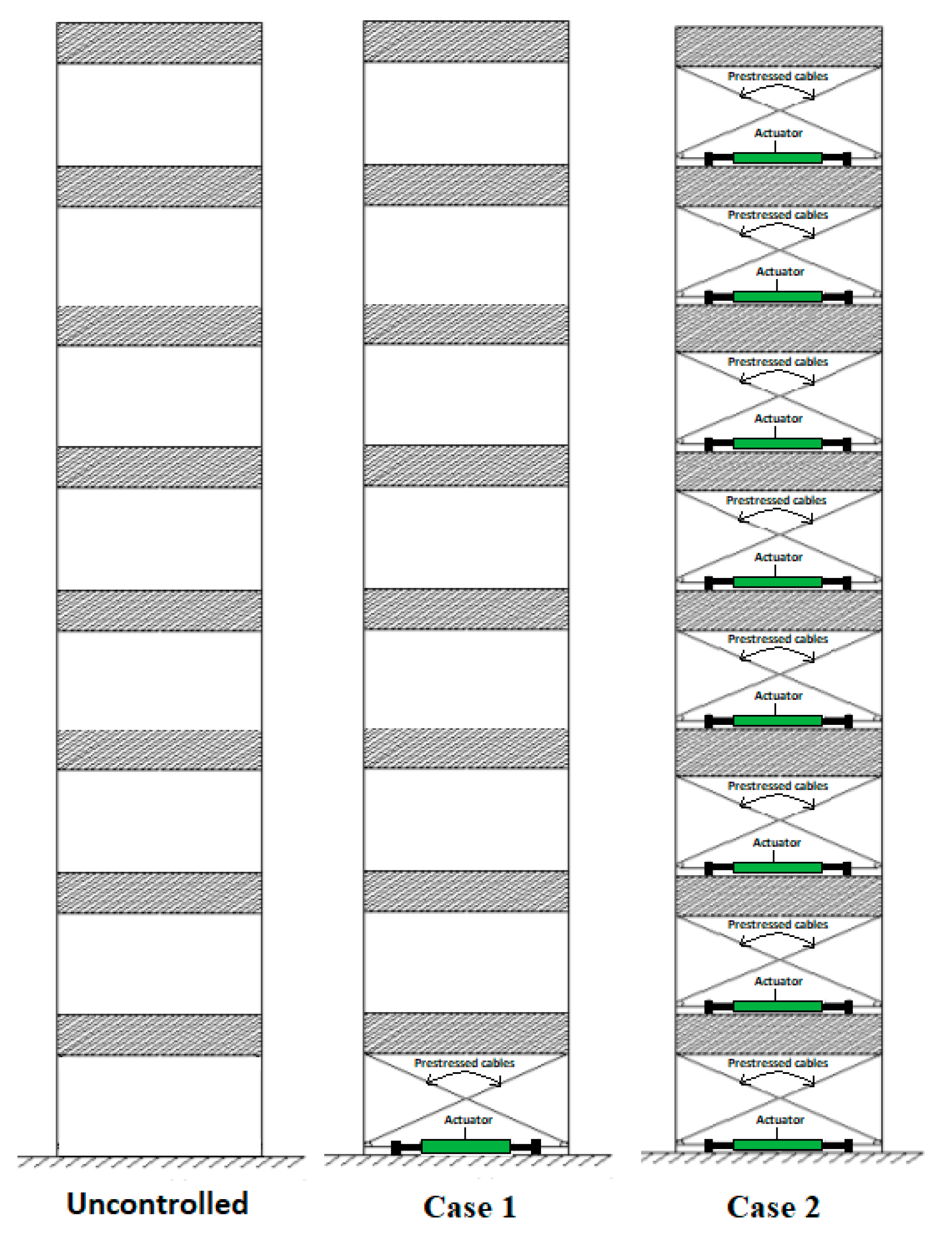
Two different active-controlled structures are shown in Figure 3. In Case 1, the active control is placed only on the first floor. The structural responses such as displacement, velocity, acceleration, and total acceleration on the first floor are measured with a sensor according to the desired feedback to calculate the control signal and the corresponding control force which is applied to the first floor. In Case 2, the reactions of the control forces occur in the lower floor of the control force applied floor. In that case, the control force is reduced with the force of the upper story for this floor. For that reason, the control forces must be increased for the lower floors to provide an effective control force that is reduced by the opposite control force. In the present study, the control signal is calculated according to the responses of the first floor as in the first case and these forces must be factored with (n + i + 1) for the ith story of the n-storied structure to provide control forces that are evenly distributed to all floors as the same value. For that reason, the active control system must be applied for all stories or all control forces must be supported by the ground. In the literature, multi-story control system orientations that are supported by the ground also exist, but it is not a feasible case for a high structure since the horizontal control force will reduce while the vertical component of the force is increasing, which needs the direct increase in prestress force on the cable [7].

Figure 3.
A sample model (n = 8) for the uncontrolled shear structure and the cases for active-controlled structures.
The equation of motion of the active tendon-controlled structures (Case 1 and Case 2) is given in Equation 10. Here, [M] is the mass matrix, [C] is the damping matrix, [K] is the stiffness matrix, Kc is the stiffness of the tendon, α is the angle of the tendon, 1 is the unit vector, b is the influence vector of the control force and ag(t) is the ground acceleration. In addition, a(t), v(t) and x(t) represent the acceleration, velocity and displacement, respectively. These matrices and vectors are shown as Equations (11)–(19) for an n degree of freedom shear structure:
[M]a(t) + [C]v(t) + [K]x(t) = −[M]1ag − (4kccosα)b
2.6. The Dynamic Analysis of the Controlled Structures
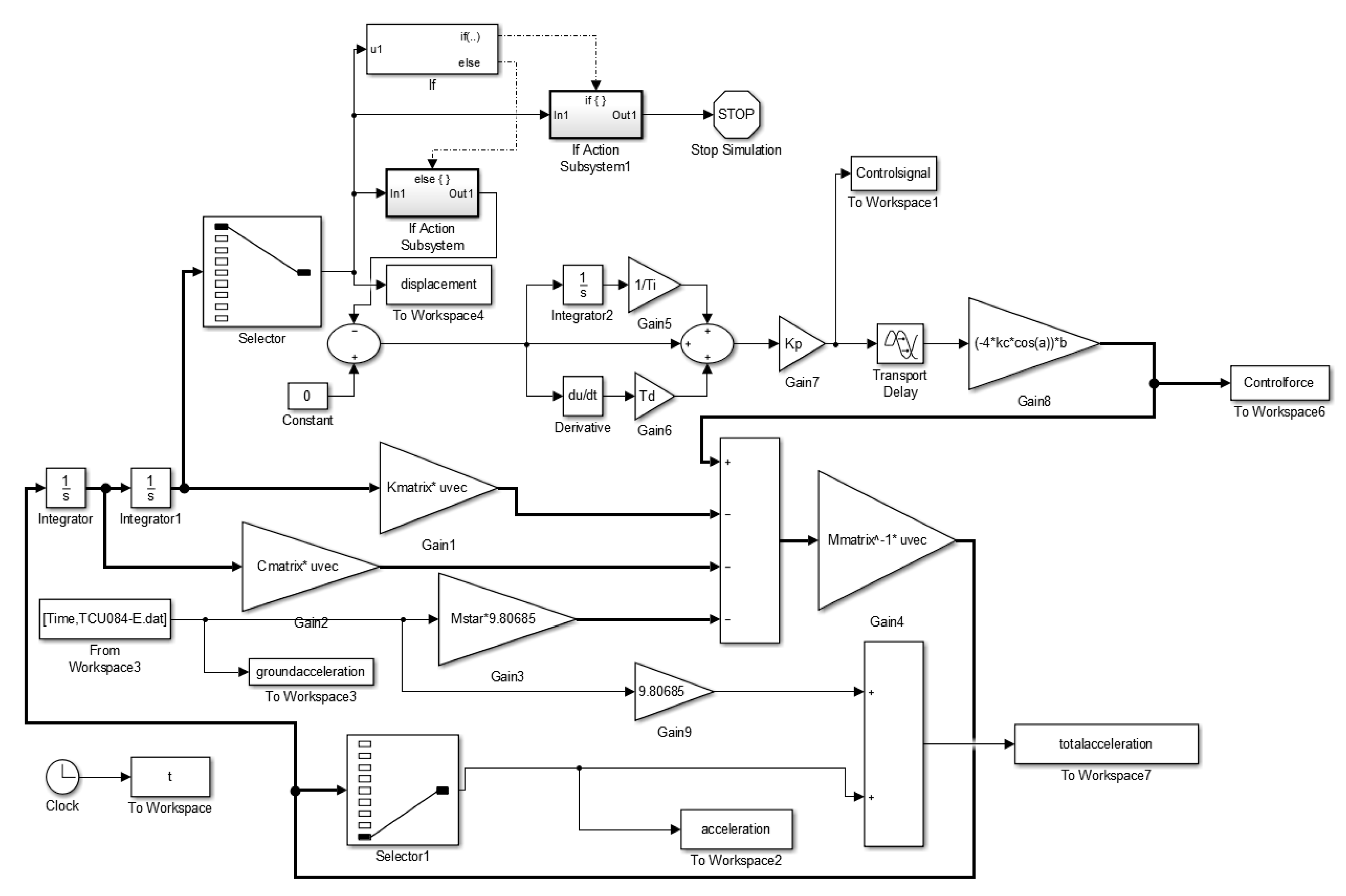
The optimization code including the mathematical expressions of metaheuristic algorithms optimizing the design variables and minimizing the objective function taken as the performance index of control (displacement, velocity, acceleration, and total acceleration for the corresponding feedbacks) was written in MATLAB [21]. The dynamic analysis concerning the design constraint such as the control limit coupled with the numerical solution of the differential equation of motion is done via Simulink, which is the subprogram of MATLAB [21]. The maximum iteration number was taken as 10,000, the time delay of the controller was taken as 20 ms and the simulation time of the dynamic analyses was taken as 120 s. In addition, the Runge–Kutta Method with time step h = 0.001 is used to solve the differential equation. The block diagram of active-controlled structures with displacement feedback is given in Figure 4. The response vector is connected to a selector block to select the first story responses in the generation of the control signal. In acceleration and velocity feedbacks, the connecting signal vector is changed. The responses of each time lap are checked via an “if” block in MATLAB Simulink to realize the stability problem by controlling the large increase in displacements. The allowed limit of the displacement is the maximum value of the displacement for the uncontrolled structure. Additionally, it skips the unnecessary dynamic analysis process to save computational time. If the controlled response of a time lap is more than the maximum response under the critical excitation, the simulation is stopped.

Figure 4.
The block diagram of the active-controlled structures with displacement Figure 3. Numerical examples.
3. Numerical Examples
The mass, stiffness, and damping coefficients of an eight-story shear building [25] are given in Table 3. In both cases, the stiffness and the angle of the tendons are 36° and 372,100 N/m, respectively [8].
Table 3.
The story properties of the structure.
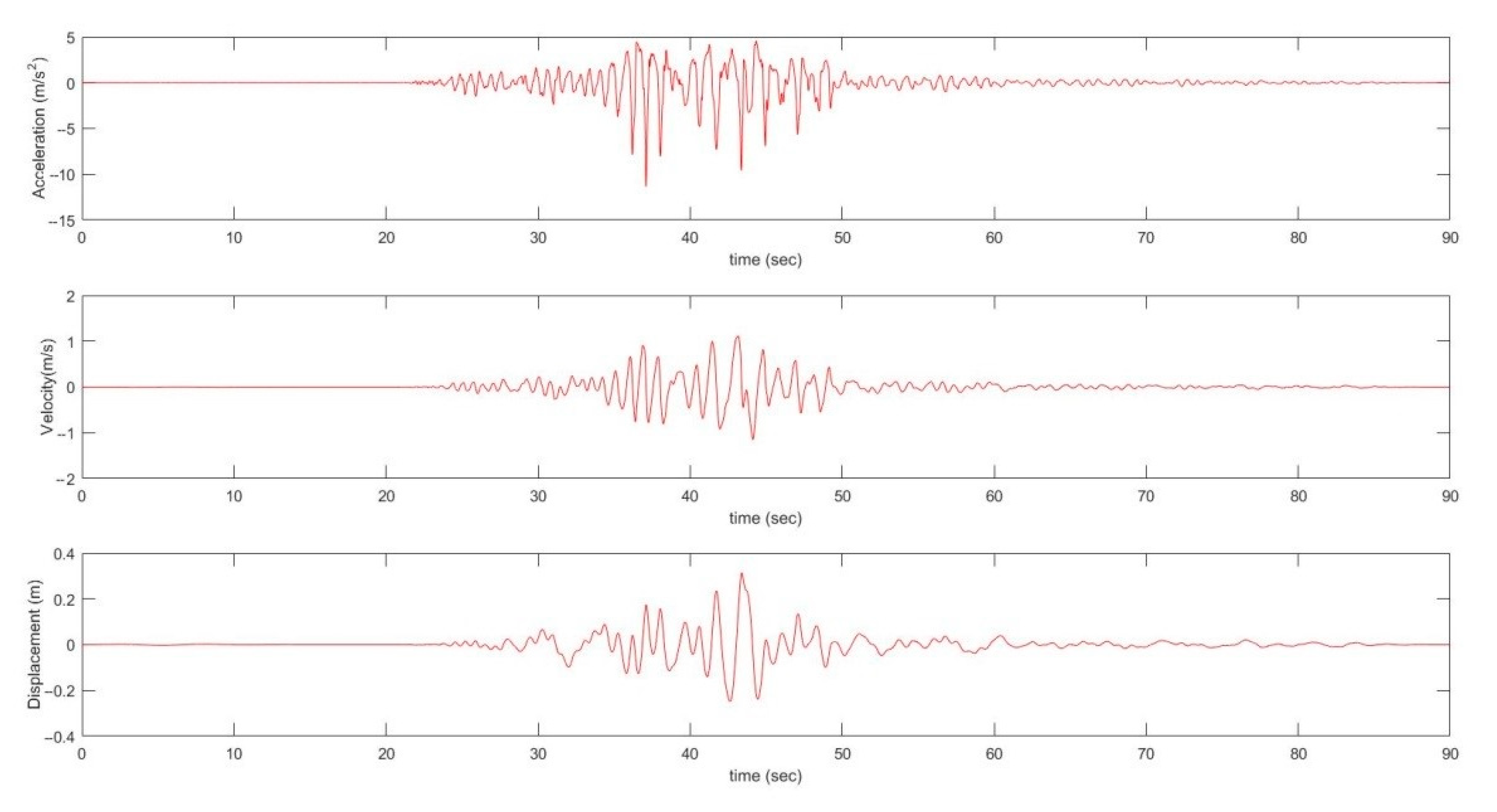
HS and FPA are used to determine the parameters of PID controllers for both cases. The maximum top displacement of uncontrolled structures under the seismic excitations defined in Table 1 and Table 2 are between 5.16 (Loma Prieta Saratoga—Aloha second component) and 97.53 cm (Chi-Chi, Taiwan, TCU084 first component). Therefore, the critical excitation is used as the first component of the TCU084 record of the Chi-Chi—Taiwan earthquake—in the optimization process to determine the parameters of PID and the objective function of both cases shown in Table 4. The input of this excitation to the structure is given in Figure 5. The objective functions such as the first-floor displacement (m), velocity (m/s), acceleration (m/s2) or total acceleration (m/s2) are very close for both metaheuristic algorithms. For example, the objective function; xr (the first-floor displacement) for case 1 is calculated as 0.1562 cm according to both algorithms if the displacement feedback strategy is considered. These values for case 2 are calculated according to FPA and HS as 0.1165 and 0.1161 cm, respectively. However, the harmony search algorithm has better results for the structural responses because the objective functions of HS which are determined by any numerical combination of design variables are revealed to be more successful little differences than those of FPA for different feedback strategies generally.
Table 4.
The optimum proportional–integral–derivative (PID) parameters according to flower pollination algorithm (FPA) and harmony search algorithm (HS).
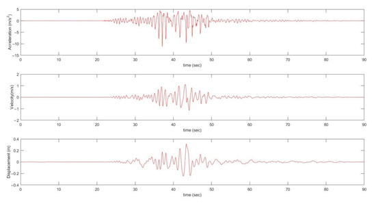
Figure 5.
The earthquake ground motions of Chi-Chi, Taiwan, TCU084 component.
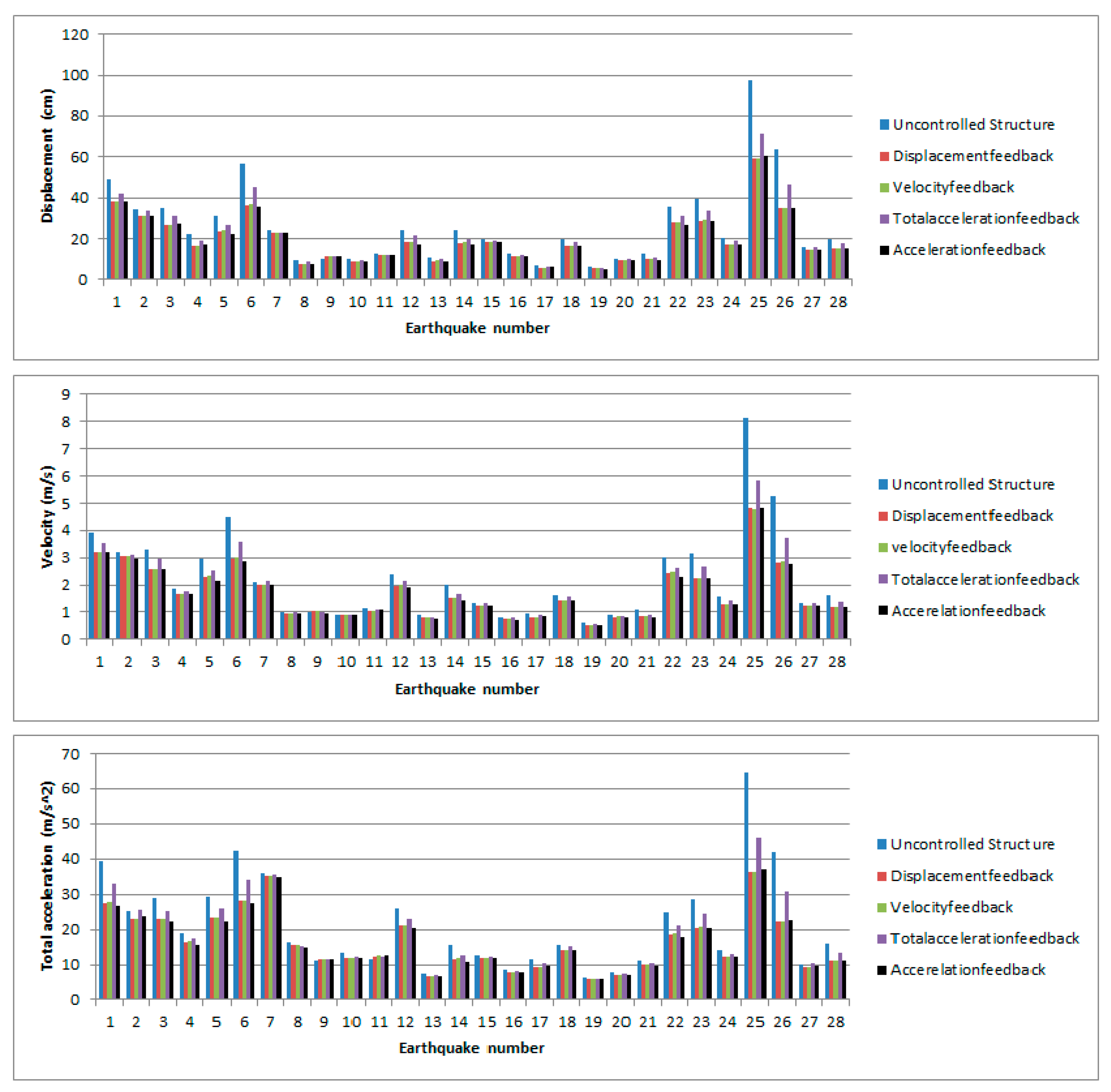
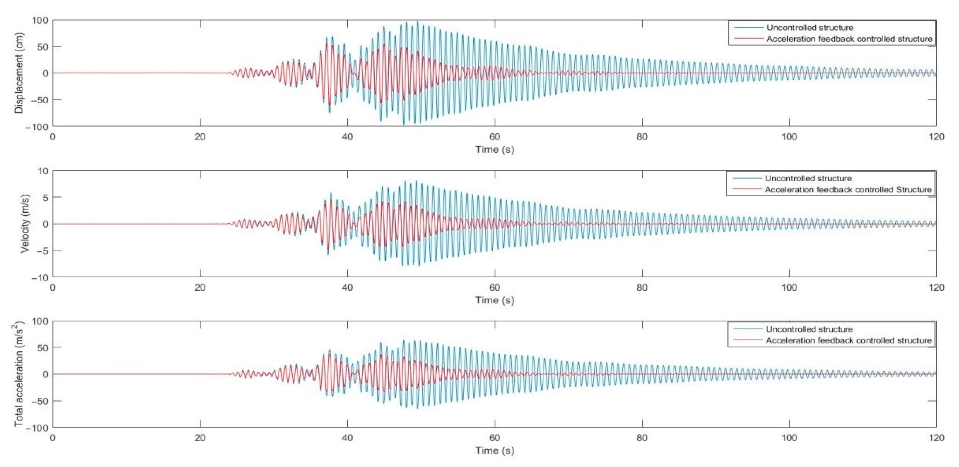
In both cases, the structural reactions under all ground motions (total 56 records) are reduced except one record (Gazli, USSR Karakyr first Component) using the active control system. In Case 1, the reductions in displacements vary between 0.63% (Imperial Valley-06 El Centro Array#6-s component) and 13.35% (Chi-Chi, Taiwan, TCU065 first component), while these values in Case 2 change between 2.50% (Imperial Valley-06 Bonds Corner first component) and 45.46% (Chi-Chi, Taiwan TCU084 s component). The reductions in structural responses in Case 2 are more noticeable than these values in Case 1. The main reason is the distribution of the control force which is limited to up to 10% of the total mass of the structure. In the first three ground motions with high structural reactions (earthquake number 25 in Table 1, and 19, and 26 in Table 2), the results of the different feedback strategies are close to each other. However, the acceleration feedback under 56 ground motions is the most suitable feedback for both cases. The maximum structural responses of all excitations and the time history responses of acceleration feedback control for the critical excitation for cases according to harmony search are shown in Figure A1, Figure A2, Figure A3 and Figure A4 in Appendix A. Maximum displacement, velocity and total acceleration values of uncontrolled structures values under near-fault ground motions with a pulse are 55.24 cm, 4.54 m/s, and 37.98 m/s2. By using active control with the acceleration feedback strategy, these values are reduced to 49.30 cm, 4.05 m/s, and 34.45 m/s2 for Case 1 and 42.39 cm, 3.33 m/s, and 27.99 m/s2 for Case 2, respectively. Under near-fault ground motions without a pulse, the displacement values of these uncontrolled and controlled cases (Case 1 and Case 2) are calculated as 97.53, 84.51 and 60.39 cm, respectively, while 8.15, 6.97 and 4.85 m/s are the velocity values and 64.72, 55.49 and 37.02 m/s2 are the acceleration values, respectively. In addition, top story values (xtop) are reported for the critical excitation in Table 4. As expected, Case 2 has significant superiority comparing to Case 1 since Case 2 contains active control in all stories.
4. Conclusions
In this study, active-controlled structures with different combinations and feedbacks of the active control were investigated under seismic excitations using HA and FPA to evaluate the performances of various feedback strategies. The conclusions about the performances of the feedback strategies in the active-controlled structure are as follows:
- (1)
- The structural responses such as maximum displacement (from 97.53 to 60.39 cm), maximum velocity (from 8.14 to 4.85 m/s), and maximum total acceleration (from 64.72 to 37.02 m/s2) on the first (ground) floor are reduced under seismic excitations using the active control system, respectively.
- (2)
- The properties of the structure and the ground motions play an important role in the performances of the feedback strategies. Acceleration feedback (more successful in reducing structural reactions of at least 30 out of 56 ground motions) is generally the most appropriate type of feedback for numerical examples and earthquake records.
- (3)
- HS and FPA are an important solution method to determine the optimum PID parameters for different feedback strategies.
- (4)
- The position of the control system on each floor is more advantageous to keep the control force limit (3050 for Case 1 and 338 KN for Case 2) at the appropriate value in terms of applicability.
As the main advantage of the method compared to other studies, the proposed method using PID controllers tuned via metaheuristic methods provides a realized control approach. The control system is optimized by directly considering the time-domain response of the structure and utilizing a powerful search of design variables taken as control parameters in metaheuristic-based optimization. This method also considers limitations related to the physical application of the method, such as the time delay and control force limitations.
Author Contributions
S.U., G.B., and S.M.N. generated the analysis code. S.U. and S.M.N. developed the theory background and formulations of the active control system. The modification of HS was done by S.U. and G.B. The text of the paper was written by S.M.N., G.B., and S.U. The figures were drawn by S.M.N., G.B., and S.U. S.K. and Z.W.G. edited the paper and supervised the research direction. All authors have read and approved the final manuscript.
Funding
This work was supported by the National Research Foundation of Korea (NRF) grant funded by the Korea government (MSIT) (2020R1A2C1A01011131). This research was also supported by the Energy Cloud R&D Program through the National Research Foundation of Korea (NRF) funded by the Ministry of Science, ICT (2019M3F2A1073164).
Institutional Review Board Statement
Not applicable.
Informed Consent Statement
Not applicable.
Data Availability Statement
The data can be provided via e-mail by authors.
Conflicts of Interest
The authors declare no conflict of interest.
Appendix A
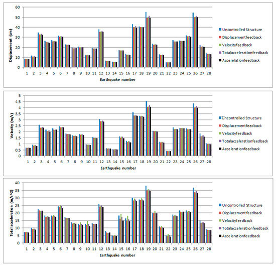
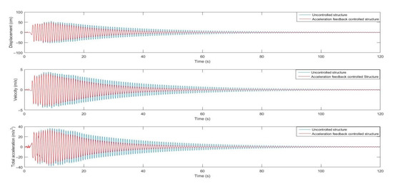
Figure A1.
The maximum structural responses of different feedback control under near-fault ground motions with a pulse and the time history of critical excitation for Case 1 according to the harmony search algorithm.
Figure A1.
The maximum structural responses of different feedback control under near-fault ground motions with a pulse and the time history of critical excitation for Case 1 according to the harmony search algorithm.
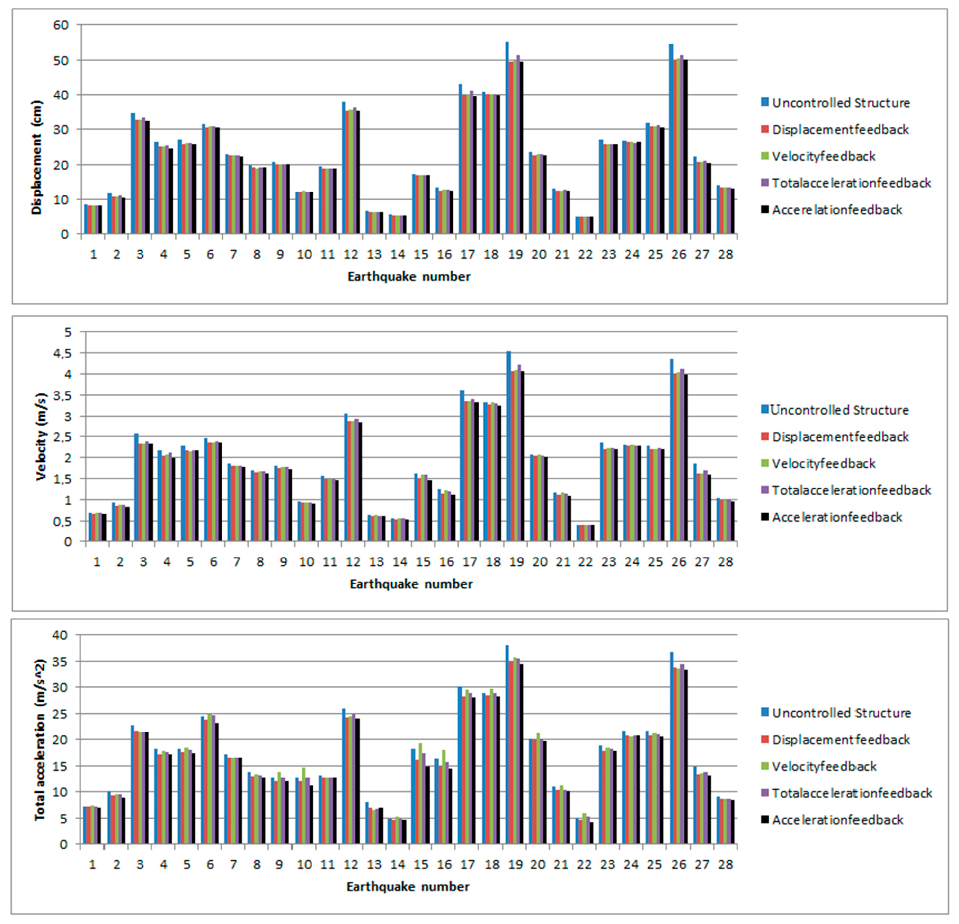
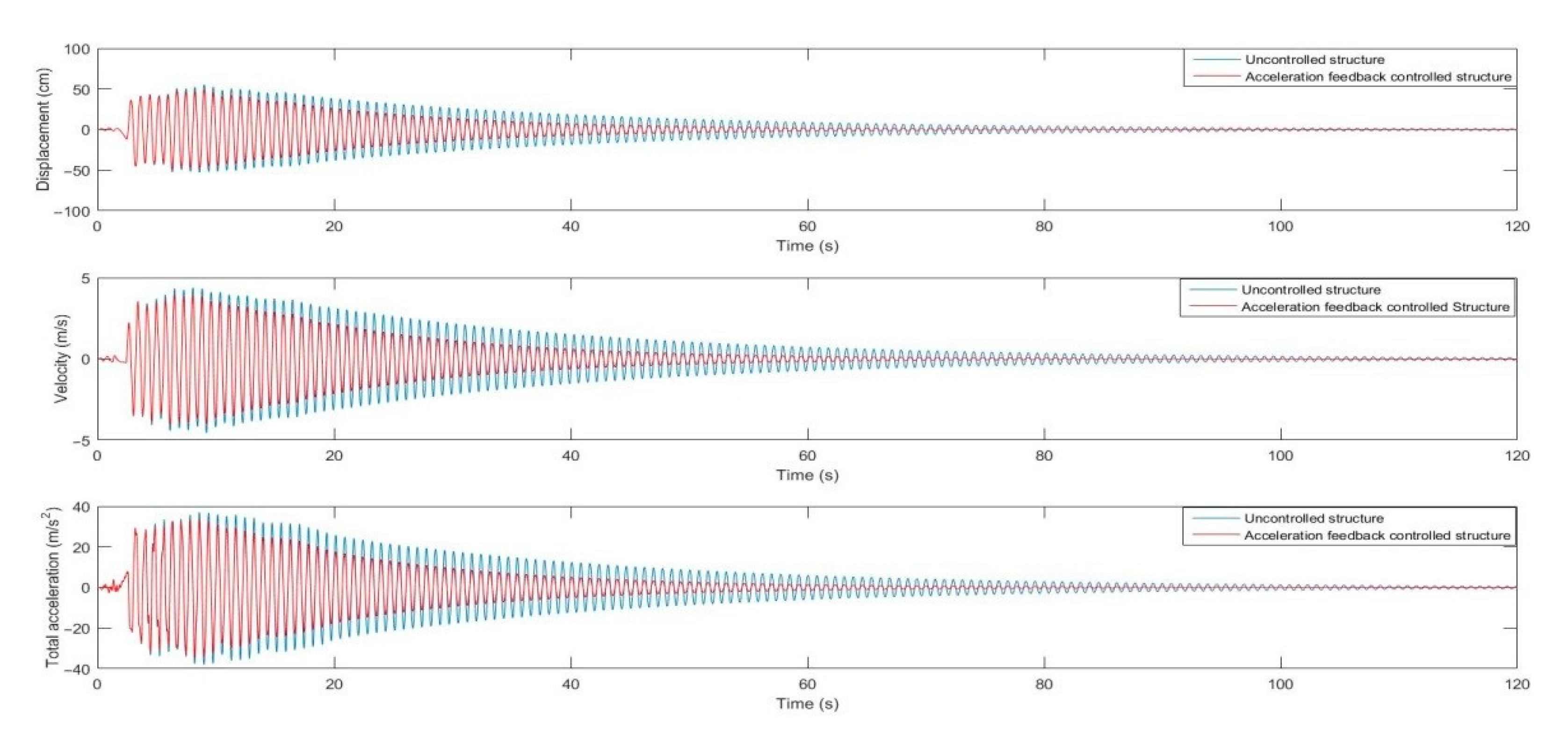
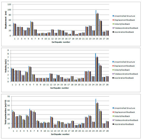

Figure A2.
The maximum structural responses of different feedback control under near-fault ground motions without a pulse and the time history of critical excitation for Case 1 according to the harmony search algorithm.
Figure A2.
The maximum structural responses of different feedback control under near-fault ground motions without a pulse and the time history of critical excitation for Case 1 according to the harmony search algorithm.
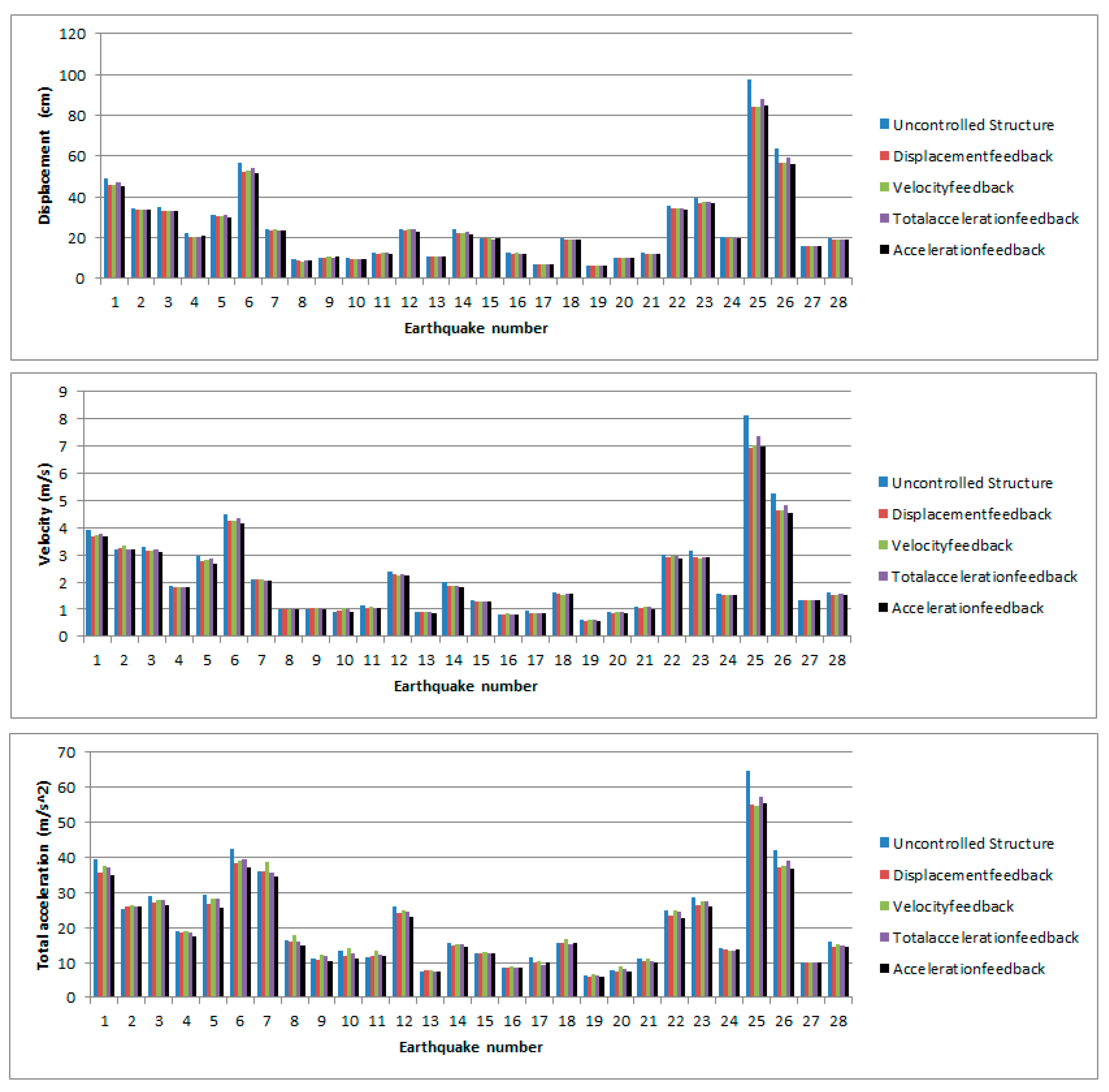
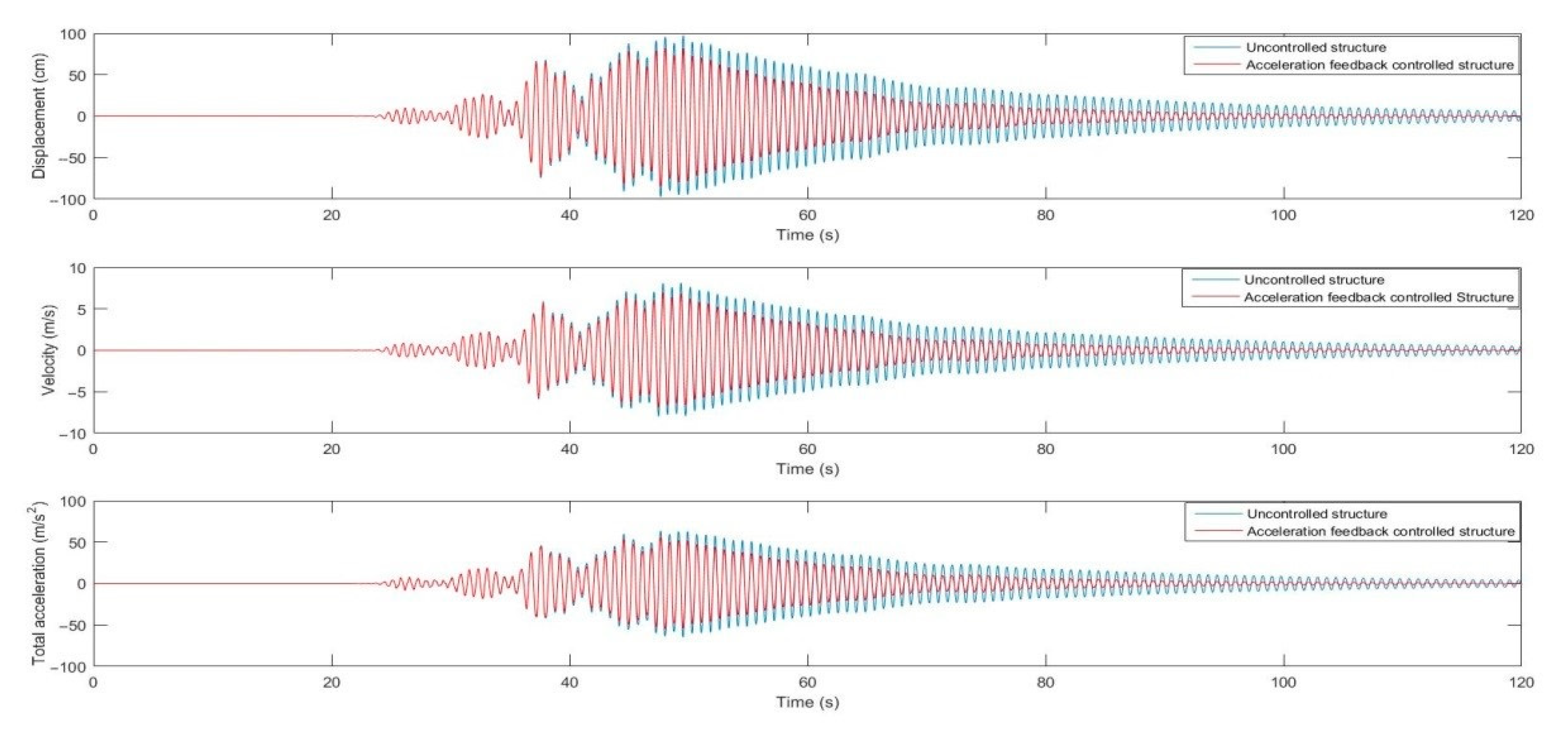
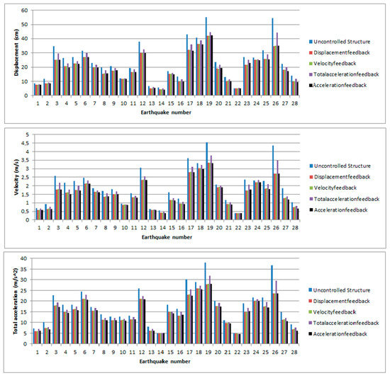
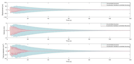
Figure A3.
The maximum structural responses of different feedback control under near-fault ground motions with a pulse and the time history of critical excitation for Case 2 according to the harmony search algorithm.
Figure A3.
The maximum structural responses of different feedback control under near-fault ground motions with a pulse and the time history of critical excitation for Case 2 according to the harmony search algorithm.
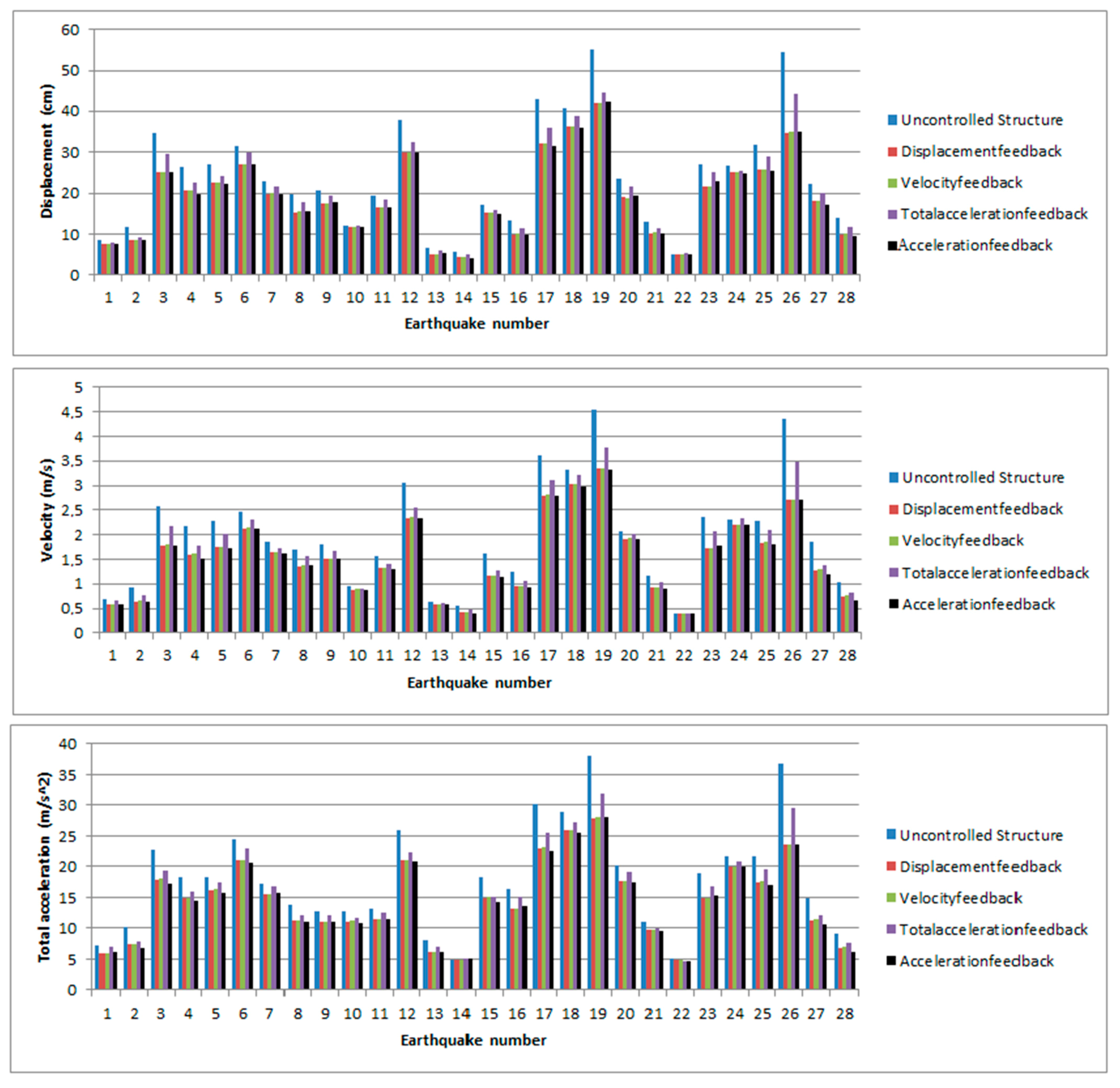

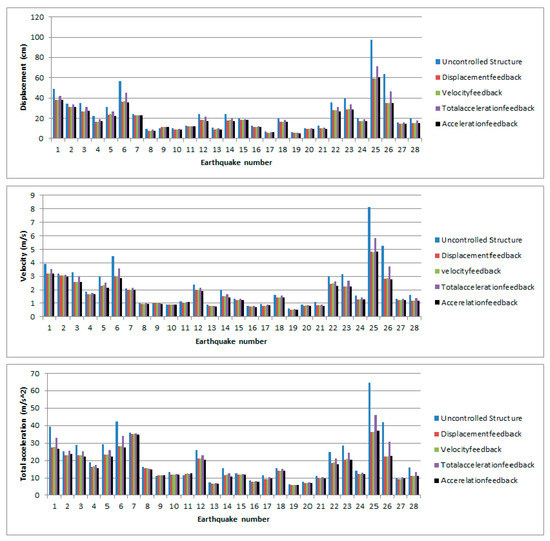

Figure A4.
The maximum structural responses of the different feedback control under near-fault ground motions without a pulse and the time history of critical excitation for Case 2 according to the harmony search algorithm.
Figure A4.
The maximum structural responses of the different feedback control under near-fault ground motions without a pulse and the time history of critical excitation for Case 2 according to the harmony search algorithm.
References
- Zuk, W. Kinetic structures. Civil Eng. 1968, 39, 62–64. [Google Scholar]
- Yang, J.N.; Samali, B. Control of tall buildings in along-wind motion. J. Struct. Eng. 1983, 109, 50–68. [Google Scholar] [CrossRef]
- Abdel-Rohman, M.; Leipholz, H.H. Active control of tall buildings. J. Struct. Eng. 1983, 109, 628–645. [Google Scholar] [CrossRef]
- Samali, B.; Yang, J.N.; Liu, S.C. Active control of seismic-excited buildings. J. Struct. Eng. 1985, 111, 2165–2180. [Google Scholar] [CrossRef]
- Chung, L.L.; Lin, R.C.; Soong, T.T.; Reinhorn, A.M. Experimental study of active control for MDOF seismic structures. J. Eng. Mech. 1989, 115, 1609–1627. [Google Scholar] [CrossRef]
- Chung, L.; Wu, L.; Jin, T. Acceleration feedback control of seismic structures. Eng. Struct. 1998, 20, 62–74. [Google Scholar] [CrossRef]
- Nigdeli, S.M. Effect of feedback on PID controlled active structures under earthquake excitations. Earthq. Struct. 2014, 6, 217–235. [Google Scholar] [CrossRef]
- Ulusoy, S.; Bekdas, G.; Nigdeli, S.M. Active structural control via metaheuristic algorithms considering soil-structure interaction. Struct. Eng. Mech. 2020, 75, 175–191. [Google Scholar]
- Ulusoy, S.; Nigdeli, S.M.; Bekdaş, G. Novel metaheuristic-based tuning of PID controllers for seismic structures and verification of robustness. J. Build. Eng. 2020, 33, 101647. [Google Scholar] [CrossRef]
- Arfiadi, Y.; Hadi, M.N.S. Passive and active control of three-dimensional buildings. Earthq. Eng. Struct. Dynam. 2000, 29, 377–396. [Google Scholar] [CrossRef]
- Bakioglu, M.; Aldemir, U. A new numerical algorithm for sub-optimal control of earthquake excited linear structures. Int. J. Numer. Methods Eng. 2001, 50, 2601–2616. [Google Scholar] [CrossRef]
- Alli, H.; Yakut, O. Fuzzy sliding-mode control of structures. Eng. Struct. 2005, 27, 277–284. [Google Scholar] [CrossRef]
- Nigdeli, S.M.; Boduroglu, B.H. Active tendon control of torsionally irregular structures under near-fault ground motion excitation. Comput. Aid. Civil Infrastruct. Eng. 2013, 28, 718–736. [Google Scholar] [CrossRef]
- Jiang, X.; Adeli, H. Neuro-genetic algorithm for non-linear active control of structures. Int. J. Numer. Methods Eng. 2008, 75, 770–786. [Google Scholar] [CrossRef]
- Yakut, O.; Alli, H. Neural based sliding-mode control with moving sliding surface for the seismic isolation of structures. J. Vib. Control. 2011, 17, 2103–2116. [Google Scholar] [CrossRef]
- Guclu, R. Sliding mode and PID control of a structural system against earthquake. Math. Comput. Model. 2006, 44, 210–217. [Google Scholar] [CrossRef]
- Ghaffarzadeh, H.; Younespour, A. Active tendons control of structures using block pulse functions. Struct. Control. Health Monit. 2014, 21, 1453–1464. [Google Scholar] [CrossRef]
- Kayabekir, A.E.; Bekdaş, G.; Nigdeli, S.M.; Geem, Z.W. Optimum design of PID controlled active tuned mass damper via modified harmony search. Appl. Sci. 2020, 10, 2976. [Google Scholar] [CrossRef]
- Geem, Z.W.; Kim, J.H.; Loganathan, G.V. A new heuristic optimization algorithm: Harmony search. Simulation 2001, 76, 60–68. [Google Scholar] [CrossRef]
- Yang, X.S. Flower pollination algorithm for global optimization. In Proceedings of the International Conference on Unconventional Computing and Natural Computation, Orleans, France, 3–7 September 2012; Springer: Berlin/Heidelberg, Germany, 2012; pp. 240–249. [Google Scholar]
- MathWorks Inc. MATLAB R2015b; MathWorks Inc.: Natick, MA, USA, 2015. [Google Scholar]
- Federal Emergency Management Agency. FEMA P-695. In Quantification of Building Seismic Performance Factors; Federal Emergency Management Agency: Washington, DC, USA, 2009. [Google Scholar]
- Chopra, A.K.; Chintanapakdee, C. Comparing response of SDF systems to near-fault and far-fault earthquake motions in the context of spectral regions. Earthq. Eng. Struct. Dyn. 2001, 30, 1769–1789. [Google Scholar] [CrossRef]
- Pacific Earthquake Engineering Research Center (PEER NGA DATABASE). Available online: http://peer.berkeley.edu/nga (accessed on 20 May 2020).
- Pnevmatikos, N.G.; Gantes, C.J. Control strategy for mitigating the response of structures subjected to earthquake Actions. Eng. Struct. 2010, 32, 3616–3628. [Google Scholar] [CrossRef]
Publisher’s Note: MDPI stays neutral with regard to jurisdictional claims in published maps and institutional affiliations. |
© 2021 by the authors. Licensee MDPI, Basel, Switzerland. This article is an open access article distributed under the terms and conditions of the Creative Commons Attribution (CC BY) license (http://creativecommons.org/licenses/by/4.0/).