Article

The Impact of Hydrogeological Features on the Performance of Underground Pumped-Storage Hydropower (UPSH)

1
Institute of Environmental Assessment and Water Research (IDAEA), Severo Ochoa Excellence Center of the Spanish Council for Scientific Research (CSIC), Jordi Girona 18-26, 08034 Barcelona, Spain
2
Avignon University, UMR EMMAH, University of Avignon, 84000 Avignon, France
3
Hydrogeology & Environmental Geology, Urban and Environmental Engineering research unit, University of Liège (Belgium), 4000 Liège, Belgium
4
Geology and Applied Geology, Polytech Mons, University of Mons, 7000 Mons, Belgium
*
Author to whom correspondence should be addressed.
Appl. Sci. 2021, 11(4), 1760; https://doi.org/10.3390/app11041760
Submission received: 21 January 2021 / Revised: 12 February 2021 / Accepted: 13 February 2021 / Published: 17 February 2021
(This article belongs to the Special Issue Advances in Underground Energy Storage for Renewable Energy Sources)

Abstract

:

Featured Application

This work evaluates the influence of groundwater exchanges occurring in the context of underground pumped storage hydropower using abandoned mines on the efficiency and on the environment. The findings are useful to define (1) design criteria of future underground pumped storage hydropower plants and (2) screening methodologies to choose the best places to construct them.

Abstract

Underground pumped storage hydropower (UPSH) is an attractive opportunity to manage the production of electricity from renewable energy sources in flat regions, which will contribute to the expansion of their use and, thus, to mitigating the emissions of greenhouse gasses (GHGs) in the atmosphere. A logical option to construct future UPSH plants consists of taking advantage of existing underground cavities excavated with mining purposes. However, mines are not waterproofed, and there will be an underground water exchange between the surrounding geological medium and the UPSH plants, which can impact their efficiency and the quality of nearby water bodies. Underground water exchanges depend on hydrogeological features, such as the hydrogeological properties and the groundwater characteristics and behavior. In this paper, we numerically investigated how the hydraulic conductivity (K) of the surrounding underground medium and the elevation of the piezometric head determined the underground water exchanges and their associated consequences. The results indicated that the efficiency and environmental impacts on surface water bodies became worse in transmissive geological media with a high elevation of the piezometric head. However, the expected environmental impacts on the underground medium increased as the piezometric head became deeper. This assessment complements previous ones developed in the same field and contributes to the definition of (1) screening strategies for selecting the best places to construct future UPSH plants and (2) design criteria to improve their efficiency and minimize their impacts.

1. Introduction

Renewable energies, such as solar or wind, may not be sufficiently efficient since they are intermittent and random, and consequently, their production of electricity is not adapted to the demand [1,2,3,4]. For this reason, they must be combined with energy storage systems (ESSs) [5] that allow for balancing the production and the demand [6]. ESSs are useful to store the surplus of electricity during periods of low demand and to generate electricity when the demand increases. Pumped storage hydropower (PSH) is the most worldwide used EES [7] because it allows for the storage and production of large amounts of electricity [8]. For example, about 95% of the utility-scale energy storage in the United States is PSH [9], and up to 99% in the European Union [10].
PSH plants consist of two reservoirs placed at different elevations (upper and lower reservoirs). The excess of electricity during low demand periods is stored in the form of potential energy by pumping water from the lower to the upper reservoir. Later, during high demand periods, electricity is produced by discharging the water through turbines from the upper to the lower reservoir [11]. Despite its extensive use, PSH has limitations [12,13,14], the most important being that a specific topography is required as both reservoirs must be located at different elevations [15]. Consequently, PSH plants can only be installed in relatively steep areas [16].
Underground pumped storage hydropower (UPSH) [17] is an opportunity to increase the capacity of managing the electrical production in areas where a conventional PSH is not possible. In addition, UPSH avoids some of the adverse environmental impacts related to PSH, and to hydropower in general, such as modifying the flow discharge in a river or changing the seasonal flow regime [18,19]. UPSH uses an underground cavity as the lower reservoir (underground reservoir) and constructs the upper reservoir at the surface [20] or, alternatively, at a shallow depth.
While the underground reservoir can be specifically excavated [21], the most inexpensive (i.e., efficient) option can be to take advantage of abandoned underground mines [22,23]. In addition, there are numerous mines that could be potentially used for UPSH. For example, in France, there are up to 4710 active mines and 101,616 abandoned mines [24], and, in Belgium, there are 964 active mines and more than 5000 abandoned mines [25]. Clearly, not all of these mines are suitable for constructing an UPSH plant; however, the objectives of electricity production and storage could be reached by using only a small portion of them.
For example, in France, these objectives could be reached by using 0.1% of the total available mines [26], and, in Belgium, it would be possible to obtain up to e 4896 MWh considering only mines with suitable characteristics for UPSH [27]. However, since mines are generally not waterproofed, it is expected that water exchanges will occur between the underground reservoir of UPSH plants and the surrounding groundwater systems [28]. This fact may entail negative consequences in terms of the environmental impacts [29,30,31] and for the efficiency (η) of UPSH [32]. We refer to η as the ratio between the energy used for pumping water from the underground reservoir and the energy generated when water is discharged from the upper reservoir under ideal conditions. Thus, energy losses due to conversion issues are not considered.
Recently, researchers observed that water exchanges may progressively fill the underground reservoir, reducing η. Occasionally, a volume of pumped water could actually not be fully discharged into the underground reservoir because the latter has been partially filled by underground water exchanges [33]. In addition, this volume of water must then be discharged into surface water systems, which could alter their quality because mine water is often not of an appropriate quality. If the released water is to impact the quality of the water bodies, it must be treated before its release to fulfill the current regulations concerning the water quality, such as the Water Framework Directive [34].
This decision should be taken based on the chemical composition of the water pumped from the mine and the expected reactions when mixing with surface water. If a treatment is needed, the additional investment required negatively affects the overall efficiency of the UPSH. Therefore, water exchanges with the surrounding geological medium are of paramount importance and must be investigated. Theoretically, these water exchanges depend on the local hydrogeological characteristics. Therefore, these features should play an essential role in the performance of UPSH influencing η and the potential environmental impacts. However, no studies were found that were focused on analyzing how hydrogeological properties influence water exchanges and their associated consequences. This information, however, appears to be crucial to define screening methodologies and to determine the best locations, in terms of η and the environmental impacts, where future UPSH plants could be constructed.
Thus, the objective of this paper was to determine the role of hydrogeological features (i.e., hydraulic conductivity and piezometric head) on the groundwater exchanges occurring in the context of UPSH and how they influence the efficiency of UPSH plants and their associated environmental impacts. This objective was reached by comparing the numerical results of different simulated scenarios based on an abandoned mine in Belgium that potentially could be used for constructing an UPSH plant.
The objective of this investigation was not to ascertain the system behavior at a specific site. The final goal was to provide a set of criteria to be considered during the design of future UPSH plants in these types of mining exploitation, to increase their efficiency and decrease the potential environmental impacts. Therefore, although the investigation was based on a real abandoned mine, the numerical models were purposely simplified to allow for determining the role of the different variables in the system behavior and extrapolating the main findings.
The main novelty of this work is that we investigated how the η of UPSH plants, and their associated environmental impacts vary depending on the hydraulic conductivity (K) of the surrounding medium and on the relative elevation of the piezometric head. This information, which has not yet been considered, will be crucial for designing future UPSH plants by taking advantage of abandoned mines.

2. Materials and Methods

2.1. Problem Statement

The groundwater model was based on the characteristics of an abandoned mine located in Martelange in south-east Belgium (Figure 1). This abandoned mine could be used for the construction of a UPSH plant.
The mine of Martelange was developed to extract metamorphic slates from lower Devonian formations in the Ardenne anticlinorium. Specifically, from the “Formation de La Roche”. The formation of these fractured slates started at the Lower Devonian, when the transgressive seas of the lower Devonian were at their maximum and clays and silts were deposited. Afterward, the clays and silt deposits were affected by different stages of deformation and metamorphism to become a dark fractured slate containing a thin bed of quartzites. The main slate cleavage (schistosity) was induced orthogonally to the main stress conditions during metamorphism phases but was not actually parallel to the bedding plane.
The exploitable layers had a dip between 55° and 66° [35]. Concerning the hydrogeological characteristics of the site, reference data was derived from previous works since, unfortunately, we did not have the opportunity to carry out hydraulic tests. According to previous works, these slates have a low global K (≈10−7 m/s [36]), and groundwater flows through preferential flow channels in multiple fractures. Thus, the hydrogeological behavior of the formation depends strongly on the aperture, density, and connectivity of the fractures.
The specific storage coefficient was 10−4 m−1, the saturated water content was 0.05, and the residual water content was 0.01. These parameters are typical of slate mines [22,37]. When the mining activities ceased, the piezometric head recovered, flooding the mine because its natural position is near the top of the mined cavities. The terms “hydraulic head” and “piezometric head” are used from this point forward to refer the water head inside the underground reservoir and the groundwater head, respectively.
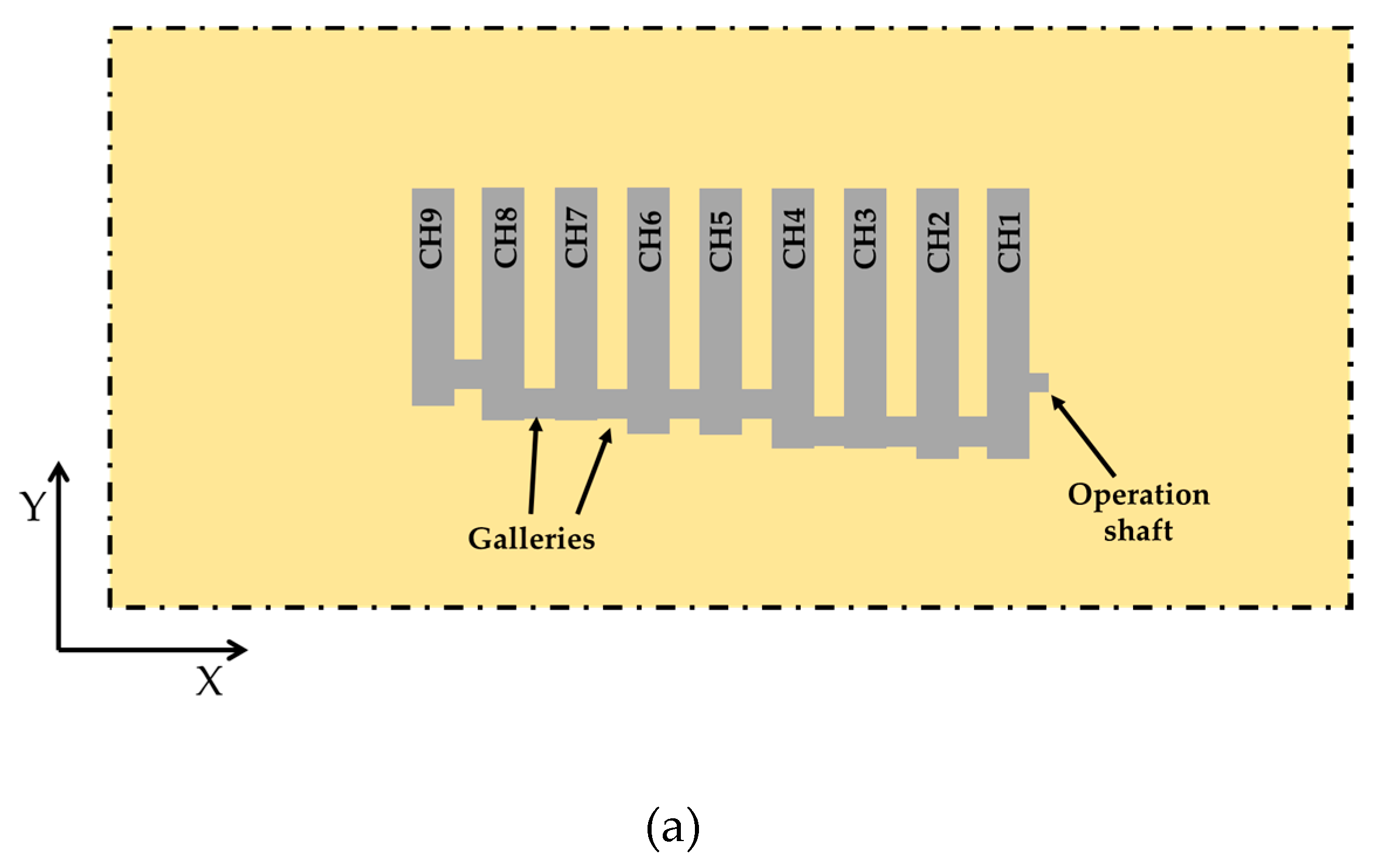
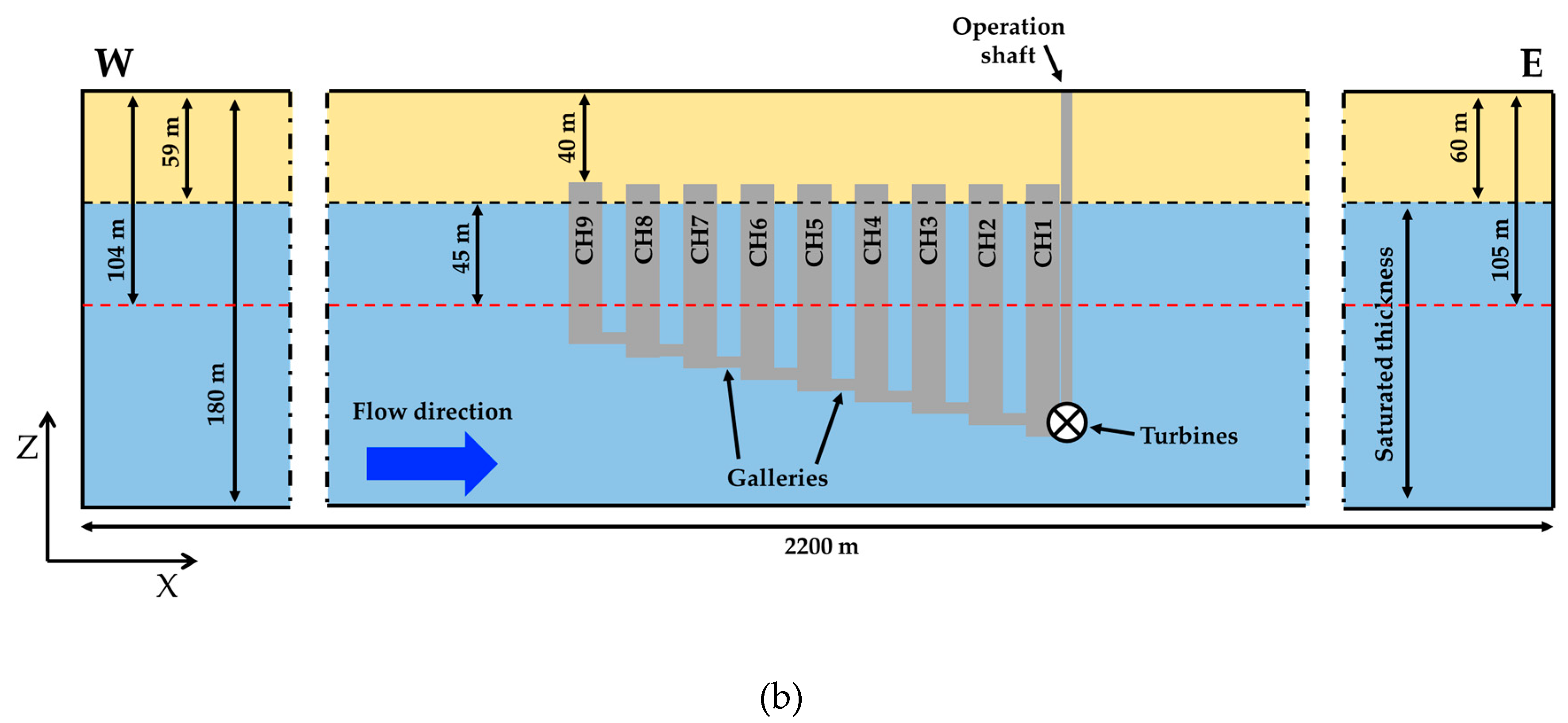
The underground cavity roughly consists of nine adjacent and vertical chambers (CH) that are connected through galleries. The volume of the chambers varies as they have different heights. Their width and length are, approximately, 15 and 45 m, respectively, while their heights vary from 70 to 110 m. The top of all chambers is located at the same depth (40 m below the surface), whilst their base depth decreases progressively from CH1 to CH9, with a decrement of about 5 m (Figure 2). Thus, the bases of chambers CH1, CH2, CH3, CH4, CH5, CH6, CH7, CH8, and CH9 are 150, 145, 140, 135, 130, 125, 120, 115, and 110 m deep, respectively.
A vertical 170-m-deep extraction shaft connects the base of CH1 with the surface [38]. Approximately, we calculated that a volume of 400,000 m3 could be potentially used for UPSH. This value was obtained by considering that (1) the top of the chambers is not exceeded by the hydraulic head, and (2) 10% of the maximum available volume is not used (i.e., pumped) to avoid total emptying of the reservoir (the underground reservoir is not totally emptied to avoid the pumps and turbines being out of the water). Consequently, this mine has a high water capacity.
If a surface reservoir was constructed strategically 500 m away in the northwest direction [38], it could be possible to reach a mean effective hydraulic head difference of 215 m between the underground and the upper reservoirs. Thus, a large amount of electricity could be stored and produced. Assuming an average pumping–discharge rate of 6 m3/s, the available power may reach up to 104 MW (this value may vary depending on the considered efficiency for the pumps and turbines). Figure 2 shows a simplified plain view (2a) and cross section (2b) of the modeled mine.

2.2. Description of the Numerical Model

2.2.1. Code

SUFT3D [39,40] is the finite element numerical code we used to develop the groundwater numerical model. This code solves the groundwater flow equation (Equation (1)) based on a mixed formulation of Richard’s equation proposed by Celia et al. [41] using the control volume finite element (CVFE):
θ t = _ · K _ _ ( θ ) _ h + _ · K _ _ ( θ ) _ z + q ,
where t is the time [T], θ is the water content [-], z is the elevation [L], h is the pressure head [L], q is a source/sink term [T−1], and K _ _ is the hydraulic conductivity tensor [LT−1] defined as
K _ _ = K r K _ _ S ,
where K _ _ S is the saturated permeability tensor [LT−1], and K r is the relative hydraulic conductivity [-] that varies from a value of 1 for full saturation to a value of 0 when the water phase is considered immobilized [42]. In the partially saturated zone, the value of K r evolves according with the following equations [43]:
θ = θ r ( θ s θ r ) ( h b h a ) ( h h a ) ,
K r ( θ ) = θ θ r θ s θ r
where θ r is the residual water content [-], θ s is the saturated water content [-], h a is the pressure head at which the water content is just lower than the saturated one [L], and h b is the pressure head at which the water content is the same as the residual one [L]. The K r varies linearly between the unsaturated and saturated zones as can be observed in Equations (3) and (4). This adopted linearity for defining the transition between saturated and unsaturated zones does not alter the results of the model, because this work is focused on processes that occurred only in the saturated portion of the soil, while this contributed to mitigate the convergence errors that are common when non-linear expressions are used.
The main reason we choose SUFT3D is because it has certain capabilities specifically designed for modelling underground mines, improving the realism and the results of the groundwater numerical model. Specifically, underground cavities were simulated as linear reservoirs using the hybrid finite element mixing cell (HFEMC) method [39,40] implemented in the SUFT3D code [44,45,46]. This method combines physically-based and spatially distributed models as well as black-box models. The domain can be divided into different subdomains depending on their characteristics with specific behaviors assigned depending on their nature.
Groundwater processes through unmined areas, which were modeled with finite elements, were computed according to the flow equation in variably saturated porous media (Equation (1). Single mixing cells were used to discretize the underground cavities (i.e., chambers) that are modelled as linear reservoirs, which is similar to the box model approaches that consider a mean hydraulic head for the whole cell. The groundwater exchange between the domains modelled as linear reservoirs and those modelled as porous medium varies linearly [47] and is governed by the following internal dynamic Fourier boundary condition (BC) [40]:
Q i = α A ( h a q h u r ) ,
where h a q is the piezometric head in the aquifer [L], h u r is the hydraulic head in the underground reservoir [L], Q i is the exchanged flow [L3T−1], A is the exchange area [L2], and α is the exchange coefficient [T−1]. It is important to highlight that the water velocity inside the mixing cell is not considered; however, the influence of this particularity on the results was minimized by using different linear reservoirs for modelling the different chambers.
SUFT3D was also used because it allows adopting virtual connections that are essential for the purpose of this investigation. Virtual connections, that are also named “by-pass”, allow the establishment of hydraulic connections between non-adjacent subdomains that are modeled as linear reservoirs. Virtual connections are defined by a first-order transfer equation (Equation (5) that can be switched off or on according to the hydraulic head difference between the two connected subdomains:
Q v r = α v r ( h S D j h S D i ) ,
where h S D j and h S D i are the hydraulic heads inside each of the connected linear reservoirs, Q v r is the flow between reservoirs, and α v r is the exchange coefficient of the virtual connection [L2T−1]. Virtual connections allow constraining the maximum and minimum hydraulic heads into the underground reservoir. They are crucial for the development of the model, as it is not possible to anticipate the water exchanges and, therefore, when the underground reservoir will be full or empty.
Consequently, it is not possible to predict if a pumping or discharge can be carried out. Two types of virtual connections are implemented. The first one extracts immediately and automatically the discharged water when the underground reservoir is full. The virtual connection is switched off for most of the time, and it is only switched-on when the underground reservoir is completely full. At this moment, a value of 10 6   m 2 / d is adopted for α v r to force the surplus of discharged water to be extracted. The second virtual connection is used to avoid the hydraulic head being lower than the bottom of each chamber. In this case, the connection is switched on most of the time ( α v r = 10 6   m 2 / d to allow the hydraulic connection between chambers). Only when the hydraulic head is at a lower elevation than the bottom of a chamber is the virtual connection deactivated, thus, disconnecting individually each chamber from the rest of the underground reservoir if the hydraulic head is too low.

2.2.2. Characteristics of the Model

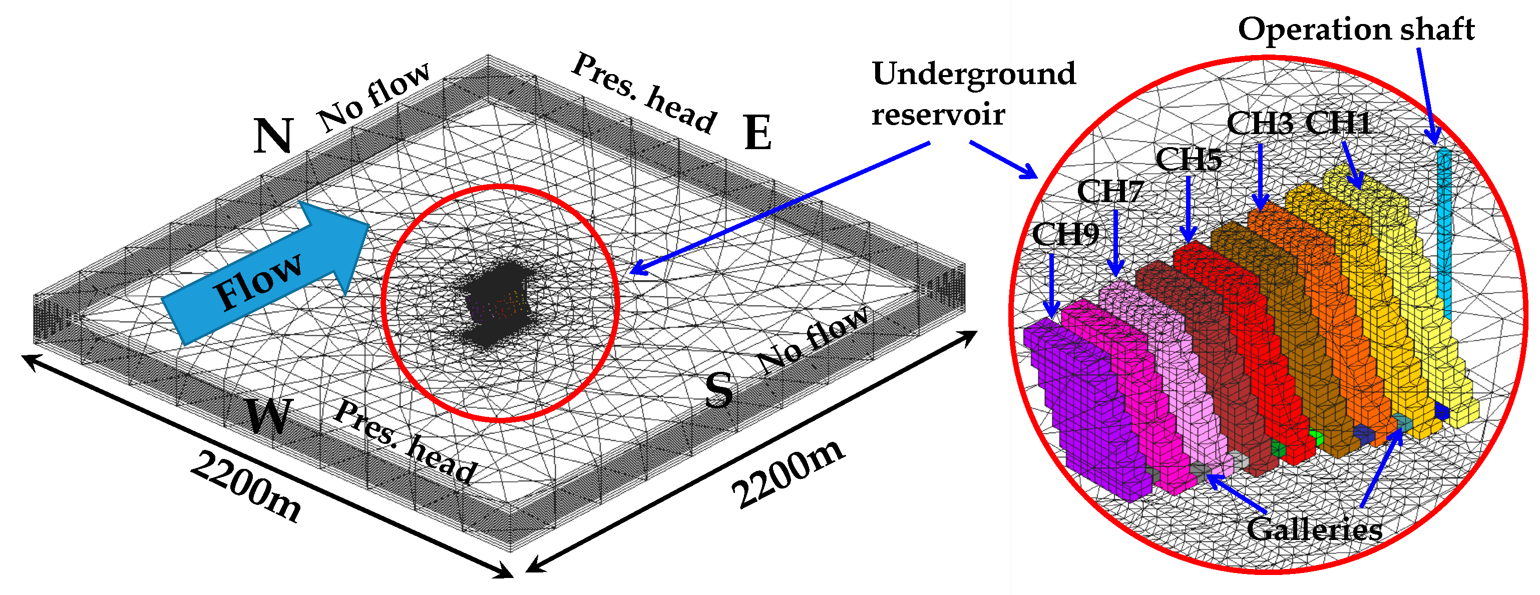
The numerical model is a squared domain with a thickness of 180 m and a side of 2200 m (Figure 2 and Figure 3). The simulated mine is placed just in the center of the model. Thus, the distance between the underground reservoir and the outer boundaries is of 1000 m. This distance allows to minimize the effects of the outer BCs on the results. The underground reservoir is represented by the nine underground chambers as described above (CH1 to CH9) that are hydraulically connected by galleries. The operation shaft is modeled using a rectangular prism adjacent to CH1 that connects the mine to the surface (Figure 2 and Figure 3).
The chambers and the operation shaft are modelled as independent domains that behave as linear reservoirs. Hydrogeologically, the groundwater flow behavior in the Martelange site is governed by fractures. However, it is known that a fracture-based groundwater flow is particularly difficult to implement in classical groundwater numerical models. In these types of cases, the underground medium is modeled using an equivalent porous medium (EPM) approach [42]. EPM approaches have been proven to be suitable to estimate the global groundwater behavior by numerous authors, including [48,49], particularly in sites with the presence of a high density of fractures as in the study site.
Concerning the hydraulic parameters, the K was modified in four different scenarios to observe its influence on the system behavior (note that the given EPM approach is considered, and K refers to the equivalent hydraulic conductivity). The values adopted for K in the different scenarios are specified in Section 2.2.3. The other hydraulic parameters were the same in all scenarios: the saturated and residual water contents were 0.05 and 0.01, respectively, while the specific storage coefficient was 10−4 m−1. The chosen parameters are typical of slate mines [22,37].
The spatial and temporal discretizations were as follows: The domain was divided vertically in 29 layers and horizontally discretized using 3D prismatic elements. The maximum horizontal size of the elements was 150 m at the outer boundaries, and the mesh was refined around the mine where the horizontal size was about 5 m (Figure 3). The model was composed of 64,844 nodes and 38,680 elements. The total simulation length was one year and was divided into constant time steps of 15 minutes. Larger time steps would induce convergence problems and errors.
Three different types of BCs were implemented. First, Dirichlet BCs were used to prescribe the piezometric head on the W and E outer boundaries of the model. Two different hypotheses (scenarios TOP and MIDDLE) were considered to assess the influence of the elevation of the piezometric head on the system performance. In the TOP scenarios, the piezometric head was fixed at an elevation (i.e., with respect to the bottom of the model) of 121 and 120 m on the upgradient (W) and downgradient (E) sides, respectively.
Consequently, the mine was totally full of water in the natural conditions. In the MIDDLE scenarios, groundwater head was prescribed at 76 and 75 m on the upgradient (W) and downgradient (E) sides, respectively. In this case, only half of the volume of the mine was full of water under natural conditions. As a result of the prescribed heads, the hydraulic gradient was 4.6 × 10⁻⁴ for both hypotheses, and the groundwater flowed from W to E (Figure 2). The BCs implemented at the outer boundaries did not change through the simulations. Secondly, no-flow BCs were assigned to the top and the bottom of the modeled domain and to the N and S boundaries.
Finally, pumping and discharge operations were simulated by use of a Neuman BC prescribing discharged or pumped water from the underground reservoir through the operation shaft. The value of the pumping and discharge rates were 5.94 m3/s, which is the required flow rate to fill or empty 10% of the underground reservoir in 2 hours. The frequency of pumping and discharge (operation scenario) was generated randomly since it is difficult to predict how the electrical generation and demand will evolve during a year. Every two hours, a choice was made between three options (discharge, pumping, or no-operation), and thus, the minimum duration of pumping or discharge operations was 2 hours. No limitation was adopted concerning the duration of pumping, discharge, or no-operation phases.
Figure 4 displays the operation scenarios randomly computed for the TOP and MIDDLE hypotheses during the 10 first days and assuming no-groundwater exchanges. Positive values indicate that water was discharged while negative values indicate that the water was pumped. The same pumping–discharge function was used for all scenarios within the same hypothesis concerning the position of the piezometric head (i.e., TOP or MIDDLE). Later, during the simulation process, the virtual connections (the internal boundary conditions explained in Section 2.2.1) constrained the pumping and discharge when the underground reservoir was filled or emptied faster than expected. This occurred because water exchanges cannot be anticipated and, thus, cannot be taken into account when defining the operation scenarios.
Figure 4 shows that the pumping–discharge frequencies were very similar for the TOP and MIDDLE scenarios. Differences were observed only during the first and third days. In the first day, we observed that the discharged water was higher for the MIDDLE scenario (red dotted line), and this occurred due to the BCs and the initial conditions. Initially, the underground reservoir was full in the scenario TOP, and, therefore, pumping was needed before any discharge.
There was a short pumping at the beginning, and then the underground reservoir was quickly filled by a short subsequent discharge; therefore, no more water could be introduced in the underground reservoir until the next pumping. However, in the scenario MIDDLE, the initial head was located at the half depth of the mine; therefore, more water could be discharged without the need for previous pumping. In contrast, during the third day, more water could be pumped in the scenario TOP than in the scenario MIDDLE. In this case, the natural piezometric head in the scenario MIDDLE was lower than in the TOP one; therefore, the underground reservoir was empty faster in the MIDDLE than in the TOP scenario, and the pumping was stopped earlier.
For the initial conditions, we assumed that the piezometric head distribution matched with that in natural conditions. Therefore, no previous pumping was considered before the start of the activity of the plant. Certain authors considered that, initially, the underground reservoir must be empty [50] because previous works needed to adapt the mine to be used as an underground reservoir, and this adaptation requires dewatering it. However, it was proven in a previous investigation that the differences between considering a previous pumping or not are negligible and only occur during the early periods [33].
This justifies the adopted hypothesis for constructing the numerical model used here. In addition, after any long shutdown of the plant activity, the piezometric head would reach its natural position. As a result, the initial conditions when the activity of the plant would be resumed are the same as those considered in the numerical model. It is important to clarify that the initial saturated thickness varies depending on the simulated scenario (TOP or MIDDLE), as they have different BCs on the outer boundaries.

2.2.3. Simulated Scenarios

In total, eight scenarios were modeled. They differed in the BCs implemented at the outer boundaries (scenarios TOP or MIDDLE) and the value of K of the surrounding medium (10−3, 10−4, 10−5, and 10−6 m/s). The objective of the scenarios was to assess the influence of the piezometric head elevation and K on the water exchanges and, therefore, on the η of the system and on the potential environmental impacts on surface water bodies. The TOP scenarios are denoted as TOP-3, TOP-4, TOP-5, and TOP-6 when the values of K are 10−3, 10−4, 10−5, and 10−6 m/s, respectively. Similarly, the MIDDLE scenarios are denoted as MID-3, MID-4, MID-5, and MID-6 when the values of K are 10−3, 10−4, 10−5, and 10−6 m/s, respectively.

2.2.4. Methodology Limitation

The main limitations of the methodology are that we considered (1) homogeneous and isotropic porous media and (2) pumping–discharge cycles defined randomly. However, these limitations do not interfere with the main objectives of this work that consist in providing general criteria regarding the impact of hydrogeological features on the efficiency and potential environmental impacts of UPSH. Clearly, during the design stage of future UPSH plants, we will need to develop more complex numerical models considering the heterogeneity of the porous medium and defining the pumping–discharge periods based on actual electricity price evolution.

3. Results and Discussion

3.1. Non-Dischargeable Volume of Water (Difference between Pumped and Discharge Water)

In this section, we analyze for all scenarios (1) the difference between pumped and discharged water and (2) the water exchanges between the underground reservoir and the surrounding medium. In principle, a surplus of pumped water that cannot be returned to the underground reservoir should be discharged into surface water systems, which may potentially alter the water quality or require additional water treatments.

3.1.1. TOP Scenarios (Influence of k)

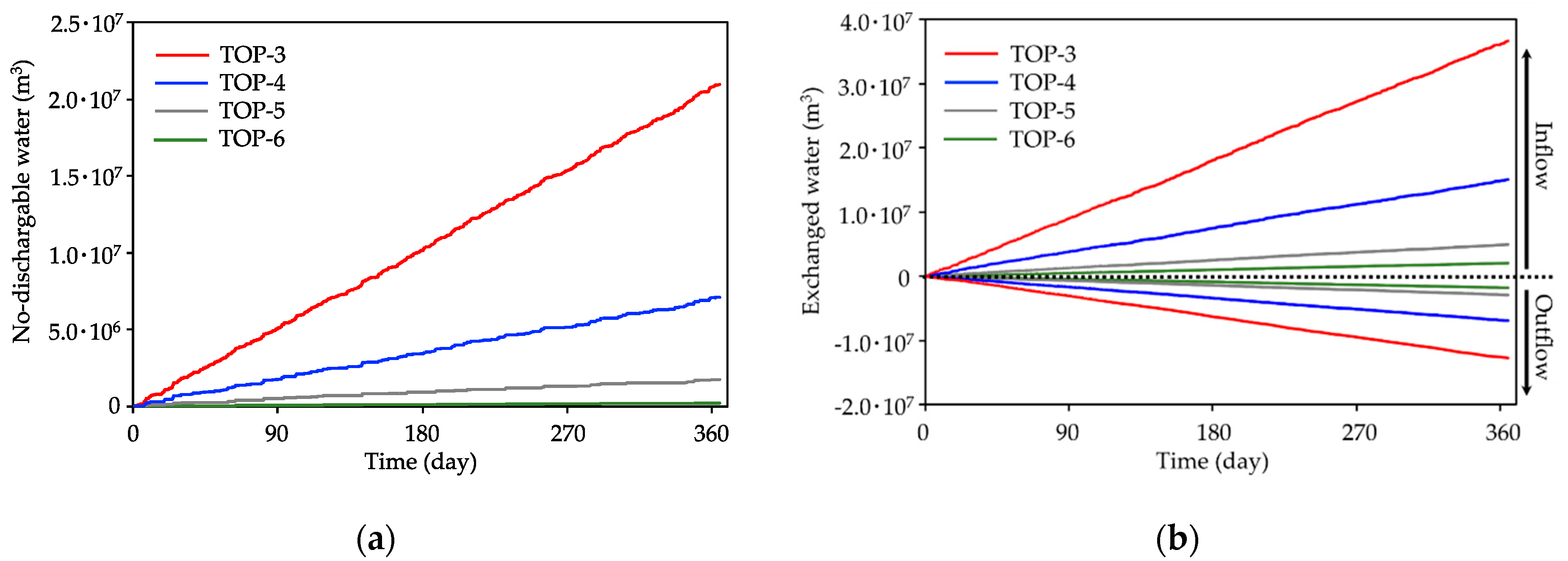
Figure 5 displays the evolution of the non-dischargeable volume of water (a) and the accumulated volume of the water exchanges in both directions (i.e., inflows and outflows) (b) for the TOP scenarios. In Figure 5b, positive values refer to water inflowing to the underground reservoir, while negative values refer to water outflowing from it. The results show that the K of the surrounding medium played a relevant role in the volume of water that could not be discharged into the underground reservoir. When the piezometric head was located at the top or near the top of the chambers, the hydraulic head inside the mine was usually below it during the operation of the plant.
Therefore, the total volume of water that inflows into the underground reservoir was larger than that flowing out (Figure 5b). Consequently, the underground reservoir was filled partially, and a portion of the pumped water could not be discharged. As expected, the water exchanges and, therefore, the volume of non-dischargeable water increased with K (Figure 5b). The accumulated volume of non-dischargeable water over a year varied between 2.1 × 10⁷ and 2.2 × 10⁵ m3 for the scenarios TOP-6 and TOP-3.
Considering that non-dischargeable water should be discharged into surface water systems, the environmental impacts would be considered as increasing as the surrounding medium becomes more permeable. Environmental impacts on the underground medium would be also higher for scenario TOP-3, since water exchanges between the mine and the surrounding groundwater system are also higher, i.e., changes in the hydraulic head elevation or in the water chemistry are easily transmitted to the groundwater in the surrounding medium.

3.1.2. MIDDLE Scenarios (Influence of k)

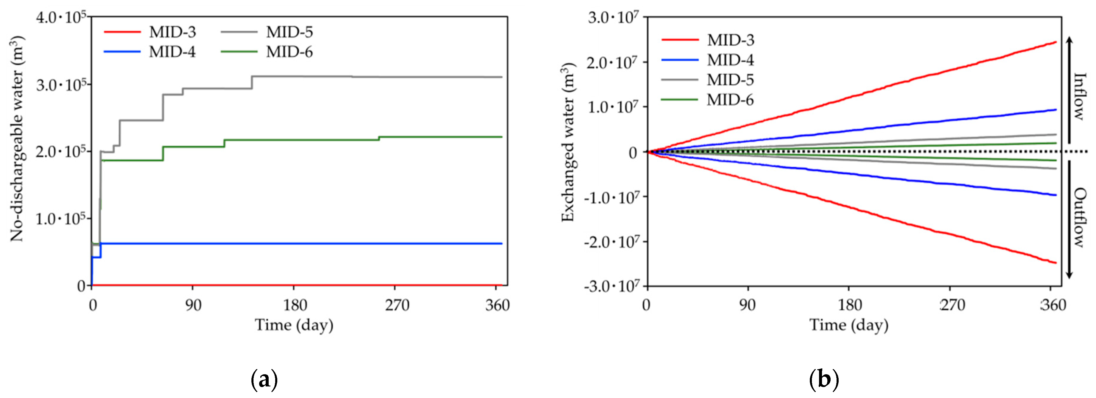
Figure 6 shows the evolution of the non-dischargeable volume of water (a) and the accumulated volume of water exchanges in both directions (i.e., the inflows and outflows) (b) for the MIDDLE scenarios. In this case, the influence of K was lower than in TOP scenarios and the non-dischargeable volume of water did not evolve proportionally with k. This behavior was related to the elevation of the hydraulic head with respect to the piezometric head in the surrounding medium. Given that the piezometric head was located at a half depth, the hydraulic head in the mine was sometimes higher and sometimes lower, depending on the operation schedule of the plant.
Therefore, in contrast to the TOP scenarios, similar volumes of water were exchanged in both directions (toward the underground medium and toward the underground reservoir) (Figure 6b). Thus, the inflows and outflows were more equilibrated than in the TOP scenarios, and less water was accumulated at the surface reservoir. In scenario MID-3, non-dischargeable water was not accumulated because the surrounding medium was so permeable that pumping and discharge did not modify the hydraulic head greatly because pumped water is quickly replaced by water from the surrounding medium or discharged water is transferred quickly to it. In addition, when the hydraulic head is modified by consecutive pumping or discharge periods, it returns quickly to the elevation of the piezometric head after the cessation of these periods.
As a result, the hydraulic head never reaches the top of the underground reservoir and water can be always discharged. This behavior is also reflected in Figure 6b where it is possible to observe the high volume of water exchanged in both directions. In scenario MID-4, the volume of non-dischargeable water increased slightly since the water exchanges were constrained by the K of the surrounding groundwater system, and the top of the chambers was reached occasionally as a consequence of consecutive discharge periods. This is the same reason for which a volume of non-dischargeable water is accumulated in scenario MID-5; however, in this case, the final volume was larger than in scenario MID-4 because the K was lower, and thus, the water exchanges were more constrained.
However, the trend changed for scenario MID-6 since the non-discharged volume of water decreased with respect to the scenario MID-5. Contrary to the observed trend in scenarios MID-3, MID-4, and MID-5, the non-discharged volume of water decreased when K was reduced more than 10-5 m/s (i.e., scenario MID-6). In scenario MID-6, the water exchanges were very low (Figure 6b) due to the value of k, and the system response was more similar to that of an isolated underground reservoir. Given that the operation scenarios were designed considering an isolated underground reservoir, the head evolved as expected and the top of the underground reservoir was not exceeded during most of the simulated time. If the K was reduced lower than 10-6 m/s, the non-discharged volume of water would decrease even more.
Concerning the environmental impacts into surface water bodies, the largest impacts were expected for scenario MID-5; however, they were much smaller than those in the TOP scenarios. Nevertheless, the largest environmental impacts in the underground medium were expected for scenario MID-3. Despite the fact that all the pumped water can be discharged into the underground reservoir, the results showed that water exchanges were higher than in the other scenarios, which indicates that the interaction between the UPSH plant and the surrounding materials, and therefore the impact on the groundwater, was high.

3.1.3. Influence of the Piezometric Head Elevation

The comparison between Figure 5 and Figure 6 shows that the volumes of non-dischargeable water were higher in the TOP scenarios. This means that expected environmental impacts on surface water bodies increased with the higher elevation of the piezometric head. Concerning the impacts on the surrounding groundwater head distribution, they would be similar with different elevations of the piezometric head. The magnitude of the produced oscillations should depend only on the value of K (magnitudes are proportional to k) but not on the initial depth of the piezometric head.
However, in the TOP scenarios, the piezometric head will oscillate systematically below the elevation of the natural piezometric head, whilst, in the MIDDLE scenarios, the piezometric head will oscillate around the natural position of the piezometric head. With regard to the impacts on the groundwater quality, they were expected to be larger when the piezometric head was lower since the magnitude of the outflow increased, which can be deduced by comparing Figure 5b and Figure 6b, and therefore, the spreading of mine water in the surrounding medium also increased. If the piezometric head is at the top, the hydraulic head is mostly located below it, and therefore, groundwater from the aquifer tends to flow toward the mine minimizing the spreading of mine water in the surrounding medium.

3.2. Variations in η

In this section, we analyze the influence of the water exchanges on the global η of UPSH plants. Considering that the pumped volume of water was the same in all scenarios, the variation of η over a year was computed by comparing the total discharged water obtained from the simulations by the total discharged water under ideal conditions (i.e., without the existence of groundwater exchanges). Table 1 shows the variation in the η for all the simulated scenarios with respect to the ideal reference scenario. Overall, the η was less affected by groundwater exchanges in the MIDDLE compared with in the TOP scenarios. In the TOP scenarios, the η was clearly related to the value of k, decreasing up to 37.3% in scenario TOP-3 with respect to the ideal reference scenario.
The results show that the variation in the η was acceptable for values of K smaller than 10−5 m/s; however, if K was increased above this value, the η decreased dramatically. The differences in η were much smaller in the MIDDLE scenarios, and all of them were acceptable. The η decreases in some scenarios were a consequence of exceptional large periods of discharge during which the underground reservoir was totally filled. In terms of η , a low piezometric head in the surrounding medium would be more favorable. However, additional problems could arise if the piezometric head was too low, as sometimes there would not be enough water to pump in the underground reservoir, and a portion of the excess of electricity could not be stored, decreasing the η of the plant.

3.3. Previous Works and Future Investigations

Previous studies have investigated the role of the hydrogeological parameters on the potential impacts induced by UPSH in the underground medium [16,30]. The present investigation goes further and shows how the K controls the potential environmental impacts on surface water bodies and on the global η of the plant. While the results are useful to understand the system behavior and to define screening methodologies, further investigation should be done regarding not only the influence of other hydrogeological parameters, such as the effective porosity, but also considering heterogeneities in the underground medium. In addition, the importance of the shape and volume of the available underground cavity should be assessed.
The results showed that, under certain circumstances, the discharge of large volumes of the pumped groundwater into surface water bodies would be needed. In addition, the effects on the piezometric head of pumping and discharge may alter the interactions between the groundwater and nearby surface water bodies. Consequently, it would be advisable to investigate how UPSH may influence the e-flows of nearby rivers [51] by considering UPSH plants during the environmental flow assessment processes.
This paper also investigated, for the first time, the relevance of the elevation of the piezometric head in terms of η and the environmental impacts. The results showed that the relative elevation of the piezometric head was crucial for the operation of a UPSH plant, and for this reason, it should certainly deserve more investigation in the future.
Finally, we assessed the influence of the water exchanges on the global η of UPSH plants. To date, only one study had investigated the relation between groundwater exchanges and η [32]. However, this previous investigation only considered the influence of groundwater exchanges on the η of pumps and turbines. While the findings of this previous study were relevant, the reported variations of η were much lower than those obtained in this paper.
The current investigation went further and considered the variations in the global η of UPSH by comparing the energy consumed for pumping water from the underground reservoir and that obtained by discharging water from the upper reservoir. Considering that the η of the pumps and turbines depends on the head difference between reservoirs, it is advisable to investigate the effect on their η of different positions for the piezometric head as in the present paper.

4. Conclusions

This is the first paper to assess the role of hydrogeological features (i.e., the K and piezometric head) on the groundwater exchanges that occur in the context of UPSH using abandoned mines and, therefore, on the η of UPSH plants and their associated environmental impacts. Despite the relevant η issues, those related to potential environmental impacts are paramount importance, as UPSH plants must fulfill the current regulations concerning water bodies. For example, in the European context, the Water Framework Directive [34] states that countries must preserve the “good state” of water bodies.
Considering that, under some scenarios, the water quality may be deteriorated under the influence of UPSH (e.g., if abandoned coal mines are used as underground reservoirs [29]) additional water treatments may be required before releasing the water surplus into surface water bodies. Overall, the final goal of this work was to improve the knowledge about the interactions between an UPSH and the groundwater to complement previous studies developed in this field and, in this way, to contribute to establish criteria for (1) the selection of abandoned mines that are most suitable for UPSH and (2) designing future UPSH plants. The main conclusions of this paper are the following.
  • The K of the surrounding medium drove the groundwater exchanges. Consequently, K played an important role concerning the η of UPSH and its associated environmental impacts. Thus, K should be considered in the selection process of abandoned mines when constructing future UPSH plants.
  • The influence exerted by K depended on the elevation of the piezometric head with respect to the mine. If the piezometric head was located at a high elevation, high values of K were harmful for the η and the environmental impacts. When the natural piezometric head was located at the half elevation of the mine, the K did not affect the η of UPSH nor the environmental impacts over surface water bodies; however, the impact could become important in terms of the groundwater quality, increasing with high values of K.
  • The elevation of the piezometric head was relevant and must be considered when designing an UPSH plant. The results showed that, for the same values of K, the η was higher, and the environmental impacts over surface water bodies were lower if the piezometric head was located at a low elevation. However, the potential impacts on the groundwater increased, since the outflows from the underground reservoir to the surrounding geological medium increased with low piezometric heads. Consequently, an agreement between the η , the environmental impacts into surface water bodies, and those generated in nearby aquifer systems will be needed in order to choose potential sites to implement UPSH.
The pumping–discharge frequencies must be adapted according to the K and the position of the piezometric head in order to increase the efficiency of UPSH plants. If the hydrogeological parameters are not considered, large volumes of water could be not discharged into the underground reservoir under certain circumstances (i.e., large values K and high piezo metric heads). This would decrease the η and increase the environmental impacts on surface water bodies.
The model used in this investigation was purposely simplified to obtain general results applicable to other sites with similar features, which was the primary objective of this work. However, the consideration of a specific mine for constructing a UPSH plant requires site specific, detailed, and realistic numerical models. These models must consider all the characteristics of the site, such as the heterogeneity, the seasonal variations or the presence of fractures and faults. In addition, these models should be in 3D and should simulate the system behavior over a large period of years.

Author Contributions

Conceptualization, E.P.; methodology, E.P.; software, P.O.; investigation, E.P., A.P., P.O., P.G. and A.D.; resources, P.O., A.D.; data curation, E.P.; writing—original draft preparation, E.P., A.P., P.O., P.G. and A.D.; writing—review and editing, E.P., A.P., P.O., P.G. and A.D.; visualization, E.P.; supervision, A.D.; project administration, A.D, E.P.; funding acquisition, E.P. and A.D. All authors have read and agreed to the published version of the manuscript.

Funding

IDAEA-CSIC is a Centre of Excellence Severo Ochoa (Spanish Ministry of Science and Innovation, Project CEX2018-000794-S). This research was funded by the Public Service of Wallonia–Department of Energy and Sustainable Building through the Smartwater project. E.P. was also funded by the Barcelona City Council through the Award for Scientific Research into Urban Challenges in the City of Barcelona 2020 (20S08708).

Institutional Review Board Statement

Not applicable.

Informed Consent Statement

Not applicable.

Data Availability Statement

All analyzed data in this study has been included in the manuscript.

Conflicts of Interest

The authors declare no conflict of interest. The funders had no role in the design of the study; in the collection, analyses, or interpretation of data; in the writing of the manuscript; or in the decision to publish the results.

References

  1. Hu, Y.; Bie, Z.; Ding, T.; Lin, Y. An NSGA-II Based Multi-Objective Optimization for Combined Gas and Electricity Network Expansion Planning. Appl. Energy 2016, 167, 280–293. [Google Scholar] [CrossRef] [Green Version]
  2. Mileva, A.; Johnston, J.; Nelson, J.H.; Kammen, D.M. Power System Balancing for Deep Decarbonization of the Electricity Sector. Appl. Energy 2016, 162, 1001–1009. [Google Scholar] [CrossRef] [Green Version]
  3. Okazaki, T.; Shirai, Y.; Nakamura, T. Concept Study of Wind Power Utilizing Direct Thermal Energy Conversion and Thermal Energy Storage. Renew. Energy 2015, 83, 332–338. [Google Scholar] [CrossRef] [Green Version]
  4. Menéndez, J.; Fernández-Oro, J.M.; Loredo, J. Economic Feasibility of Underground Pumped Storage Hydropower Plants Providing Ancillary Services. Appl. Sci. 2020, 10, 3947. [Google Scholar] [CrossRef]
  5. Gebretsadik, Y.; Fant, C.; Strzepek, K.; Arndt, C. Optimized Reservoir Operation Model of Regional Wind and Hydro Power Integration Case Study: Zambezi Basin and South Africa. Appl. Energy 2016, 161, 574–582. [Google Scholar] [CrossRef] [Green Version]
  6. Delfanti, M.; Falabretti, D.; Merlo, M. Energy Storage for PV Power Plant Dispatching. Renew. Energy 2015, 80, 61–72. [Google Scholar] [CrossRef]
  7. Zhang, N.; Lu, X.; McElroy, M.B.; Nielsen, C.P.; Chen, X.; Deng, Y.; Kang, C. Reducing Curtailment of Wind Electricity in China by Employing Electric Boilers for Heat and Pumped Hydro for Energy Storage. Appl. Energy 2016, 184, 987–994. [Google Scholar] [CrossRef] [Green Version]
  8. Steffen, B. Prospects for Pumped-Hydro Storage in Germany. Energy Policy 2012, 45, 420–429. [Google Scholar] [CrossRef] [Green Version]
  9. Pumped-Storage Hydropower. Available online: https://www.energy.gov/eere/water/pumped-storage-hydropower (accessed on 8 October 2020).
  10. Menéndez, J.; Fernández-Oro, J.M.; Galdo, M.; Loredo, J. Efficiency Analysis of Underground Pumped Storage Hydropower Plants. J. Energy Storage 2020, 28, 101234. [Google Scholar] [CrossRef]
  11. Hadjipaschalis, I.; Poullikkas, A.; Efthimiou, V. Overview of Current and Future Energy Storage Technologies for Electric Power Applications. Renew. Sustain. Energy Rev. 2009, 13, 1513–1522. [Google Scholar] [CrossRef]
  12. Wong, I.H. An Underground Pumped Storage Scheme in the Bukit Timah Granite of Singapore. Tunn. Undergr. Space Technol. 1996, 11, 485–489. [Google Scholar] [CrossRef]
  13. Menéndez, J.; Fernández-Oro, J.M.; Galdo, M.; Loredo, J. Transient Simulation of Underground Pumped Storage Hydropower Plants Operating in Pumping Mode. Energies 2020, 13, 1781. [Google Scholar] [CrossRef] [Green Version]
  14. Menéndez, J.; Schmidt, F.; Konietzky, H.; Fernández-Oro, J.M.; Galdo, M.; Loredo, J.; Díaz-Aguado, M.B. Stability Analysis of the Underground Infrastructure for Pumped Storage Hydropower Plants in Closed Coal Mines. Energies 2019, 94, 103117. [Google Scholar] [CrossRef]
  15. Mueller, S.C.; Sandner, P.G.; Welpe, I.M. Monitoring Innovation in Electrochemical Energy Storage Technologies: A Patent-Based Approach. Appl. Energy 2015, 137, 537–544. [Google Scholar] [CrossRef] [Green Version]
  16. Pujades, E.; Willems, T.; Bodeux, S.; Orban, P.; Dassargues, A. Underground Pumped Storage Hydroelectricity Using Abandoned Works (Deep Mines or Open Pits) and the Impact on Groundwater Flow. Hydrogeol. J. 2016, 24, 1531–1546. [Google Scholar] [CrossRef] [Green Version]
  17. Uddin, N.; Asce, M. Preliminary Design of an Underground Reservoir for Pumped Storage. Geotech. Geol. Eng. 2003, 21, 331–355. [Google Scholar] [CrossRef]
  18. Kuriqi, A.; Pinheiro, A.N.; Sordo-Ward, A.; Garrote, L. Water-Energy-Ecosystem Nexus: Balancing Competing Interests at a Run-of-River Hydropower Plant Coupling a Hydrologic–Ecohydraulic Approach. Energy Convers. Manage. 2020, 223, 113267. [Google Scholar] [CrossRef]
  19. Suwal, N.; Huang, X.; Kuriqi, A.; Chen, Y.; Pandey, K.P.; Bhattarai, K.P. Optimisation of Cascade Reservoir Operation Considering Environmental Flows for Different Environmental Management Classes. Renew. Energy 2020, 158, 453–464. [Google Scholar] [CrossRef]
  20. Menéndez, J.; Schmidt, F.; Konietzky, H.; Bernardo Sánchez, A.; Loredo, J. Empirical Analysis and Geomechanical Modelling of an Underground Water Reservoir for Hydroelectric Power Plants. Appl. Sci. 2020, 10, 5853. [Google Scholar] [CrossRef]
  21. Madlener, R.; Specht, J.M. An Exploratory Economic Analysis of Underground Pumped-Storage Hydro Power Plants in Abandoned Coal Mines. SSRN J. 2013. [Google Scholar] [CrossRef] [Green Version]
  22. Bodeux, S.; Pujades, E.; Orban, P.; Brouyère, S.; Dassargues, A. Interactions between Groundwater and the Cavity of an Old Slate Mine Used as Lower Reservoir of an UPSH (Underground Pumped Storage Hydroelectricity): A Modelling Approach. Eng. Geol. 2017, 217, 71–80. [Google Scholar] [CrossRef] [Green Version]
  23. Menéndez, J.; Ordóñez, A.; Álvarez, R.; Loredo, J. Energy from Closed Mines: Underground Energy Storage and Geothermal Applications. Renew. Sustain. Energy Rev. 2019, 108, 498–512. [Google Scholar] [CrossRef]
  24. Références et projets|BRGM. Available online: https://www.brgm.fr/fr/resultats-donnees/references-projets (accessed on 18 January 2021).
  25. Poty, E.; Chevalier, E. Wallonie L’activité Extractive En Wallonie: Situation Actuelle et Perspectives; Laboratoire d’analyses litho et zoostratigraphiques: Liège, Belgium, 2004. [Google Scholar]
  26. Gombert, P.; Poulain, A.; Goderniaux, P.; Orban, P.; Pujades, E.; Dassargues, A. Potentiel de valorisation de sites miniers et carriers en step en France et en Belgique. LHB 2020, 4, 33–42. [Google Scholar] [CrossRef]
  27. Poulain, A. Etude de l’impact Sollicitations Cycliques Au Sein d’aquifères Non Confinés, à Différentes Échelles. Applications à Des Systèmes de Pompage–Turbinage En Carrières, Université de Mons. 2018. Available online: https://web.umons.ac.be/fpms/fr/evenements/etude-de-limpact-de-sollicitations-cycliques-au-sein-daquiferes-non-confines-a-differentes-echelles-applications-a-des-systemes-de-pompage-turbinage-en-carrieres-par/ (accessed on 18 January 2021).
  28. Poulain, A.; Goderniaux, P.; de dreuzy, J.-R. Study of Groundwater-Quarry Interactions in the Context of Energy Storage Systems. 2016, 18, EPSC2016-9055. Available online: https://orbi.uliege.be/handle/2268/217789 (accessed on 18 January 2021).
  29. Pujades, E.; Jurado, A.; Orban, P.; Ayora, C.; Poulain, A.; Goderniaux, P.; Brouyère, S.; Dassargues, A. Hydrochemical Changes Induced by Underground Pumped Storage Hydropower and Their Associated Impacts. J. Hydrol. 2018, 563, 927–941. [Google Scholar] [CrossRef] [Green Version]
  30. Pujades, E.; Jurado, A.; Orban, P.; Dassargues, A. Parametric Assessment of Hydrochemical Changes Associated to Underground Pumped Hydropower Storage. Sci. Total Environ. 2019, 659, 599–611. [Google Scholar] [CrossRef] [Green Version]
  31. Pujades, E.; Orban, P.; Jurado, A.; Ayora, C.; Brouyère, S.; Dassargues, A. Water Chemical Evolution in Underground Pumped Storage Hydropower Plants and Induced Consequences. Energy Procedia 2017, 125, 504–510. [Google Scholar] [CrossRef]
  32. Pujades, E.; Orban, P.; Bodeux, S.; Archambeau, P.; Erpicum, S.; Dassargues, A. Underground Pumped Storage Hydropower Plants Using Open Pit Mines: How Do Groundwater Exchanges Influence the Efficiency? Appl. Energy 2017, 190, 135–146. [Google Scholar] [CrossRef]
  33. Pujades, E.; Orban, P.; Archambeau, P.; Kitsikoudis, V.; Erpicum, S.; Dassargues, A. Underground Pumped-Storage Hydropower (UPSH) at the Martelange Mine (Belgium): Interactions with Groundwater Flow. Energies 2020, 13, 2353. [Google Scholar] [CrossRef]
  34. Water Framework Directive. Available online: https://eur-lex.europa.eu/eli/dir/2000/60/oj (accessed on 4 February 2021).
  35. Anciaux, V. The Ardennes–Slate Throughout. de Leekëppert, Bulletin de Liaison 2019, 5. Available online: http://www.ardoise.lu/wp/wp-content/uploads/2019/11/2019-ARDENNES_1_AnciauxThilmany-VERSION-ANGLAISE-FINAL.pdf (accessed on 18 January 2021).
  36. Bouezmarni, M.; Denne, P.; Debbaut, V. Carte hydrogéologique de Wallonie 1/25000. 65/3-4, Bastogne–Wardin et 65/7-8 Fauvillers–Romeldange. 2006. Available online: http://hdl.handle.net/2268/98657 (accessed on 18 January 2021).
  37. Bear, J.; Cheng, A.H.-D. Modeling Groundwater Flow and Contaminant Transport; Theory and Applications of Transport in Porous Media; Springer: Dordrecht, Netherlands, 2010. [Google Scholar]
  38. Erpicum, S.; Archambeau, P.; Dewals, B.; Pirotton, M.; Pujades, E.; Orban, P.; Dassargues, A.; Cerfontaine, B.; Charlier, R.; Poulain, A.; et al. Underground Pumped Hydro-Energy Storage in Wallonia (Belgium) Using Old Mines–Potential and Challenges. 2017, 2984–2991. Available online: http://hdl.handle.net/2268/214205 (accessed on 18 January 2021).
  39. Brouyère, S.; Orban, P.; Wildemeersch, S.; Couturier, J.; Gardin, N.; Dassargues, A. The Hybrid Finite Element Mixing Cell Method: A New Flexible Method for Modelling Mine Ground Water Problems. Mine Water Environ. 2009, 28, 102–114. [Google Scholar] [CrossRef] [Green Version]
  40. Wildemeersch, S.; Brouyère, S.; Orban, P.; Couturier, J.; Dingelstadt, C.; Veschkens, M.; Dassargues, A. Application of the Hybrid Finite Element Mixing Cell Method to an Abandoned Coalfield in Belgium. J. Hydrol. 2010, 392, 188–200. [Google Scholar] [CrossRef] [Green Version]
  41. Celia, M.A.; Bouloutas, E.T.; Zarba, R.L. A General Mass-Conservative Numerical Solution for the Unsaturated Flow Equation. Water Resour. Res. 1990, 26, 1483–1496. [Google Scholar] [CrossRef]
  42. Dassargues, A. Hydrogeology: Groundwater Science and Engineering; CRC Press: Raton, FL, USA, 2018; ISBN 0-429-89440-6. [Google Scholar]
  43. Yeh, G.T.; Cheng, J.R.; Cheng, H.P. 3DFEMFAT: A 3-Dimensional Finite Element Model of Density-Dependent Flow and Transport through Saturated-Unsaturated Media; Department of Civil and Environmental Engineering, Pennsylvania State University: University Park, PA, USA, 1994. [Google Scholar]
  44. Brouyère, S. Etude et Modélisation du Transport et du Piégeage des Solutés en Milieu Souterrain Variablement Saturé. Evaluation des Paramètres Hydrodispersifs par la Réalisation et L’interprétation D’essais de Traçage in Situ. Doctoral Thesis, Université de Liège, Sart Tilman, Belgique, 18 December 2001. [Google Scholar]
  45. Brouyère, S.; Carabin, G.; Dassargues, A. Climate Change Impacts on Groundwater Resources: Modelled Deficits in a Chalky Aquifer, Geer Basin, Belgium. Hydrogeol. J. 2004, 12, 123–134. [Google Scholar] [CrossRef] [Green Version]
  46. Carabin, G.; Dassargues, A. Modeling Groundwater with Ocean and River Interaction. Water Resour. Res. 1999, 35, 2347–2358. [Google Scholar] [CrossRef]
  47. Orban, P.; Brouyère, S. Groundwater Flow and Transport Delivered for Groundwater Quality Trend Forecasting by TREND T2. 2006. Available online: http://hdl.handle.net/2268/78481 (accessed on 18 January 2021).
  48. Scanlon, B.R.; Mace, R.E.; Barrett, M.E.; Smith, B. Can We Simulate Regional Groundwater Flow in a Karst System Using Equivalent Porous Media Models? Case Study, Barton Springs Edwards Aquifer, USA. J. Hydrol. 2003, 276, 137–158. [Google Scholar] [CrossRef]
  49. Hassan, S.M.T.; Lubczynski, M.W.; Niswonger, R.G.; Su, Z. Surface–Groundwater Interactions in Hard Rocks in Sardon Catchment of Western Spain: An Integrated Modeling Approach. J. Hydrol. 2014, 517, 390–410. [Google Scholar] [CrossRef]
  50. Kitsikoudis, V.; Archambeau, P.; Dewals, B.; Pujades, E.; Orban, P.; Dassargues, A.; Pirotton, M.; Erpicum, S. Underground Pumped-Storage Hydropower (UPSH) at the Martelange Mine (Belgium): Underground Reservoir Hydraulics. Energies 2020, 13, 3512. [Google Scholar] [CrossRef]
  51. Suwal, N.; Kuriqi, A.; Huang, X.; Delgado, J.; Młyński, D.; Walega, A. Environmental Flows Assessment in Nepal: The Case of Kaligandaki River. Sustainability 2020, 12, 8766. [Google Scholar] [CrossRef]
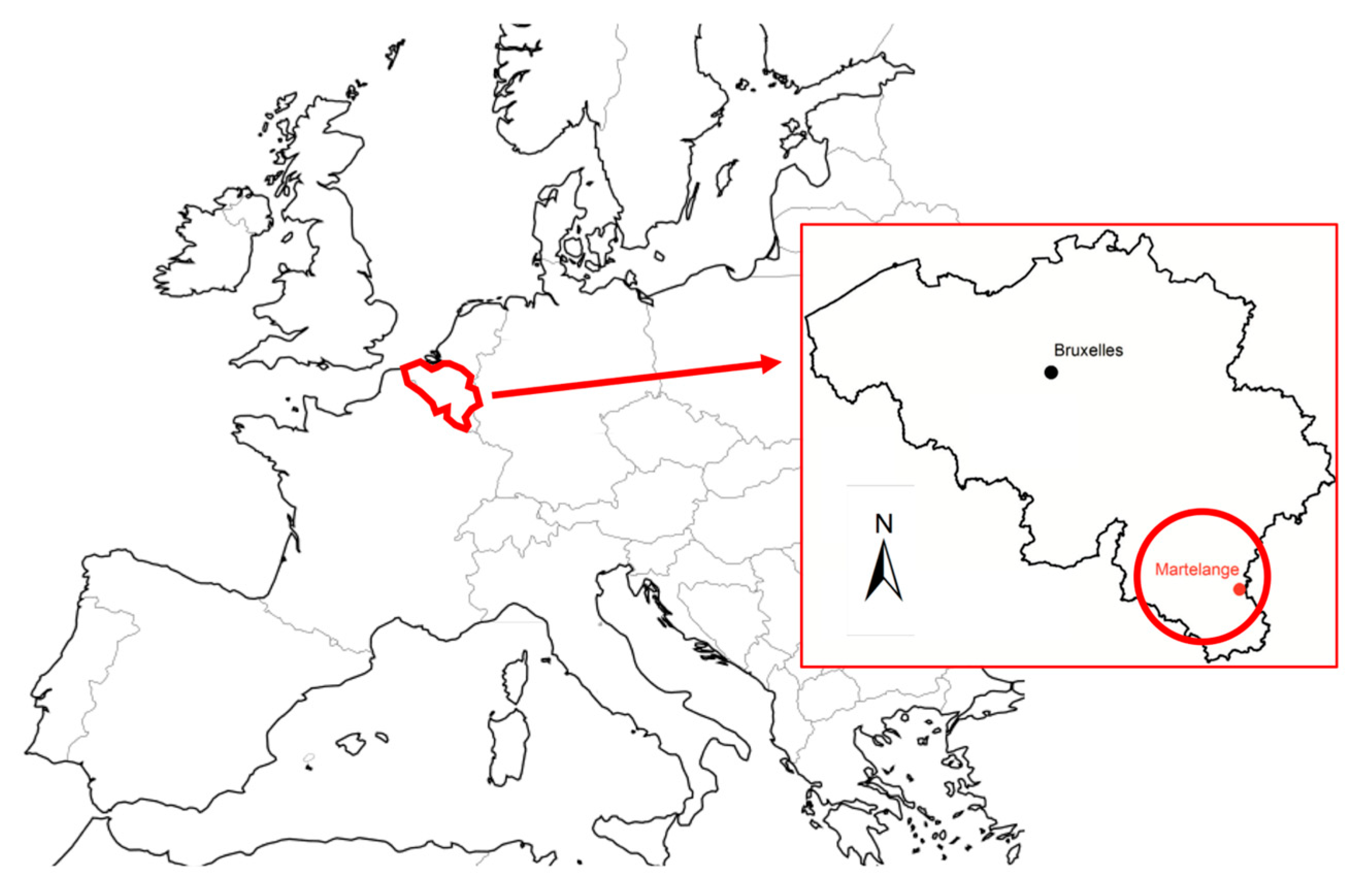
Figure 1. General view of Europe with Belgium highlighted with a red line (on the left) and a detailed view of Belgium (on the right) indicating the location of the considered mine (Martelange).
Applsci 11 01760 g001
Figure 2. Schematic plan view (a) and cross section (b) of the mine in Martelange that is considered in this study. The black and red dashed lines in (b) indicate the natural position of the piezometric head considered in the two simulated scenarios. The black line indicates the scenarios called TOP, whilst the red line indicates the scenarios denoted as MIDDLE. The pictures taken inside the chambers can be checked at http://tchorski.morkitu.org/2/martelange-02.htm.
Applsci 11 01760 g002aApplsci 11 01760 g002b
Figure 3. A detailed view of the modelled mine is shown on the right while a general view of the numerical model is shown on the left side of the figure. It is possible to observe how the bottom of the chambers increases progressively from west to east.
Applsci 11 01760 g003
Figure 4. Operation scenarios during the first 10 days for the TOP (blue continuous line) and MIDDLE (red dotted line) scenarios.
Applsci 11 01760 g004
Figure 5. Volume of water that cannot be discharged into the underground reservoir (a) and accumulated difference of water exchanges between the mine and the surrounding groundwater system (b) for the TOP scenarios.
Applsci 11 01760 g005
Figure 6. Volume of water that cannot be discharged into the underground reservoir (a) and the accumulated difference of water exchanges between the mine and the surrounding groundwater system (b) for the MIDDLE scenarios.
Applsci 11 01760 g006
Table 1. Variations in the efficiency ( Δ η ) with respect to an ideal reference scenario.
TOP Scenario Δ η   ( % ) MIDDLE Scenario Δ η   ( % )
TOP-3−37.3MID-30
TOP-4−12.6MID-4−0.1
TOP-5−3.1MID-5−0.6
TOP-6−0.4MID-6−0.4
Publisher’s Note: MDPI stays neutral with regard to jurisdictional claims in published maps and institutional affiliations.