Article

The Diagonal Arch Bridge, a Particular Case of Spatial Arch Bridges

by
Jesús Aguilar-Jiménez
,
Juan Manuel García-Guerrero
* and
Juan José Jorquera-Lucerga
Mining and Civil Engineering Department, Universidad Politécnica de Cartagena (UPCT), Paseo Alfonso XIII, 50, 30203 Cartagena, Spain
*
Author to whom correspondence should be addressed.
Appl. Sci. 2021, 11(4), 1869; https://doi.org/10.3390/app11041869
Submission received: 17 December 2020 / Revised: 23 January 2021 / Accepted: 13 February 2021 / Published: 20 February 2021
(This article belongs to the Section Civil Engineering)

Abstract

:

Featured Application

The findings of this paper could be useful both for researchers and practicing structural engineers, widening the scope of the available typologies in arch bridges.

Abstract

A diagonal arch bridge (DAB) is a particular case of arch bridge where the arch is rotated about a vertical axis passing through its crown so that each springing lies on a different side of the deck. A perpendicular arch bridge (PAB) is a particular case of DAB where the arch is rotated so that the arch plan is perpendicular to the deck axis. This paper includes a table of built bridges since 1989 and outlines the historical evolution of this type of bridge. Two main trends can be distinguished—one approach is focused on structural efficiency and the other is based on making aesthetics prevail, which often leads to structurally inefficient solutions. The main geometrical parameters are identified and the effect of the angle of rotation about a vertical axis is studied. Design constraints, such as the clearance requirements, are highlighted. In addition, the main structural systems, such as out-of-plane behavior, are identified and qualitatively studied, as an orientation for designers and a first step in future studies.

1. Introduction

At the end of this paper, the Supplementary Materials appendix includes a table of built diagonal arch bridges (DABs) (Table S1). Each bridge mentioned for the first time in this paper is referred to according to the format (xxletter) where xx is the last two digits of the year of construction and the letter (a or b…) identifies the bridge. Thus, for example, (97c) refers to bridge c, built in 1997.

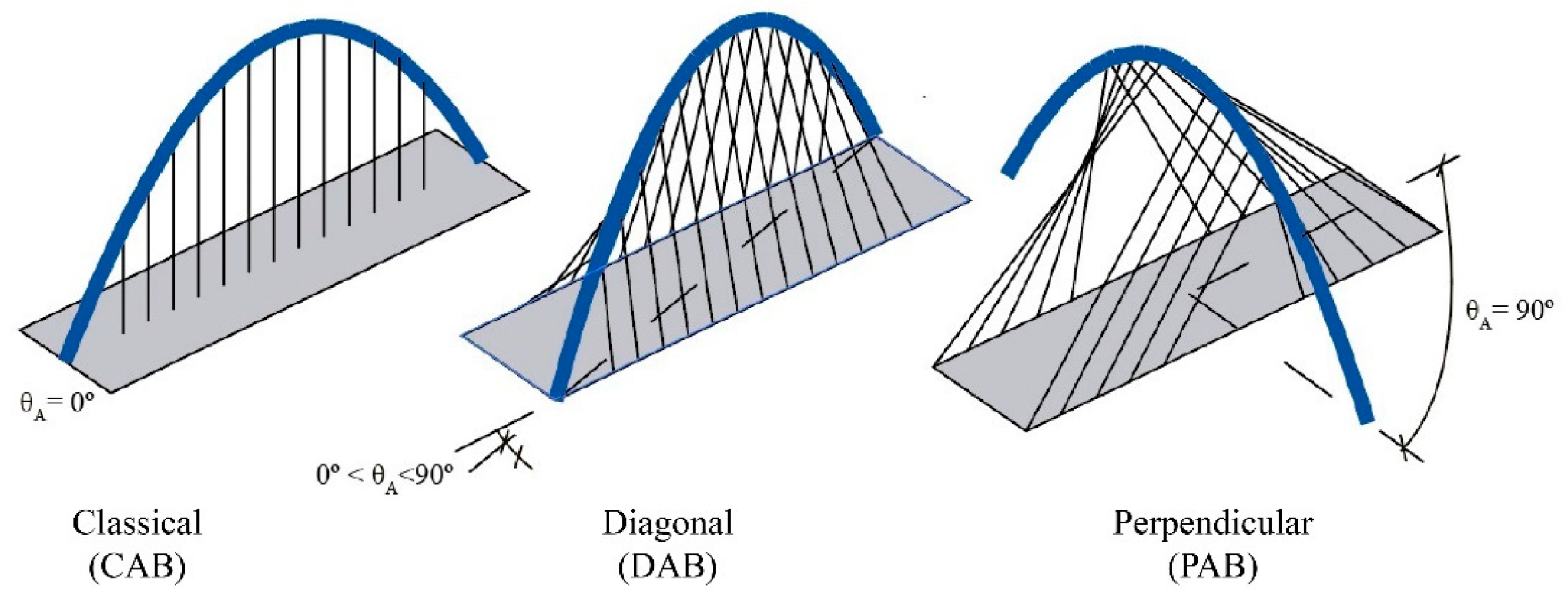
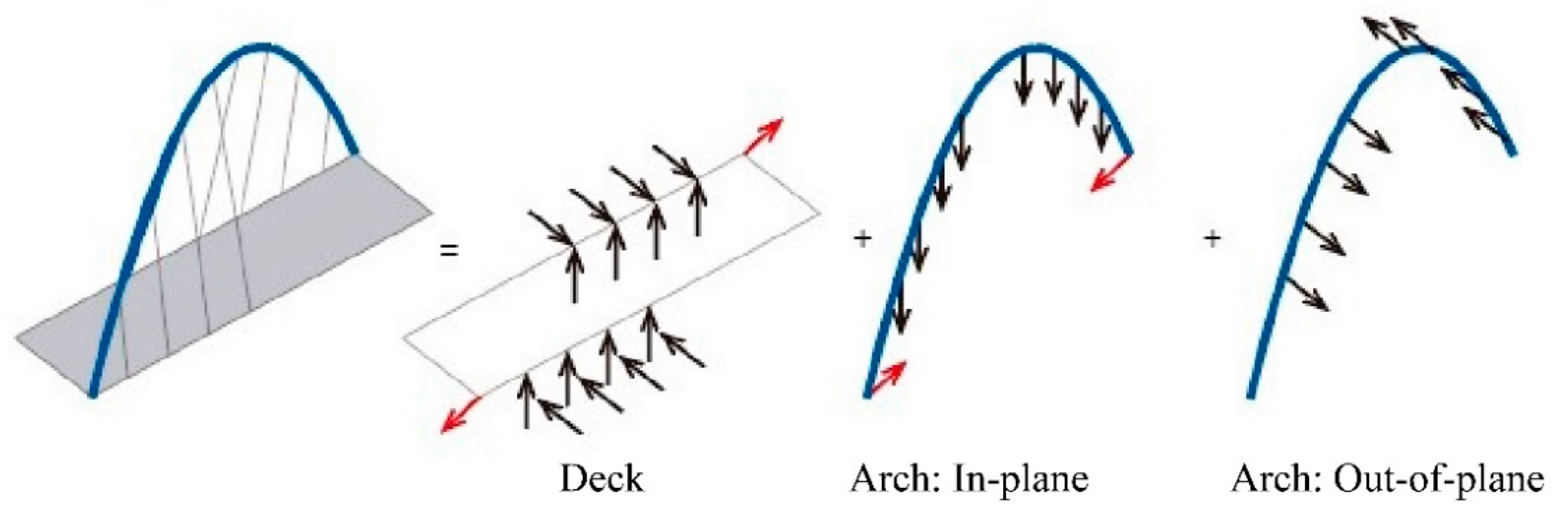
1.1. The Spatial Arch Bridge

Despite a large number of spatial arch bridges (SABs) being built in the last century, especially in recent decades, their theoretical aspects have been studied by few authors. The first comprehensive work about SABs was by Jorquera-Lucerga [1], who shows the differences on the structural response between a SAB and a “classical” vertical arch bridge (CAB), i.e., a bridge composed of a straight deck whose centerline is coplanar to the arch and is attached to its axis. In his work it is shown how, in a SAB, certain out-of-plane structural systems (such as the arch behavior as a curved beam, with coupled bending and torsion) are only present in the CAB for out-of-plane loads, whereas in the SAB they also appear for vertical loads, such as self-weight or permanent loads. For Sarmiento [2], the concept of an SAB is very similar and the concept of “non-true SABs” is also introduced. These are arch bridges that are longitudinally symmetrical in plan, but with more than one deck, one arch or one family of hangers/struts. Therefore, the spatial behavior of non-true SABs would be only activated by the eccentricity of the vertical loads on the deck or the self-weight of the inclined arches. García-Guerrero [3] studied these longitudinally symmetrical SABs (or “non-true SABs” according to Sarmiento [2]), and concluded how, frequently, the best approach to tackling specific design problems of classical arch bridges may be transforming the bridge into a spatial one. Hudecek [4] showed how the attribute that defines SABs is the presence of out-of-plane loads in the structural system. Loads applied vertically on the deck and loads resulting from the self-weight of the structure generate out-of-plane loads in the form of shear forces and bending and/or torsional moments, which may occur in all three main components of the structural system, the arch, deck, and hangers.
Considering the previous descriptions it is assumed, in this paper, that a bridge is spatial when there are vertical loads upon it that introduce out-of-plane forces in the arch. According to Jorquera-Lucerga [1], in symmetrical bridges with respect to the longitudinal plane (for example, with two vertical arches), the spatial behavior (i.e., forces not contained in the plane of the arch) appears only for some non-symmetrical load distributions. However, in a non-symmetrical structure with respect to the longitudinal plane, the spatial behavior always appears, as happens in DABs.
Thus, as mentioned in Jorquera-Lucerga [1], spatial behavior occurs mainly, but not only, due to the following causes: when the arch is rotated about a vertical axis (Figure 1a); when the arch is inclined, and rotated with respect to the line connecting its springings (Figure 1b–d); when the deck or the arch plan is horizontally curved (Figure 1b–d); when the arch is eccentrically offset with respect to the deck centerline, (Figure 1, especially Figure 1e); and when the centerline of the arch is a warped curve, i.e., the arch is not contained within a plane (Figure 1f).
Considering all the studies related with SABs, many different geometrical shapes and structural configurations can belong to this typology. This paper analyzes those arch bridges whose arch is rotated about a vertical axis, and which can be classified into two different groups—diagonal arch bridges (DABs) and perpendicular arch bridges (PABs).

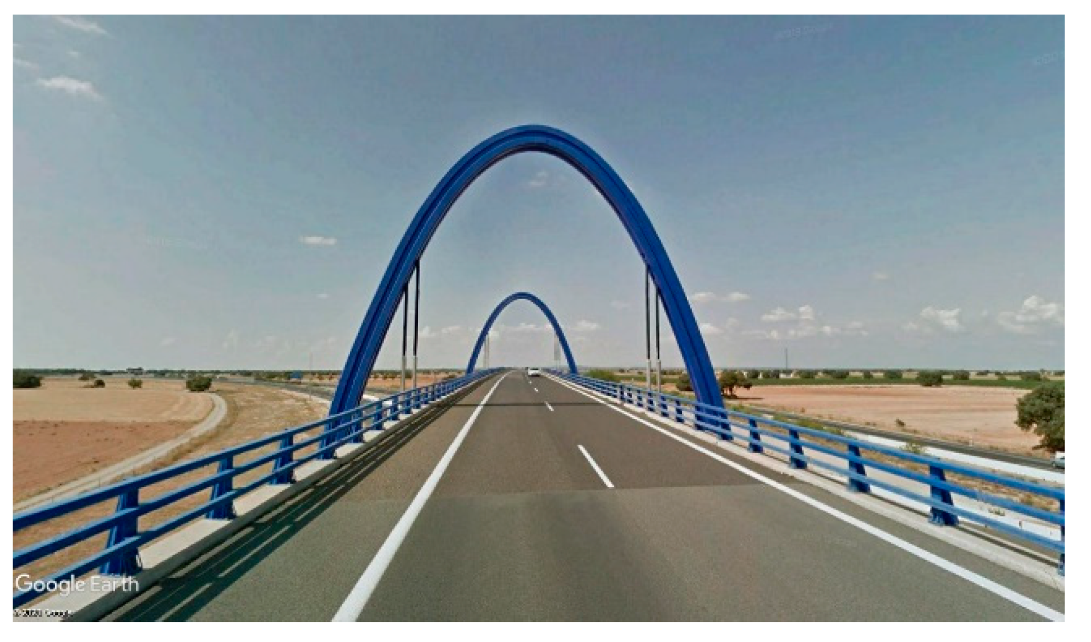
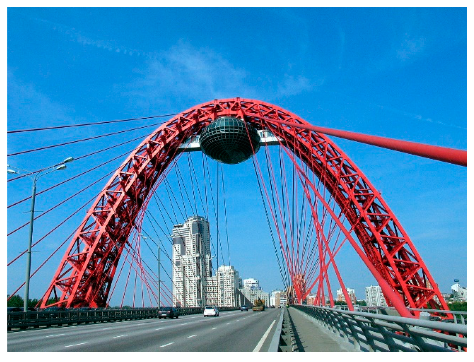
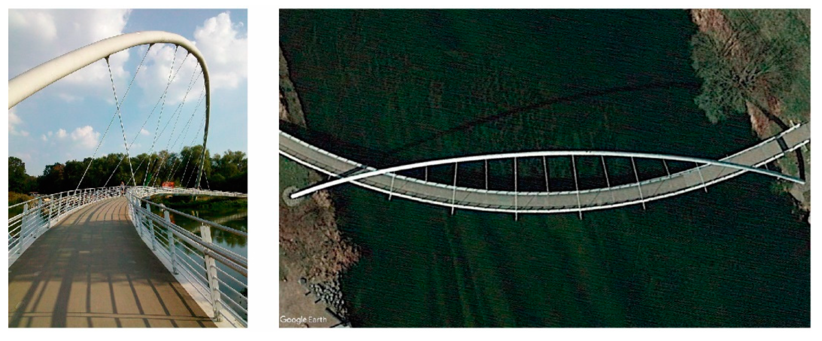
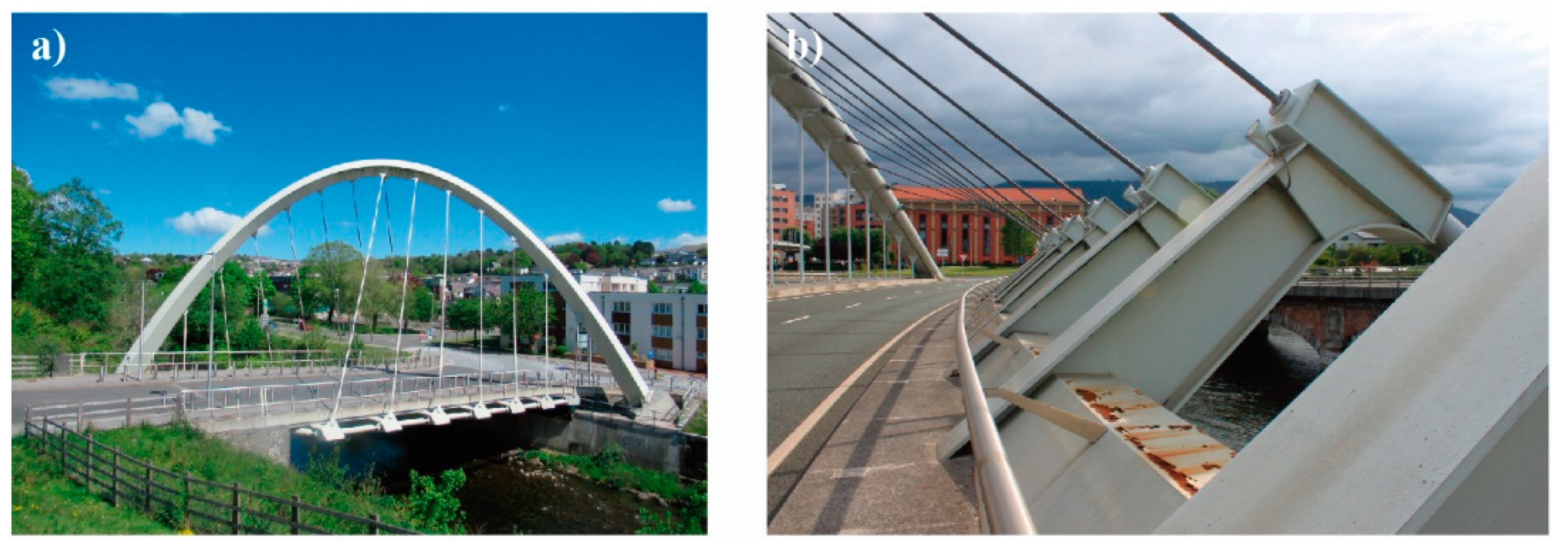
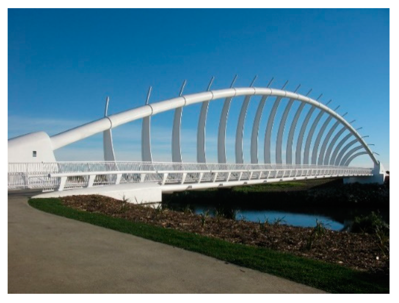
1.2. The Diagonal Arch bridge

The diagonal arch bridge (DAB) is a particular case of the SAB. The arch is rotated about a vertical axis, producing asymmetry with respect to the longitudinal plane (Figure 2). To be considered as a DAB, the angle of rotation must be between 0° and 90° and each springing of the arch must be located at a different side of the deck. This type of bridge, as explained above, have a spatial behavior for permanent loads due to its asymmetrical configuration. Normally, the abutments are perpendicular to the deck, as it is shown in Figure 2. Some authors, like Vande Walle [5], refer to the DABs as “skew arch bridges”, however, in this paper the adjective “skew” has been reserved only for bridges whose deck centerline is not perpendicular to the abutments, i.e., when the deck is skew, as detailed in Section 3.
To name just one milestone, the Hulme Arch Bridge (97d) (Figure 3) is an iconic, pioneering DAB, built in Manchester, UK, that combines architecture and engineering to produce a masterpiece (Hussain and Wilson [6]). Many related studies have been carried out to analyze in depth its structural design, construction and aesthetics, usually focusing on the orientation of the steel arch and the asymmetric arrangement of the cables that makes the structure so unique (Warren [7]). This is one of the most famous and studied DABs, and has undoubtedly been an inspiration for many subsequent projects.

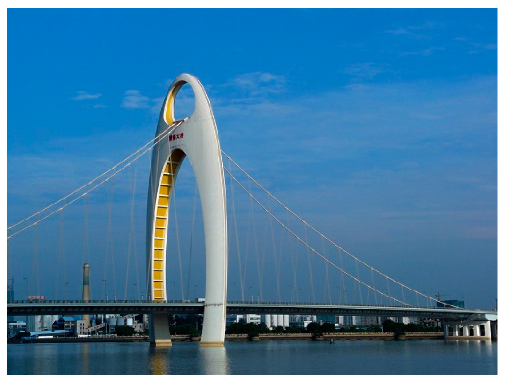
1.3. The Perpendicular Arch bridge

In the perpendicular arch bridge (PAB), the arch is rotated 90° with respect to the deck about a vertical axis that passes through the crown of the arch. In this case, the structural behavior of the arch changes radically with respect to the DAB, since the asymmetry of the bridge in the longitudinal plane disappears. In addition, due to the orientation of the arch, the out-of-plane behavior of the arch appears for longitudinally non-symmetrical distributions of vertical loads with respect to the arch. For some authors, such as Sarmiento [2], the longitudinal behavior of the PAB is, thus, similar to that of a cable-stayed bridge with an arch-shaped pylon (Figure 4).
For PABs, the cable arrangement configuration becomes extremely important due to its relevant influence on the structural behavior of the bridge and its geometry. The elevation of the arch may be parabolic, but it can be also transformed into a pointed shape depending on how the anchorages of the hangers (and subsequently, the loads transferred by them to the arch) are distributed. Shi et al. [8] present an optimization of these arch-shaped pylons for high-speed railways. It is noteworthy that Calatrava’s bridges, included in this typology, generally have pointed arches, which are elements that tend to have a structural behavior more similar to that of a tower or a pylon than to that of an arch (Figure 5). There are bridges where the loads are applied only in a concentrated area of the crown of the arch (Figure 6b), other designs have cables only at the quarter-span of the arch, whereas the most common PAB consist of an arch loaded in most of its centerline.

1.4. Recent Studies

There are relatively few studies on the structural behavior of DABs. In addition, since these studies have focused on different aspects of these bridges, the conclusions are quite heterogeneous. The first study which analyzed the structural behavior of a DAB was written by Hussain and Wilson in 1999 [6]. They described the design of the arch, the deck, the foundations, and the building process of the Hulme Arch Bridge. In 2009 Warren [7] analyzed the structural behavior of the deck of the Hulme Arch Bridge and other less-studied aspects, like temperature effects. Most studies about DABs are limited to describing actual built bridges. Although these studies provide information about the state of the art, they do not allow us to draw general conclusions about the parameters that govern the structural behavior of a DAB. Wen-Liang et al. [9] studied, in 2010, the stability of the Tong-Tai Bridge (12e), which is composed of one curved deck span, and considered, among other relevant parameters, the depth of the main girder or the vertical and lateral stiffness of the arch. Peng et al. [10] analyzed the stability of the Yueniang Bridge (11c). Wang et al. [11], compared the response of a model (geometrical scale 1:25) of the Tong-Tai Bridge with a finite element model, obtaining similar results. There are practically no studies focused on PABs. One of the few studies corresponds to Xue-jin et al. [12], which analyzed the effects of non-linear geometry on the Taijiang Bridge (10e). They concluded that the cable-sag effect should be considered when conducting analysis, and that the large displacement and beam–column effects can be ignored. As more DABs and PABs are built, more studies will hopefully be carried out, such as the one by Vande Walle [5].

1.5. Paper Structure

In Section 2 a brief historical review is provided, including examples of built and non-built bridges and the evolution of the DAB and PAB is described. In Section 3, the DAB and PAB are defined. In addition, the main parameters that govern their geometrical configuration are defined, highlighting the geometrical restrictions due to clearance requirements, which are very relevant in these bridges. This section also provides a classification for the different types of DAB and PAB, according to the previously defined parameters. In Section 4, the structural response of a CAB and a DAB are compared, the structural systems that support the loads are identified, and the most-frequent typologies for the cross-sections are justified. The paper finishes with a conclusion section. A Supplementary Materials appendix provides a table of DAB examples, sorted chronologically.

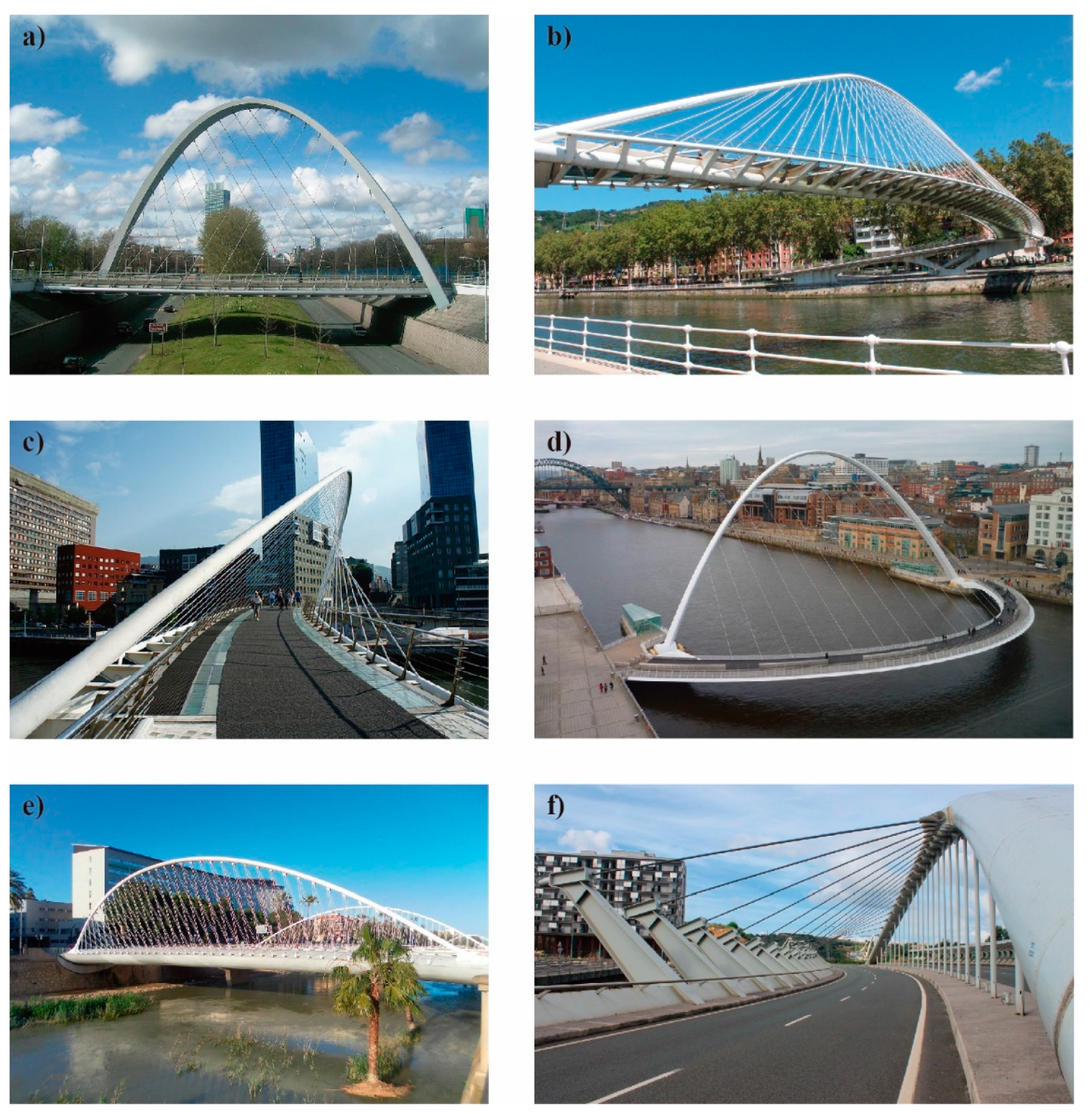
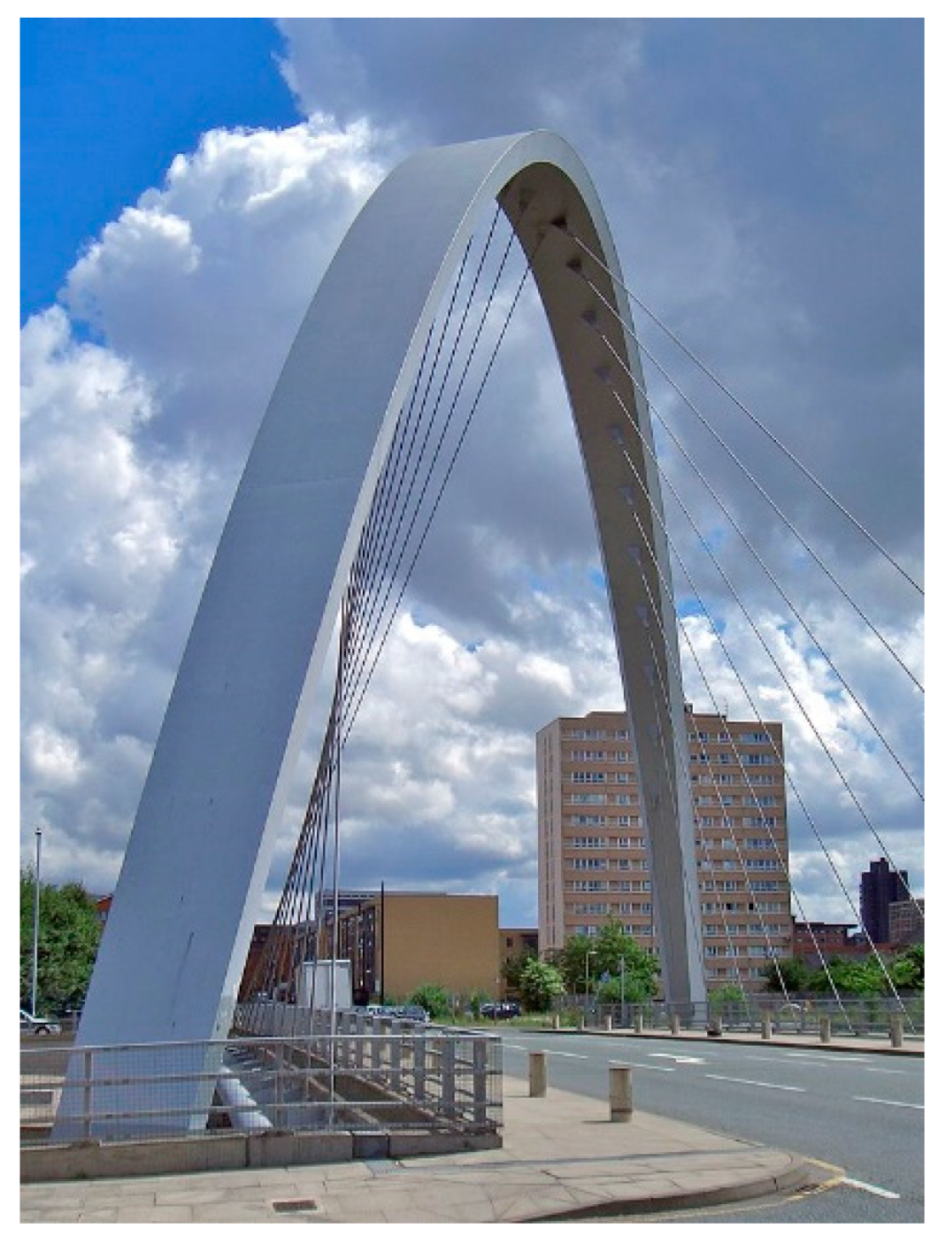
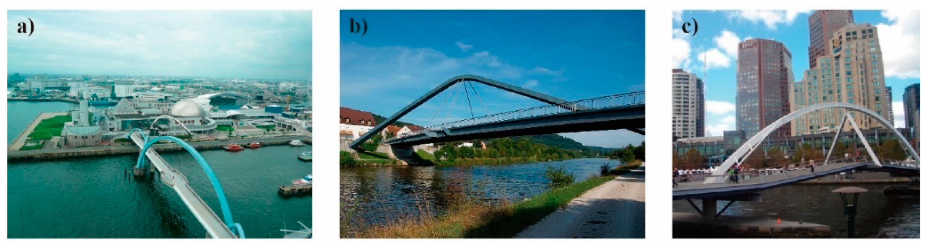
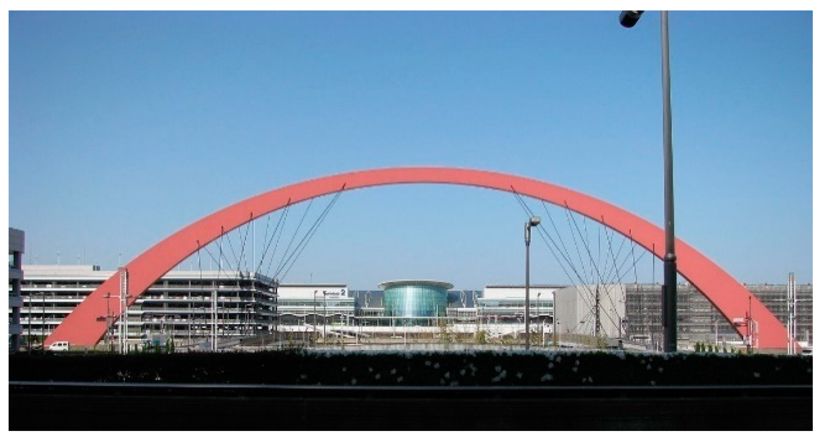
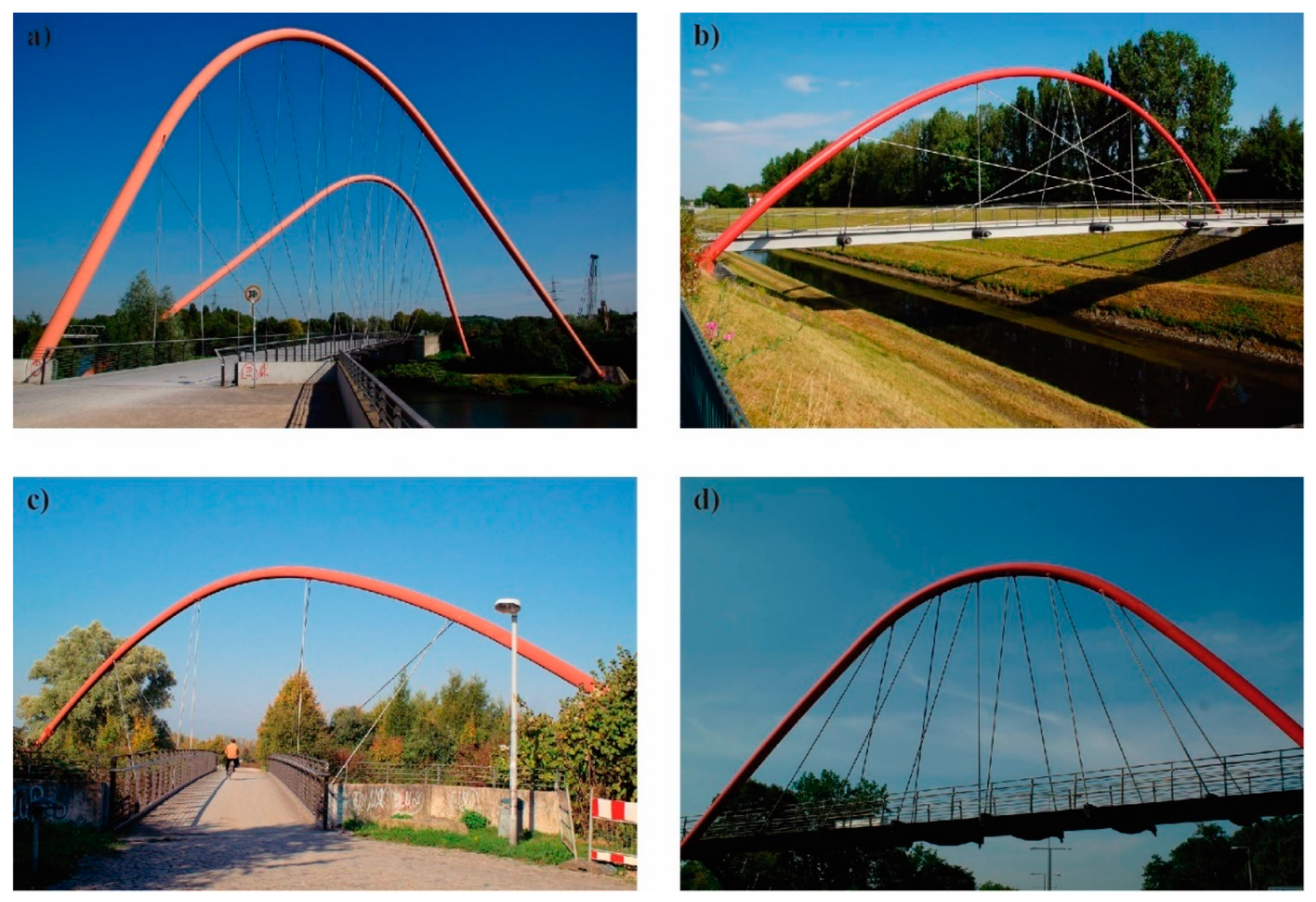
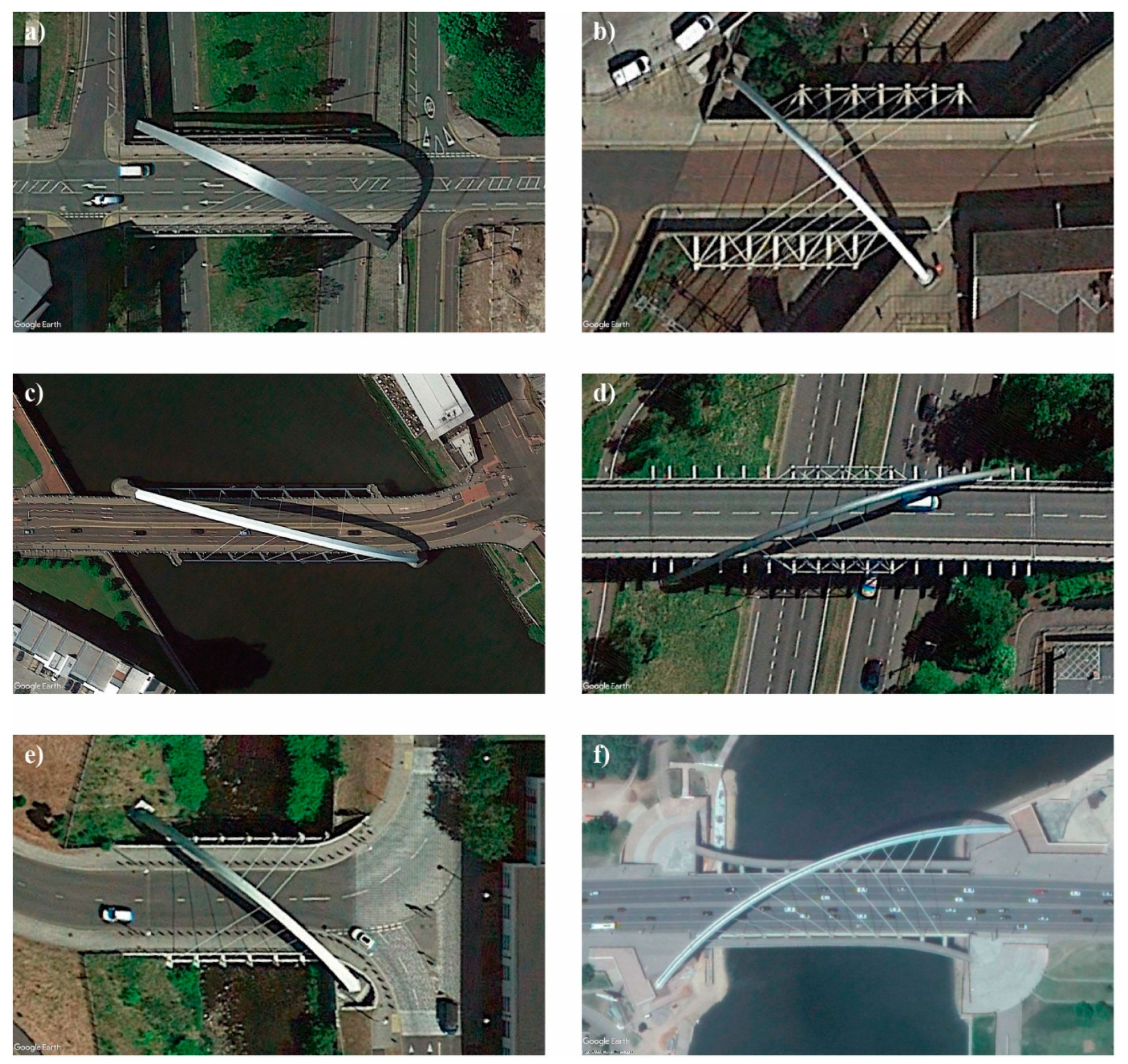
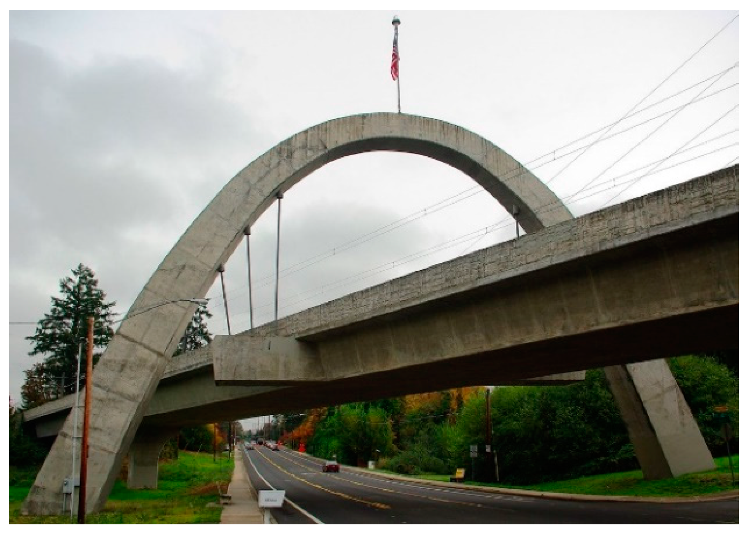
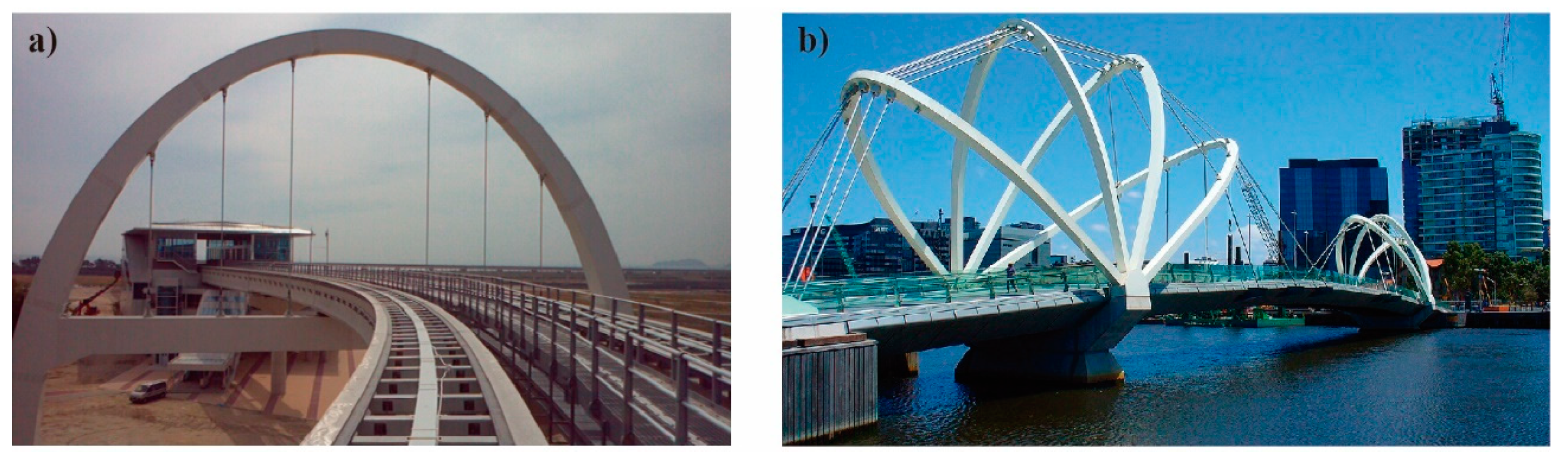
2. Brief Historical Review: Examples and Evolution

As previously described, the DAB is a particular case of the SAB. Its main characteristic is that the arch is rotated about a vertical axis passing through its crown. Due to this rotation, each springing of the arch is located in a different side of the deck. Although the SAB started to be designed in the first half of the 20th century, it was not until the end of the 1980s that the first DABs were designed. The authors consider, after an extend research and review of projected structures, that the first DAB seems to be the Nagoya Port Footbridge (89a) (Japan). In this bridge (Figure 6a), the possible interference of the hangers with the clearance are solved by suspending the deck from only two hangers attached to the crown of the arch. Even so, the deck has a circle-shaped widening at the midspan around each hanger.
The additional width of the deck is solved in different ways depending on the designers. For instance, the Plankstetten Bridge (91a) (Germany) uses two short cantilevers where the cable hangers are anchored (Figure 6b). In other cases, like the Southgate Bridge (92a) in Melbourne (Australia), the deck and the arch are linked by a triangular stiff cell attached to the crown of the arch, composed of two inclined hangers and a base wider than the deck (Figure 6c).
In 1992 the Haneda Sky Arch (92b) (Figure 7) was constructed in Tokyo (Japan). The main characteristic of this bridge is that is a PAB. In this bridge, the hangers are attached to a limited zone of the arch and are perpendicular to it, an arrangement that does not affect the clearance requirements and, subsequently, does not need additional width in the deck.
Stefan Polonyi (IPP Professor Polonyi and Partner) designed in 1996 the Nordsternpark Double Arch Bridge (96a) in Gelsenkirchen (Germany). This footbridge is made up of two parallel diagonal arches, the first bridge being where the additional width of the deck extends over the entire span, and the cross sections are circular, hollow sections made out of structural steel. Similar bridges, such as Lehrhovebruch Footbridge (96b), Nordsternpark Arch Bridge (97a), and TZU Footbridge (97b) (which has a curved deck), can be attributed to the same designer. All of these are pedestrian bridges in Germany (Figure 8).
The construction of the Hulme Arch Bridge in Manchester (England) meant “a landmark structure which captures the public’s imagination” (Hussain and Wilson [6]). The best contribution of this bridge is the rationalization of the cable arrangement through a unique set of asymmetrical hangers. Bridges built before the Hulme Arch Bridge follow irregular and sometimes chaotic cable arrangement patterns, which give the idea of random distributions. This bridge was the inspiration for later bridges, such as the Newport Street Bridge (05a) in Bolton (England), the Clyde Arc (06a) in Glasgow (Scotland), the Gogarburn Bridge (06b) in Edinburgh (Scotland), and the River Taff Central Link Bridge (14a) (Figure 9).
After the construction of the Ramstore Bridge (08a) in Astana (Kazakhstan), the distribution of widenings was improved through the span of the deck, changing from constant to variable distributions in new bridges.
It seems the first diagonal railway diagonal arch bridge constructed was the Hillsboro Main Street Bridge (97e) in Oregon (USA) (Figure 10). To the authors’ knowledge, this bridge is today a unique DAB where the arch is totally made out of reinforced concrete. Similarly, it is noteworthy that the overpass (06f) in the AP-36 highway in La Roda (Spain), since it is the first steel arch filled with concrete [13] (Figure 11), a diagonal version of a CFST (concrete-filled steel tube).
The first bridge with more than one arch was the Nagoya Port Footbridge (Japan), but only one of the six arches has a clear structural function. Thus, the first real DAB with continuous arches can be considered the Juscelino Kubitschek Bridge (02a) in Brasilia (Brazil) (Figure 12), however, the arches do not present a real continuous structural behavior since the deck is supported by columns situated between the springs of adjacent arches. It is noteworthy the Juscelino Kubitschek Bridge is the longest DAB with 240 m of span [14].
On the other hand, the PAB with the highest arch is the Zhivopisny Bridge (07a) in Moscow (Russia) (Figure 13), with a height of 105 m. This bridge is also a singular structure, since under the crown of the arch there is a disc-shaped structure which is used as a restaurant.
Nowadays the design of diagonal arch bridges presents two main and opposed trends. On the one hand, the design tends to improve the structural performance of the DAB, as described, for example, in the work of Jorquera-Lucerga [1]. An example of design focused on the structural efficiency of the diagonal arch is the proposal by Schlaich, Bergermann and Partner for a Footbridge in Deizisau (05f), where the shape of the arch is a three-dimensional antifunicular form [15]. Similar innovative bridges are the proposals for the Nine Elms Bridge (15b), from the same designers, and for the Salford Footbridge (14h) (Figure 14), by José Romo [16].
On the other hand, the designs focus on aesthetics, a priority that generally leads to inefficient solutions from a structural point of view. Some examples are the Fukuyama Dongguan Bridge (18c), the Incheon Maglev Arch Bridge (14d), and the Seafarers Bridge (09c) (Figure 15).

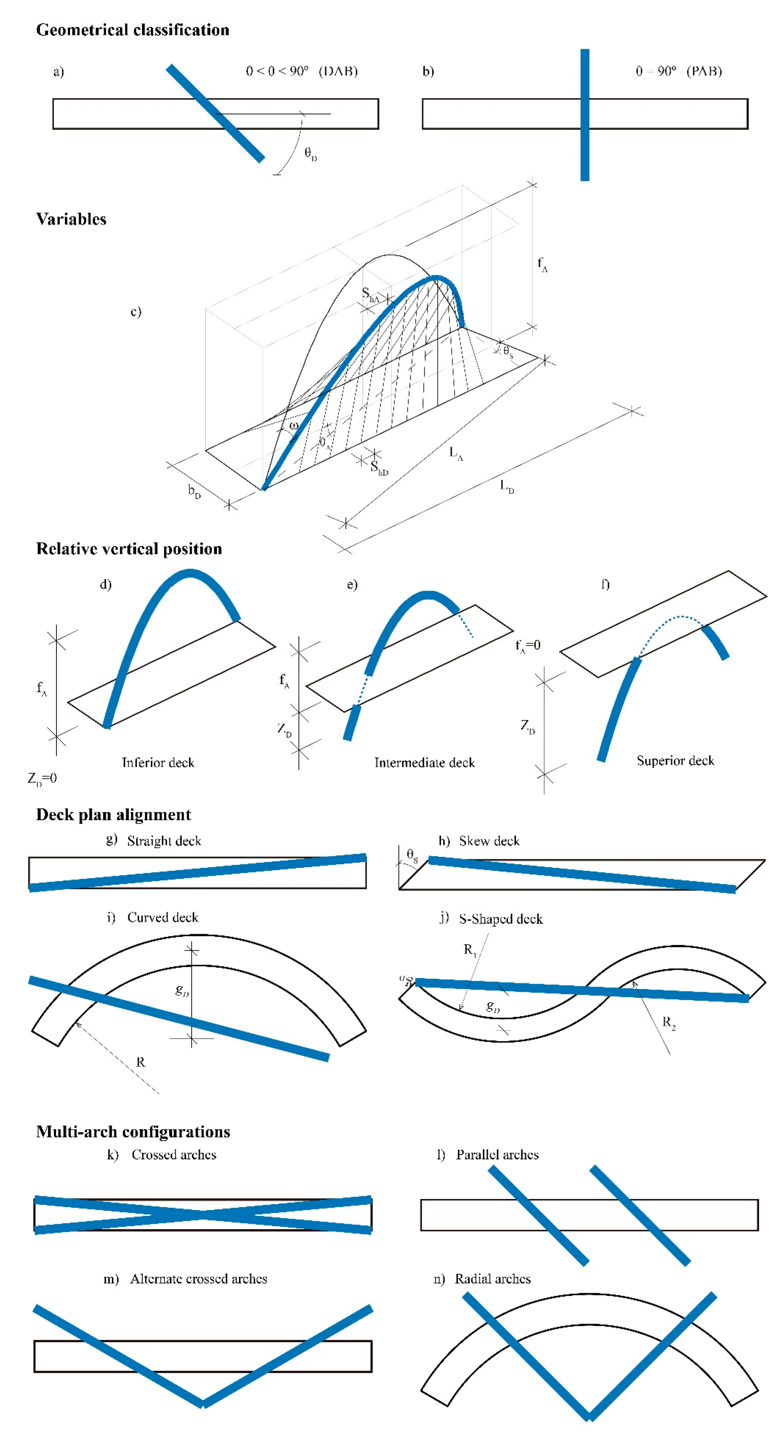
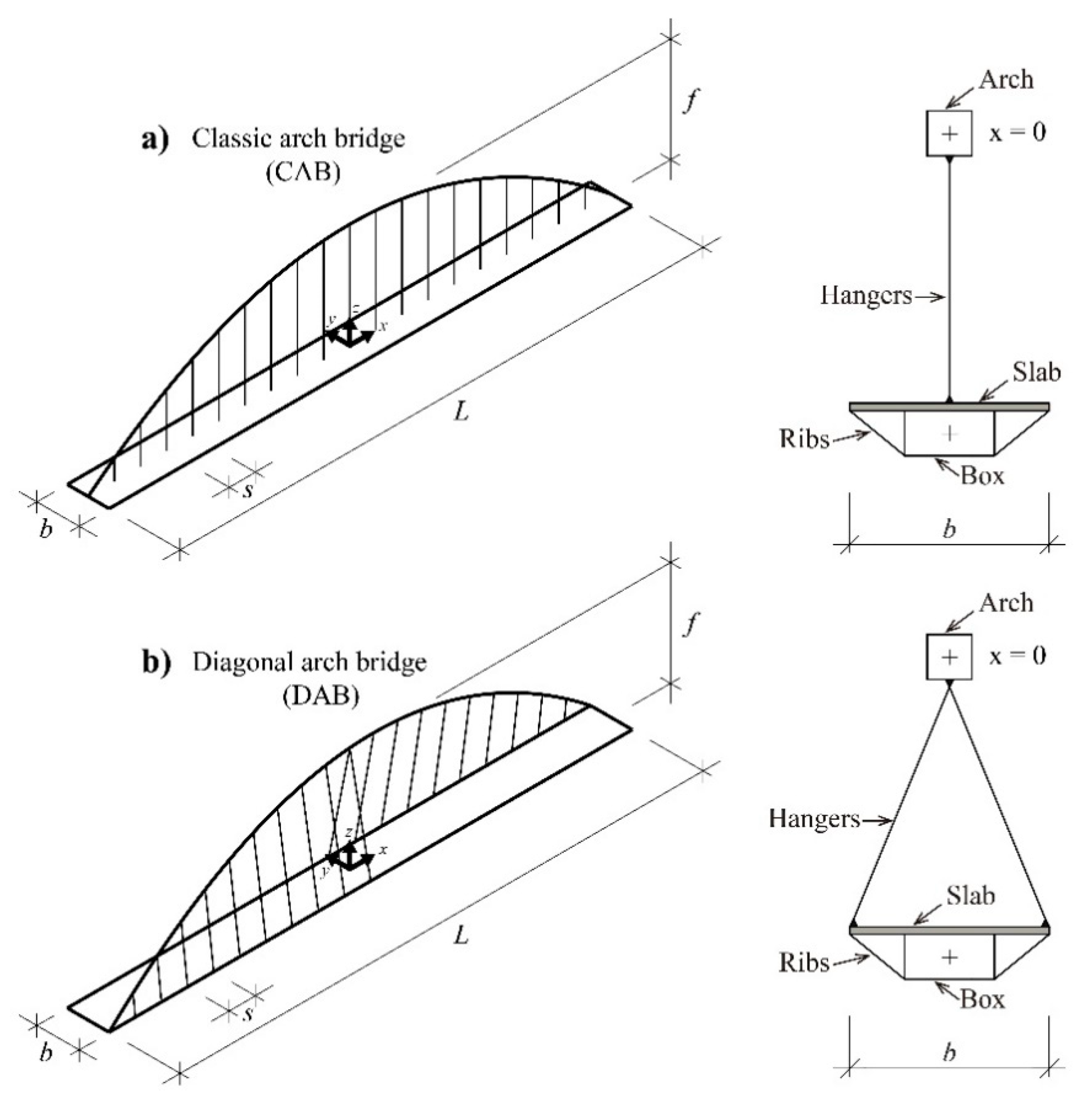
3. Definition and Typological Classification

3.1. Definition

The Diagonal arch bridge is a particular case of the spatial arch bridge, where the arch is rotated about a vertical axis, so that each springing of the arch lies in a different side of the deck. The angle between the arch and the deck centerlines, θA (Figure 16), is the main parameter that structurally and geometrically defines the bridge. Obviously, when θA = 0°, the arch is not rotated, and the bridge is a classical arch bridge (CAB). The bridge can be classified as a DAB for 0° < θA < 90°, provided each spring is located at a different side of the deck. For a bridge to be included as a DAB, this criterion is crucial. The criterion, is fulfilled¸ for example, by the Pont André-Bord (17a) (Figure 17), in contrast to the Tiergartenbrücke (Figure 18).
Applying that criterion, the Tiergartenbrücke (Figure 18), the Slodowa Island Footbridge (Figure 19a), the Pont de l’Observatoire (Figure 19b), and the Ripshorst Footbridge (Figure 19c) should not be classified as a DAB, because, although the decks are supported from rotated arches, both springings are on the same side of the deck. These bridges are, therefore, beyond the scope of this paper.
When θA = 90° (Figure 16), it might seem at first glance the bridge should be classified as a DAB, since the arch is rotated with respect to a vertical axis and the springs of the arch are situated on different sides of the deck. However, this particular case is defined as perpendicular arch bridge (PAB), because its structural behavior is substantially different from that of a DAB. Some studies classify this bridges as cable-stayed bridges with arch-shaped pylons (Sarmiento [2]), although the authors find this analogy might not be totally correct, since the arch has the typical behavior of a curved element, with a structural response which is different from that of the usual pylons (A-, H-, or Y-shaped pylons, among others) used in cable-stayed bridges, as described, for example in Leonhardt [17] or Svensson [18]. However, it is true that in most typological classifications borders are blurred—for example, the Liede Bridge in Guangzhou, China (Figure 20) is an example of pylon whose behavior is more similar to that of a suspension bridge tower than that of an arch bridge. Consequently, these bridges are beyond the scope of our study and have not been considered as PABs.

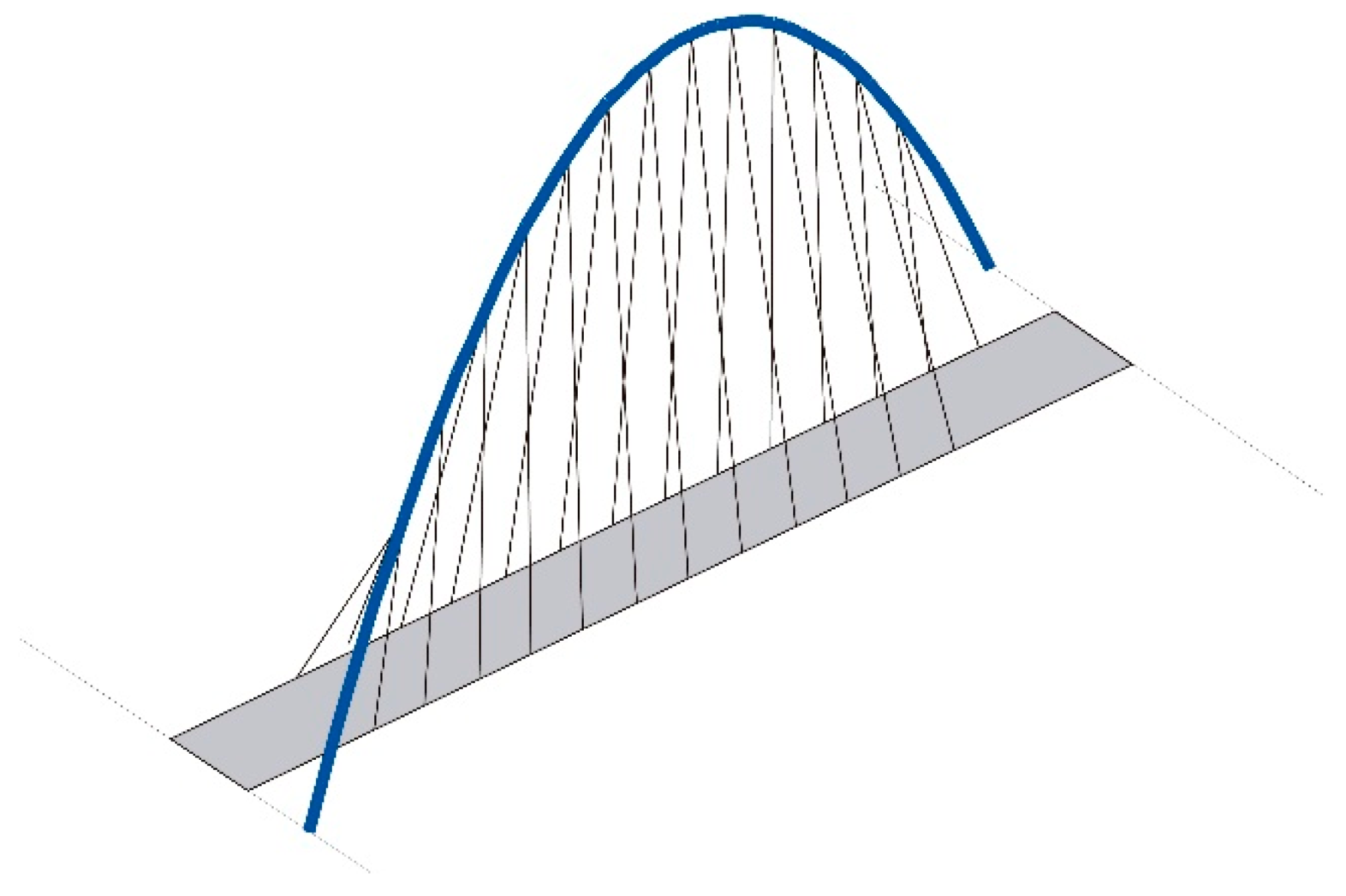
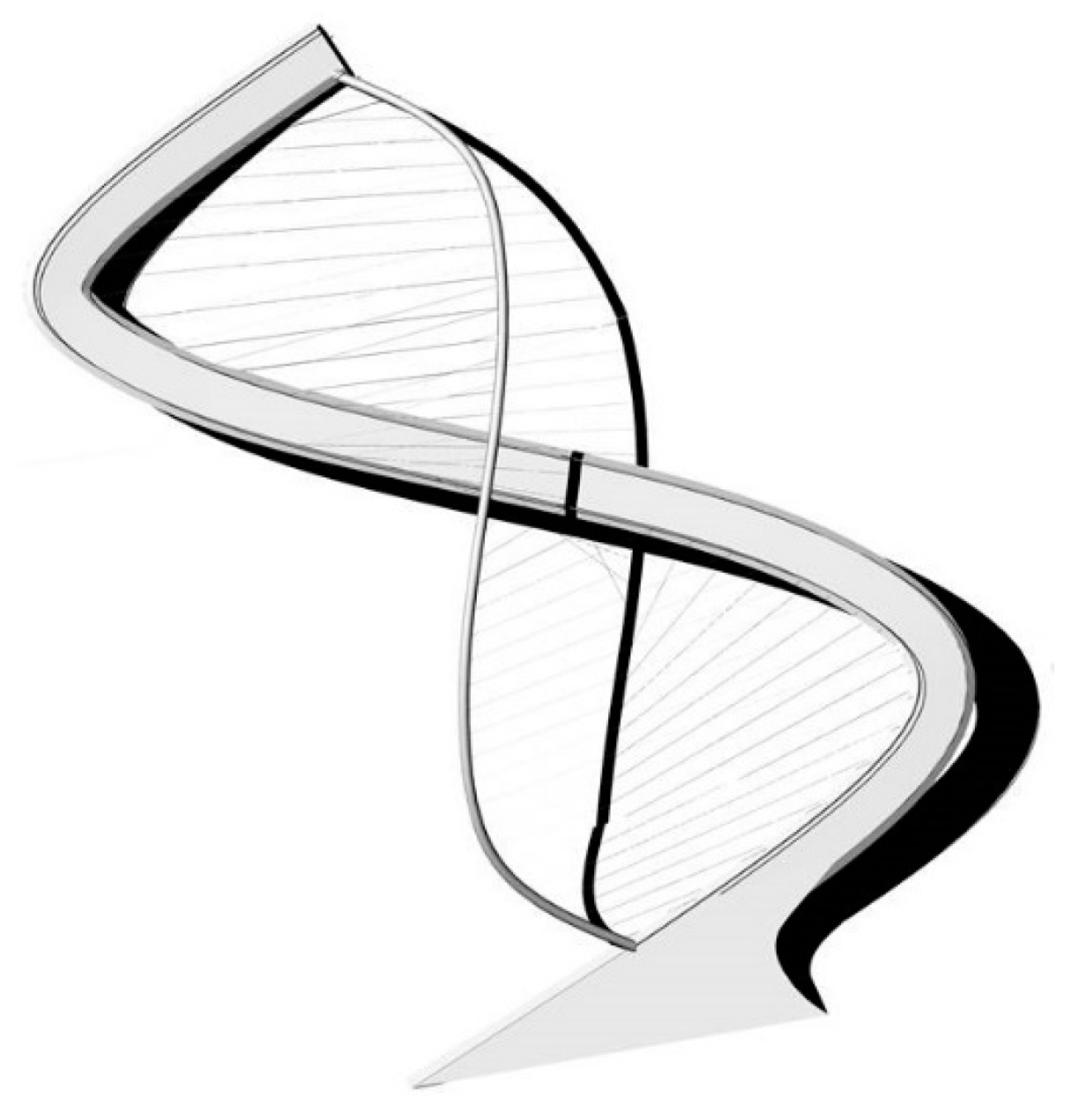
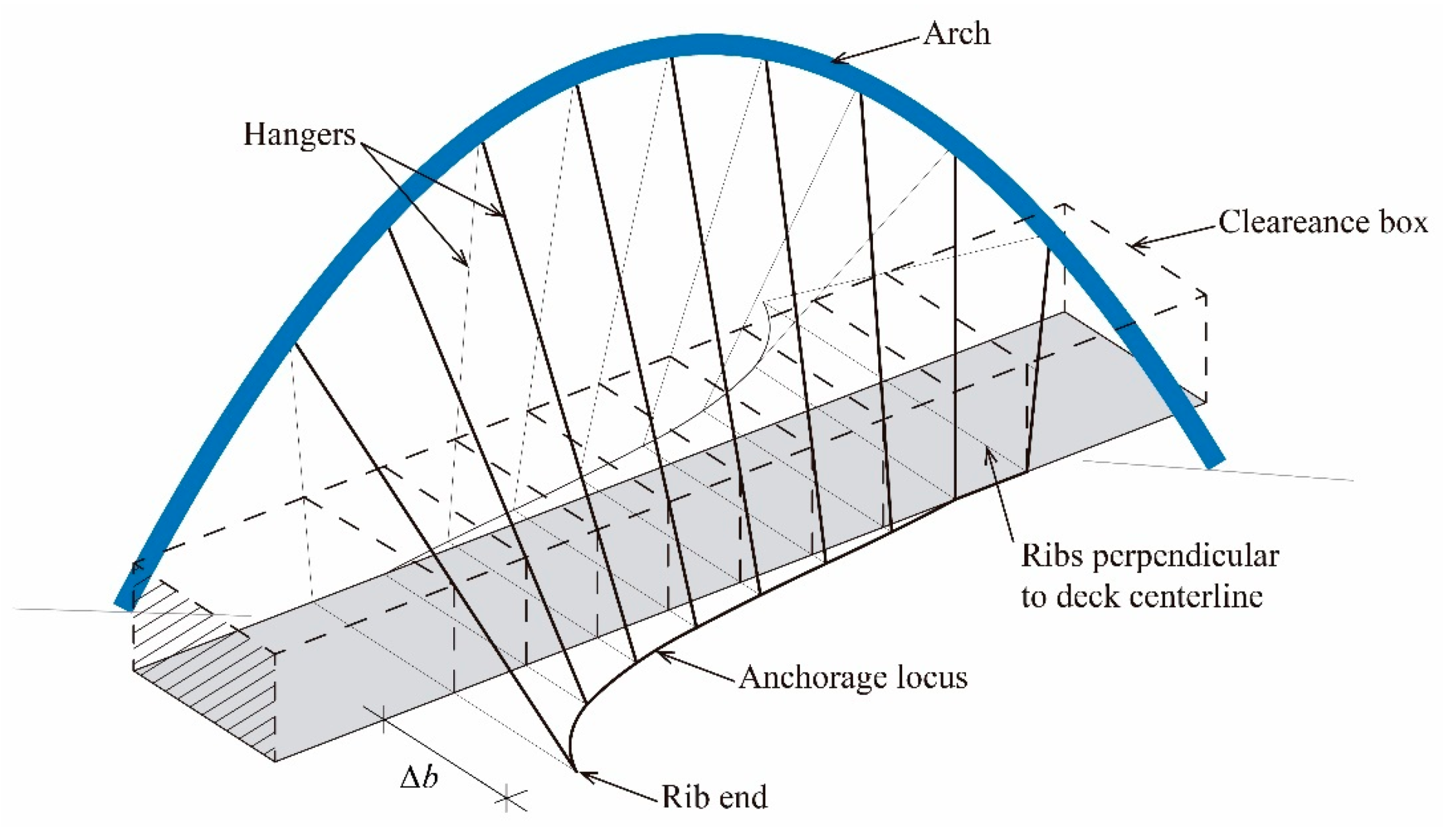
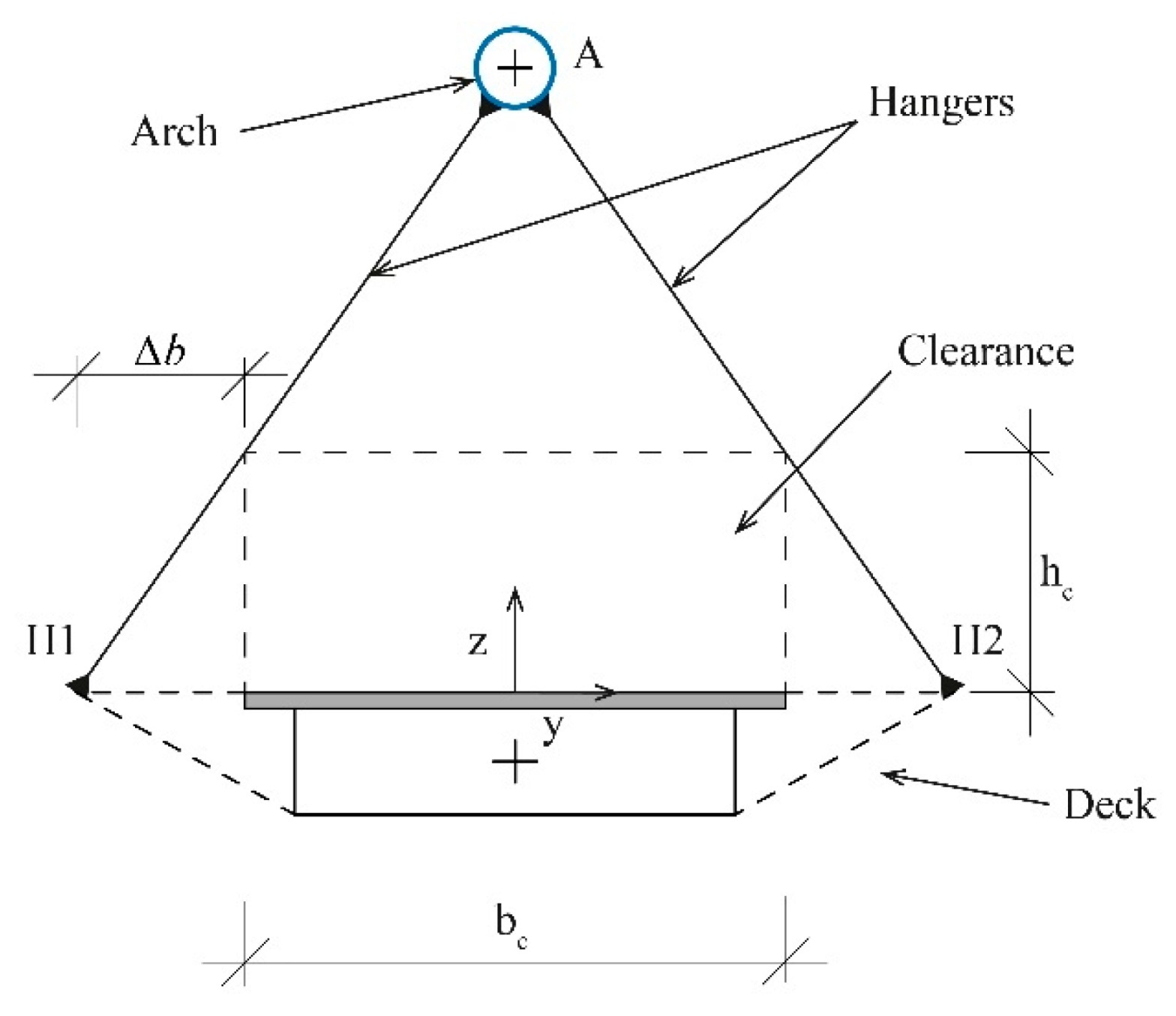
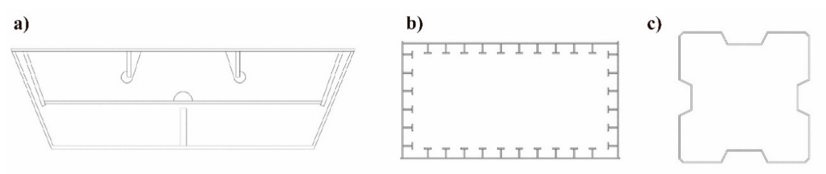
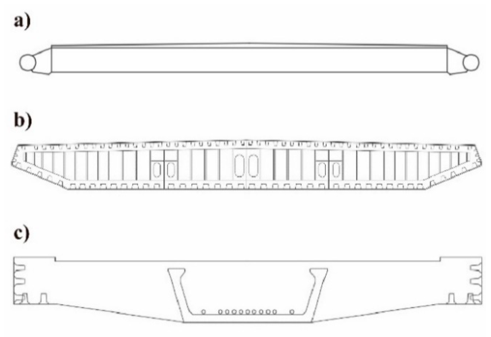
3.2. Main Geometrical Variables

The arch is the structural element that characterizes the bridge. Its structural performance consists of supporting the loads applied to the deck (through cable hangers), transmitting them to the foundations. The most common geometries used to define the centerline of the arch are the parabola, the catenary, and the circular arc. The arch is defined by the following parameters (Figure 21c):
  • LA: Span of the arch, defined as the length between the springs of the arch.
  • fA: Rise of the arch in the vertical plane. Despite the plan of the arch is diagonal, its elevation has a vertex at the crown of the arch (0, fA) and passes through its springs (-LA/2, 0) and (LA/2, 0).
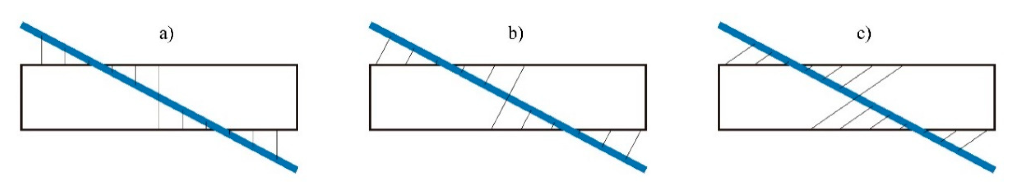
  • θA: Arch rotation angle, or angle between the horizontal projection of the centerline of the arch and the deck. θA = atan(b/L) when the arch crosses the deck diagonally.
  • ω: Inclination of the plan of the arch with respect to the vertical plane.
The geometry of the deck, including horizontally curved decks, is defined by the following parameters (Figure 21c):
  • LD: Span of the deck.
  • bD: Width of the deck.
  • θS: Angle of skew of the deck. Angle between the axis of the deck and the line of supports.
  • gD: Horizontal sagitta of the horizontally curved deck (Figure 21). For S-shaped decks, gD changes its sign when the curvature of the deck changes.
  • R: Radius in the deck axis, for curved and S-shaped decks (Figure 21).
The hangers are the structural elements that link the arch and the deck, transferring the loads from the deck to the arch. Hangers can be defined by the following parameters (Figure 21c):
  • shD: Distance between hangers measured in the deck plan.
  • shA: Distance between hangers measured over the developed length of the arch.
The relative arch-deck position, as it happens in all the arch bridges, can be (Figure 21d–f):
  • ZD = 0, inferior deck.
  • fAZD > 0, intermediate deck.
  • ZDfA, superior deck.

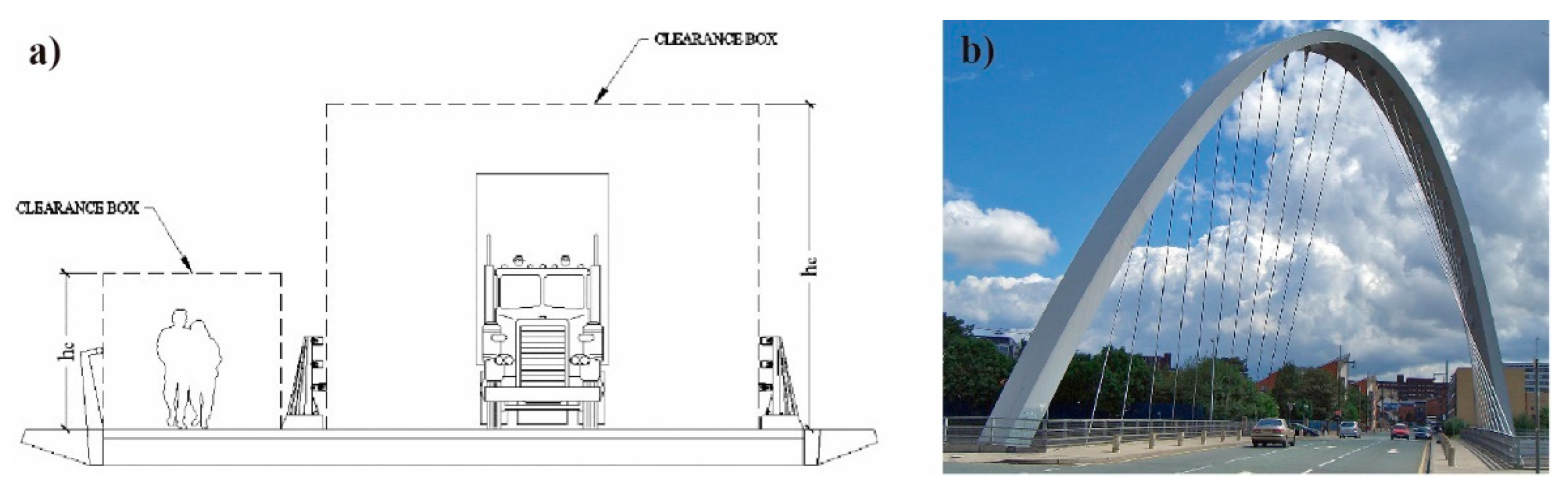
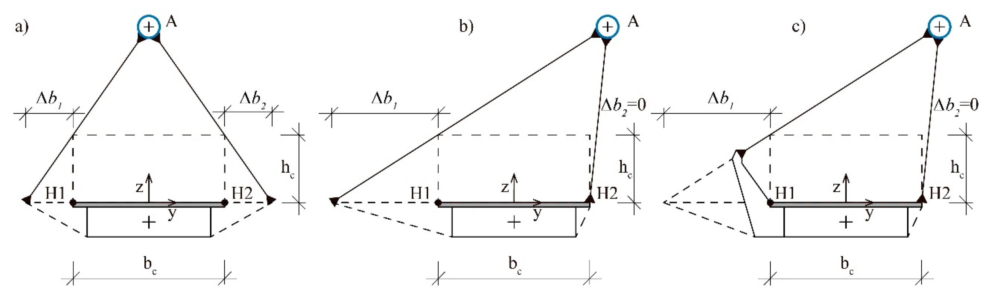
3.3. Clearance Requirements

As in any other bridge, in a DAB it is absolutely essential to respect the clearance restrictions to allow vehicle and pedestrian traffic (Figure 22a). However, in a DAB the problem requires special attention due to the arrangement of the cables, which are usually inclined, a situation that often leads to the need of additional width of the deck (as it happens, for example, in the Hulme Arch Bridge, Figure 22b) to allow enough room to anchor the hangers without interfering with the clearance of the deck (Figure 23).
Figure 24 shows a generic symmetrical cross-section of a DAB, that corresponds to the midspan cross-section of the bridge defined in Figure 23. The height and the width of the clearance box of the deck are hc and bc, respectively. The hangers connect the arch to the edges of the deck (Points A and H, respectively). Due to the clearance requirements, the deck needs additional width, Δb, at each side of the deck, with respect to the width imposed by strict clearance restrictions.
Figure 25 shows the different possibilities that may arise when, in the cross-section, the arch is not located exactly over the axis of the deck. The case of Figure 25a is very similar to that of Figure 24, except that the additional widening needed at each edge, Δb1 and Δb2, are different. In the case of Figure 25b, an additional width is necessary in only one edge. Figure 25c shows how hangers can also be anchored to rigid elements protruding from the deck. For a given geometry of the arch and the deck, the additional widths, Δb1 and Δb2, can be easily obtained at each cross-section by similarity of triangles. There are many different structural systems to provide the additional width of the deck. Cantilever additional ribs, perpendicular to the deck axis, are a very common solution (Figure 25b and Figure 26a). The cables can also be attached to inclined stiff elements protruding from the deck (Figure 16 and Figure 25c).

3.4. Tied Diagonal Arch Bridge

In a similar way to classical arch bridges, the arch can be connected to the ends of the deck. Thus, the deck is tensioned under the horizontal thrust transferred to its ends at both springings of the arch. Then, the DAB transforms into a tied DAB, i.e., a diagonal version of a tied arch bridge, also known as bowstring, where the tension axial force of the deck is oriented diagonally, coinciding with the shadow of the arch over the deck (Figure 27a). The main advantage of these bridges, as in classical tied arch bridges, is that the arch does not transfer horizontal forces to the foundations.
Obviously, the tied DAB is only possible when the arch springing can be physically connected to the ends of the deck. When this it is not possible, as happens in Figure 27b, the foundations must support the horizontal reactions due to the arch compressive force. This configuration is, in general terms, more expensive that the tied DAB, because separate foundations must be provided both for the arch and the deck, now detached, which are also now subjected to higher loads.

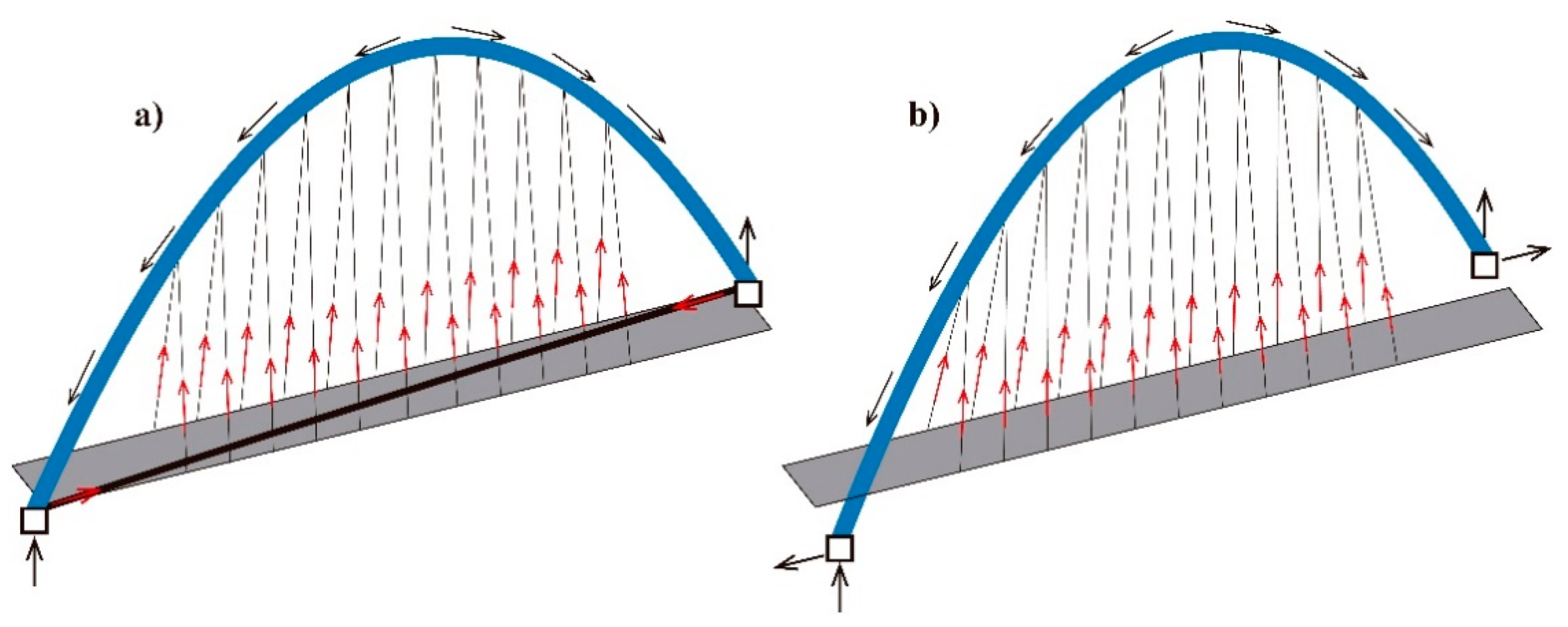
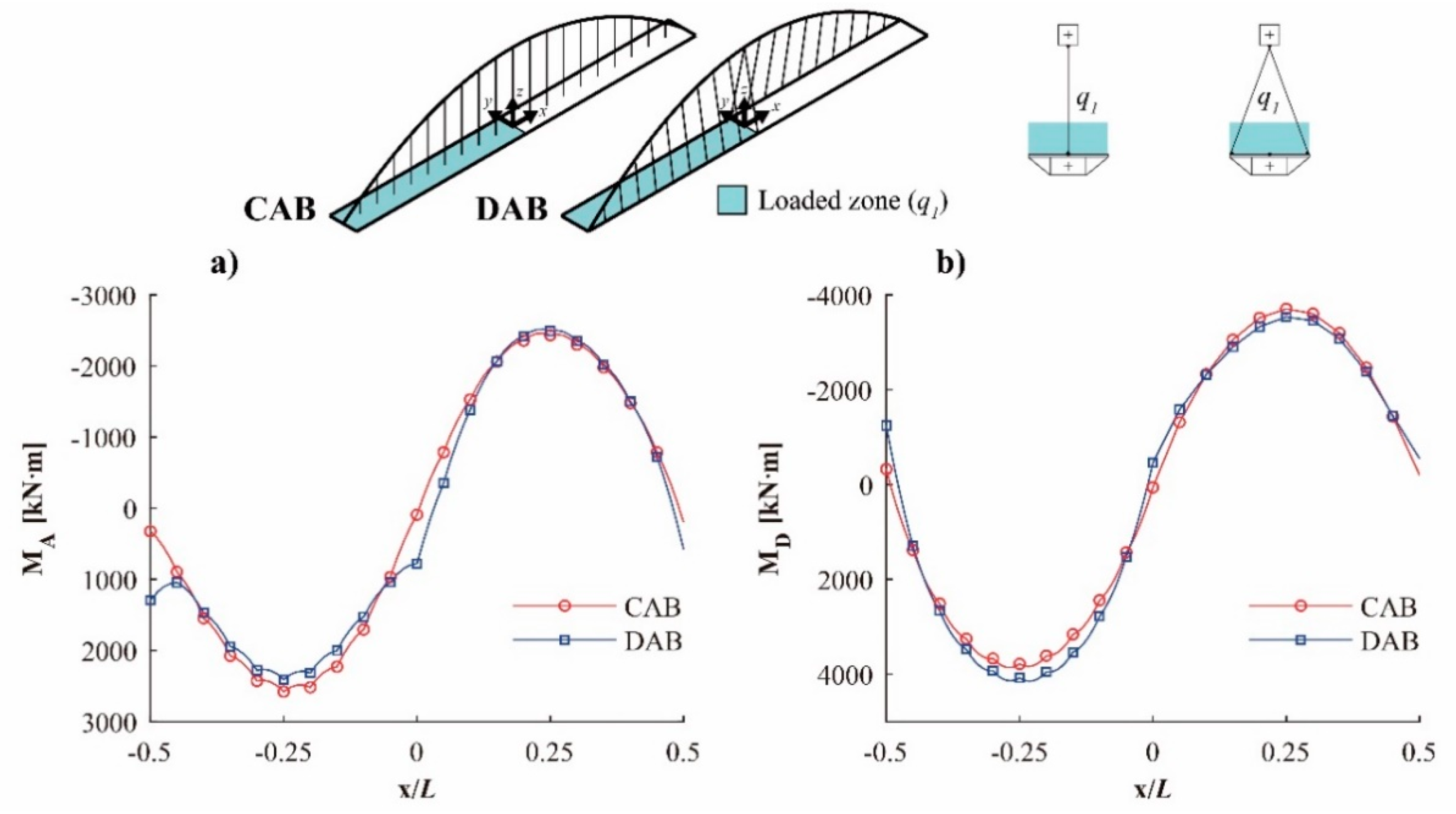
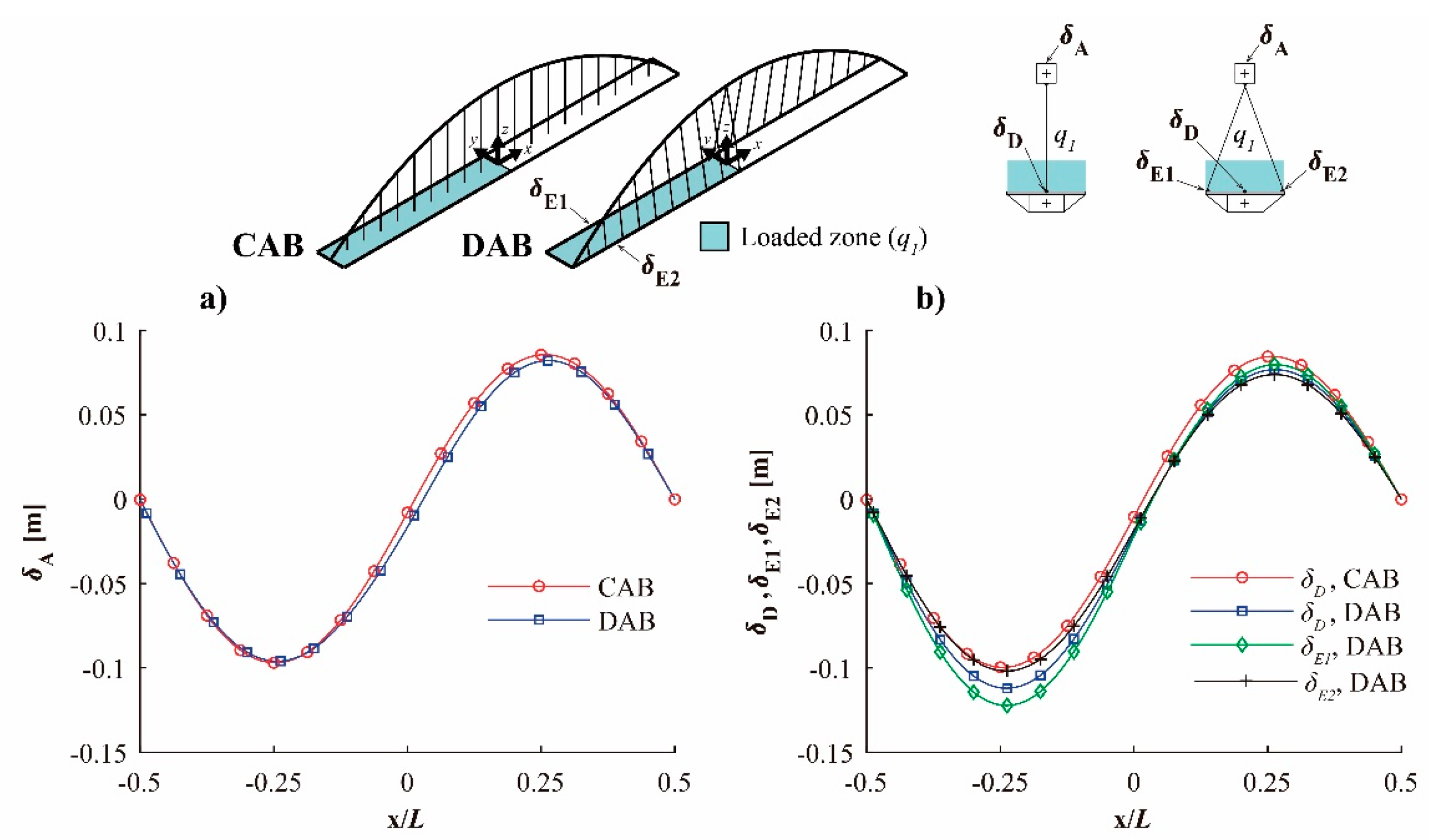
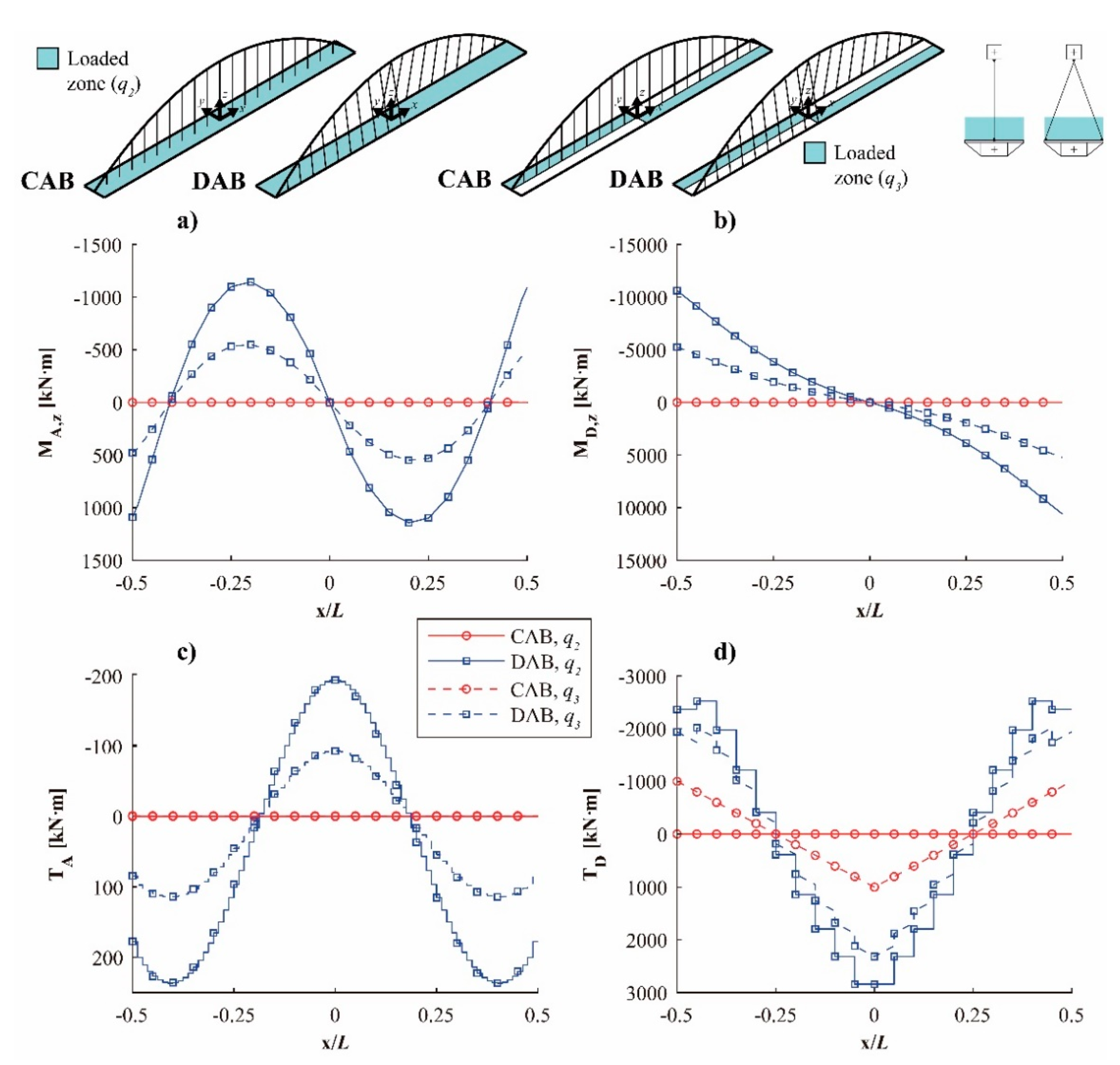
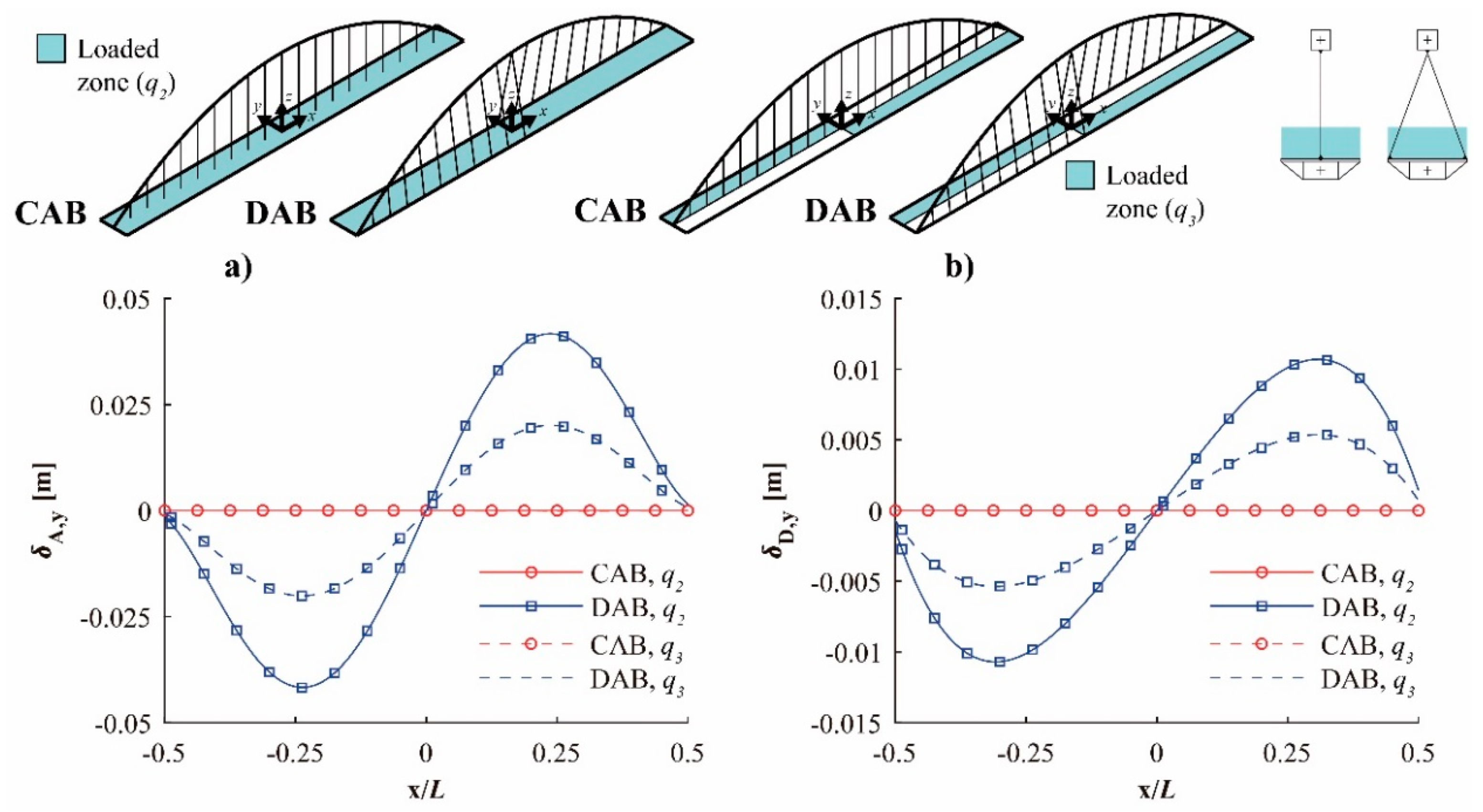
4. Structural Behavior

One of the main features of SABs is that there are certain structural systems that remain inactive in a CAB but are activated for spatial configurations. In the particular case of DABs, the two bridges shown in Figure 28 have been compared to illustrate this fact. The main difference between the two bridges is that in the CAB (Figure 28a) the arch is aligned parallel to the centerline of the straight deck, whereas in the DAB (Figure 28b) the arch spans diagonally over the deck. Besides, in the DAB, due to the above-mentioned clearance restrictions, the hangers have been attached to one edge of the deck. Of the two possible hangers attached to the same point of the arch, the steeper one has been selected at each point, which causes the antisymmetrical distribution shown in the figure.
Both bridges have a span, L = 100 m, and a rise, f = 20 m. The spacing between anchorages of the hangers in the deck is s = 5 m. The loaded width of the deck is b = 8 m. The cross-section of the arch is assumed to be an all-steel hollow-box section, whereas the cross-section of the deck is assumed to be a composite steel–concrete section composed of a steel box-section and a reinforced concrete slab. Each end of the arch is fully fixed to the deck. It has also been assumed that the box has transverse ribs, although they have no influence on the overall structural behavior. The self-weight of the concrete slab has been considered as part of the permanent loads, and the mechanical properties of the cross-section of the deck are, in a simplified way, assumed to be those of the hollow all-steel box cross-section described in Table 1. These dimensions are inspired by real arch bridges and are relatively common (see, for example, Leonhardt [17] or Lebet and Hirt [19]). Their dimensions are shown in Table 1.
With the objective of illustrating the studied structural behavior, the following load cases have been considered in this study:
  • The self-weight (SW) of the bridge, evaluated for a specific weight of 78.5 kN/m3, and a dead load (DL), with a value of 3 kN/m2.
  • Three downward pedestrian live loads distributions, q1, q2, and q3, which correspond to the LM-4 load model defined in Eurocode 1-2 [20] (Figure 29).
The response of the bridges has been determined by applying the finite-element method. For this purpose, linear elastic analyses have been carried out under static loads. The models are three-dimensional, with six degrees of freedom per node, and are composed of linear members (“frame elements” in SAP2000 [21]).
With respect to the in-plane bending moments’ longitudinal bending (Figure 30), the behavior of bridges such as the CAB is well known, and the most adverse load case corresponds to q1 (Figure 29). The in-plane bending moments in this bridge have the well-known S-shape both at the arch (Figure 30a) and the deck (Figure 30b). The longitudinal bending in this bridge is defined by the projection of the axial forces of the hangers on the plane of the arch, i.e., in this case, their vertical components. The same occurs in the DAB, and the distribution of bending moments in the DAB in this case is very similar to that of the CAB.
Since the in-plane bending moments in the arch are very similar in the CAB and DAB, the vertical deflections are also similar (Figure 31a). However, the vertical deflections are larger in the DAB deck (Figure 31b), since each cross-section of the deck of the studied DAB is supported by only one hanger anchored at one of its edges.
Figure 32 shows the out-of-plane bending moments in the arch and in the deck under the loads q2 and q3. These out-of-plane bending moments does not appear in the CAB and are produced by the transversal components (perpendicular to the plane of the arch) of the axial forces at the heads of the hangers (Figure 33). Its antisymmetrical shape is due to the fact that those transversal components of the axial loads at the heads of the hangers change their orientation as the bridge is crossed. The out-of-plane bending moments in the deck (Figure 32b) have the same origin, although the sign of the bending moment is inverted with respect to that of the arch because the orientation of the transversal components of the axial loads of the hangers (perpendicular to the deck) is reversed at the bases of the hangers (Figure 33).
As happens in any curved structural element, the torsion appears because of the coupling with out-of-plane bending (Figure 32c). The origin of the torsion at the deck is different (Figure 32d), and it is caused because, in the studied bridge, the hangers are anchored to only one edge of the deck.
Figure 34 shows the transversal deflections both in the arch (Figure 34a) and the deck (Figure 34b) for the load cases q2 and q3. As can be seen, they are caused by the transversal components of the axial loads at the top of the hangers.
The forces just shown are useful to understand, even in a qualitative way, the most common cross-sections of both the arch and the deck. The cross-section of the arch is usually a closed tubular or hollow box-section, which is very suitable for supporting bending and torsional moments simultaneously (Figure 35). In many DABs, the width of the cross-section of the arch is larger than its depth, a suitable orientation in order to support vertical axis bending moments, increasing its width from the crown to the springings. Regarding the number of arches, most DAB are composed only of one arch, although there are bridges with more than one arch, such as the Nordsternpark Bridge (Figure 8a).
Due to the inclination of the hangers, the decks of DABs are subjected to large horizontal loads. Therefore, the decks of this type of bridge are usually composed of steel sections with high transversal stiffness, as can be seen in Figure 36. In addition, some parts of the deck are suspended only from one edge, whereas other parts are supported by two cables that do not introduce symmetric loads in the deck, as it is shown in Figure 33. The deck is then usually subjected to high external torsional moments, both due to permanent and live loads. Therefore, the cross-section of these bridges has usually a high torsional stiffness. Figure 36 shows some examples of deck cross-sections.
In tied DAB, as happens in a bowstring bridge, the deck behaves as a tie, and it is very usual to find a “fish spine” structural configuration for the deck. The cross-section is composed of a main diagonal structural element (normally a box section), which crosses the deck following the plan of the arch and ties the springings of the arch (Figure 37). To complete the deck cross-section, transversal ribs are attached to the main diagonal element and secondary longitudinal elements are built.
The arch and the deck are linked by one or several sets of hangers, usually composed of steel cables, anchored at the arch and at the deck. Real examples and details can be found, for example, in Pfeifer [22]. The most common cable arrangement links the arch and the deck by means of vertical cables. Other arrangements, such as Nielsen-Löhse or Network, significantly reduce the bending moments in the structure but the hangers are subjected to high variations of their axial loads and are, subsequently, prone to problems such as fatigue [23].
In a DAB, however, virtually all the cables are inclined. The most common arrangement is when the cables are contained within vertical planes perpendicular to the deck axis (Figure 38a). In other bridges each hanger is contained in a vertical plane perpendicular to the plan of the arch (Figure 38b). In other constructions, hangers are in an intermediate position (Figure 38c), contained within planes neither perpendicular to the arch nor to the deck.
When the designer considers the hangers that must support shear and bending moments, cables can be replaced by stiff hangers, which can be either fixed or pinned according to the needs of the designer (García-Guerrero and Jorquera-Lucerga [24,25,26]). In these cases, the most common cross-sections for hangers are I-shaped or hollow-box sections. In I-shaped sections, the orientation of the hanger determines the bending direction where the effect of the hanger is more relevant. Stiffened hangers are not common in DABs, although the Te Rewa Rewa Bridge (10a) (Figure 39) is a well-known example of this configuration.

5. Conclusions

The DAB is a particular case of spatial arch bridge, whose arch is rotated about a vertical axis passing through its crown. To be considered as a DAB, the angle of rotation must be between 0° and 90°, and each springing of the arch must be located at a different side of the deck. In the PAB, the arch is rotated 90° with respect to the deck about a vertical axis that passes through the crown of the arch. In this paper the DAB and PAB are studied.
The historical evolution of this type of bridges has been studied. Despite its short history, some milestones in its evolution, such as the Hulme Bridge, can be pointed out. The design of DABs presents, nowadays, two main and opposed trends. On the one hand, the design tends to improve the structural performance of the DAB. On the other hand, the designs focus on aesthetics, a priority that generally leads to inefficient solutions from the structural point of view.
The main geometrical and structural parameters that govern their structural response are identified and qualitatively studied. In addition to the angle of rotation about a vertical axis, the relevance of the clearance requirements in the design of DABs is noteworthy. As early as when the first DAB, the Nagoya Port Footbridge (1989), was built, this problem was identified and solved by means of additional width in the deck.
The structural responses of CABs and DABs are compared for vertical live load distributions upon the deck. Despite the simplicity of the study, the structural systems that resist these loads are described. In contrast to CABs, in DABs, due to the inclination of the hangers, the decks and arches are subjected to large horizontal loads. Therefore, the arch is subjected to out-of-plane loads, and, subsequently, to out-of-plane bending and torsional moments. Similarly, the deck is subjected to vertical-axis bending and torsional moments. Thus, in DABs, the most frequent typology for the cross sections of the arch is a hollow-box cross-section, with its width larger than its depth and wider at the springings than at the crown, whereas the deck cross-sections are usually of high transversal and torsional stiffness.

Supplementary Materials

The following are available online at https://www.mdpi.com/2076-3417/11/4/1869/s1. Table S1: Table of DABs and PABs. The authors would welcome any contribution from readers to improve and complete the table.

Author Contributions

Conceptualization, J.M.G.-G. and J.J.J.-L.; investigation, J.A.-J. and J.M.G.-G.; writing—original draft preparation, J.A.-J., J.M.G.-G., and J.J.J.-L.; writing—review and editing, J.A.-J., J.M.G.-G., and J.J.J.-L.; supervision J.J.J.-L.; funding acquisition, J.J.J.-L. All authors have read and agreed to the published version of the manuscript.

Funding

The authors wish to thank the Universidad Politécnica de Cartagena (UPCT, Spain) for the funding provided, through the research project 2017_2420, directed by Dr. Jorquera-Lucerga, and for the research scholarship of Jesús Aguilar-Jiménez.

Conflicts of Interest

The authors declare no conflict of interest. The funders had no role in the design of the study; in the collection, analyses, or interpretation of data; in the writing of the manuscript, or in the decision to publish the results.

References

  1. Jorquera-Lucerga, J.J. A Study on Structural Behaviour of Spatial Arch Bridges (Estudio del Comportamiento Resistente de los Puentes Arco Espaciales). Ph.D. Thesis, Technical University of Madrid, Madrid, Spain, 2007. (In Spanish). [Google Scholar]
  2. Sarmiento, M. Structural Behaviour and Design Criteria of Spatial Arch Bridges. Ph.D. Thesis, Polytechnic University of Catalonia, Barcelona, Spain, 2015. [Google Scholar]
  3. García-Guerrero, J.M. The Spatial Arch Bridge as a Typological Evolution (El Puente Arco Espacial como una Evolución Tipológica). Ph.D. Thesis, Technical University of Cartagena, Cartagena, Spain, 2018. (In Spanish). [Google Scholar]
  4. Hudecek, M. Structural Behaviour of Spatial Arch Bridges. Ph.D. Thesis, Calgary University, Calgary, AB, Canada, 2017. [Google Scholar]
  5. Vande Walle, P. Skew Placement of Arches for Single Span Road Bridges. Master’s Thesis, Ghent University, Ghent, Belgium, 2017. [Google Scholar]
  6. Hussain, N.; Wilson, I. The Hulme Arch Bridge, Manchester. Proc. Inst. Civ. Eng. Civ. Eng. 1999, 132, 2–13. [Google Scholar] [CrossRef]
  7. Warren, L.B. A critical analysis of the Hulme arch bridge, Manchester. In Proceedings of the Bridge Engineering 2 Conference 2009, Bath, UK, 16–23 April 2009. [Google Scholar]
  8. Shi, Z.; Hu, H.; Li, J. Axis optimisation of arch-shaped pylons for high-speed railway cable-stayed bridges. Eng. Struct. 2021, 227. [Google Scholar] [CrossRef]
  9. Qiu, W.-L.; Kao, C.-S.; Kou, C.-H.; Tsai, J.-L.; Yang, G. Stability Analysis of Special-Shape Arch Bridge. Tamkang J. Sci. Eng. 2010, 13, 365–373. [Google Scholar] [CrossRef]
  10. Peng, X.; Wang, X.N.; Gui, X. 3D Finite Element Analysis of Single Span Special-Shape Arch Bridge with Diagonal Crossing Arch Rib and Curved Girder. Appl. Mech. Mater. 2011, 63, 915–918. [Google Scholar] [CrossRef]
  11. Wang, Q.; Shi, L.; Zhang, Z. Model Test Study on a Single Diagonal-Span Arch Bridge with Curved Beam. Appl. Mech. Mater. 2010, 44, 2031–2035. [Google Scholar] [CrossRef]
  12. Hou, X.-J.; Han, L.-Z. Analysis of Geometric Nonlinearity of Special-Shaped Arch Bridges. J. Highw. Transp. Res. Dev. 2014, 8. [Google Scholar] [CrossRef]
  13. Pérez-Fadón Martínez, S.; Herrero-Beneitez, J.E.; Bajo-Pavía, C.; Loscos-Areoso, P. Tablero suspendido de arcos en el enlace de la roda AP36. In Proceedings of the IV Congreso de la Asociación Científico-Técnica del Hormigón Estructural—Congreso Internacional de Estructuras, Valencia, Spain, 24–27 November 2008. (In Spanish). [Google Scholar]
  14. Tarquis-Alfonso, F.; Hue-Ibargüen, P. Puente Juscelino Kubistchek (JK). In Proceedings of the III Congreso de ACHE de puentes y estructuras, Zaragoza, Spain, 14–17 November 2005. (In Spanish). [Google Scholar]
  15. Baus, U.; Slaich, M. Footbridges: Construction, Design, History; Birkhäuser Verlag AG: Berlin, Germany, 2008. [Google Scholar]
  16. Romo, J. Managing constraints in footbridge design: Conceptual design and context. In Proceedings of the Footbridge 2014, 5th International Conference, London, UK, 16–18 July 2014. [Google Scholar]
  17. Leonhardt, F. Bridges (Brücken); The Architectural Press: London, UK, 1982; pp. 38–43. [Google Scholar]
  18. Svensson, H. Cable-Stayed Bridges: 40 Years of Experience Worldwide; Wilhelm Ernst & Sohn: Berlin, Germany, 2012. [Google Scholar]
  19. Lebet, J.P.; Hirt, M.A. Steel Bridges; EPFL Press: Lausanne, Switzerland, 2013; pp. 461–488. ISBN 9781466572973. [Google Scholar]
  20. European Committee for Standardization (CEN). Eurocode 1: Actions on Structures—Part. 2: Traffic Loads on Bridges; CEN: Brussels, Belgium, 2003. [Google Scholar]
  21. Computers and Structures, Inc. Analysis Reference Manual for SAP2000® v 16; CSI: Berkeley, CA, USA, 2013. [Google Scholar]
  22. Pfeifer Tension Members. Available online: https://www.pfeifer.de/emag/PFEIFER-Zugglieder/index (accessed on 4 May 2020).
  23. European Committee for Standardization (CEN). Eurocode 3: Design of steel structures—Part. 1-11: Design of Structures with Tension Components; CEN: Brussels, Belgium, 2006. [Google Scholar]
  24. García-Guerrero, J.M.; Jorquera-Lucerga, J.J. Effect of Stiff Hangers on the Longitudinal Structural Behavior of Tied-Arch Bridges. Appl. Sci. 2018, 8, 258. [Google Scholar] [CrossRef] [Green Version]
  25. García-Guerrero, J.M.; Jorquera-Lucerga, J.J. Influence of stiffened hangers on the structural behavior of all-steel tied-arch bridges. Steel Compos. Struct. 2019, 32, 479–495. [Google Scholar] [CrossRef]
  26. García-Guerrero, J.M.; Jorquera-Lucerga, J.J. Improving the Structural Behavior of Tied-Arch Bridges by Doubling the Set of Hangers. Appl. Sci. 2020, 10, 8711. [Google Scholar] [CrossRef]
Figure 1. (a) Hulme Arch Bridge (photo: Mikey, Wikimedia Commons), (b,c) Campo Volantín Footbridge (photos: Juan Manuel García-Guerrero and Mariordo, Wikipedia), (d) Gateshead Millennium Footbridge (photo: Richard West, geograph.org.uk), (e) Footbridges of the Hospital General de Murcia (photo: Gregorico, Wikimedia Commons), and (f) Arch Bridge over the Galindo River (photo: Juan Manuel García-Guerrero).
Applsci 11 01869 g001
Figure 2. Schematic illustration of a diagonal arch bridge.
Applsci 11 01869 g002
Figure 3. Hulme Arch Bridge, Manchester, UK (photo: Mike Peel, Wikimedia Commons).
Applsci 11 01869 g003
Figure 4. Schematic illustration of a perpendicular arch bridge (PAB).
Applsci 11 01869 g004
Figure 5. Margaret Hunt Hill Bridge (12g) (photo: DMHinIrving, Wikimedia Commons).
Applsci 11 01869 g005
Figure 6. (a) Nagoya Port Footbridge (photo: Gnsin, Wikimedia Commons), (b) Plankstetten Bridge (photo: DALIBRI, Wikimedia Commons), and (c) Southgate Bridge (photo: Kevin Gibbons, flickr.com (accessed on 17 December 2020)).
Applsci 11 01869 g006
Figure 7. Haneda Sky Arch (photo: Aimaimyi, Wikimedia Commons).
Applsci 11 01869 g007
Figure 8. (a) Nordsternpark Double Arch, (b) Nordsternpark Arch Bridge, (c) Lehrhovebruch Footbridge, and (d) TZU Footbridge. Photos: Nicolas Janberg, structurae.net (accessed on 17 December 2020).
Applsci 11 01869 g008
Figure 9. (a) Hulme Arch, (b) Newport Street Bridge, (c) Clyde Arc, (d) Gogarburn Bridge, (e) River Taff Central Link Bridge, and (f) Ramstore Bridge. Photos: Google Earth.
Applsci 11 01869 g009
Figure 10. Hillsboro Main Street Bridge (photo: M.O. Stevens, Wikimedia Commons).
Applsci 11 01869 g010
Figure 11. AP-36 highway (photo: Google Earth, Street View).
Applsci 11 01869 g011
Figure 12. Juscelino Kubitschek Bridge (Photo: Mariordo, Wikimedia Commons).
Applsci 11 01869 g012
Figure 13. Zhivopisny Bridge (photo: Catherine, Wikimedia Commons).
Applsci 11 01869 g013
Figure 14. Salford Footbridge (photo courtesy of José Romo).
Applsci 11 01869 g014
Figure 15. (a) Incheon Maglev Arch Bridge (photo: KO rail Engineer, flickr.com (accessed on 17 December 2020)), and (b) Seafarers Bridge (photo: Ravi Kumar, Wikimedia Commons).
Applsci 11 01869 g015
Figure 16. Bridge typology attending to θA.
Applsci 11 01869 g016
Figure 17. Pont André-Bord (photos: Valentin R, Wikimedia Commons (left) and Google Earth (right)).
Applsci 11 01869 g017
Figure 18. Tiergartenbrücke (photos: Cmuelle8, Wikimedia Commons (left) and Google Earth (right)).
Applsci 11 01869 g018
Figure 19. (a) Slodowa island Footbridge (photo, Metamorfa_Studio, pixabay.com (accessed on 17 December 2020)), (b) Pont de l’Observatoire (photo, Le Cointois, Wikimedia Commons), and (c) Ripshorst Footbridge (photo: Nicolas Janberg, structurae.net (accessed on 17 December 2020)).
Applsci 11 01869 g019
Figure 20. Liede Bridge (photo: Zoom4902, Wikimedia Commons).
Applsci 11 01869 g020
Figure 21. Geometrical parameters and classification of the diagonal arch bridge (DAB). (a) Geometrical classification of the DAB, (b) Geometrical classification of the PAB, (c) Variables of the diagonal arch bridge, (d) Inferior deck, (e) Intermediate deck, (f) Superior deck, (g) Straight deck, (h) Skew deck, (i) Curved deck, (j) S-Shaped deck, (k) Crossed arches, (l) Parallel arches, (m) Alternate crossed arches, (n) Radial arches.
Applsci 11 01869 g021
Figure 22. (a) Transversal section of a typical bridge with vehicle and pedestrian traffic and (b) Hulme Arch Bridge (photo, Mike Peel, Wikimedia Commons).
Applsci 11 01869 g022
Figure 23. 3D Scheme of possible widening of the deck because of clearance restrictions.
Applsci 11 01869 g023
Figure 24. Clearance requirements over a generic symmetrical cross-section of a DAB.
Applsci 11 01869 g024
Figure 25. (a) Symmetric widening at each edge of the deck, (b) asymmetric widening, and (c) asymmetric widening with hangers anchored to rigid elements protruding from the deck.
Applsci 11 01869 g025
Figure 26. (a) River Taff Central Link Bridge (14a) (photo, Alex Liivet, flickr) and (b) detail of inclined stiff elements protruding from the deck, Arch Bridge over the Galindo river (photo, Juan Manuel García-Guerrero).
Applsci 11 01869 g026
Figure 27. (a) Tied DAB and (b) detached DAB.
Applsci 11 01869 g027
Figure 28. Reference bridges: (a) classical arch bridge (CABs) and (b) diagonal arch bridge DABs.
Applsci 11 01869 g028
Figure 29. Pedestrian live loads considered.
Applsci 11 01869 g029
Figure 30. In-plane bending moments under q1 load, for the arch (a) and the deck (b).
Applsci 11 01869 g030
Figure 31. Deflections under q1 load at the arch (a) and the deck (b).
Applsci 11 01869 g031
Figure 32. Out-of-plane bending moments at the arch (a) and the deck (b) under q2 and q3. Torsion at the arch (c) and the deck (d) under q2 and q3 for the CAB and DAB.
Applsci 11 01869 g032
Figure 33. Out-of-plane and in-plane loads in the arch and the deck.
Applsci 11 01869 g033
Figure 34. Transversal deflections at the arch (a) and the deck (b) under q2 and q3 for the CAB and DAB.
Applsci 11 01869 g034
Figure 35. Transversal arch cross-sections (not at the same scale)—(a) Hulme Arch Bridge and (b) Yueniang Arch Bridge. (c) AP-36 Bridge.
Applsci 11 01869 g035
Figure 36. Deck cross-sections (not at the same scale)—(a) Hulme Arch Bridge, (b) Yueniang Arch Bridge, and (c) AP-36 Bridge.
Applsci 11 01869 g036
Figure 37. Fish-spine in the deck of the Barrio de la Concepción Bridge (14b), Cartagena (Spain). Photo by the Juan Manuel García-Guerrero.
Applsci 11 01869 g037
Figure 38. Hangers’ plan layout. (a) Perpendicular to deck, (b) perpendicular to arch, and (c) intermediate case.
Applsci 11 01869 g038
Figure 39. Stiff hangers fully fixed in the Te Rewa Rewa Bridge (New Zealand) (photo, Andrew Smith, Wikimedia Commons).
Applsci 11 01869 g039
Table 1. Definition of reference bridges.
Structural ElementCross-SectionsSize 1Young’s Modulus (N/mm2)
ArchSquare hollow-box1250 × 1250 mm, tf = tw = 30 mm2.0 × 105
HangersSolid circularØ 80 mm1.6 × 105
DeckRectangular hollow-box5000 × 1000 mm, tf = tw = 20 mm2.0 × 105
1tf, tw: thickness, respectively, of flanges and webs.
Publisher’s Note: MDPI stays neutral with regard to jurisdictional claims in published maps and institutional affiliations.

