Article

Finite Element Analysis of a Novel Approach for Knee and Ankle Protection during Landing

1
School of Biological Science and Medical Engineering, Beihang University, Beijing 100083, China
2
Beijing Advanced Innovation Centre for Biomedical Engineering, Beihang University, Beijing 100083, China
*
Author to whom correspondence should be addressed.
Appl. Sci. 2021, 11(4), 1912; https://doi.org/10.3390/app11041912
Submission received: 14 January 2021 / Revised: 16 February 2021 / Accepted: 18 February 2021 / Published: 22 February 2021
(This article belongs to the Section Applied Biosciences and Bioengineering)

Abstract

:
There is a high risk of serious injury to the lower extremities during a human drop landing. Prophylactic knee and ankle braces are commonly used to reduce injury by restraining the motion of joints. However, braces that restrain joint range of motion (ROM) may have detrimental effects on the user’s kinematical performance and joint function. The present study aimed to propose a novel set of double-joint braces and to evaluate its protective performance in terms of the ankle and knee. Accordingly, the finite element method was performed to investigate the biomechanical responses of the ankle and knee in braced and unbraced conditions. The results showed that the semi-rigid support at the ankle joint can share the high impact force that would otherwise be inflicted on one’s lower extremity, thereby reducing the peak stress on the inferior articular surface of the tibia, menisci, and articular cartilages, as well as the horizontal force on the talus. Moreover, with knee bending, the elongated spring component at the knee joint can convert the impact kinetic energy into elastic potential energy of the spring; meanwhile, the retractive force generated by the spring also provides a more balanced interaction between the menisci and articular cartilages. This biomechanical analysis can accordingly provide inspiration for new approaches to place human lower extremities at lower risk during landings.

1. Introduction

During a jump landing, the lower extremities are most vulnerable to injury resulting from the excessive vertical ground reaction force (vGRF) [1]. Although the vGRFs experienced by the musculoskeletal system are determined by various biomechanical factors such as jumping height, landing technique, wind speed, and ground stiffness [2], they are always several times the body weight (BW) [3,4]; in a 1.2 m half-squat landing, it can be as much as 14.7 times the BW [5]. In essence, the high impact forces are transmitted upward from distal to proximal, and in this process, multi-joint motion, joint muscles, and articular soft tissues are required to absorb the impact energy. It is, thus, not surprising that the ankle, foot, and knee are the body parts at most risk of injury during landing [6], because the ankle and foot, as the largest weight-bearing parts in the human body [7], are the first to be struck, and the knee exhibits a vital physiological structure of energy absorption, especially the meniscus, articular cartilage, and ligaments, as well as a larger joint range of motion (ROM). In this regard, some studies reported that the most common knee injuries were intra-articular fractures, anterior cruciate ligament (ACL) rupture, and meniscus damage in a half-squat posture [2,8]. Additionally, for the ankle and foot, it was found that the impact energy would be more likely to induce ankle sprains, as well as calcaneus and talus fractures [9,10]. As stated above, during drop landing, the mechanism of injury and the injury pattern have been investigated sufficiently, and scientists have drawn similar conclusions.
To protect lower-extremity joints from injuries during landings, varieties of prophylactic knee and ankle braces emerged over time. There were several studies finding that prophylactic knee and ankle braces could reduce the stress or strain of the main energy-absorbing parts (i.e., ligaments, cartilages, load-bearing bones, and soft tissues) in the joints, thus, playing a role in protection [11,12]. Although the material and structure of protective braces are different, they work on the same principle, which is to reduce injury by restricting the motion of joints. For example, during a drop landing, wearing elastic, semi-rigid, reaction web, and silicon web knee braces could decrease the angular displacement of the knee on coronal planes [1,8,13]. Furthermore, during a single-leg landing, common ankle prophylactics, such as lace-up braces and tapes, could reduce the ROM of ankle plantar and dorsi-flexion by about 10° [14,15]. However, the above joint braces that restrain joint ROM may have detrimental effects on the users and impair joint function, decrease performance [16], and lead to functional joint instability [17]. Meanwhile, knee braces or ankle braces were individually worn for protecting knees or ankles, respectively, in previous studies [1,8,13,18]. Therefore, a set of braces, which can provide double-joint protection for the knee and ankle, is necessary.
The aim of this study is to propose a novel approach to provide knee and ankle protection for anyone with impact resistance demands, such as soldiers and athletes, during drop landing and to evaluate its protective performance by using finite element (FE) analysis. As shown in Figure 1, the novel protective approach is based on a feline-inspired exoskeleton brace we developed previously [19,20]. Although we received good application results, the biomechanical responses of the wearer’s lower limbs, especially the load-bearing bones, cartilages, and menisci, with the use of the brace were not clear. We hypothesized that the semi-rigid support at the ankle joint could share the high impact force, transmit upward from distal to proximal through the rigid connecting rod, and reduce the risk of ankle inversion/eversion without affecting the ROM of ankle plantar and dorsi-flexion. Furthermore, we hypothesized that knee bending could elongate the spring component at the knee joint, balance the impact force experienced by the knee joint, and convert some kinetic energy into elastic potential energy of the spring. In this study, in order to test the hypotheses, we first established FE models of the lower extremity, including the foot, ankle, tibia, fibula, knee, femur, and brace, and then the biomechanical responses of ankle and knee joints with/without the protective double-joint brace at three different jumping heights (0.4 m, 0.8 m, and 1.2 m) in a half-squat posture were analyzed.

2. Materials and Methods

The research was approved by the Science and Ethics Committee of School of Biological Science and Medical Engineering in Beihang University (protocol code: BM201900125; date of approval: 02.26.2019).

2.1. Model Construction

Before modeling, a computerized tomography (CT) scanner (GE Ltd., Fairfield, CT, USA) was used to scan the right foot of a healthy female (age 24; height 166 cm; body mass 56 kg) with a slice thickness of 0.625 mm. The subject did not have any known musculoskeletal disorder/pain or previous foot surgery.
The CT images in DICOM format were first imported to Mimics 17.0 (Materialise, Leuven, Belgium), where the six bony segments, namely, the calcaneus, talus, navicular, tibia, fibula, and femur, were reconstructed in three dimensions (3D). The model outputs from Mimics 17.0 were then optimized as solid parts using Geomagic Studio 2014 (Geomagic lnc., Research Triangle Park, NC, USA). In order to improve the reliability of simulation, the six bony segments were further detailed into cancellous and cortical bone with a layer of 2.68 mm [7]. Additionally, we applied the software Hypermesh 12.0 (Altair Engineering Inc., Troy, MI, USA) to establish ligaments in the knee and ankle, and all the bony and ligamentous structures were embedded in a volume of soft tissues. It is worth noting that, in this study, we analyzed the biomechanical responses of the ankle and knee at the moment of peak vGRF when jumping from 0.4 m, 0.8 m, and 1.2 m. In particular, different jumping heights correspond to different knee flexion angles, resulting in different shapes, sizes, and contact areas of the menisci and articular cartilages. Therefore, SolidWorks 2017 (Dassault Systèmes SolidWorks Corp., Waltham, MA, USA) was adopted to adjust the knee flexion angle and construct the cartilages and menisci. There was also a heel fat pad, as well as skin tissue, surrounding all structures, whose geometries were determined in Mimics 17.0.
According to the FE model of human lower extremity, SolidWorks 2017 was further used to design 3D structures of the semi-rigid support at the ankle joint, rigid connecting rod, spring component at the knee joint, and fixed components for three different knee flexion angles. Lastly, on the basis of a mesh convergence study, we applied the Hypermesh 12.0 to mesh all parts in the unbraced FE model with a total of 1,502,888 elements, and the double-joint brace was meshed with 88,073 elements. Among them, except for the tension-only truss elements of ligaments, the parts were of 3D tetrahedral (C3D4) element type. The intact model is shown as Figure 1.

2.2. Material Properties and Interactions

The material properties of the model parts were all selected from previous studies. Except for the encapsulated soft tissues, skin, and heel fat pad, all tissues were idealized as homogeneous, isotropic, and linear-elastic materials, and the ligaments were defined to be subjected only to tension [21,22,23]. For the encapsulated soft tissues and heel fat pad, we used the same hyperelastic material, for which the stress-strain data were adopted from an in vivo ultrasonic measurement [24]. The skin was modeled as a hyperelastic material with the first-order Ogden model (μ = 0.122 kPa, α = 18) [7]. Regarding the brace, material properties were derived from the actual exoskeleton equipment. The elastic modulus of the rigid connecting rod and fixed components was assigned as 72 GPa, whereas Poisson’s ratio was 0.3. Moreover, the elastic modulus of the semi-rigid ankle support was 36 GPa and Poisson’s ratio was also 0.3. The spring constant at the knee joint was set as 4 N/mm.
The meniscus and articular cartilages in the knee joint were connected to each other via contact behavior, assuming a hard contact and frictionless contact in the normal and tangential directions, respectively. The bones were connected to each other via contact behavior, which was assumed frictionless [24]. Moreover, the cartilaginous layers were resembled by nonlinear contact stiffness between the bones [7]. The encapsulated soft tissues, ligaments, and heel fat pad were tied to the bony structures. Furthermore, the skin was tied to the constructed geometry, and the brace was connected to the skin via the fixed components tied to the thigh and shank, as shown in Figure 1.

2.3. Boundary and Loading Conditions

The finite element simulation was carried out in Abaqus 6.14 (Dassault Systèmes, RI, USA). Two load cases were initially simulated for validation purposes. Firstly, the foot was fixed in all six degrees of freedom, and a 600 N axial compression force was applied to the proximal tibia and fibula. The von Mises stress of the inferior articular surface of the tibia was calculated and compared with a previous vitro mechanical test to validate the biomechanical property of the ankle [25]. Another load case, which was applied to validate the biomechanical property of the knee, was also simulated. The proximal femur was fixed, and 20 N, 40 N, 60 N, 80 N, and 100 N anterior tibial loads were applied to the tibia, respectively. Then, the anterior tibial translation was analyzed [26].
During the subsequent simulation in unbraced conditions, the instant of the peak vGRF at each landing height (0.4 m, 0.8 m, and 1.2 m) measured in landing experiments was extracted and selected for analysis in a static step. Since dynamic variations in the complex internal structure of the knee are difficult to clearly reflect simply by adjusting the displacement of the femur, tibia, and fibula, we chose to establish FE models of different knee flexion angles corresponding to the three instants simulated at three heights before calculation, according to the CT images, which was considered to be more reasonable. In each simulation, the proximal end of the model was fixed in all six degrees of freedom and a vertical downward force of 300 N was applied to the upper surface of the femur to simulate half of the body weight. Moreover, the peak vGRFs were loaded vertically upward onto the heel fat pad. The magnitudes of peak vGRFs and the corresponding knee flexion angles were all obtained from [5,8]. As for the braced conditions, the only difference in boundary and loading conditions compared to the unbraced conditions was that the vGRFs were larger when the brace mass of 2 kg was taken into account.

2.4. Data Analysis

In this study, the von Mises stress was used as the standard to measure the stress level. With respect to the analysis of ankle protection, the stress distribution and peak von Mises values of the inferior articular surface of tibia, as well as the horizontal force on the talus, were evaluated with and without the brace at three jumping heights. Similarly, for the knee, the von Mises distribution, peak von Mises, and contact area of the menisci and articular cartilages were investigated.

3. Results

3.1. Validation

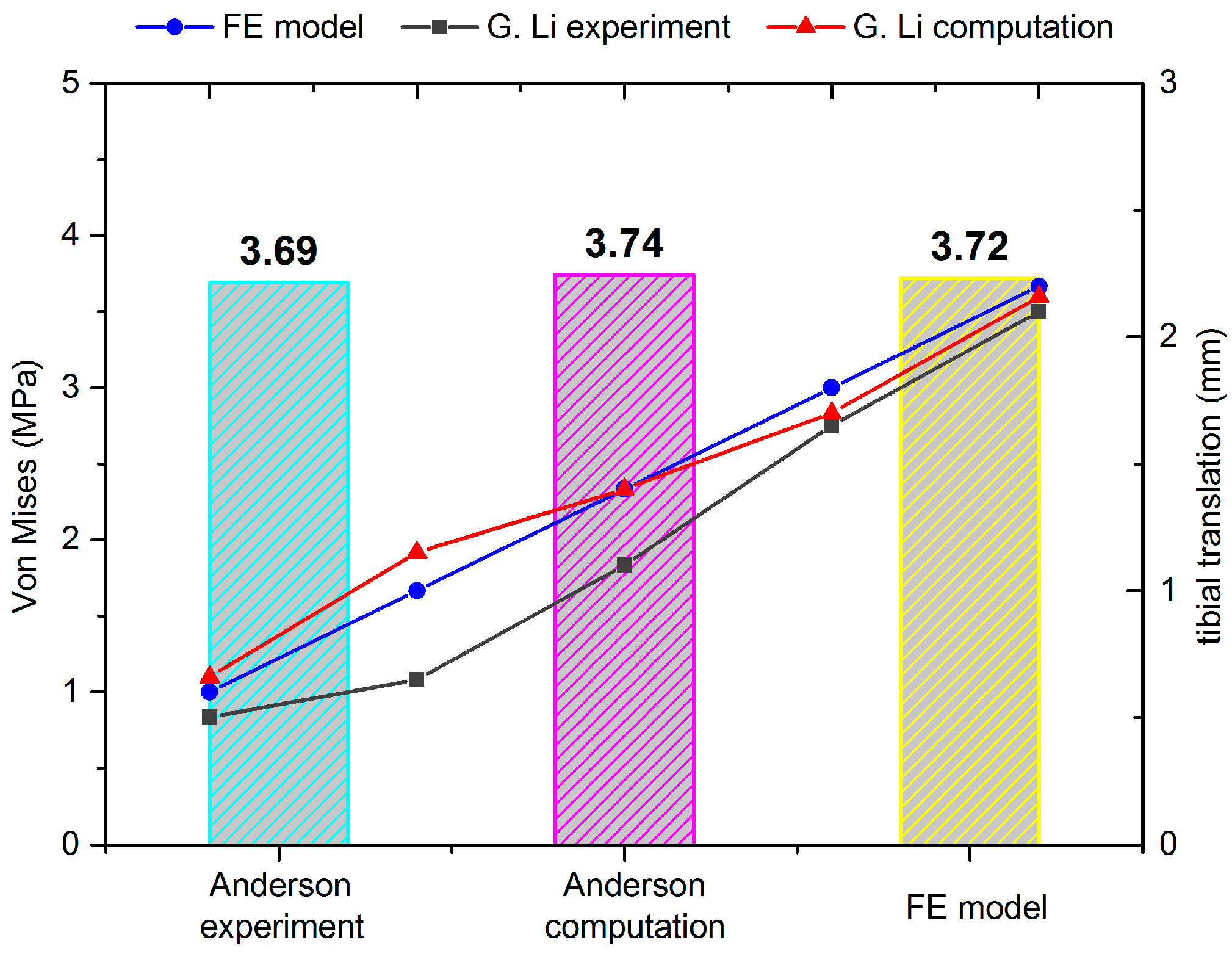
As shown in the histogram of Figure 2, the peak von Mises values of the inferior articular surface of the tibia were 3.69 MPa and 3.74 MPa in the results from Anderson [25], while it was 3.72 MPa in this study. The deviations were only 0.05% and 0.08%. Regarding anterior tibial translation, as shown in the line chart, the magnitudes in our study were 0.6 mm, 1.0 mm, 1.4 mm, 1.8 mm, and 2.2 mm, presenting a linear growth. It can be seen that our results were within or extremely close to the simulation and experimental results of [26].

3.2. Ankle Protection

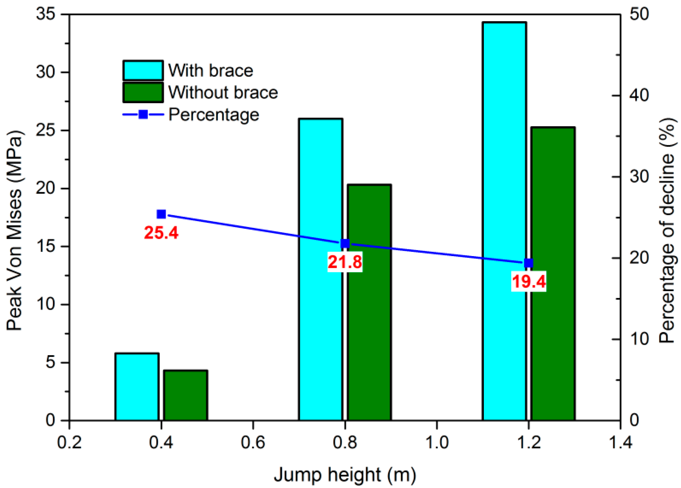
Figure 3 shows the peak von Mises stress of the inferior articular surface of tibia with and without the protective double-joint brace at 0.4 m, 0.8 m, and 1.2 m. Without the brace, the maximum von Mises stress increased from 5.787 MPa to 34.32 MPa when the jumping height increased from 0.4 m to 1.2 m, while it increased from 4.316 MPa to 25.27 MPa with the brace. Obviously, the stresses when wearing our brace were always lower than when not wearing it. After wearing the protective brace, the maximum stress on the inferior articular surface of tibia decreased by 25.4%, 21.8%, and 19.4%, respectively, at the heights of 0.4 m, 0.8 m, and 1.2 m.
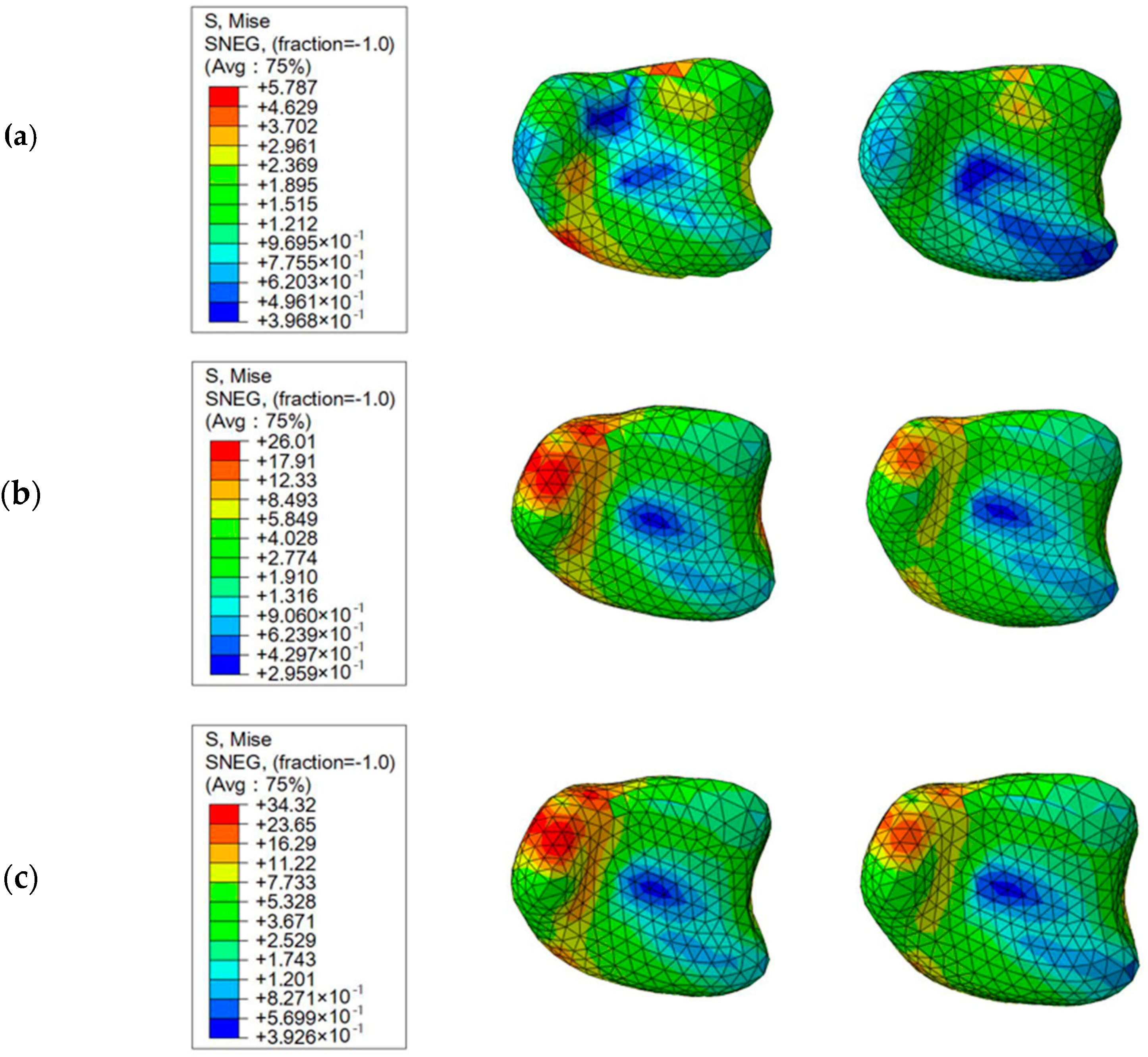
The stress distribution on the inferior articular surface of the tibia is presented in Figure 4. At the heights of 0.8 m and 1.2 m, stress concentrations were found to occur in similar locations, i.e., on the medial malleolus, while the stress on the posterior aspect of the articular surface was greater at 0.4 m. At the three heights, wearing the protective brace mainly reduced the stress peak at the stress concentration, but the pattern of stress distribution did not change obviously.
The average horizontal forces on the talus are shown in Table 1. Before wearing the brace, the average horizontal forces were 210.77 N, 270.91 N, and 347.45 N with increasing jump height. After wearing the brace, the average horizontal forces corresponding to the three heights decreased by 32%, 27.4%, and 27.5%, respectively, to 143.24 N, 196.82 N, and 251.87 N.

3.3. Knee Protection

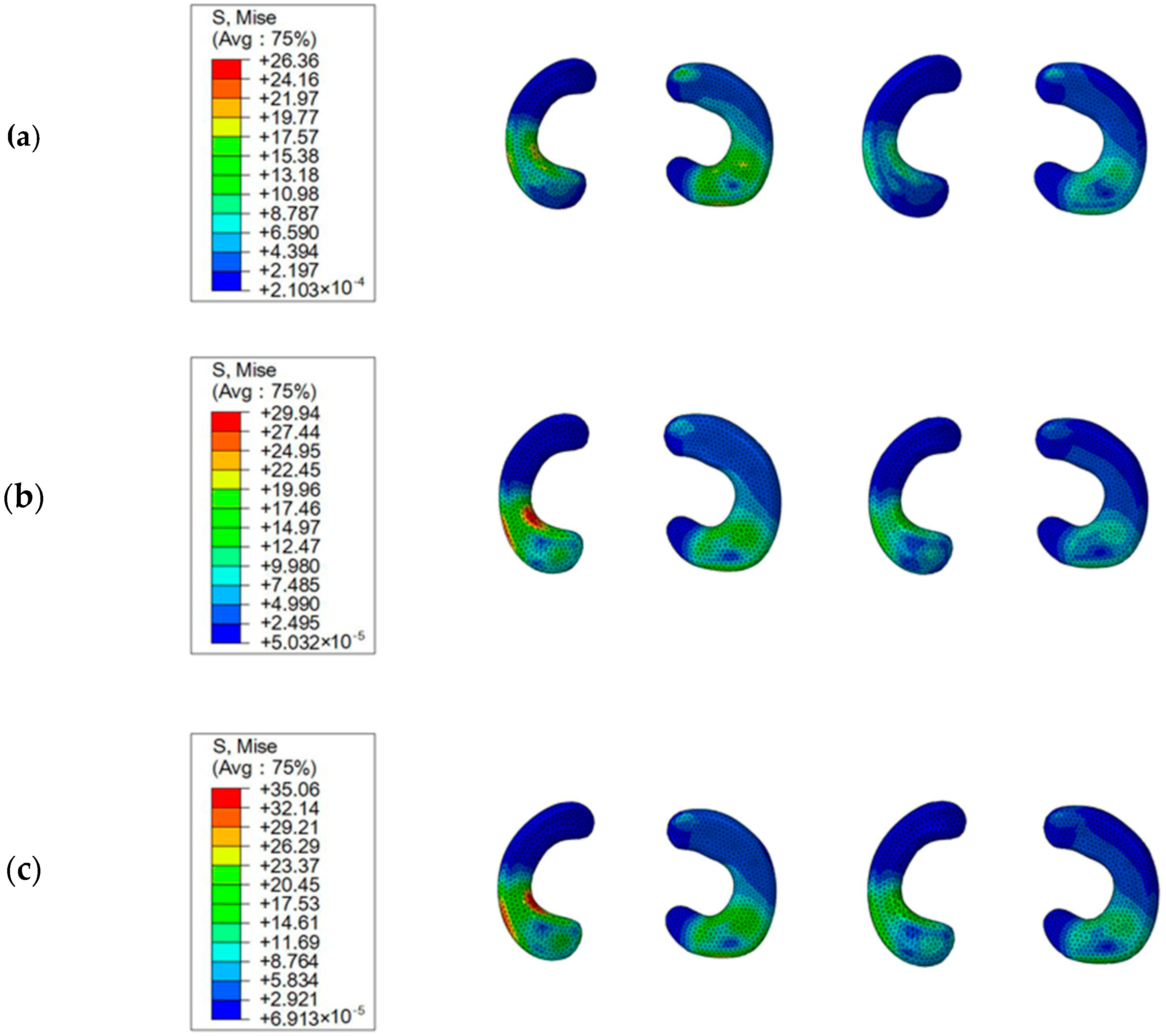
As can be seen from Table 2, no matter the height of the jump, the peak von Mises values of the menisci and articular cartilages decreased visibly after wearing the brace. With the brace, there were 23.8%, 21.5%, and 13.8% decreases in the peak von Mises stress of the menisci at the heights of 0.4 m, 0.8 m, and 1.2 m, respectively. As for the articular cartilages, the maximum von Mises stress decreased by 19.4%, 14.2%, and 9.1%, respectively. This serves to show that the peak von Mises values of the menisci were always higher than those of the articular cartilages at the three jumping heights with and without the brace.
Figure 5 shows the stress distribution on the menisci in braced and unbraced conditions at the three jumping heights. It can be seen that stress concentrations were found to occur in the medial meniscus without the brace. In contrast, stresses were more evenly distributed in the medial and lateral meniscus after wearing the brace.
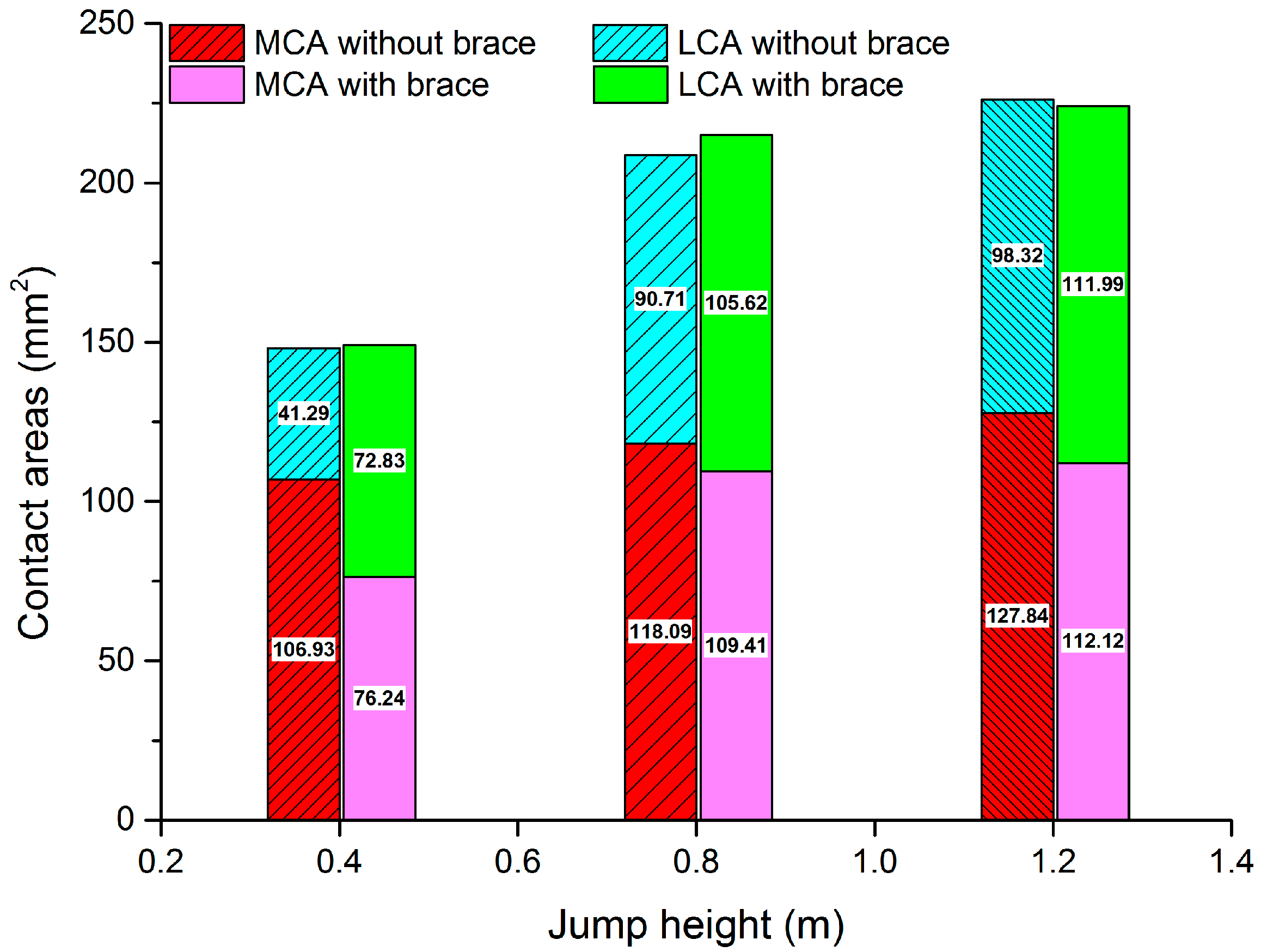
In order to further clarify the results, the contact areas of the menisci and articular cartilages were investigated, as shown in Figure 6. Although the total contact areas did not change obviously after wearing the brace, the medial contact area decreased and the lateral contact area increased, resulting in a more uniform distribution.

4. Discussion

During a half-squat landing, a GRF that is several times the BW is transmitted from the planta and ankle up to the shank and knee [5]. Furthermore, injuries that occur at the moment of landing are a direct result of excessive GRF [27,28]. Therefore, how to effectively reduce GRF has attracted the attention of scientists. In previous studies, the principle of protection for both knees and ankles focused on reducing the incidence of injury by limiting joint ROM [1,8,13,14,15]. Although such braces can provide beneficial protective effects, they also affect the user’s performance [16,17]. As a matter of course, a novel approach, which can not only counteract the action of the GRF, but also reduce the constraint on lower-limb movement, is essential for knee and ankle protection during landing. In this study, an FE model of the lower extremity was developed, and an anatomically detailed representation of the ankle and knee was constructed, with the reactions and tensions of soft tissue, ligamentous, and adjacent bony structures taken into consideration. Then, the biomechanical responses of the ankle and knee before and after wearing the brace were investigated and used to evaluate its protective performance.
The validation process was carried out in two steps, first for the ankle and then for the knee. The simulation was compared to previous experimental and computational results with similar settings to this study [25,26]. It can be seen that the deviations were only 0.05% and 0.08%, compared to Anderson’s results. As the difference was less than 1%, it was sufficient to validate the mechanical similarity of the ankle. Likewise, the results of anterior tibial translation, used to validate the mechanical similarity of the knee, were also consistent with the literature. It should be noted that our simulation results were higher than those of the cadaveric study. This difference may have been due to a decrease in system stiffness attributed to the simplification of ligaments and other soft tissues [29,30].
The tibia is the main weight-bearing bone of the shank, and the articular surface between the tibia and talus is the main load-bearing location of the ankle [7]. As can be seen from the results of Figure 3 and Figure 4, the peak von Mises stress of the inferior articular surface of the tibia increased visibly with increasing jump height. This is understandable, since the GRF is known to increase significantly with an increase in jump height [31], and the stress on the human body increases accordingly on the basis of the principle of inverse dynamics [32]. More importantly, when landing from a large height (0.8 m and 1.2 m), stress concentration occurred in vulnerable areas such as the medial condyle, which definitely increased the risk of compression fractures [33,34]. Comparatively, after wearing the brace, the stress peak decreased, thereby reducing the incidence of local fractures [35]. However, the pattern of stress distribution did not change, indicating that the semi-rigid brace at the ankle joint reduced stress by diverting some of the GRF that would otherwise be experienced by the human body, whereas it did not affect the way in which load was distributed over the impacted area. This portion of the transferred GRF was transmitted upward and gradually absorbed by the brace itself; in a practical device, hip components can also be added to help absorb impact energy.
In addition to stress fracture, ankle inversion and eversion represent common injuries that cannot be ignored [36]. Due to the special anatomical structure of the talus [37], which is wide in the anterior region and narrow in the posterior region, the foot is prone to varus and valgus when subjected to a high horizontal impact. Thus, the average horizontal force on the talus was calculated, and the results showed that, although the average horizontal force increased substantially as the jump height increased, wearing the brace could still evidently reduce the horizontal force at all three heights compared to not wearing the brace. We inferred the main reason as being also that the semi-rigid brace at the ankle joint transferred the GRF, resulting in a reduction in the force acting on the foot. With respect to ankle protection, our brace is in sharp contrast to prophylactic braces in previous studies [38,39,40]; that is, our brace reduces the risk of ankle injury by sharing and transferring the GRF with little effect on the joint ROM, which is attributed to the minor restriction exerted by the brace on the joint.
It is known that the knee is the second most frequent injury site during drop landing [6,41]. Landing injuries of knee include knee dislocation, cartilage fracture, ligament sprain, and meniscus damage, among which cartilage fracture and meniscus damage are considered to be serious injuries [42]. Therefore, in this study, we investigated the biomechanical responses of the articular cartilages and menisci, finding a rapid increase in stress peak with increasing jump height whether or not the brace was worn. However, the brace could reduce the risk of knee injury by reducing the peak von Mises stress of the menisci and articular cartilages at 0.4 m, 0.8 m, and 1.2 m. The reduction in knee internal stress was expected, because the presence of the ankle semi-rigid brace absorbed some of the GRF, thereby reducing the GRF acting on the lower limbs. A similar protective effect can be achieved with a functional knee brace, as found in [43], where the peak vGRFs were significantly reduced during drop jump landing. In contrast, our designed brace does not limit the ROM as much as a functional knee brace, which is more in line with the participant’s desired motion.
Furthermore, in the absence of our brace, the stress on the medial meniscus was apparently higher than that of the lateral meniscus, thus, rendering the medial meniscus more vulnerable to damage. This is in agreement with the opinion of [44] on human knee osteoarthritis, where the authors mentioned that 60% of load goes through the medial side of the knee during walking, and disease most often presents in the medial compartment of the joint. On the other hand, with the brace, the contact areas between the medial articular cartilage and meniscus decreased, while the lateral contact area increased, resulting in a more balanced load bearing of the medial and lateral meniscus. It is logical to argue that the retractive force attributed to an elongated spring component at the knee bending balanced the high impact experienced by the knee joint, converting some kinetic energy into elastic potential energy of the spring, thereby achieving a protective effect. This seems to be comparable to a previous study [45] on medial knee osteoarthritis rehabilitation, where the authors found that, with a laterally wedged insole (LWI), the von Mises stress at the medial femur cartilage region and the medial meniscus significantly decreased. Similarly, both an LWI and our brace can redistribute the knee internal loading and relieve the stress at the medial compartment of the knee.
In summary, this brace can be used as a parallel structure in the lower extremities with little constraint on the joint ROM, helping dissipate the GRF and reduce the force acting on the human body, in a similar way to cats having more limbs to cushion the impact [46]. There were some limitations in the context of model simplifications and settings. All bony tissues were assumed to be homogeneous, isotropic, and linear-elastic materials. Moreover, the ligaments were defined with tension-only truss elements, which may have resulted in stress concentration at the insertions. Another important limitation in the study was that the two ends of the brace were tied to the skin around the thigh and shank, whereas, in reality, the semi-rigid brace at the ankle joint was connected to the participant’s shoes, and the spring component at the knee joint was attached to the hip via rigid connecting rods.

5. Conclusions

Existing prophylactic knee and ankle braces, designed to reduce lower-limb injuries during landing due to the high GRF, work primarily by restraining the joint ROM; however, this protective approach is still controversial in consideration of the negative effects on joint function. The purpose of this study was, therefore, to provide a novel double-joint protection for the knee and ankle during landing and to evaluate its protective performance by using FE analysis.
Our results can be summarized as follows:
(1)
By absorbing some of the impact energy that would otherwise be experienced by the human body, the semi-rigid support at the ankle joint could reduce the peak stress on the inferior articular surface of the tibia and the horizontal force on the talus, thus, reducing the risk of ankle injury.
(2)
Additionally, the decreasing impact force on the lower extremity due to the semi-rigid support at the ankle joint could also reduce the stress peak of the menisci and articular cartilages in the knee joint.
(3)
Notably, as a function of the retractive force generated by the spring component at the knee joint, it could distribute the load in a better way such that the stress distribution and contact area between the menisci and articular cartilages were more equally distributed.
In contrast to previous work in this area, the brace we designed can provide double-joint protection for both knees and ankles, without limiting the ROM as much as prevailing braces. According to the protective principle of this brace, with the exception of those who suffered a musculoskeletal injury to the lower limbs, the target population can obviously be extended to anyone with impact resistance demands during jump landing, such as paratroopers and skydivers undertaking landing maneuvers. Future work could aim at improving comfort when wearing this brace.

Author Contributions

Conceptualization, B.P. and X.W.; methodology, X.W.; software, W.W.; validation, D.L., L.G. and P.H.; formal analysis, X.W.; investigation, X.W.; resources, X.W.; data curation, X.W.; writing—original draft preparation, X.W.; writing—review and editing, B.P.; visualization, B.P.; supervision, B.P.; project administration, B.P.; funding acquisition, B.P. All authors have read and agreed to the published version of the manuscript.

Funding

This research was funded by Defense Industrial Technology Development Program, grant number JCKY2018601B106.

Institutional Review Board Statement

The study was conducted according to the guidelines of the Declaration of Helsinki, and approved by the Ethics Committee of School of Biological Science and Medical Engineering in Beihang University (protocol code: BM201900125; date of approval: 10 February 2019).

Informed Consent Statement

An informed consent was obtained from the subject involved in the study.

Acknowledgments

We are indebted to Hao Liu and Daochen Wang for providing the helpful advice and consultation.

Conflicts of Interest

The authors declare no conflict of interest.

References

  1. Hanzlíková, I.; Richards, J.; Hébert-Losier, K.; Smékal, D. The effect of proprioceptive knee bracing on knee stability after anterior cruciate ligament reconstruction. Gait Posture 2019, 67, 242–247. [Google Scholar] [CrossRef]
  2. Bricknell, M.C.M.; Craig, S.C. Military parachuting injuries: A literature review. Occup. Med. 1999, 49, 17–26. [Google Scholar] [CrossRef] [PubMed] [Green Version]
  3. Yungchien, C.; Sell, T.C.; Abt, J.P.; Takashi, N.; Jennifer, D.; Mark, M.G.; Rusty, R.; Brian, S.; Lephart, S.M. Air assault soldiers demonstrate more dangerous landing biomechanics when visual input is removed. Mil. Med. 2012, 177, 41–47. [Google Scholar]
  4. Liebermann, D.G.; Hoffman, J.R. Timing of preparatory landing responses as a function of availability of optic flow in-formation. J. Electromyogr. Kinesiol. 2005, 15, 120–130. [Google Scholar] [CrossRef] [PubMed]
  5. Jiang, T.; Tian, S.; Fan, X.; Chen, T.; Luo, C.; Yao, J.; Wang, L. Kinematics and kinetics of lower-extremity joints in parachuting landing with backpack and knee brace. Med. Eng. Phys. 2020, 86, 1–7. [Google Scholar] [CrossRef]
  6. Ekeland, A. Injuries in military parachuting: A prospective study of 4499 jumps. Injury 1997, 28, 219–222. [Google Scholar] [CrossRef]
  7. Wong, D.W.-C.; Niu, W.; Wang, Y.; Zhang, M. Finite Element Analysis of Foot and Ankle Impact Injury: Risk Evaluation of Calcaneus and Talus Fracture. PLoS ONE 2016, 11, e0154435. [Google Scholar] [CrossRef] [PubMed] [Green Version]
  8. Wu, D.; Zheng, C.; Wu, J.; Wang, L.; Wei, X.; Wang, L. Protective Knee Braces and the Biomechanics of the Half-Squat Parachute Landing. Aerosp. Med. Hum. Perform. 2018, 89, 26–31. [Google Scholar] [CrossRef] [PubMed]
  9. Herscovici, D.; Scaduto, J.M. Management of High-Energy Foot and Ankle Injuries in the Geriatric Population. Geriatr. Orthop. Surg. Rehabil. 2012, 3, 33–44. [Google Scholar] [CrossRef] [PubMed]
  10. Ihmels, W.D.; Seymore, K.D.; Brown, T.N. Effect of Sex and Ankle Brace Design on Knee Biomechanics During a Single-Leg Cut. Am. J. Sports Med. 2020, 48, 1496–1504. [Google Scholar] [CrossRef]
  11. Hangalur, G.; Brenneman, E.; Nicholls, M.; Bakker, R.; Laing, A.; Chandrashekar, N. Can a knee brace reduce the strain in the anterior cruciate ligament? A study using combined in vivo/in vitro method. Prosthetics Orthot. Int. 2016, 40, 394–399. [Google Scholar] [CrossRef]
  12. Sinclair, J.K.; Selfe, J.; Taylor, P.J.; Shore, H.F.; Richards, J.D. Influence of a knee brace intervention on perceived pain and patellofemoral loading in recreational athletes. Clin. Biomech. 2016, 37, 7–12. [Google Scholar] [CrossRef] [Green Version]
  13. Hanzlíková, I.; Richards, J.; Tomsa, M.; Chohan, A.; May, K.; Smékal, D.; Selfe, J. The effect of proprioceptive knee bracing on knee stability during three different sport related movement tasks in healthy subjects and the implications to the man-agement of Anterior Cruciate Ligament (ACL) injuries. Gait Posture 2016, 48, 165–170. [Google Scholar] [CrossRef]
  14. Gudibanda, A.; Wang, Y. Effect of the Ankle Stabilizing Orthosis on Foot and Ankle Kinematics During Cutting Maneuvers. Res. Sports Med. 2005, 13, 111–126. [Google Scholar] [CrossRef]
  15. Stoffel, K.K.; Nicholls, R.L.; Winata, A.R.; Dempsey, A.R.; Boyle, J.J.W.; Lloyd, D.G. Effect of Ankle Taping on Knee and Ankle Joint Biomechanics in Sporting Tasks. Med. Sci. Sports Exerc. 2010, 42, 2089–2097. [Google Scholar] [CrossRef] [Green Version]
  16. Zhang, S.; Wortley, M.; Chen, Q.; Freedman, J. Efficacy of an Ankle Brace with a Subtalar Locking System in Inversion Control in Dynamic Movements. J. Orthop. Sports Phys. Ther. 2009, 39, 875–883. [Google Scholar] [CrossRef] [Green Version]
  17. Bot, S.D.M.; Mechelen, W.V. The Effect of Ankle Bracing on Athletic Performance. Sports Med. 1999, 27, 171–178. [Google Scholar] [CrossRef] [Green Version]
  18. Mason-Mackay, A.R.; Whatman, C.; Reid, D.; Lorimer, A. The effect of ankle bracing on landing biomechanics in female netballers. Phys. Ther. Sport 2016, 20, 13–18. [Google Scholar] [CrossRef]
  19. Wu, X.; Pei, B.; Pei, Y.; Hao, Y.; Zhou, K.; Wang, W. Comprehensive Biomechanism of Impact Resistance in the Cat’s Paw Pad. BioMed Res. Int. 2019, 2019, 31467873. [Google Scholar] [CrossRef] [PubMed] [Green Version]
  20. Wu, X.; Pei, B.; Pei, Y.; Wang, W.; Hao, Y.; Zhou, K. How do Cats Resist Landing Injury: Insights into the Multi-level Buffering Mechanism. J. Bionic Eng. 2020, 17, 600–610. [Google Scholar] [CrossRef]
  21. Athanasiou, K.A.; Liu, G.T.; Lavery, L.A.; Lanctot, D.R.; Schenck, R.C. Biomechanical Topography of Human Articular Cartilage in the First Metatarsophalangeal Joint. Clin. Orthop. Relat. Res. 1998, 348, 269–281. [Google Scholar] [CrossRef]
  22. Siegler, S.; Block, J.; Schneck, C.D. The Mechanical Characteristics of the Collateral Ligaments of the Human Ankle Joint. Foot Ankle 1988, 8, 234–242. [Google Scholar] [CrossRef] [PubMed]
  23. Wang, Y.; Li, Z.; Wong, W.C.; Cheng, C.K.; Zhang, M. Finite element analysis of biomechanical effects of total ankle ar-throplasty on the foot. J. Orthop. Transl. 2018, 12, 55–65. [Google Scholar]
  24. Cheung, T.M.; Zhang, M.; Leung, K.L.; Fan, Y.B. Three-dimensional finite element analysis of the foot during standing—A material sensitivity study. J. Biomech. 2005, 38, 1045–1054. [Google Scholar] [CrossRef] [PubMed]
  25. Anderson, D.D.; Goldsworthy, J.K.; Li, W.; Rudert, M.J.; Tochigi, Y.; Brown, T.D. Physical validation of a patient-specific contact finite element model of the ankle. J. Biomech. 2007, 40, 1662–1669. [Google Scholar] [CrossRef] [PubMed] [Green Version]
  26. Li, G.; Gil, J.; Kanamori, A.; Woo, S.L.-Y. A Validated Three-Dimensional Computational Model of a Human Knee Joint. J. Biomech. Eng. 1999, 121, 657–662. [Google Scholar] [CrossRef]
  27. Li, Y.; Wu, J.; Zheng, C.; Huang, R.R.; Na, Y.; Yang, F.; Wang, Z.; Wu, D. The Effect of Landing Surface on the Plantar Kinetics of Chinese Paratroopers Using Half-Squat Landing. J. Sports Sci. Med. 2013, 12, 409–413. [Google Scholar]
  28. Huang, H.-Y.; Teng, T.-L.; Liang, C.-C. Lower Extremity Injuries of Volleyball Players During Moving Spike Landing. Am. J. Sports Sci. 2016, 4, 10. [Google Scholar] [CrossRef] [Green Version]
  29. Song, Y.; Debski, R.E.; Musahl, V.; Maribeth, T.; Woo, S.L.-Y. A three-dimensional finite element model of the human anterior cruciate ligament: A computational analysis with experimental validation—ScienceDirect. J. Biomech. 2004, 37, 383–390. [Google Scholar] [CrossRef]
  30. Li, G.; Suggs, J.; Gill, T. The Effect of Anterior Cruciate Ligament Injury on Knee Joint Function under a Simulated Muscle Load: A Three-Dimensional Computational Simulation. Ann. Biomed. Eng. 2002, 30, 713–720. [Google Scholar] [CrossRef]
  31. Niu, W.; Feng, T.; Jiang, C.; Zhang, M. Peak vertical ground reaction force during two-leg landing: A systematic review and mathematical modeling. BioMed Res. Int. 2014, 2014, 126860. [Google Scholar] [CrossRef] [PubMed]
  32. Winter, D.A. Biomechanics and Motor Control of Human Movement, 4th ed.; Wiley: Hoboken, NJ, USA, 2009. [Google Scholar]
  33. Forman, J.L.; Lopez-Valdes, F.J.; Duprey, S.; Bose, D.; de Dios, E.d.P.; Subit, D.; Gillispie, T.; Crandall, J.R.; Segui-Gomez, M. The tolerance of the human body to automobile collision impact—A systematic review of injury biomechanics research, 1990–2009. Accid. Anal. Prev. 2015, 80, 7–17. [Google Scholar] [CrossRef] [PubMed]
  34. Funk, J.R.; Crandall, J.R.; Tourret, L.J.; MacMahon, C.B.; Bass, C.R.; Patrie, J.T.; Khaewpong, N.; Eppinger, R.H. The Axial Injury Tolerance of the Human Foot/Ankle Complex and the Effect of Achilles Tension. J. Biomech. Eng. 2002, 124, 750–757. [Google Scholar] [CrossRef]
  35. Nalla, R.K.; Stölken, J.; Kinney, J.H.; Ritchie, R.O. Fracture in human cortical bone: Local fracture criteria and toughening mechanisms. J. Biomech. 2005, 38, 1517–1525. [Google Scholar] [CrossRef]
  36. Refshauge, K.M.; Raymond, J.; Kilbreath, S.L.; Pengel, L.; Heijnen, I. The Effect of Ankle Taping on Detection of Inversion-Eversion Movements in Participants with Recurrent Ankle Sprain. Am. J. Sports Med. 2009, 37, 371–375. [Google Scholar] [CrossRef] [PubMed]
  37. Johnson, K.A. Anatomy of the Foot and Ankle: Descriptive, Topographic, Functional. Mayo Clin. Proc. 1984, 59, 289. [Google Scholar] [CrossRef]
  38. Knapik, J.J.; Spiess, A.; Swedler, D.I.; Grier, T.L.; Darakjy, S.S.; Jones, B.H. Systematic Review of the Parachute Ankle Brace. Am. J. Prev. Med. 2010, 38, S182–S188. [Google Scholar] [CrossRef]
  39. Wu, D.; Zheng, C.; Wu, J.; Hu, T.; Huang, R.; Wang, L.; Fan, Y. Prophylactic Ankle Braces and the Kinematics and Kinetics of Half-Squat Parachute Landing. Aerosp. Med. Hum. Perform. 2018, 89, 141–146. [Google Scholar] [CrossRef]
  40. Niu, W.; Wang, Y.; He, Y.; Fan, Y.; Zhao, Q. Biomechanical Gender Differences of the Ankle Joint During Simulated Half-Squat Parachute Landing. Aviat. Space Environ. Med. 2010, 81, 761–767. [Google Scholar] [CrossRef]
  41. Amoroso, P.J.; Bell, N.S.; Jones, B.H. Injury among female and male army parachutists. Aviat. Space Environ. Med. 1997, 68, 1006–1011. [Google Scholar]
  42. Amamilo, S.C.; Samuel, A.W.; Hesketh, K.T.; Moynihan, F.J. A prospective study of parachute in-juries in civilians. J. Bone Jt. Surg. 1987, 69, 17–19. [Google Scholar] [CrossRef]
  43. Rishiraj, N.; Taunton, J.E.; Lloyd-Smith, R.; Regan, W.; Niven, B.; Woollard, R. Functional knee brace use effect on peak vertical ground reaction forces during drop jump landing. Knee Surg. Sports Traumatol. Arthrosc. 2012, 20, 2405–2412. [Google Scholar] [CrossRef]
  44. Jones, R.K.; Chapman, G.J.; Findlow, A.H.; Forsythe, L.; Parkes, M.J.; Sultan, J.; Felson, D.T. A New Approach to Prevention of Knee Osteoarthritis: Reducing Medial Load in the Contralateral Knee. J. Rheumatol. 2013, 40, 309–315. [Google Scholar] [CrossRef] [Green Version]
  45. Liu, X.; Zhang, M. Redistribution of knee stress using laterally wedged insole intervention: Finite element analysis of knee–ankle–foot complex. Clin. Biomech. 2013, 28, 61–67. [Google Scholar] [CrossRef]
  46. Wu, X.; Pei, B.; Pei, Y.; Wu, N.; Zhou, K.; Hao, Y.; Wang, W. Contributions of Limb Joints to Energy Absorption during Landing in Cats. Appl. Bionics Biomech. 2019, 2019, 3815612–3815613. [Google Scholar] [CrossRef]
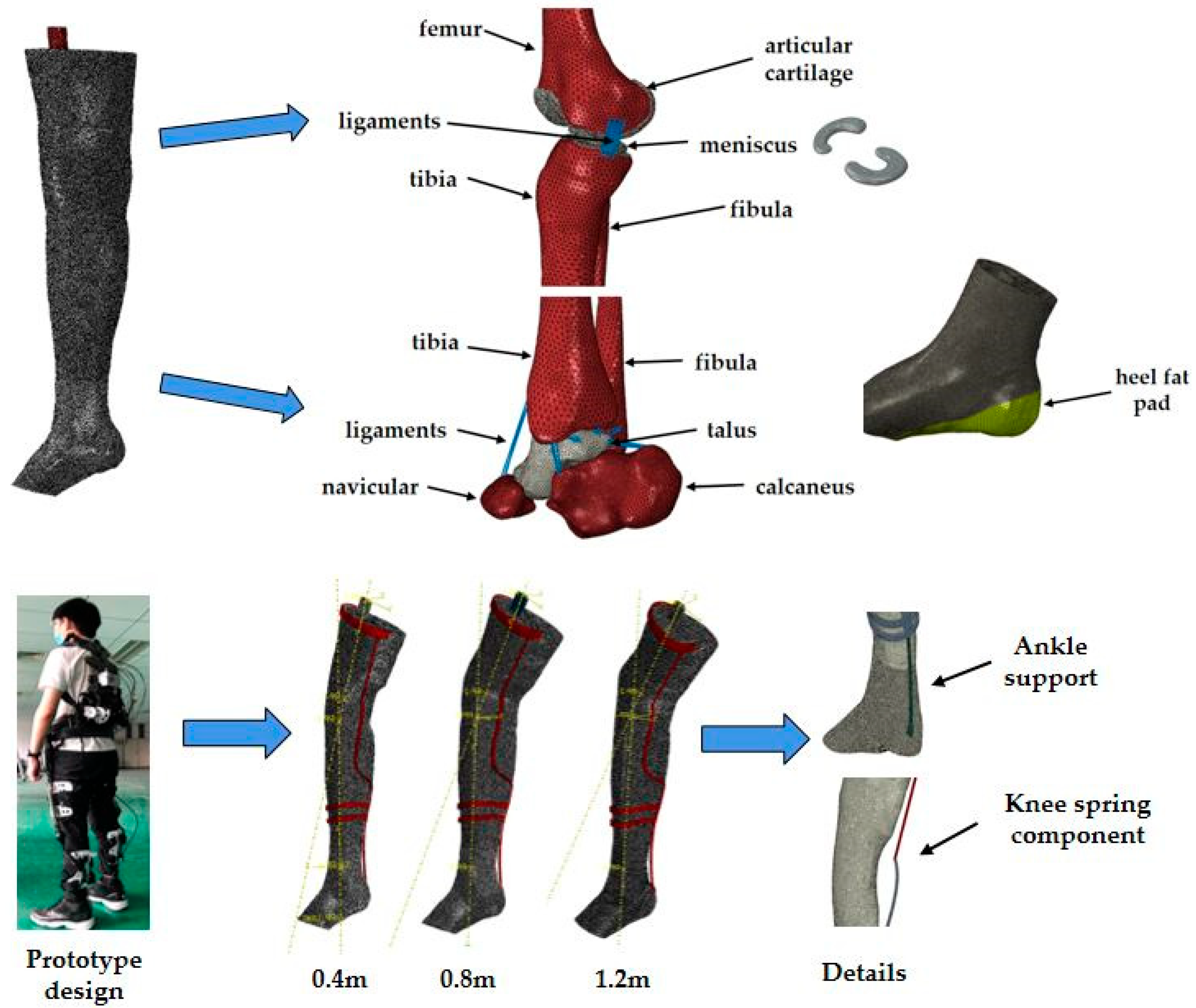
Figure 1. Finite element model of the ankle and knee complex, showing a detailed view of the segments and demonstrating the braced conditions used in the simulation.
Applsci 11 01912 g001
Figure 2. Validation of finite element model via comparison to existing studies. The bottom axis, left axis, and histogram show the comparison with Anderson’s results to validate the biomechanical property of the ankle, while the top axis, right axis, and line chart present the comparison with Li’s results to validate the biomechanical property of the knee.
Applsci 11 01912 g002
Figure 3. Maximum von Mises stress of the inferior articular surface of the tibia with and without the brace, and the percentage decline in peak value at the three different heights.
Applsci 11 01912 g003
Figure 4. Von Mises stress distribution of the inferior articular surface of the tibia in braced (right) and unbraced (left) conditions at (a) 0.4 m, (b) 0.8 m, and (c) 1.2 m.
Applsci 11 01912 g004
Figure 5. Von Mises stress distribution of the menisci in braced (right) and unbraced (left) conditions at (a) 0.4 m, (b) 0.8 m, and (c) 1.2 m.
Applsci 11 01912 g005
Figure 6. The medial contact area (MCA) and lateral contact area (LCA) between the menisci and articular cartilages before and after wearing the brace.
Applsci 11 01912 g006
Table 1. The average horizontal forces on the talus with and without the brace at 0.4 m, 0.8 m, and 1.2 m.
Height (m)Horizontal Force with Brace (N)Horizontal Force without Brace (N)Percentage Decline
0.4210.77143.2432%
0.8270.91196.8227.4%
1.2347.45251.8727.5%
Table 2. The peak von Mises stress of the menisci and articular cartilages with and without the brace at 0.4 m, 0.8 m, and 1.2 m.
Height (m)Part InstancesPeak Von Mises Stress with Brace (MPa)Peak Von Mises Stress without Brace (MPa)Percentage Decline
0.4Menisci26.3620.0823.8%
Articular cartilages6.0184.8519.4%
0.8Menisci29.9423.5121.5%
Articular cartilages17.4114.9414.2%
1.2Menisci35.0630.2213.8%
Articular cartilages21.0719.159.1%
Publisher’s Note: MDPI stays neutral with regard to jurisdictional claims in published maps and institutional affiliations.