Article

Performance Evaluation of Rigid Braced Indirect Suspended Ceiling with Steel Panels

Department of Architectural Engineering, Ajou University, Suwon 16499, Korea
*
Author to whom correspondence should be addressed.
Appl. Sci. 2021, 11(5), 1986; https://doi.org/10.3390/app11051986
Submission received: 11 January 2021 / Revised: 19 February 2021 / Accepted: 22 February 2021 / Published: 24 February 2021

Abstract

:
In Korea, the earthquakes in Gyeongju (2016) and Pohang (2017) have led to increased interest in the seismic design of nonstructural elements. Among these, the suspended ceiling can cause personal injury and property damage. In addition, most suspended ceilings that are used in Korea neither have seismic design details nor meet the current seismic design standards. There are two seismic design methods for suspended ceilings using a perimeter clip and a brace. In the United States and Japan, seismic design of ceilings is typically used, but the concepts of applying and installing braces are different. This is because the typical ceiling systems are different in the United States and Japan. In this study, a brace-applied ceiling system that is suitable for a suspended ceiling with a steel panel was applied in the indirect suspended ceiling mainly used in Korea. In addition, the seismic performance was verified through a shaking table test. All the specimens were applied with anti-falling clips that are designed to prevent the panels from falling, and they satisfy KDS 41 17 00, which is a Korean seismic design life safety standard. Without considering these factors, the performance level is lower than a nonseismic designed ceiling, which is not properly designed or constructed.

1. Introduction

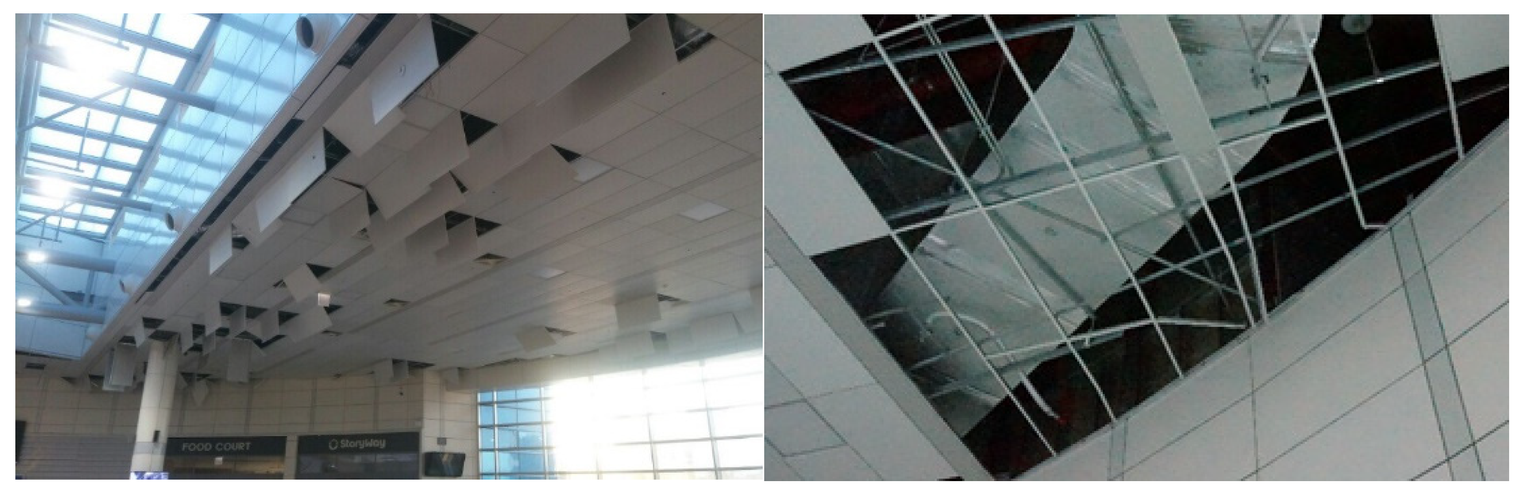
In Korea, the Gyeongju earthquake of 2016 and the Pohang earthquake of 2017 resulted in substantial damage to nonstructural elements such as exterior walls, suspended ceilings, and partition walls. As a result, the interest in seismic design of nonstructural elements has recently increased. Even if a building does not collapse owing to the damage to structural materials in the event of an earthquake, damage to the nonstructural elements may lead to casualties or property damage. When considering the nonstructural elements, the suspended ceiling system can directly lead to casualties inside the building because of failure of finishing or collapse of the ceiling frame. This can lead to additional damage, such as by blocking evacuation paths and damaging the various facilities. Figure 1 shows a suspended ceiling with steel panel damage at Pohang Station during the Pohang earthquake.
The KDS 41 17 00 [1] is a Korean building seismic design standard that was revised in early 2019. This standard mandates the use of ceiling bracing systems if a ceiling system with non-adhesive panels belongs to the seismic design category D, has certified perimeter clips, or the ceiling area exceeds 250 m2. This is the same as the ASCE7 in the United States, which includes two seismic designs on the ceiling. If the perimeter clips are used, walls are needed to hold the clips, and if the brace is used, brace members and other members to connect them are needed. A ceiling system with non-adhesive ceiling panels is different from one with attached ceiling panels. A ceiling system with attached ceiling panels is placed in or is inserted into the grid member, which is fixed with screws or nails to the ceiling grid. The KDS 41 17 00 ceiling standards in are similar to those in the ASCE7-16 [2]; however, the details of seismic design category (SDC) C are not provided, and the ceiling area to which the ceiling bracing system is applied to has been eased. The ASTM E580/E580M [3] in the United States requires braces at intervals of 1.8–3.6 m for ceiling installation areas not less than 1000 ft2. In particular, when considering rigid braces, the relative displacement is less than 6 mm. The details of the gap between the sprinklers are specified, but there is no information on the end separation distance when installing the brace. For spacing with sprinklers, it is deemed that the end separation distance should not be less than 25 mm, and the end molding must have a width of at least 50 mm. In the United States and Japan, seismic designs of ceilings are typically used, but the concepts of applying and installing braces are different. This is because the typical ceiling systems are different in the United States and Japan.
In 2013, the report in Japan, “Determining a Safe Structural Method for Specific Ceilings and Specific Ceiling Structural Strengths” Notice No. 771, was published by the Ministry of Land, Infrastructure, Transport and Tourism (MLIT). According to this report, when the ceiling installation area is more than 200 m2, the brace should be placed in the shape of a V by calculating the required brace number, with the end clearance being at least 60 mm. The V shape indicates a rigid brace; the width of the molding is not given.
As specified in the recommendations for seismic design and construction of nonstructural elements [4] from the Architectural Institute of Japan (AIJ), one V brace member should be within 30 m2 in each direction. This is determined to be a regulatory design method through experimentation, but the installation spacing of the brace and end clearance are not specified; thus, it is considered to be difficult to apply in practice.
Table 1 provides a brief summary of the contents of the ceiling system that are related to the brace installation in KDS 41 17 00, ASCE7-16, and MLIT Notice No. 771. The installation of a ceiling system with non-adhesive ceiling panels that is presented in ASCE7-16 is described in detail in ASTM E580/E580M.
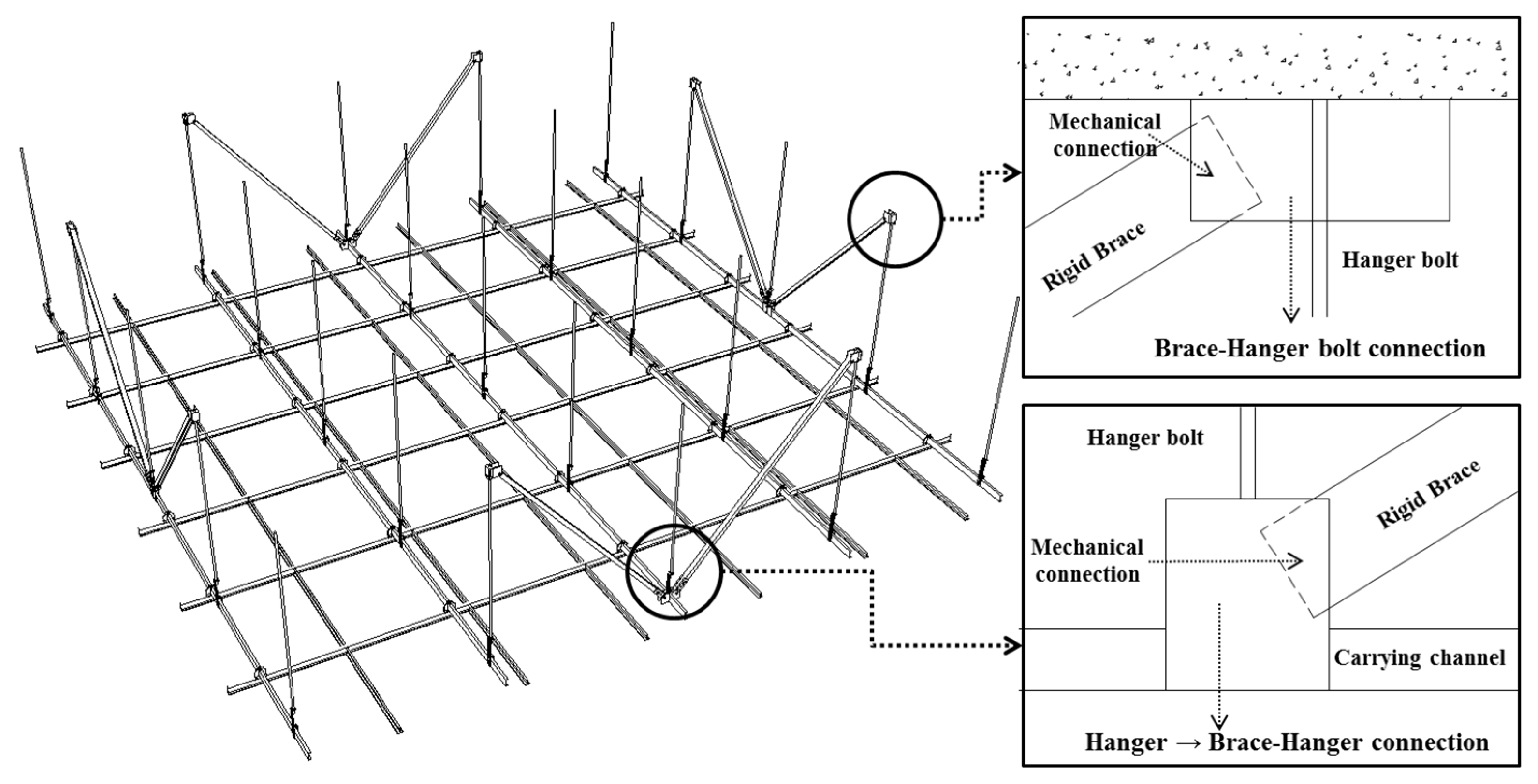
As shown in Figure 2, the brace system has a strut–tie system that uses wires and a rigid brace with high-rigidity members. In the ASTM E580/E580M, both the strut–tie brace and rigid brace that are shown in Figure 2 are presented. In Figure 2a, the hanging member and brace are mainly constructed to respond to the tensile forces by using wires and to take charge of the compression force by using vertical struts. In Figure 2b, when considering a suspended member, the load in the gravitational direction of the ceiling is in charge, and the brace is responsible for the tensile and compressive forces.
In countries that use direct suspended ceilings, such as the United States, most braces use wires. Meanwhile, for Japan, which mostly uses indirect suspended ceilings, rigid braces are often used. However, for all brace systems overseas, the end clearance and separation distances of the braces for the installation are not provided in detail. Research cases for ceiling systems that apply braces are also extremely rare. In addition, the exact construction methods, such as the above standards and specifications, have not been presented. The representative studies of the ceiling systems that apply braces are described as follows.
Gilani et al. [5] analyzed the existing earthquake damage cases and the criteria that are applied to the ceiling, and compared them to prior case studies. In addition, a shaking table experiment was performed according to the brace installation method that was suggested by the Ceilings & Interior Systems Construction Association (CISCA) and ASCE7, and a fragility curve was prepared. From the experimental results, it was confirmed that the acceleration was amplified more than the acceleration in the vertical direction that was suggested by the standard. It was also confirmed that it is different from the damage pattern for earthquake damage.
Brandolese et al. [6] analyzed a ceiling system in which a brace was applied in a quasi-static experiment through repeated loading. For different vibration periods depending on the ceiling installation height, the elastic displacement and acceleration that used the displacement base were evaluated. A brace system and its accessories were introduced, and these can be directly applied to the suspension.
Ozcelik et al. [7] studied steel-panel suspended ceilings, conducting tests with steel and gypsum panels while varying the application of perimeter clips and the thickness of the suspension wires. The results of their tests showed the definition of the performance level of the ceiling system.
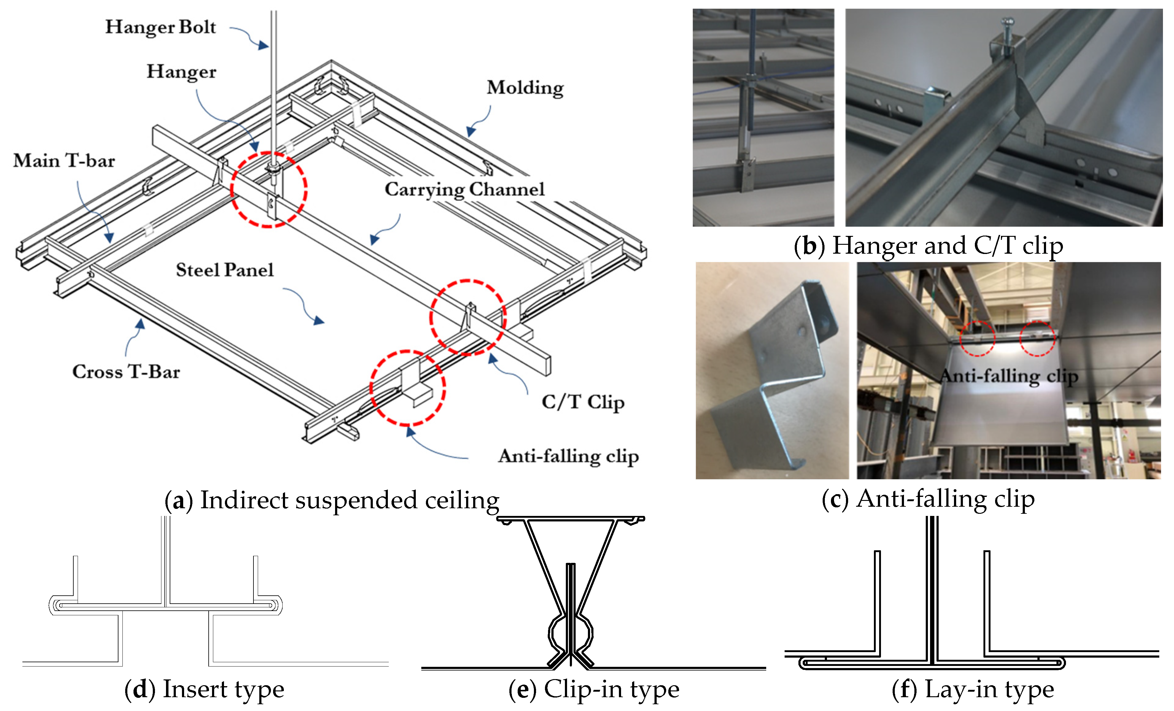
These research cases that were previously described are similar to the T-bar products in Korea; however, most of them use direct suspended ceilings and, as shown in Figure 3a, the method of installing finishing materials is different. As a result, it is difficult to apply them in practice. In addition, there is a paucity of studies on ceiling systems with braces. Similarly, studies on the actual application method and behavior of the rigid brace as suggested in the standards are also scant.
In this study, a shaking table test was performed. This was achieved by applying a brace to a ceiling system of steel panels of which the indirect suspended ceiling is mainly used in Korea. The test specimens were subjected to different end clearances, joints, and brace installation intervals. These specimens were analyzed and compared to the experimental results from a previous study [8], which describes the non-seismic ceiling system. The basis for this study is the KDS 41 17 00 in Korea, which is similar to ASCE7-16 in the United States. In addition, a rigid brace-based seismic ceiling system that is suitable for the Korean situation is proposed, and its performance is evaluated by performing a shaking table test. As shown in Figure 3c, the specimens used in this study had an anti-falling clip similar to the previous study, that is, a device was installed to prevent the panel from completely dropping out.

2. Experimental Program

2.1. Design of Test Specimens

As shown in Figure 3a, most of the ceiling systems that are applied in Korea use indirect suspended ceilings are composed of hanger bolts, carrying channels, a main T-bar, and a cross T-bar. The connections between the members are a hanger, carrying channel/T-bar clip (C/T clip), and a connection in the grid between the T-bars. The hanger connects the hanger bolt and the carrying channel, and the C/T clip connects the carrying channel and the T-bar.
The panels that are used in the T-bar system are mostly ceiling systems with nonadhesive ceiling panels and can be classified into three types, as shown in Figure 3d–f. All three types can be classified as non-adhesive ceiling panels. Figure 3f is the most widely used lay-in type, which is mounted on a T-shaped grid member for construction. As depicted in Figure 3e, this is a clip-in type, and it is constructed by inserting a panel into a member, forming a grid. The members forming the grid that used the clip-in type were manufactured so that the panels could be inserted. Figure 3d shows the type of steel panels that were used in this study. The panel is inserted into the T-shaped grid member, and the panel is manufactured so it can be fitted into the grid member. In Korea, ceiling systems with steel panels are mainly used in large spaces with high floors and large ceiling areas. In addition, they are developed with a focus on the ease of maintenance and construction. If these steel panels fall during an earthquake, personal injuries may occur because of the high floor height and panel weight.
Figure 4 shows the concept of the brace system that was used in this study. In order to apply the brace in two directions for an indirect suspended ceiling, it should be applied using a hanger bolt, a carrying channel, and a hanger to form the connection. This study applied the existing research and products to the direct suspended ceiling and they are not consistent with the situation in Korea. It was newly developed for an indirect suspended ceiling.
The shaking table test consisted of two specimens, and it was performed with variables such as the end clearance, molding width, and brace spacing on the steel frames with a ceiling installation area of 3.8 m × 3.8 m. According to the MLIT Notice No. 771, the seismic designed ceiling applying brace (2 units) (SDB-2) specimen was applied with an end clearance distance of 60 mm and a molding width of 90 mm. In addition, mechanical jointing was performed on the C/T clip and the hanger. For the seismic designed ceiling applying brace (3 units) (SDB-3) specimen, a molding width of 50 mm and an end clearance distance of 25 mm were used. Mechanical jointing was performed for the C/T clips and hangers, and a specially designed main T-bar–cross T-bar connection was used to perform mechanical jointing. The un-seismic designed ceiling (USD) is a test specimen that has not been subjected to a seismic design that applies the details of a steel panel in Korea. It does not have mechanical joints and is characterized by a narrow molding width for aesthetic reasons. The USD was analyzed in a previous study [8] that was used as a comparative specimen for the experiment in this study. Table 2 lists the variables that were checked for each test subject.
In the case of the brace and hanger bolt connector, which was used in SDB-2, it is joined to the brace with bolts, but it can easily yield because of its long and thin shape. The connector that was used in SDB-3 was developed by supplementing this easily yielding shape and it was joined to the brace by using screw bolts.
The two ceiling systems that applied a brace and the nonseismic ceiling system were subjected to a comparative experiment. The main T-bar and the cross T-bar constituting the ceiling grid were installed at 600 mm intervals as shown in Figure 5a, and a 600 mm × 600 mm steel panel was installed with an anti-falling clip between the main T-bar and steel panel.
The braces of the test specimens were installed as shown in Figure 6. All of the members that were used in this test consisted of components presented in KS D 3609 [9], which is the Korean ceiling system product standard. The hanger bolts were installed at 900 mm intervals, the same as the installation interval for the carrying channel.
As shown in Figure 6b, a brace reinforcement member was installed in order to disperse the carrying channel as the carrying channel would receive an excessive load at the part where it was connected to the brace. The brace reinforcement member was installed between the carrying channels as shown in Figure 7 to distribute the load.

2.2. Test Setup and Test Protocol

The steel frame for the test on which the ceiling system was installed was 4 m wide and 4 m long, and its primary natural frequency (fn), as estimated through the structural analysis program, Midas gen, was 25 Hz in the x-direction and 32 Hz in the y-direction.
ICC-ES AC156 [10], which is the test standard for nonstructural elements, suggests that the experimental frame should have adequate rigidity to avoid resonance with the nonstructural elements and to transmit the floor vibrations to nonstructural elements. The results of the shaking table test confirmed that the steel frame transmitted floor vibrations to the ceiling material. Figure 8 shows the steel frame that was used in the shaking table test.
For the specimen that the brace was applied to, an accelerometer was installed, as shown in Figure 9, to measure the response of the specimen during an earthquake. For this investigation, 11 accelerometers were installed in each direction: one at the center of the shaking table surface, five at the top of the test frame, and five on the ceiling surface.
Four displacement meters were installed so that the displacement of the ceiling and test frame could be measured with respect to the two-way axis. The plan with the vibration band was established in accordance with ICC-ES AC156. Artificial seismic waves were first generated on the x-axis for two-way retention, and artificial seismic waves on the y-axis were redesigned to avoid the x-direction and resonance. In accordance with KDS 41 17 00, the short-period design spectral response acceleration (SDS) was 0.54 g (seismic zone Ⅱ, ground condition), and the height z of the nonstructural element installation was assumed to be the same as h. AFLX-H was calculated as 0.864 g and ARIG-H was determined to be 0.648 g according to the equation below. From this, EQ100% was formed, and the acceleration level of the artificial seismic wave increased in stages, which confirms the damage status of the ceiling system.
AFLX-H = SDS (1 + 2 z/h) = 0.54 g × (1 + 2) = 1.62 g < AFLX-H,Max = 1.6SDS = 0.864 g
AFLX-H = 0.864 g
ARIG-H = 0.4SDS (1 + 2 z/h) = 0.4 × 0.54 g × (1 + 2) = 0.648 g
Table 3 lists the artificial seismic wave levels applied in the test, and Figure 10 shows the test response spectrum (TRS) in Test 2 (0.864 g) that was measured on the shaking table surface (A1) for the SDB-2 specimen.
Figure 10 shows the test response spectrum (TRS) and the required response spectrum (RRS) for each direction of the shaking table surface (A1). The TRS is located in the RRS of 90% or more and 130% or less on the graph. This means that the artificial seismic wave was designed to satisfy the AC156 standard, and the experiment was conducted. The TRS refers to the acceleration response spectrum of the time history data that were measured by an accelerometer attached to the surface of the shaking table.

3. Test results

3.1. Failure Mode and Damage State for the Specimens

On the basis of the findings by Gilani et al. [11], the damage stages of the indirect suspended ceiling with a steel panel, in which the anti-falling clip is applied, are defined and displayed in Table 4 in order to analyze the damage to the specimens detailed in Section 3.4. Table 4 shows the representative damage stages, and the performance level stages that are defined in the previous studies and in this study. In addition, only life safety level I is evaluated in Korea. The performance level in Table 4 is the percentage of the panels and members that were damaged in each experiment. Table 4 can be used for a steel panel ceiling system with an anti-falling clip applied, and it can only be used in the experimental stage. In the case of a ceiling with a large installation area, the connection failure factors must be adjusted.
On the basis of Table 4, the damage conditions for each specimen are listed in Table 5. The presented table classifies the damage condition for each specimen that is based on the damage state presented in Table 4.
In the USD, the panel dislodged, and hanging occurred for the first time in Test 4 (1.296 g), and the panel fell during Test 6 (1.728 g). Connection failure occurred in Test 8 (2.16 g), which was the final step. In addition, system failure occurred for some of the grid members of the ceiling surface, and the test was terminated.
The panel becoming dislodged and hanging occurred for the first time in Test 3 (1.08 g) for SDB-2, and the panel fell during Test 4 (1.296 g). The experiment was performed up to 2.16 g (Test 8). During the final step, the panel was dislodged and was hanging. All panels except the end panel fell, and the experiment was terminated.
In Test 6 (1.728 g), SDB-3 exhibited a hanging phenomenon after detachment of the panel for the first time, and panel detachment occurred in Test 8 (2.16 g), which is the final stage. It can be observed that for SDB-2, which had a 90 mm wide molding, it tended to concentrate its damage to the central panel, but for SDB-3 with the 50 mm molding, the damage was concentrated on the end panels.

3.2. Dynamic Characteristics

The transfer function of the ceiling surface (A9) to the base of the shaking table (A1) for each test was examined to determine the natural frequency of each specimen. As shown in Figure 11a, the SDB-2 specimen yielded from the brace–hanger bolt connector, and the lateral stiffness was not properly achieved via the brace. On the other hand, the brace–hanger bolt connector used in the SDB-3 specimen, such as in Figure 11b, did not yield until the end of the test.
In the case of Test 1 in Figure 12a, it can be observed that the amplification is significant at approximately 25 Hz, which is the natural frequency of the test frame. This analysis indicates that it has similar behavior to the ceiling-mounted frame. However, in Test 2, it gradually amplified at 3.2 Hz, which is the natural frequency of the ceiling, and during Test 8 (i.e., the final stage), the natural frequency of the ceiling was confirmed to be 3.2 Hz. The brace–hanger bolt connector first yielding from Test 2. It is believed that the dynamic characteristics, which are because of the relative displacement of the grid members that form the ceiling surface, were changed as the acceleration increased because of the decrease in the ceiling rigidity. In particular, in Test 8, most of the panels were removed; therefore, the natural frequency of the ceiling (3.2 Hz) was clearly revealed.
Unlike SDB-2, SDB-3 did not yield the brace–hanger bolt connector, and it did not show a distinct natural frequency of the ceiling system in the transfer function, as shown in Figure 12b. In Figure 12b, the natural frequencies 25 Hz and 32 Hz for the test frame are significantly amplified.
In SDB-3, the accelerometer installation location is close to the brace installation location; thus, the natural frequency cannot be determined from the data. This is because the accelerometer is influenced by the strength of the brace. The part where the brace is installed has high rigidity; hence, it can be observed that it has the same behavior as the steel frame in the test data. However, considering that the relative displacement occurred between the installed brace part and the uninstalled part because of the low stiffness on the ceiling surface, the natural frequency was determined from the test video. The test video indicated that the relative displacement of the ceiling surface was larger after the panel left the seat. In addition, it was confirmed that the ceiling had a natural frequency near 8 Hz.
For the USD, the natural frequency of the ceiling that could be checked during the test was clear. When checking the transfer function of the ceiling surface to the base of the shaking table, a low-pass filter, employing a cutoff frequency technique, was used to obtain the amplification at the natural frequency of the test frame, as shown in Figure 13a. As a result, as shown in Figure 14b, it was possible to discriminate the natural frequency of the USD when it was less than 10 Hz (0.5 Hz in this case).
As shown in Table 2, the length of the clearance between the ceiling member and the molding is short due to the shape of the molding. For this reason, the amount of friction between the molding and the ceiling was reduced, and the ceiling underwent a pendulum motion. In AIJ’s recommendations for the seismic design and construction of nonstructural elements, a theoretical natural period calculation equation that is based on the pendulum motion was presented. It has been confirmed in previous studies [8] that a similar value comes out when compared to this equation.

3.3. Relative Displacement between the Test Frame and Ceiling System

Figure 14 shows the displacement of the ceiling and the test frame, and their relative displacement of SDB-2 and SDB-3 in Test 8 (2.16 g). Depending on the specimen, the maximum ceiling displacement shown in the graph may vary. This is because the maximum displacement of the ceiling system can be measured differently depending on the location and the number of braces installed, as shown in Figure 15. The relative displacement of the graph is the value that is obtained by subtracting the maximum displacement of the ceiling from the displacement of the test frame.
In the final stage, the maximum relative displacement of SDB-2 was 59.67 mm, and for SDB-3 it was 19.83 mm. As demonstrated from the graph, it was confirmed that SDB-3 shows more integrated behavior with the test frame than the SDB-2 specimen. Because of this characteristic, the panel falling rate was low. The panel falling rates are listed in Table 5. The causes of the panel loss for the ceiling system can be divided into (1) a panel loss due to the occurrence of the impact load at the end, and (2) the panel loss is because of the relative displacement between the grid members on the ceiling surface. The first factor in the USD panel loss that was conducted in the previous study was the occurrence of the impact loads at the ends owing to the short clearance distances. In contrast, the brace-applied ceiling system in this study was expected to be lost by the relative displacement between the grid members on the ceiling surface before the impact load occurred. This is because SDB-2 has a clearance distance of 60 mm, and SDB-3 has a clearance distance of 25 mm, which is larger than the USD.
In Table 5, the level of acceleration at which the panel became dislodged and was hanging for each test subject can be checked. The lowest level of the damage state that was identified in this study is the dislodged and hanging panel; however, the damage state that affects the life safety level is because of a panel falling. However, a panel being dislodging and hanging can be observed as a factor that directly affects the ceiling system, such as the relative displacement between the grid members of the ceiling system. To confirm this effect, the relative displacement of the frame and ceiling was checked to determine whether the impact load was applied to the acceleration level that is caused by panel dislodging and hanging. Table 6 shows the maximum displacement of the test frame, the maximum displacement of the ceiling, and the maximum relative displacement of the frame and ceiling in the x-direction. As shown in Table 6, the point where the panel became dislodged and was hanging indicated panel failure, and the point where the impact load occurred was identified using the test video.
It was predicted that the impact load would occur when the displacement of SDB-2 (60 mm) or of SDB-3 (25 mm) was smaller than the frame–ceiling relative displacement; however, it showed a different pattern from the actual experiment. In addition, the impact load occurred after the panel failure, which means that panel failure occurred owing to the relative displacement between the grid members in the ceiling.

3.4. Analysis of the Damage for the Ceiling with the Brace

Based on the experimental results, the damage that was caused to the ceiling grid members and the panels were analyzed. It was confirmed that the factors that caused the dislodged panel and hanging state, which is a damage state that can occur because of the anti-falling clip, and the factor that caused the panel falling state appeared in order. This indicates that the damage state in the previous stage has a direct effect on the damage state afterwards. The first factor in the panel dropout of the USD that was conducted in a previous study was the occurrence of the impact loads at the ends because of the short clearance. In this case, the grid members forming the ceiling surface are simultaneously moved until the impact load is generated at the ends; however, due to the uneven impact load, the panels at the ends are first failures, and then the panels at the center subsequently fail. This is because it is difficult to construct the same distance between the ceiling grid and molding.
In Section 3.3, the most significant damage that was caused by the brace-applied ceiling system was identified as the relative displacement of the part with and without the brace. The grid member furthest from the brace generates an impact load afterwards as the acceleration level increases; however, it can be observed that the panel fails before the impact load occurs. The order of the cause of damage, which is presented below, was analyzed based on the experimental results of SDB-2. This study confirmed that the damage occurred a similar order to SDB-3. The main types of damage that affect the panels and the ceiling grid members in the brace-applied ceiling system are in the following order.
  • Dislodging of the panel and hanging of the end panel because of the relative displacement of the installed brace parts and the uninstalled parts.
When the brace is installed on the ceiling system, relative displacement occurs between the rigidity of the installed brace part and the part member where it is not installed, which causes the panel that is installed at the end to escape the molding and it is lost. In the case of the T-bar system, the in-plane diaphragm does not function owing to the lack of lateral stiffness in the grid members that form the ceiling. For this reason, a large deformation occurred in the center of the specimen, as shown in Figure 16. However, in the case of SDB-2, because the width of the molding is so large that it does not cause the panel to fall out, the end panel did not come off.
2
Additional panels dislodged and hanging because of the impact load at the end panel.
After the panel was displaced, the rigidity of the grid member that formed the ceiling surface was lowered, an impact load was generated on the grid member itself, and the end panel was removed.
3
Dislodged panel and hanging of the middle panel.
Displacement of the end panels changes the dynamic characteristics of the ceiling system, which can lead to a greater relative displacement between the members. As demonstrated in SDB-2, even if the end panel does not come off because of end molding, if the acceleration level increases, the relative displacement between the grid members is generated due to the brace system. This relative displacement between the grid members causes panel dislodging and hanging of the panel that is installed in the center. As shown in Figure 17, this relative displacement between the grid members causes panel dislodging and hanging of the panel that is installed in the center.
3
Panel falling.
When a panel was installed at the center or at the end and the panel was dislodged and in the hanging state, the anti-falling clip was not fixed and it shook. As shown in Figure 18b, the displaced anti-falling clip may cause an impact between the main T-bar and the cross T-bar or between the anti-falling clip. In this case, it does not play the role of an anti-falling clip. If the anti-falling clip does not play a role, the panel will fall out with the anti-falling clip left remaining or the panel will fall out with the anti-falling clip. If the panel falls, a personal injury may occur.

3.5. Performance Evaluation of the Indirect Suspended T-Bar Ceiling System with the Steel Panel

Table 7 shows the performance levels of the two brace-applied specimens that were used in this study. This was achieved by using the damage state and the performance level of the indirect suspended ceiling system with a steel panel to which the anti-falling clip was applied, as shown in Table 4 in Section 3.2. In addition, the analysis was performed by comparing the results of a previous study [8] with the USD test. The maximum acceleration that could be checked was based on the input acceleration.
In the case of the dislodged panel and hanging for the damage stages that are shown in Table 7, the steel panel is suspended from the ceiling. In addition, it is defined as stage I for the performance level since it does not directly affect the safety. In the case of the gypsum panels, which are widely used, a dropping rate of less than 5% may not affect the safety, but in the case of the steel panels, even if only one is dropped, it may cause personal injury.
For Test 2 (0.864 g), which is 100% of the artificial seismic wave that is required by KDS 41 17 00, the performance level of all the ceiling systems was confirmed to satisfy the life safety level as I. In addition, the system did not completely collapse until the final stage of all the specimens.
The 4ea of SDB-2 that is shown in the connection failure section of Table 7 indicates that the cross T-bar has fallen off. This is different from the fact that the USD dropped from the C/T clip. SDB-3 is mechanically jointed between the main T-bar and the cross T-bar through a connection, but SDB-2 is only bonded with the clip that is attached to the cross T-bar. Figure 19 shows the connection failure of SDB-2 and the connection and mechanical joint that is used in SDB-3.
In the USD in Test 8 (2.16 g), the joint was broken and some of the main T-bars were eliminated. In addition, the performance level was evaluated as IV. The performance level of SDB-2 was determined because the panel fell with a relatively lower level of acceleration than the other specimens. This is because of the early yield of the brace–hanger bolt connector and the lack of transverse rigidity of the ceiling surface itself. In SDB-2, the gap between the braces is wide, as shown in Figure 15. As a result, the relative displacement between the grid members can be greater. Because the T-bar connector that is shown in Figure 19 was not used, the central part of the ceiling surface produced a larger displacement, as shown in Figure 15b.

4. Summary and Conclusions

The suspended ceiling system with nonadhesive ceiling panels with an applied steel panel can directly lead to personal injury to the inhabitants and damage to important property if the panel is removed during an earthquake. In addition, the ceiling installed on the evacuation route can lead to secondary damage by blocking the evacuation path, which requires seismic design.
In this study, a seismic ceiling system that is based on a rigid brace that is suitable for the Korean situation is proposed for the ceiling system. This ceiling system consists of steel panels to which the indirect suspended ceiling mainly used in Korea was applied, and the seismic performance was evaluated by the shaking table test. The main conclusions from this study are as follows.
  • All the specimens to which the brace was applied to were evaluated as level I at 0.864 g, which is the level of the 100% artificial seismic wave. The confirmed performance at level I satisfies the life safety level that is required by KDS 41 17 00, but the ceiling installation area for the experiment that was conducted in this study is small, which is different from the actual ceiling behavior. It was determined that problems such as buckling of the member itself, which did not occur in the experiment, will appear in the actual ceiling belonging to a large space. This problem requires an analytical follow-up study because large-scale experiments on ceiling systems are limited.
  • Based on the experimental results, the damage caused to the ceiling grid members and the panels was analyzed. It was confirmed that the factors that caused the dislodged panel and the hanging state, which is a damage state that can occur because of the anti-falling clip that is used in the experiment, and the factor that causes the panel falling state appeared in order. This is because the damage state in the previous stage directly affects the damage state at the later stage. In addition, further research, such as product development, may be conducted based on these results at a later time. The anti-falling clip that was used in this experiment was developed from these results.
  • When comparing the results of SDB-2 and USD, it can be observed that SDB-2 with a brace has a lower performance level. In SDB-2, the relative displacement between the member at the point where the brace was installed and the point where the brace was not installed increased, and the panel was first removed. As a result, it was determined that the increase in the relative displacement between the grid members in the ceiling surface is more fatal to the falling panel than the impact load that is applied to the end of the ceiling with the installed brace. In other words, when installing the brace, the diaphragm behavior on the ceiling surface is more important than the occurrence of the impact at the end, and this point should be considered when installing the brace.
  • In the case of SDB-3, the displacement of the ceiling surface itself was reduced by securing the rigidity of the brace–hanger bolt connection and the brace reinforcement. In addition, the relative displacement between the members was reduced by more than half. This was obtained by adjusting the brace installation interval and the additional application of a T-bar connector, which shows a better performance than USD and SDB-2. To increase the lateral force resistance level, SDB-3 requires a large amount of jointed hardware and screw bolts for the mechanical connection, which can be evaluated as having a lower workability than USD or SDB-2. When applying a brace, there are many points to consider, such as the brace installation spacing, the diaphragm behavior of the ceiling surface, and the mechanical jointing. All of these can be considered to obtain advantages when installing a rigid brace. When applying a rigid brace system to a ceiling system, the workability must be low. Without this consideration in the future, using a brace for the ceiling system is likely to be difficult.
  • Based on the damage state that was suggested by Gilani et al. [11], the performance level of a steel panel ceiling system with anti-falling clips was presented. The dislodged and hanging panel state was added in consideration of the characteristics of the steel panel and the anti-falling clip; however, this state was defined such that it did not affect the life safety level. The performance level that is suggested in this study can be used when it is not significantly different from the ceiling installation area that is used in this experiment. Considering that this is a limited sample, additional experiments and analytical follow-up studies are necessary.

Author Contributions

J.-S.L. and B.-H.C. conceived and designed the experiments; J.-S.L., D.-IJ. and D.-Y.L. performed the experiments; J.-S.L. analyzed the data; J.-S.L. wrote the manuscript; and B.-H.C. revised this article and contributed to the analysis. All authors have read and agreed to the published version of the manuscript.

Funding

This research was supported by a grant (21AUDP-C146352-04) from the Architecture and Urban Development Research Program funded by the Ministry of Land, Infrastructure, and Transport of the Korean government.

Data Availability Statement

No applicable.

Conflicts of Interest

The authors declare no conflict of interest.

References

  1. Korea Design Standard (KDS). Seismic Design Code of Buildings (KDS 41 17 00: 2019); Korean Design Standard: Seoul, Korea, 2019. [Google Scholar]
  2. American Society of Civil Engineers (ASCE). ASCE/SEI 7-16: Minimum Design Loads for Buildings and Other Structures; ASCE: Reston, VA, USA, 2016. [Google Scholar]
  3. ASTM E580/E580M. Standard Practice for Installation of Ceiling Suspension Systems for Acoustical Tile and Lay-In Panels in Areas Subject to Earthquake Ground Motions; ASTM International: West Conshohocken, PA, USA, 2017. [Google Scholar]
  4. Recommendation for A Seismic Design and Construction of Nonstructural Elements; Architectural Institute of Japan: Tokyo, Japan, 2013.
  5. Gilani, A.S.J.; Reinhorn, A.M.; Glasgow, B.; Lavan, O.; Miyamoto, H.K. Earthquake Simulator Testing and Seismic Evaluation of Suspended Ceilings. J. Archit. Eng. 2010, 16, 63–73. [Google Scholar] [CrossRef]
  6. Brandolese, S.; Fiorin, L.; Scotta, R. Seismic demand and capacity assessment of suspended ceiling systems. Eng. Struct. 2019, 193, 219–237. [Google Scholar] [CrossRef]
  7. Ozcelik, O.; Misir, I.S. Performance evaluation of suspended ceiling systems using shake table test. Struct. Eng. Mech. 2016, 58, 121–142. [Google Scholar] [CrossRef]
  8. Lee, J.; In, S.; Jung, D.; Lee, S.; Cho, B.; Lee, J.; In, S.; Jung, D.; Lee, S.; Cho, B. In Proceedings of the 4th International Workshop on the Seismic Performance of Non-Structural Elements (SPONSE) Shaking-Table Evaluation of Seismic Performance of Suspended Steel-Panel Ceiling 2019, Pavia, Italy, 22–23 May 2019. [CrossRef]
  9. Korean Industrial Standards (KS), KS D 3609, Steel Furrings for Wall and Ceiling in Buildings; Korean Standards Association: Seoul, Korea, 2015.
  10. ICC Evaluation Service, LLC, ICC-ES AC156, Acceptance Criteria for Seismic Certification by Shake-Table Testing of Non-Structural Components and Systems; International Code Council: Whittier, CA, USA, 2010.
  11. Gilani, A.; Shakhzod, T.; Tedesco, L. Proposed new approach for the seismic evaluation testing of suspended ceiling systems, Network for Earthquake Engineering Simulation (NEES). In Proceedings of the Tenth US National Conference on Earthquake Engineering Frontiers of Earthquake Engineering, Anchorage, AK, USA, 21–25 July 2014. [Google Scholar]
Figure 1. Damage case of ceiling system due to Pohang earthquake in Pohang Station.
Applsci 11 01986 g001
Figure 2. Types of brace systems: (a) strut–tie brace system; (b) rigid brace system. (Dotted line: zeroforce member).
Applsci 11 01986 g002
Figure 3. Suspended ceiling system with steel panel in Korea (indirect suspended ceiling). (a) Suspended ceiling system with steel panel, (b) hanger and carrying channel/T-bar clip (C/T clip), (c) anti-falling clip, (d) insert type of panel, (e) clip-in type of panel, (f) and lay-in type of panel.
Applsci 11 01986 g003
Figure 4. Brace application concept developed for indirect suspended ceiling.
Applsci 11 01986 g004
Figure 5. Main T-bar and the cross T-bar plan: (a) plan view of the specimen (main T-bar–cross T-bar), and the (b) installation view of the specimen.
Applsci 11 01986 g005
Figure 6. Brace installation of the specimens: (a) plan view of Seismic Design applying Brace 2 unit (SDB-2) and (b) plan view of Seismic Design applying Brace 3 unit (SDB-3).
Applsci 11 01986 g006
Figure 7. Installation of brace reinforcement member in SDB-3: (a) rigid brace member, (b) hanger for 2-direction brace, (c) hanger for reinforcement member, (d) reinforcement member.
Applsci 11 01986 g007
Figure 8. Test frame for shaking table test.
Applsci 11 01986 g008
Figure 9. Accelerometer installation locations for the brace specimens: (a) base of the seismic table, (b) top frame (roof), (c) and ceiling surface.
Applsci 11 01986 g009
Figure 10. Test response spectrum (TRS) and the required response spectrum (RRS) (Test 2, 0.864 g, A1, SDB-2 specimen).
Applsci 11 01986 g010
Figure 11. Brace–hanger bolt connection, Test 8 (2.16 g), (a) yield of the SDB-2 connection and (b) SDB-3.
Applsci 11 01986 g011
Figure 12. Natural frequency confirmed by the transfer function in Test 1 and Test 8: (a) A1 to A9, SDB-2, y-direction; (b) A1 to A9, SDB-3, y-direction.
Applsci 11 01986 g012
Figure 13. Natural frequency confirmed by the transfer function, Un-Seismic Designed ceiling (USD). (a) Transfer function (base to ceiling) and (b) the natural frequency estimated by using the transfer function below a frequency of 10 Hz.
Applsci 11 01986 g013
Figure 14. Relative displacement between the test frame and the ceiling systems: (a) SDB-2, Test 8 (2.16 g); (b) SDB-3, Test 8 (2.16 g).
Applsci 11 01986 g014
Figure 15. Maximum ceiling displacement of each specimen: (a) location of the maximum displacement of SDB-2, and (b) the location of the maximum displacement of SDB-3.
Applsci 11 01986 g015
Figure 16. The cause of damage for the dislodged panel and hanging of the end panel of the ceiling system.
Applsci 11 01986 g016
Figure 17. Cause of damage for the dislodged panel and hanging at the middle panel in the ceiling system. (a) Installation of the steel panel at the center and (b) the panel is dislodged and hanging because of the relative displacement of the grid member.
Applsci 11 01986 g017
Figure 18. Cause of damage for the panel falling. (a) Panel dislodged and hanging because of the relative displacement of the grid member. (b) Failure of the anti-falling clip due to the impact.
Applsci 11 01986 g018
Figure 19. Main T-bar–cross T-bar connection used in the specimens. (a) Connection failure of the main T-bar–cross T-bar joint, SDB-2, and the (b) main T-bar–cross T-bar connector, SDB-3.
Applsci 11 01986 g019
Table 1. Brief summary of the criteria on the brace installation of suspended ceilings.
Seismic Design Method of CeilingRequired Ceiling Area of BraceMolding Width
(End Clearance)
Seismic Separation Joint
KDS 41 17 00 [1]O≥250 m2-≥250 m2
ASCE7-16 1 [2]O≥ 00 m2 (1000 ft2)≥50 mm
(≥25 mm 2)
≥250 m2 (2500 ft2)
MLIT Notice, JP-≥200 m2- (≥60 mm)-
1 ASTM E580/E580M has more details than ASCE7-16. 2 Recommendation for the seismic design and construction of nonstructural elements (Architectural Institute of Japan).
Table 2. Information of the specimens.
USD
(Un-Seismic Designed Ceiling)
SDB-2
(Seismic Designed Ceiling Applying Brace 2 Units)
SDB-3
(Seismic Designed Ceiling Applying Brace 3 Units)
Brace–hanger bolt connectorNo brace Applsci 11 01986 i001 Applsci 11 01986 i002
Number of installed braces- 2 units (bi-axial)3 units (bi-axial)
Mechanical joint at C/T clipXOO
Mechanical joint at the hangerXOO
Mechanical joint at the grid memberXXO
Molding width15 mm90 mm50 mm
End clearance5 mm60 mm25 mm
Table 3. Artificial seismic wave level used during the shaking table test.
StepInput Artificial Seismic Wave Level
Test 1EQ 50% (0.432 g)
Test 2EQ 100% (0.864 g)
Test 3EQ 125% (1.08 g)
Test 4EQ 150% (1.296 g)
Test 5EQ 175% (1.512 g)
Test 6EQ 200% (1.728 g)
Test 7EQ 225% (1.944 g)
Test 8EQ 250% (2.16 g)
Table 4. Damage state and the performance level of the T-bar type steel panel ceiling.
Damaged ItemDamage StatePerformance Level
IIIIIIIVV
Panel dislodged and hanging Applsci 11 01986 i003NoneNoneNoneNoneNone
Panel fell Applsci 11 01986 i004None<5%5–20%20–50%>50%
Connection failure Applsci 11 01986 i005NoneNone1 or 23 or 4>5
System failure Applsci 11 01986 i006NoneNone<20%20–50%>50%
Performance criteria> Life safetyNot considered in Korea
Table 5. Damage condition for each specimen.
StepUSDSDB-2SDB-3
Test 3
(1.08 g)
- Applsci 11 01986 i007 Applsci 11 01986 i008-
Panel dislodged and hanging 2.0%
Test 4
(1.296 g)
Applsci 11 01986 i009 Applsci 11 01986 i010 Applsci 11 01986 i011-
Panel dislodged and hanging 5.56%Panel dislodged and hanging 12.2%,
panel fell 2.0%
Test 5
(1.512 g)
Applsci 11 01986 i012 Applsci 11 01986 i013 Applsci 11 01986 i014-
Panel dislodged and hanging 11.1%Panel dislodged and hanging 28.6%,
panel fell 6.1%
Test 6
(1.728 g)
Applsci 11 01986 i015 Applsci 11 01986 i016 Applsci 11 01986 i017 Applsci 11 01986 i018 Applsci 11 01986 i019
Panel dislodged and hanging 19.4%,
panel fell 5.56%
Panel dislodged and hanging 34.7%,
panel fell 10.2%
Panel dislodged and hanging 4.1%
Test 7
(1.944 g)
Applsci 11 01986 i020 Applsci 11 01986 i021 Applsci 11 01986 i022 Applsci 11 01986 i023 Applsci 11 01986 i024
Panel dislodged and hanging 38.9%,panel fell 13.9%Panel dislodged and hanging 16.3%,
panel fell 32.7%
Panel dislodged and hanging 6.1%
Test 8
(2.16 g)
Applsci 11 01986 i025 Applsci 11 01986 i026 Applsci 11 01986 i027 Applsci 11 01986 i028 Applsci 11 01986 i029
Connection failure,
system failure (partial)
Panel dislodged and hanging 8.2%,
panel fell 40.8%,
connection failure 4ea
Panel dislodged and hanging 10.2%,
panel fell 4.1%
Table 6. Maximum frame displacement, ceiling displacement, and the relative displacement.
Maximum disp. Of SDB-2Maximum disp. Of SDB-3
Frame
(mm)
Ceiling
(mm)
Relative
(mm)
RemarkFrame
(mm)
Ceiling
(mm)
Relative
(mm)
Impact Load
Test 1
(0.432 g)
33.723.04.4-45.946.02.3-
Test 2
(0.864 g)
74.651.722.4-79.480.25.1-
Test 3
(1.08 g)
76.363.436.0Panel failure92.693.74.3-
Test 4
(1.296 g)
97.682.141.3Impact occurred116.4117.05.8-
Test 5
(1.512 g)
153.392.356.1-137.0136.37.4-
Test 6
(1.728 g)
172.8104.157.2-156.6156.39.8Panel failure
Test 7
(1.944 g)
194.1125.159.7-176.3175.813.4Impact occurred
Test 8
(2.16 g)
247.9138.359.5-199.0195.219.9-
Table 7. Percentage of the damaged panels and the performance level of the ceiling system.
Input Acc. (g)Test 1
(50%)
Test 2
(100%)
Test 3
(125%)
Test 4
(150%)
Test 5
(175%)
Test 6
(200%)
Test 7
(225%)
Test 8
(250%)
Damage Level 0.4320.8641.081.2961.5121.7281.9442.16
Panel dislodged and hangingUSD---5.56%11.1%19.4%38.9%-
SDB-2--2.0%12.2%28.6%34.7%16.3%8.2%
SDB-3-----4.1%6.1%10.2%
Panel fellUSD-----5.56%13.9%-
SDB-2---2.0%6.1%10.2%32.7%40.8%
SDB-3-------4.1%
Connection failureUSD-------5ea 1
SDB-2-------4ea 2
SDB-3--------
System failureUSD-------Partial
SDB-2--------
SDB-3--------
Performance LevelUSDIIIIIIIIIIIIV
SDB-2IIIIIIIIIIIIIVIV
SDB-3IIIIIIIII
1 Failure of the connection (C/T clip, hanger). 2 Failure of the cross T-bar connection (C/T clip, hanger has not dropped out).
Publisher’s Note: MDPI stays neutral with regard to jurisdictional claims in published maps and institutional affiliations.

