
The Influence of Automated Machining Strategy on Geometric Deviations of Machined Surfaces

 , , , ,
Abstract
:1. Introduction
2. Plan of Experiment
2.1. Materials
2.2. Machining Device, Cutting Tools and Cutting Parameters
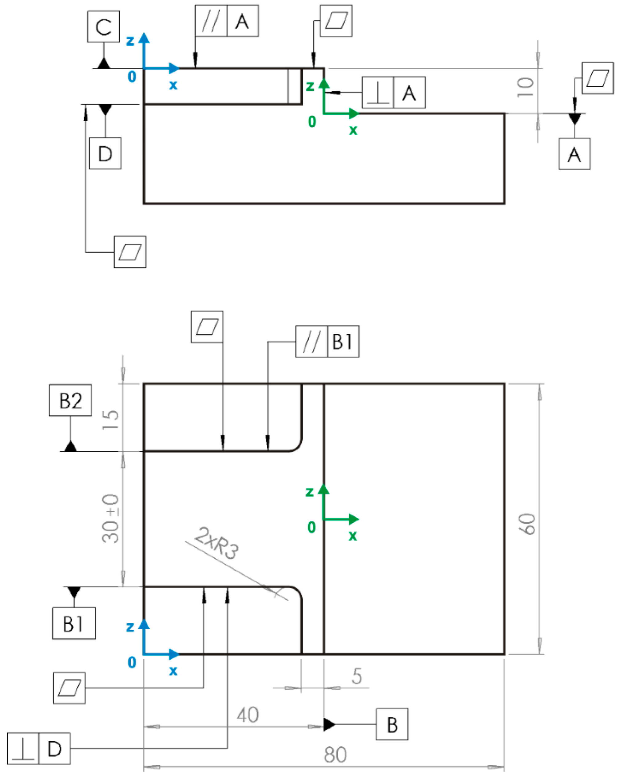
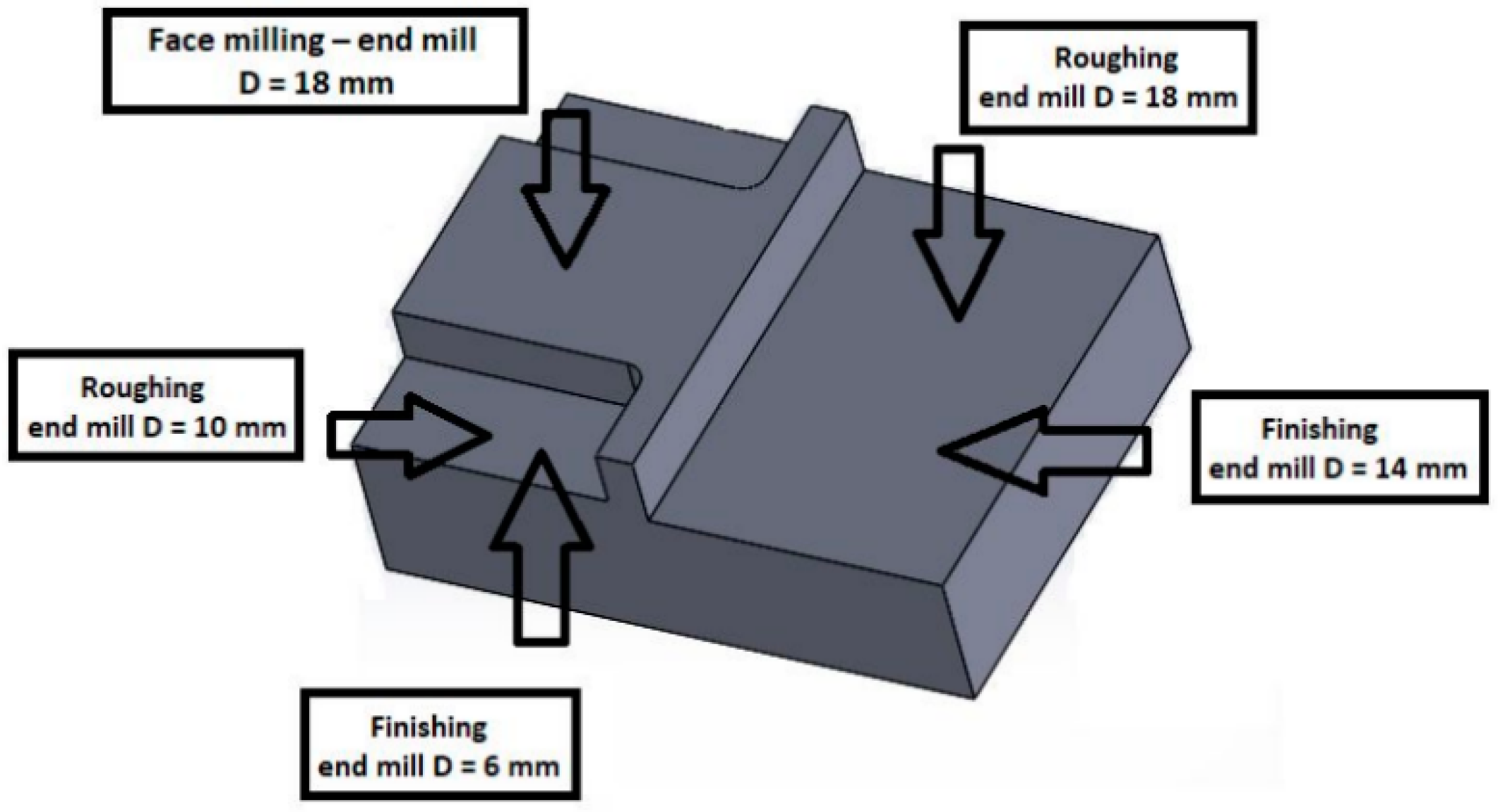
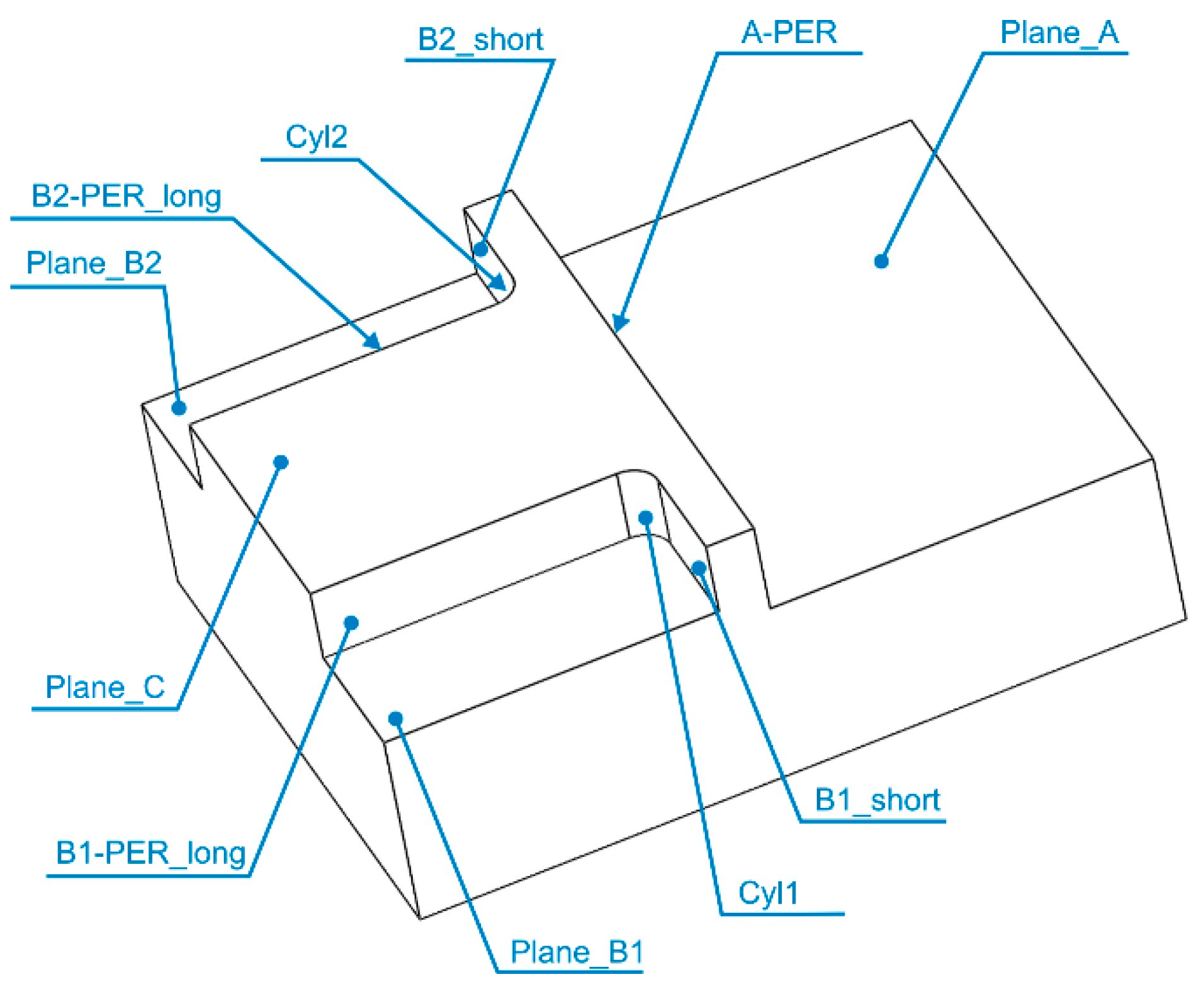
- Face milling of the top surface marked Plane C, in Figure 3, where the strategy zig-zag was used.
- Milling (roughing) a flat side surface marked Plane A, A-PER, where strategy contour with offset was used. After this operation, an allowance of 0.3 mm was left, which was removed by a tool with a smaller diameter.
- Milling (roughing) a two-sided surface marked Plane B1, B1-PER_long, Cyl1, B1_short, Plane B2, B2-PER_long, Cyl2, B2_short. After this operation, the allowance of 0.3 mm was left too and was removed by a tool with a smaller diameter.
2.3. Programming NC Program
3. Measurement of Geometrical Characteristics
4. Evaluations of Geometrical Characteristics
- Flatness—horizontal planes;
- Flatness—vertical planes;
- Perpendicularity—planes;
- Perpendicularity—cylinders;
- Parallelism;
- Distance.
5. Results
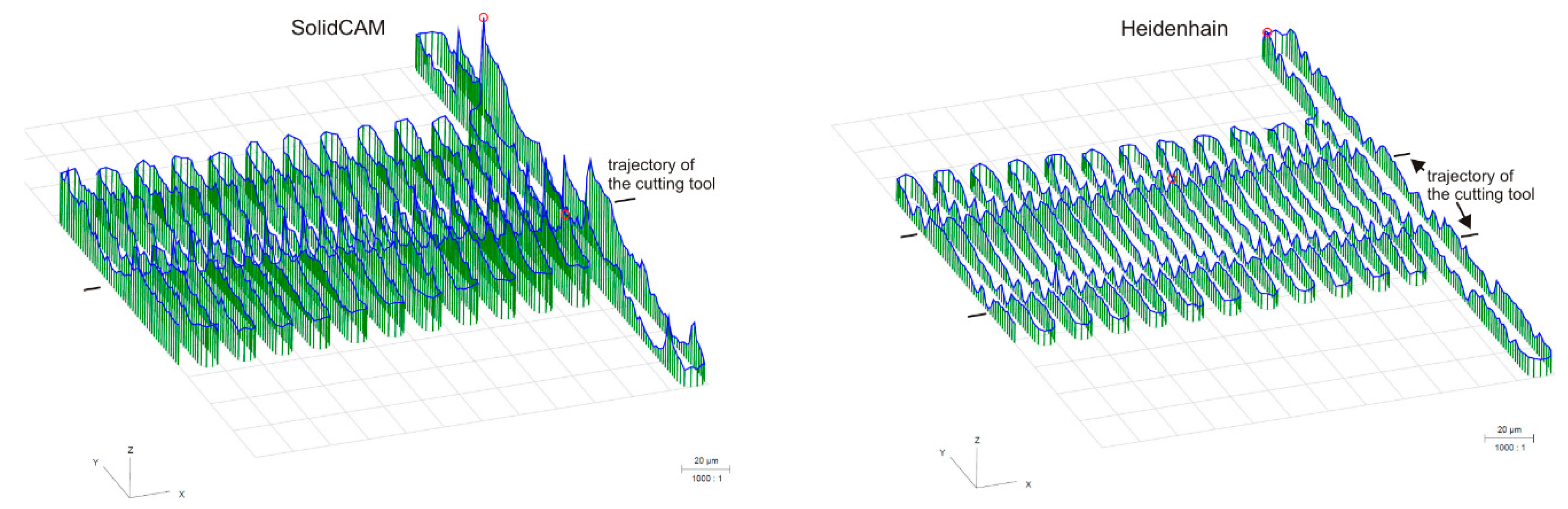
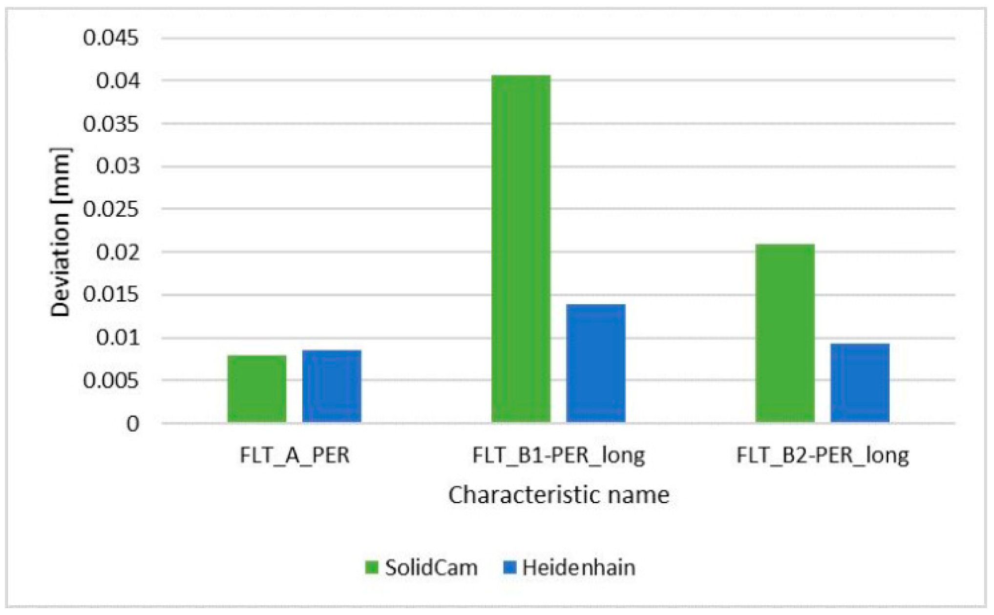
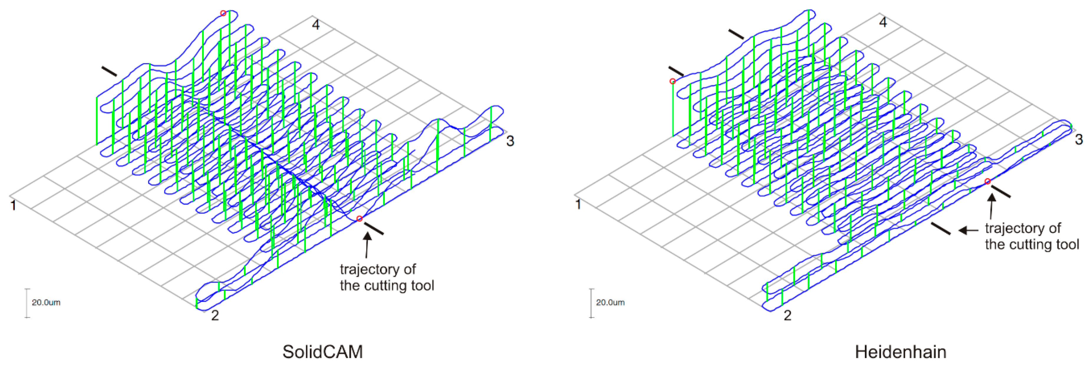
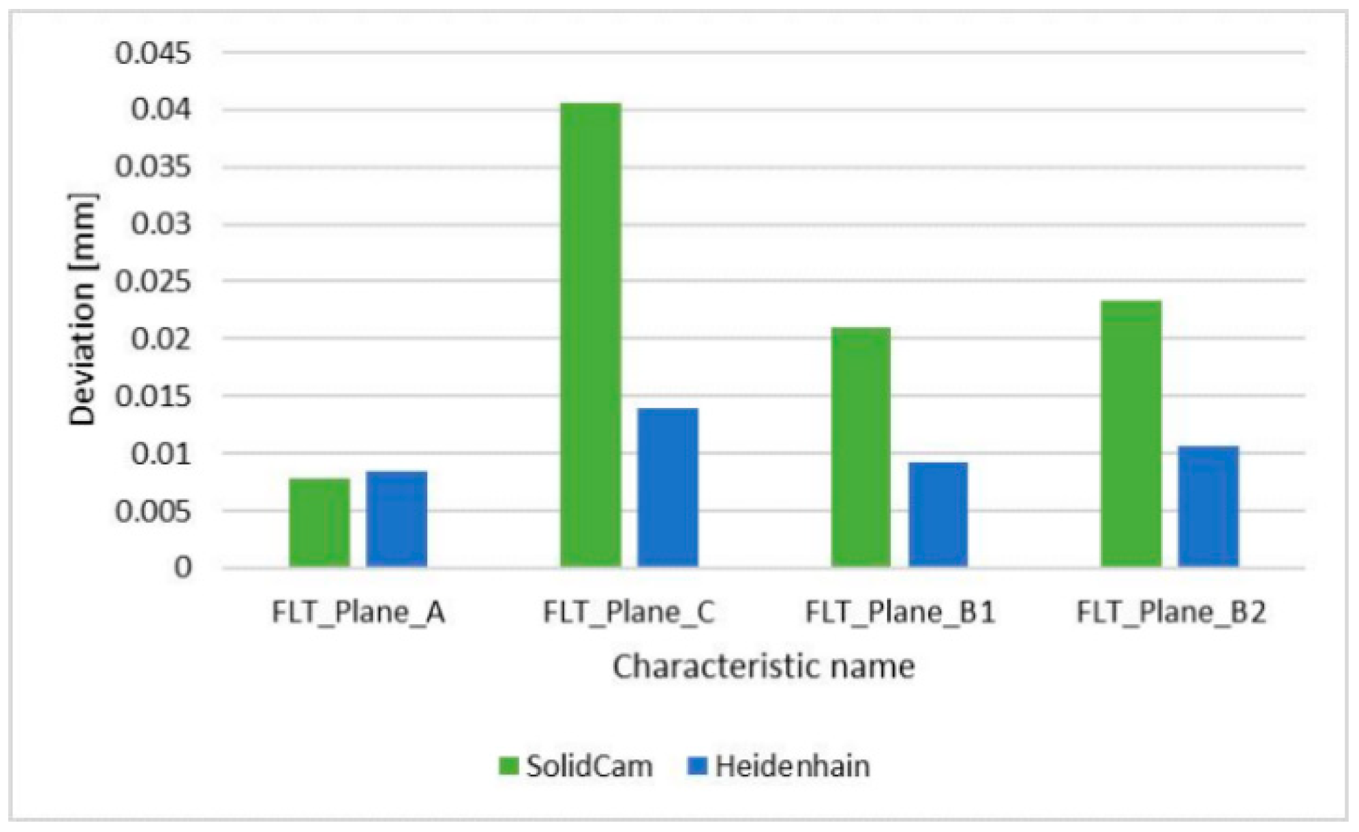
- The flatness comparison of the surfaces showed that the average flatness value for all surfaces was 0.023 mm for SolidCAM and 0.011 mm for Heidenhain. Average deviations in CAM system were significantly influenced by the flatness of plane Plane_C, which was higher than in system Heidenhain TNC 426. The comparison of the two systems in Plane_C showed the difference in the height deviations of flatness. In the CAM system, SolidCAM, where the tool overlap was 50%, the trajectory of the cutting tool was clearly visible. In the control system Heidenhain, where a tool overlap of 70% was used, the trajectory of tool was still visible, but the deviations from ideal plane were smaller. The Heidenhain control system showed more even height differences, which can be explained by the overlapping of the tool only during the milling process. The denser overlap of the toolpaths during machining increased the number of passes to machine the surface, which increased the milling time, but the surface showed better results in terms of flatness.
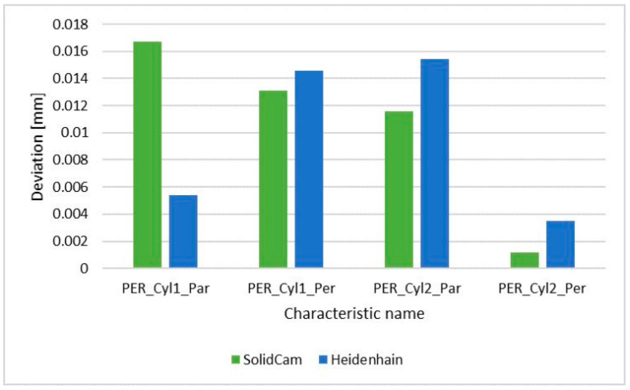
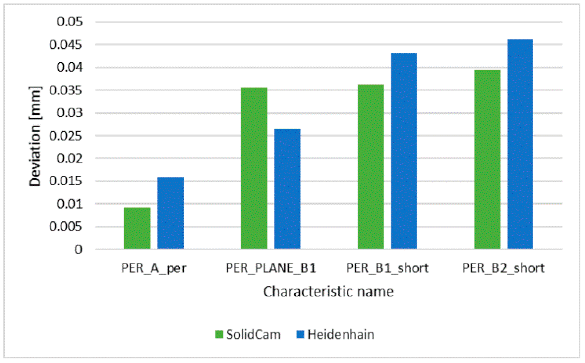
- The comparison of the geometric tolerances of perpendicularity showed that the average value for the SolidCAM system was 0.020 mm and for the Heidenhain TNC 426 system 0.020 mm, so there were no significant differences between them.
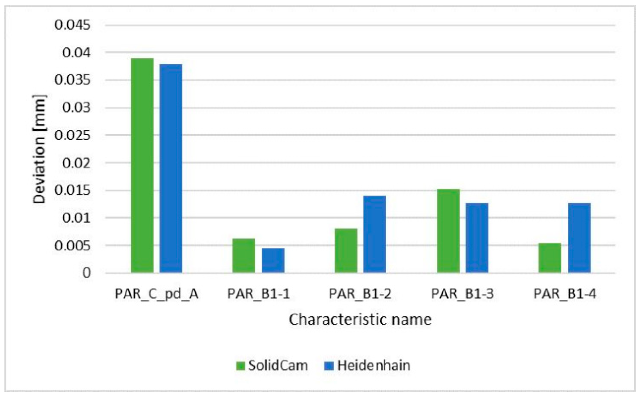
- The parallelism comparison in a global view also did not show a significant difference between the systems. For SolidCAM, the average deviation was 0.015 mm, and for Heidenhain, 0.016 mm. The comparison of the two systems in PAR_C_pd_A showed the difference in the distribution of deviations of parallelism. In the CAM system, SolidCAM, where the tool overlap was 50%, a greater surface waviness was observed than in the case of the Heidenhain system, where the tool overlap was 70%. The Heidenhain control system showed a lower surface waviness of the measured deviations of parallelism compared to the CAM system, SolidCAM, where the surface was machined earlier, but the deviations of parallelism were larger in this case. This was demonstrated by the greater surface waviness of the machined surface.
- The total average deviation, including all geometric tolerances, was 0.020 mm for SolidCAM and 0.016 mm for Heidenhain TNC 426. The result was significantly affected by flatness, where the SolidCAM system showed significantly higher values in all other comparisons than Heidenhain.
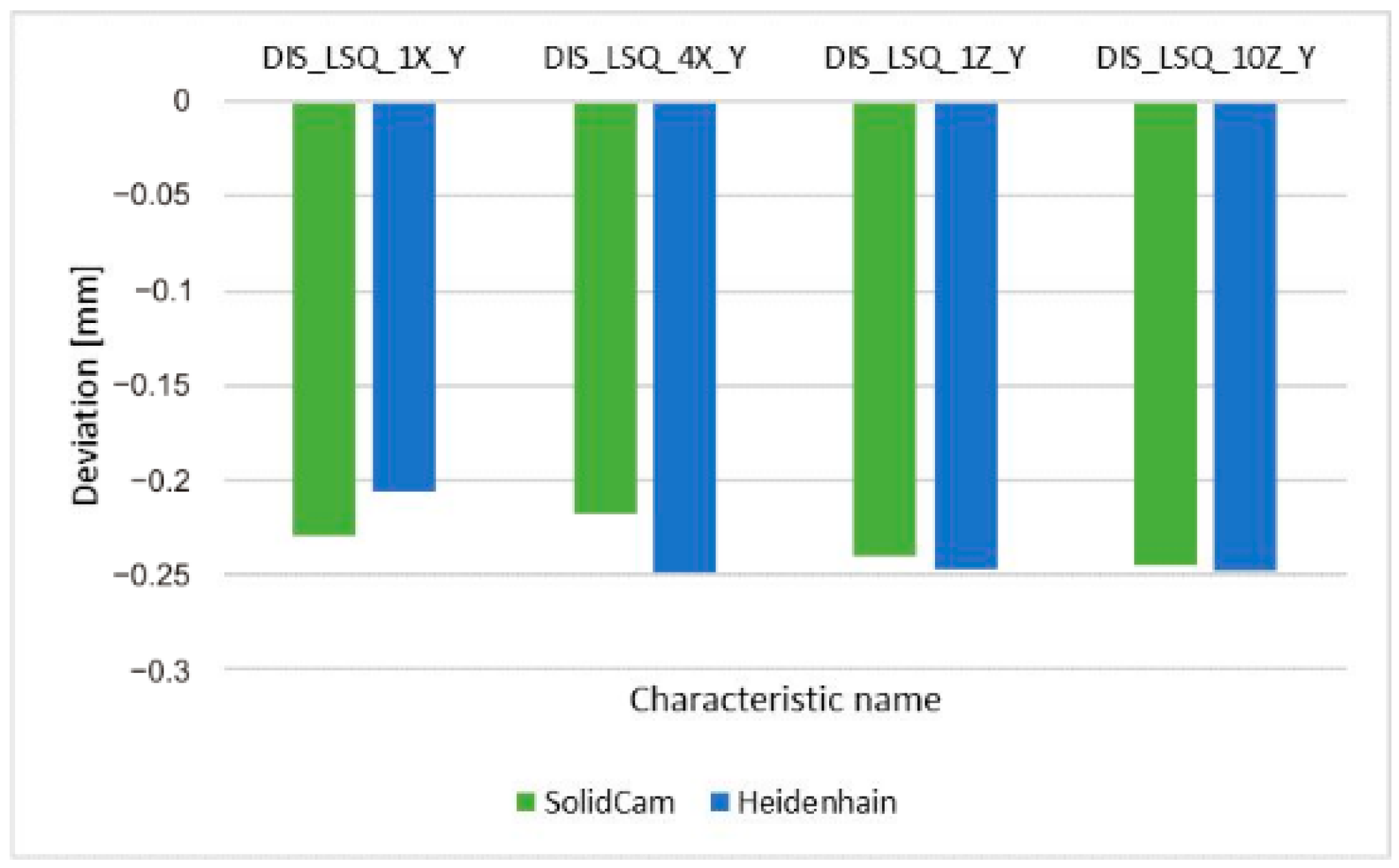
- For dimensional control, measurements between parallel surfaces B1_per-long and B2_per-long were realized. The average deviation for SolidCam was −0.233 mm, and for Heidenhain, −0.237 mm, so this was an inappreciable difference.
- There was a significant difference in production time, with SolidCAM 25 min and 30 s, and Heidenhain 48 min and 19 s. In accordance with these findings, the SolidCAM system is more suitable for production.
6. Conclusions
Author Contributions
Funding
Institutional Review Board Statement
Informed Consent Statement
Data Availability Statement
Conflicts of Interest
References
- Vaško, M.; Sága, M.; Majko, J.; Vaško, A.; Handrik, M. Impact Toughness of FRTP Composites Produced by 3D Printing. Materials 2020, 13, 5654. [Google Scholar] [CrossRef]
- Peterka, J.; Pokorny, P.; Vaclav, S.; Patoprsty, B.; Vozar, M. Modification of Cutting Tools by Drag Finishing. MM Sci. J. 2020, 2020, 3822–3825. [Google Scholar] [CrossRef]
- Turley, S.P.; Diederich, D.M.; Jayanthi, B.K.; Datar, A.; Ligetti, C.B.; Finke, D.A.; Saldana, C.; Joshi, S. Automated Process Planning and CNC-Code Generation. In Proceedings of the IIE Annual Conference and Expo 2014, Montreal, QC, Canada, 31 May–3 June 2014; Institute of Industrial and Systems Engineers (IISE): Norcross, GA, USA, 2014; pp. 2138–2144. [Google Scholar]
- Božek, P. Optimiziranje Putanje Robota Kod Točkastog Zavarivanja u Industriji Motornih Vozila—Robot Path Optimization for Spot Welding Applications in Automotive Industry. Teh. Vjesn. 2013, 20, 913–917. [Google Scholar]
- Peterka, J.; Pokorny, P.; Vaclav, S. CAM Strategies and Surfaces Accuracy. Ann. DAAAM Proc. 2008, 19, 1061–1063. [Google Scholar]
- López De Lacalle, L.N.; Lamikiz, A.; Muñoa, J.; Salgado, M.A.; Sánchez, J.A. Improving the High-Speed Finishing of Forming Tools for Advanced High-Strength Steels (AHSS). Int. J. Adv. Manuf. Technol. 2006, 29, 49–63. [Google Scholar] [CrossRef]
- Laspas, T. Modeling and Measurement of Geometric Error of Machine Tools: Methodology and Implementation; Royal Institute of Technology: Stockholm, Sweden, 2014. [Google Scholar]
- Nadolny, K.; Kapłonek, W. Analysis of Flatness Deviations for Austenitic Stainless Steel Workpieces after Efficient Surface Machining. Meas. Sci. Rev. 2014, 14, 204–212. [Google Scholar] [CrossRef] [Green Version]
- Ali, S.H.R.; Mohamd, O.M. Dimensional and Geometrical Form Accuracy of Circular Pockets Manufactured for Aluminum, Copper and Steel Materials on CNC Milling Machine Using CMM. Int. J. Eng. Res. Africa 2015, 17, 64–73. [Google Scholar] [CrossRef]
- Vakondios, D.; Kyratsis, P.; Yaldiz, S.; Antoniadis, A. Influence of Milling Strategy on the Surface Roughness in Ball End Milling of the Aluminum Alloy Al7075-T6. Meas. J. Int. Meas. Confed. 2012, 45, 1480–1488. [Google Scholar] [CrossRef]
- López de Lacalle, L.N.; Lamikiz, A.; Salgado, M.A.; Herranz, S.; Rivero, A. Process Planning for Reliable High-Speed Machining of Moulds. Int. J. Prod. Res. 2002, 40, 2789–2809. [Google Scholar] [CrossRef]
- Vila, C.; Abellán-Nebot, J.V.; Siller-Carrillo, H.R. Study of Different Cutting Strategies for Sustainable Machining of Hardened Steels. Procedia Eng. 2015, 132, 1120–1127. [Google Scholar] [CrossRef] [Green Version]
- Varga, J.; Stahovec, J.; Beno, J.; Vrabeľ, M. Assessment of Surface Quality for Chosen Milling Strategies When Producing Relief Surfaces. Adv. Sci. Technol. Res. J. 2014, 8, 37–41. [Google Scholar] [CrossRef]
- Chen, Z.C.; Dong, Z.; Vickers, G.W. Automated Surface Subdivision and Tool Path Generation for 3 1/2 1/2-Axis CNC Machining of Sculptured Parts. Comput. Ind. 2003, 50, 319–331. [Google Scholar] [CrossRef]
- Ali, R.; Mia, M.; Khan, A.; Chen, W.; Gupta, M.; Pruncu, C. Multi-Response Optimization of Face Milling Performance Considering Tool Path Strategies in Machining of Al-2024. Materials 2019, 12, 1013. [Google Scholar] [CrossRef] [PubMed] [Green Version]
- Quinsat, Y.; Sabourin, L. Optimal Selection of Machining Direction for Three-Axis Milling of Sculptured Parts. Int. J. Adv. Manuf. Technol. 2007, 33, 684–692. [Google Scholar] [CrossRef] [Green Version]
- Sarma, S.E. Crossing Function and Its Application to Zig-Zag Tool Paths. CAD Comput. Aided Des. 1999, 31, 881–890. [Google Scholar] [CrossRef]
- Bílek, O.; Páč, J.; Lukovics, I.; Čop, J. CNC Machining: An Overview of Available CAM Processors. In Development in Machining Technology; Politechnika Krakowska: Krakow, Poland, 2014; pp. 75–89. ISBN 978-83-7242-765-6. [Google Scholar]
- Salihu, S.A. Influence of Magnesium Addition on Mechanical Properties and Microstructure of Al-Cu-Mg Alloy. IOSR J. Pharm. Biol. Sci. 2012, 4, 15–20. [Google Scholar] [CrossRef]
- Jalid, A.; Hariri, S.; Laghzale, N.E. Influence of Sample Size on Flatness Estimation and Uncertainty in Three-Dimensional Measurement. Int. J. Metrol. Qual. Eng. 2015, 6, 102. [Google Scholar] [CrossRef] [Green Version]
- Ali, S.H.R.; Mohamed, H.H.; Bedewy, M.K. Identifying Cylinder Liner Wear Using Precise Coordinate Measurements. Int. J. Precis. Eng. Manuf. 2009, 10, 19–25. [Google Scholar] [CrossRef]
- Pathak, V.K.; Kumar, S.; Nayak, C.; Gowripathi Rao, N. Evaluating Geometric Characteristics of Planar Surfaces Using Improved Particle Swarm Optimization. Meas. Sci. Rev. 2017, 17, 187–196. [Google Scholar] [CrossRef] [Green Version]
- Runje, B.; Marković, M.; Lisjak, D.; Medić, S.; Kondić, Ž. Integrated Procedure for Flatness Measurements of Technical Surfaces. Teh. Vjesn. 2013, 20, 113–116. [Google Scholar]
- Mikó, B.; Farkas, G.; Bodonyi, I. Investigation of Points Sampling Strategies in Case of Flatness. Cut. Tools Technol. Syst. 2019, 91, 143–156. [Google Scholar] [CrossRef]
- Hazarika, M.; Dixit, U.S.; Deb, S. Effect of Datum Surface Roughness on Parallelism and Perpendicularity Tolerances in Milling of Prismatic Parts. Proc. Inst. Mech. Eng. Part B J. Eng. Manuf. 2010, 224, 1377–1388. [Google Scholar] [CrossRef]
- Mikó, B.; Farkas, G. Comparison of Flatness and Surface Roughness Parameters When Face Milling and Turning. In Development in Machining Technology; Zebala, W., Manková, I., Eds.; Cracow University of Technology: Cracow, Poland, 2017; Volume 7, pp. 18–27. [Google Scholar]
- Gapinski, B.; Zachwiej, I.; Kolodziej, A. Comparison of Different Coordinate Measuring Devices for Part Geometry Control. In Proceedings of the Digital Industrial Radiology and Computed Tomography (DIR 2015), Ghent, Belgium, 22–25 June 2015; NDT: Ghent, Belgium, 2015. [Google Scholar]
- Rangarajan, A.; Dornfeld, D. Efficient Tool Paths and Part Orientation for Face Milling. CIRP Ann. Manuf. Technol. 2004, 53, 73–76. [Google Scholar] [CrossRef] [Green Version]
- Dobrzynski, M.; Chuchala, D.; Orlowski, K.A. The Effect of Alternative Cutter Paths on Flatness Deviations in the Face Milling of Aluminum Plate Parts. J. Mach. Eng. 2018, 18, 80–87. [Google Scholar] [CrossRef] [Green Version]
- Gusev, V.G.; Morozov, A.V. Deviation from Flatness of Surfaces after Combined Peripheral Grinding. In Proceedings of the MATEC Web of Conferences, Sevastopol, Russia, 10–14 September 2018; EDP Sciences: Les Ulis, France, 2018; Volume 224, p. 01028. [Google Scholar]
- Sheth, S.; George, P.M. Experimental Investigation and Prediction of Flatness and Surface Roughness During Face Milling Operation of WCB Material. Procedia Technol. 2016, 23, 344–351. [Google Scholar] [CrossRef] [Green Version]
- Gapinski, M.; Grzelka, P.D.M.; Rucki, P.D.M. The Accuracy Analysis of the Roundness Measurement with Coordinate Measuring Machines. In Proceedings of the XVIII IMEKO World Congress, Metrology for a Sustainable Development, Rio de Janeiro, Brazil, 17–22 September 2006. [Google Scholar]
- Mikó, B. Measurement and Evaluation of the Flatness Error of a Milled Plain Surface. In Proceedings of the IOP Conference Series: Materials Science and Engineering, Kecskemét, Hungary, 7–8 June 2018; Institute of Physics Publishing: Bristol, UK, 2018; Volume 448, p. 012007. [Google Scholar]
- Mikó, B.; Drégelyi-Kiss, Á. Study on Tolerance of Shape and Orientation in Case of Shoulder Milling. In Development in Machining Technology; Zębala, W., Mankova, I., Eds.; Cracow University of Technology: Cracow, Poland, 2015; pp. 136–150. [Google Scholar]
- Lakota, S.; Görög, A. Flatness Measurement by Multi-Point Methods and by Scanning Methods. Ad Alta J. Interdiscip. Res. 2011, 1, 124–127. [Google Scholar]
- Kawalec, A.; Magdziak, M. An Influence of the Number of Measurement Points on the Accuracy of Measurements of Free-Form Surfaces on CNC Machine Tool. Adv. Manuf. Sci. Technol. 2011, 35, 17–27. [Google Scholar]
- Mikó, B. Assessment of Flatness Error by Regression Analysis. Meas. J. Int. Meas. Confed. 2021, 171, 108720. [Google Scholar] [CrossRef]
- Nowakowski, L.; Skrzyniarz, M.; Blasiak, S.; Bartoszuk, M. Influence of the Cutting Strategy on the Temperature and Surface Flatness of the Workpiece in Face Milling. Materials 2020, 13, 4542. [Google Scholar] [CrossRef]
- Toh, C.K. A Study of the Effects of Cutter Path Strategies and Orientations in Milling. J. Mater. Process. Technol. 2004, 152, 346–356. [Google Scholar] [CrossRef]


| Chemical Composition | Content [%] |
|---|---|
| Cu | 4.30 |
| Mg | 0.79 |
| Fe | 0.26 |
| Si | 0.24 |
| Mn | 0.3 |
| Ti | 0.04 |
| Zn | 0.04 |
| Al | balance |
| Tool Diameter [mm] | Cutting Speed [m·min−1] | Feed per Tooth [mm] | Spindle Frequency [RPM] | Tool Producer | Tool Code |
|---|---|---|---|---|---|
| End Mill D 18 | 270 | 0.125 | 4800 | Korloy | AMS2018S |
| End Mill D 14 | 299 | 0.021 | 4800 | ZPS-FN | 120517 |
| End Mill D 10 | 232 | 0.03 | 4800 | ZPS-FN | 270618 |
| End Mill D 6 | 259 | 0.03 | 4600 | ZPS-FN | 273618 |
| Name | Deviation SolidCam [mm] | Deviation Heidenhain [mm] |
|---|---|---|
| FLT_Plane_A | 0.0079 | 0.0085 |
| FLT_Plane_C | 0.0406 | 0.0139 |
| PAR_C_pd_A | 0.0389 | 0.0379 |
| FLT_Plane_B1 | 0.0210 | 0.0093 |
| FLT_Plane_B2 | 0.0233 | 0.0106 |
| FLT_A-PER | 0.0056 | 0.0107 |
| PER_A_per | 0.0092 | 0.0159 |
| Distance_LSQ_1X_Y | −0.2299 | −0.2056 |
| Distance_LSQ_4X_Y | −0.2179 | −0.2486 |
| Distance_LSQ_1Z_Y | −0.2400 | −0.2471 |
| Distance_LSQ_10Z_Y | −0.2455 | −0.2477 |
| FLT_B1-PER_long | 0.0315 | 0.0156 |
| FLT_B2-PER_long | 0.0167 | 0.0256 |
| PAR_B1_per-long_1 | 0.0063 | 0.0045 |
| PAR_B1_per-long_2 | 0.0081 | 0.0141 |
| PAR_B1_per-long_3 | 0.0152 | 0.0127 |
| PAR_B1_per-long_4 | 0.0054 | 0.0126 |
| PER_Plane_B1_PER_long_pd_PER | 0.0355 | 0.0266 |
| PER_B1_short_pd_B1 | 0.0362 | 0.0431 |
| PER_B2_short_pd_B2 | 0.0395 | 0.0463 |
| PER_Cyl1_Par_to_Plane_A_PER | 0.0167 | 0.0054 |
| PER_Cyl1_Per_to_Plane_A_PER | 0.0131 | 0.0146 |
| PER_Cyl2_Par_to_Plane_A_PER | 0.0116 | 0.0154 |
| PER_Cyl2_Per_to_Plane_A_PER | 0.0012 | 0.0035 |
| Evaluated Plane | Reference Plane | |
|---|---|---|
| PER_A_per | A-PER | Plane_A |
| PER_Plane_B1_PER_long_pd_PER | B1-PER_long | Plane_A |
| PER_B1_short_pd_B1 | B1_short | Plane_B1 |
| PER_B1_short_pd_B2 | B2_short | Plane_B2 |
| Evaluated Plane | Reference Plane | |
|---|---|---|
| PAR_C_pd_A | Plane_C | Plane_A |
| PAR_B1_per-long_1 | B2-PER_long | B1-PER_long |
| PAR_B1_per-long_2 | B2-PER_long | B1-PER_long |
| PAR_B1_per-long_3 | B2-PER_long | B1-PER_long |
| PAR_B1_per-long_4 | B2-PER_long | B1-PER_long |
Publisher’s Note: MDPI stays neutral with regard to jurisdictional claims in published maps and institutional affiliations. |
© 2021 by the authors. Licensee MDPI, Basel, Switzerland. This article is an open access article distributed under the terms and conditions of the Creative Commons Attribution (CC BY) license (http://creativecommons.org/licenses/by/4.0/).
Share and Cite
Varga, J.; Tóth, T.; Frankovský, P.; Dulebová, Ľ.; Spišák, E.; Zajačko, I.; Živčák, J. The Influence of Automated Machining Strategy on Geometric Deviations of Machined Surfaces. Appl. Sci. 2021, 11, 2353. https://doi.org/10.3390/app11052353
Varga J, Tóth T, Frankovský P, Dulebová Ľ, Spišák E, Zajačko I, Živčák J. The Influence of Automated Machining Strategy on Geometric Deviations of Machined Surfaces. Applied Sciences. 2021; 11(5):2353. https://doi.org/10.3390/app11052353
Chicago/Turabian StyleVarga, Ján, Teodor Tóth, Peter Frankovský, Ľudmila Dulebová, Emil Spišák, Ivan Zajačko, and Jozef Živčák. 2021. "The Influence of Automated Machining Strategy on Geometric Deviations of Machined Surfaces" Applied Sciences 11, no. 5: 2353. https://doi.org/10.3390/app11052353
APA StyleVarga, J., Tóth, T., Frankovský, P., Dulebová, Ľ., Spišák, E., Zajačko, I., & Živčák, J. (2021). The Influence of Automated Machining Strategy on Geometric Deviations of Machined Surfaces. Applied Sciences, 11(5), 2353. https://doi.org/10.3390/app11052353