On the Design of Continuously Variable Transmissions with Bidirectional Bridge Structures for Hybrid Vehicles
Abstract
:Featured Application
Abstract
1. Introduction
2. Basic Path Diagram (BPD)
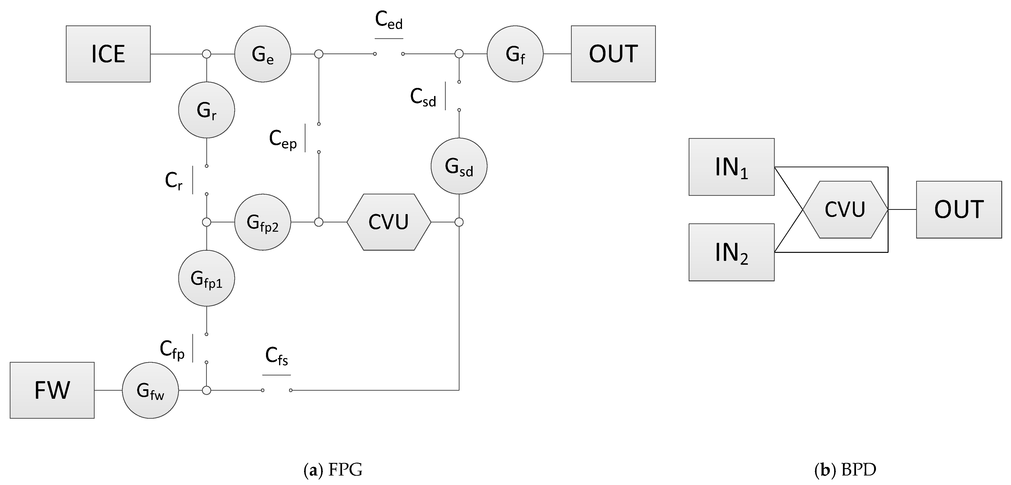
2.1. Function Power Graph (FPG)
2.2. BPD
- Rename the power input unit in the FPG as IN1, IN2, IN3…, etc., in sequence of their maximum power output if there are multiple power sources.
- Ignore the independent subsystems that have no connection with other transmission paths and are driven by a single power source. For example, the rear wheels of a vehicle are independently driven by an e-Axle module. This e-Axle module is purely powered by electric motor(s) and has no connection with other powertrain units such as the engine and the transmission. Hence, this e-Axle module needs to be completely ignored in this step.
- Ignore the auxiliary power input units that have no mechanical connection to the wheel or are unable to drive the wheel directly. Examples include electric motors that accelerate the flywheel to recharge its kinetic energy and superchargers that are driven by electric motors.
- Ignore all of the clutches, brakes, couplings, and torque converters.
- Ignore transmission units that have constant ratios or have step-variable ratios. These include gear trains, chain drives, belt drives, manual transmissions (MTs), automatic transmissions (ATs), and dual-clutch transmissions (DCTs).
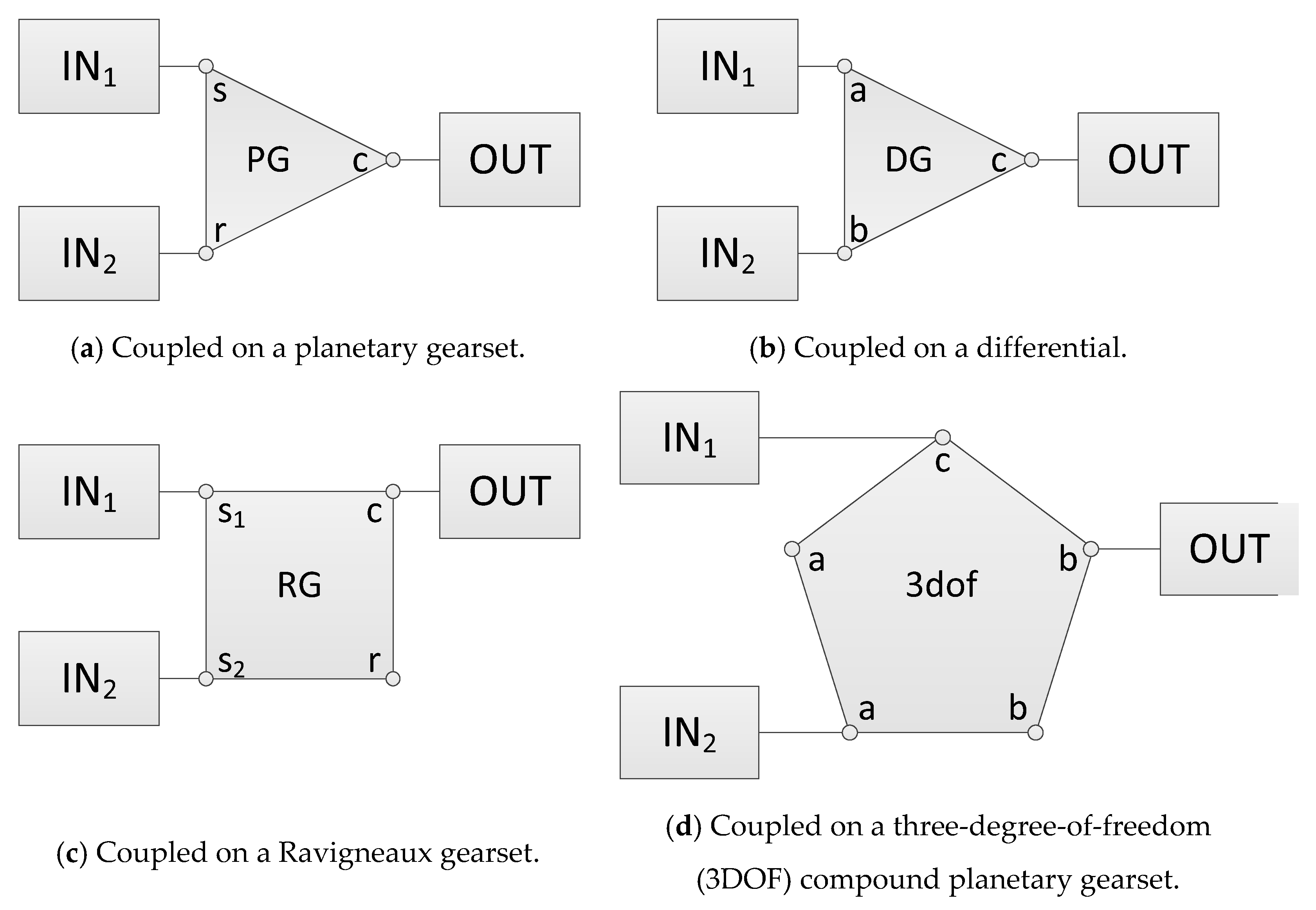
- If there are gearsets with multiple DOFs, such as planetary gearsets, differentials, and Ravigneaux gearsets, replace them with 2DOF-3E, 2DOF-4E, and MDOF.
- Locate the transmission paths that are only used for reversing and combine them with the transmission paths for low-gear forward drive.
- Combine the coupling points into adjacent basic units, such as IN, OUT, and CVU.
- Combine the remaining coupling points with adjacent ones.
- Adjust the orientation of the basic units, and avoid overlap and intersection of the connection lines that are parallel in the original FPG.
3. Classification of Systems
3.1. Direction of Power Flows through the CVU
3.2. Coupling Pattern of Power Inputs
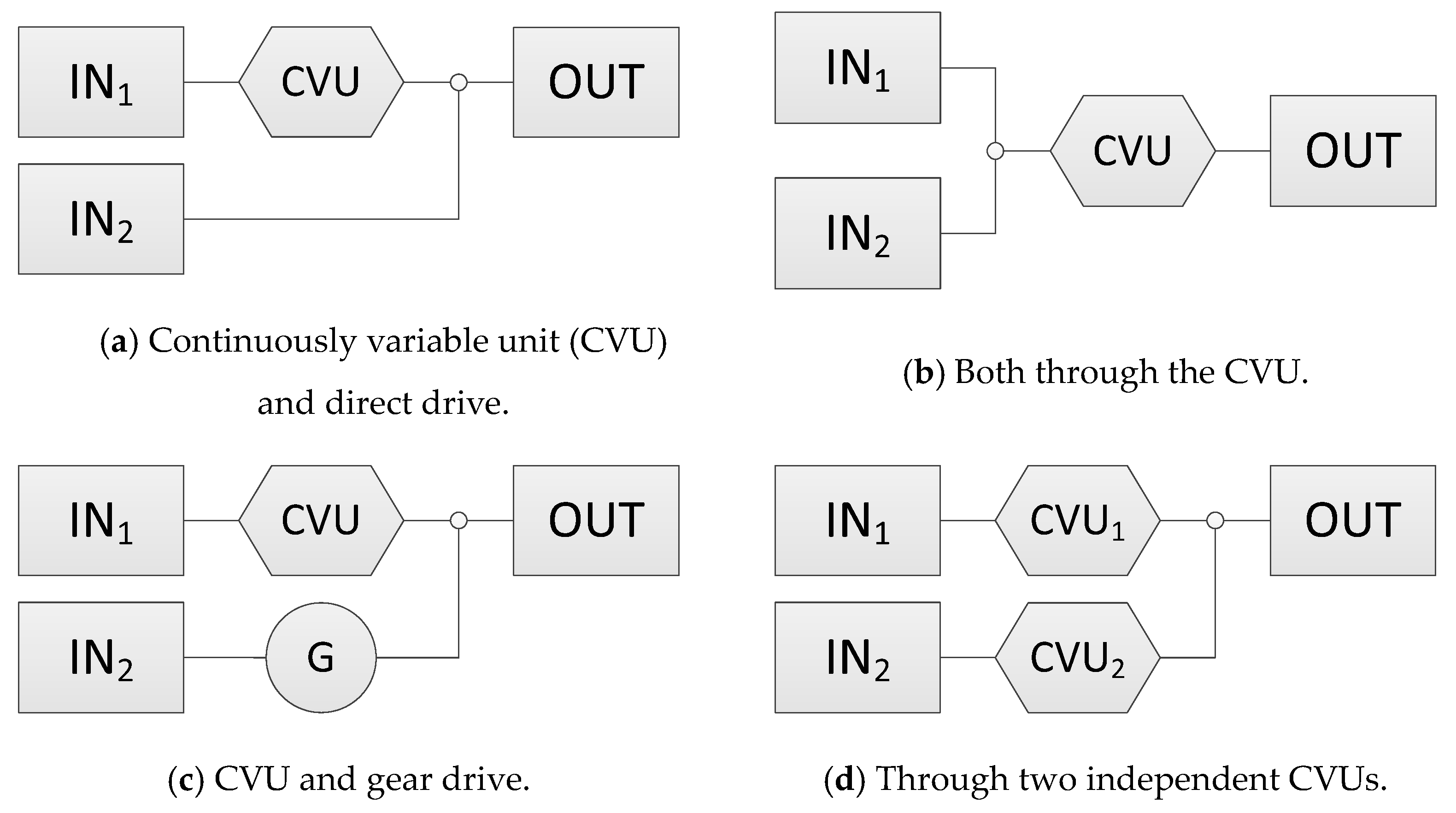
3.3. Number of Power Transmission Paths Parallel to the CVU
3.3.1. Power-Split-Type Dual-Path Systems
3.3.2. Bypass-Type Dual-Path Systems
3.4. Summary of System Classification
4. Analysis of Hybrid Systems with CVUs
5. System Synthesis and Example
- The system has at least two driving modes, and each of them is driven by one of the two inputs.
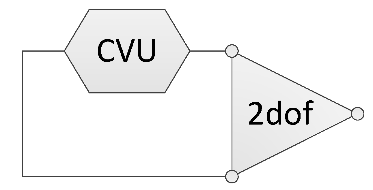
- In every driving mode, the power is transmitted by the power-split mechanism formed by the loop structure comprising the CVU and the 2DOF unit to have a higher torque capacity than the CVU.
- The transition between the two driving modes should be seamless. At the mode switching point, the CVU ratios in the two modes need to be the same. Therefore, the ratio range of the two modes should be joined together or have a small overlap region.
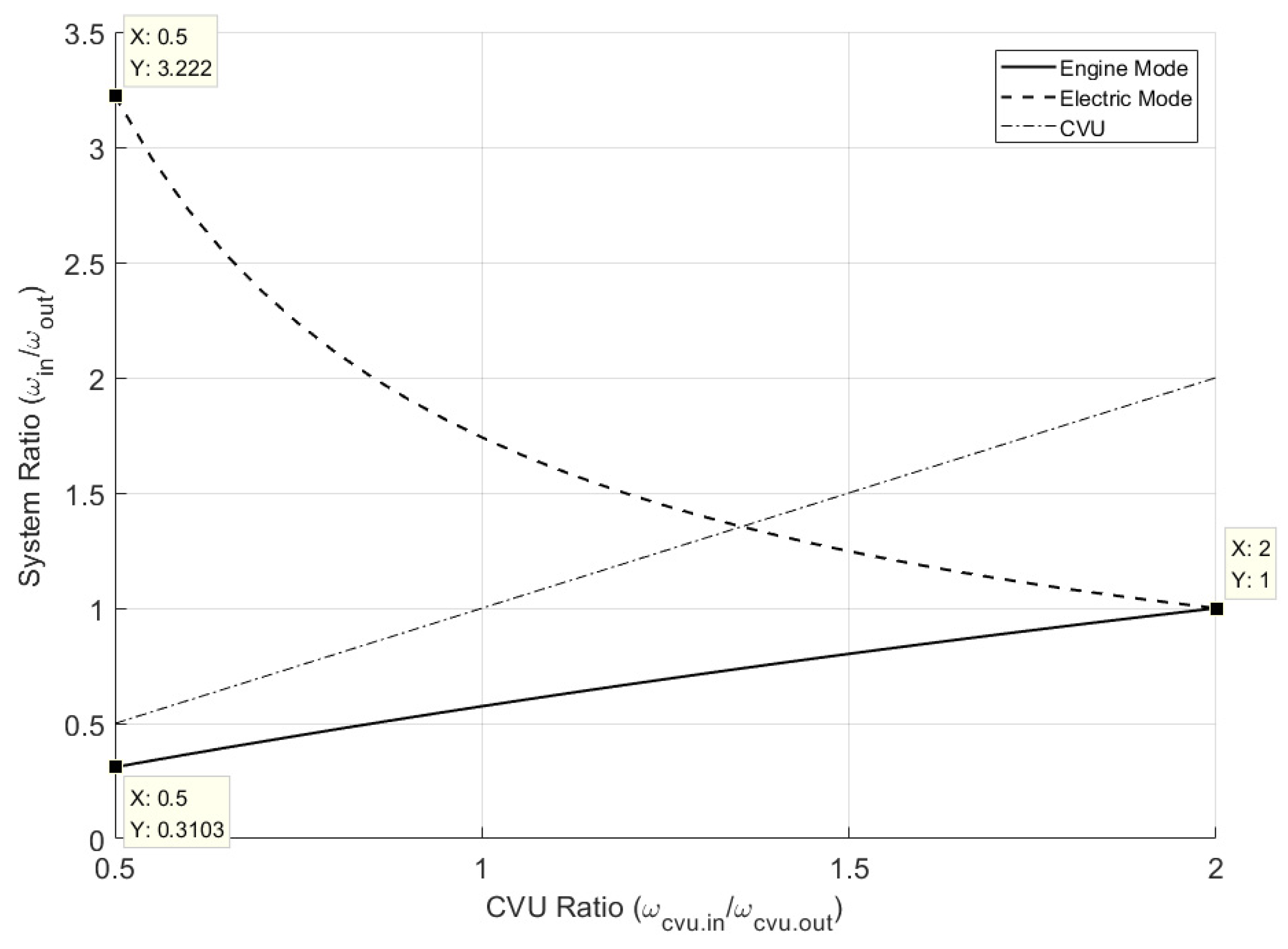
6. Results
7. Conclusions
- Direction of power flows through the CVU: One-way manipulated and dual-way manipulated systems. A bidirectional bridge structure comprising the CVU is required in the BPD for a dual-way manipulated system, which can exploit twice the ratio coverage of the CVU.
- Coupling pattern of the power inputs: Direct-coupled and planetary gear-coupled systems. The power sources of a planetary gear-coupled system are connected to different elements of an MDOF unit.
- Number of power transmission paths parallel to the CVU: Single-path, bypass-type dual-path, and power-split-type dual-path systems. In the BPD, a loop structure comprising only the CVU is required for a bypass-type dual-path system. For a power-split-type dual-path system, the loop structure should comprise a CVU and an MDOF unit.
Author Contributions
Funding
Data Availability Statement
Acknowledgments
Conflicts of Interest
References
- Global Automotive Transmission Type Market Share between 2015 and 2025. Available online: https://www.statista.com/statistics/204123/transmission-type-market-share-in-automobile-production-worldwide/ (accessed on 25 February 2021).
- Automotive Transmission Market Size Worth $281.3 Bn by 2026. Available online: https://www.gminsights.com/pressrelease/automotive-transmission-market (accessed on 25 February 2021).
- Automotive Automatic Transmission Market—Growth, Trends, COVID-19 Impact, and Forecasts (2021–2026). Available online: https://www.mordorintelligence.com/industry-reports/automotive-automatic-transmission-market (accessed on 25 February 2021).
- Automotive Transmission Market, Size, Share, Opportunities and Forecast, 2020–2027. Available online: https://www.datamintelligence.com/research-report/automotive-transmission-market (accessed on 25 February 2021).
- Dugger, G.L.; Brandt, A.; George, J.F.; Perini, L.L. Flywheel and flywheel/heat engine hybrid propulsion systems for low-emission vehicles. In Proceedings of the Intersociety Energy Conversion Engineering Conference, Boston, MA, USA, 3–5 August 1971. [Google Scholar]
- Frank, A.; Beachley, N. Improved fuel economy in automobiles by use of a flywheel energy management system. In Proceedings of the 1975 Flywheel Technology Symposium, Berkeley, CA, USA, 10–12 November 1975; Available online: https://apps.dtic.mil/sti/pdfs/ADA301672.pdf#page=83 (accessed on 11 January 2021).
- Loscutoff, W.V. Flywheel/Heat Engine Power for an Energy-Economic Personal Vehicle; Battelle Pacific Northwest Labs.: Richland, WA, USA, 1976. [Google Scholar] [CrossRef] [Green Version]
- Hagin, F.; Merker, P. Drive systems with brake-energy recovery. In Proceedings of the First International Automotive Fuel Economy Research Conference, Washington, DC, USA, 31 October–2 November 1979; pp. 416–423. Available online: https://trid.trb.org/view/184357 (accessed on 11 January 2021).
- Greenwood, C.J. Integration of a Commercial Vehicle Regenerative Braking Driveline, C191/86, IMechE 86; Leyland Vehicles: Leyland, UK; Preston, UK; Lancashire, UK, 1986. [Google Scholar]
- Schilke, N.A.; DeHart, A.O.; Hewko, L.O.; Matthews, C.C.; Pozniak, D.J.; Rohde, S.M. The Design of an Engine-Flywheel Hybrid Drive System for a Passenger Car. Proc. Inst. Mech. Eng. Part D Transp. Eng. 1986, 200, 231–248. [Google Scholar] [CrossRef]
- van der Graaf, R. An ic engine-flywheel hybrid drive for road vehicles. In Proceedings of the International Conference on New Developments in Power Train and Chassis Engineering, Strasbourg, France, 3–5 June 1987; EAEC Paper 87031. pp. 150–167. [Google Scholar]
- Spijker, E. Steering and Control of a CVT Based Hybrid Transmission for a Passenger Car. Ph.D. Thesis, Technische Universiteit Eindhoven, Eindhoven, The Netherlands, 1994. [Google Scholar] [CrossRef]
- Kok, D.B. Design Optimisation of a Flywheel Hybrid Vehicle. Ph.D. Thesis, Technische Universiteit Eindhoven, Eindhoven, The Netherlands, 1999. [Google Scholar] [CrossRef]
- Hofman, T.; van Druten, R.; Serrarens, A.; van Baalen, J. A fundamental case study on the Prius and IMA drivetrain concepts. In Proceedings of the 21st International Battery, Hybrid and Fuel Cell Electric Vehicle Symposium & Exposition (EVS 21), Monaco, 2–6 April 2005; Available online: http://mate.tue.nl/mate/pdfs/4996.pdf (accessed on 11 January 2021).
- Oba, H.; Yamanaka, A.; Katsuta, H.; Kamichi, K. Development of a Hybrid Powertrain System Using CVT in a Minivan; SAE Technical Paper 2002-01-0991; SAE International: Warrendale, PA, USA, 2002. [Google Scholar] [CrossRef]
- Gomez, M.; Mucino, V.; Clark, N.; Smith, J. A Configuration for a Continuously Variable Power-Split Transmission in Hybrid-Electric Vehicle Applications; SAE Technical Paper 2004-01-0571; SAE International: Warrendale, PA, USA, 2004. [Google Scholar] [CrossRef]
- Höhn, B.; Pflaum, H.; Tomic, D. Fuel Consumption and Energy Balance of ‘Optimized CVT-Hybrid-Driveline’; SAE Technical Paper 2006-01-3259; SAE International: Warrendale, PA, USA, 2006. [Google Scholar] [CrossRef]
- Höhn, B.R.; Pinnekamp, B. The Autarc Hybrid: A Universal Power Train Concept for Passenger Cars. In Proceedings of the 1994 International Gearing Conference, Newcastle Upon Tyne, UK, 7–9 September 1994. [Google Scholar]
- Sheu, K.B.; Hsu, T.H.; Hsu, Y.Y. A Novel Parallel Hybrid Motorcycle Transmission. Mater. Sci. Forum 2006, 505–507, 1021–1026. [Google Scholar] [CrossRef]
- Ceraolo, M.; Caleo, A.; Capozzella, P.; Marcacci, M.; Carmignani, L. Operation and Performance of a Small Scooter with a Parallel-Hybrid Drive-train; SAE Technical Paper 2004-32-0077; SAE International: Warrendale, PA, USA, 2004. [Google Scholar] [CrossRef]
- He, L.; Wu, G.; Meng, X.; Sun, X. A novel continuously variable transmission flywheel hybrid electric powertrain. In Proceedings of the IEEE Vehicle Power and Propulsion Conference, Harbin, China, 3–5 September 2008. [Google Scholar] [CrossRef]
- Diego-Ayala, U.; Martinez-Gonzalez, P.; McGlashan, N.; Pullen, K.R. The mechanical hybrid vehicle: An investigation of a flywheel-based vehicular regenerative energy capture system. Proc. Inst. Mech. Eng. Part D J. Autom. Eng. 2008, 222, 2087–2101. [Google Scholar] [CrossRef]
- Brockbank, C.; Greenwood, C. Full-Toroidal Variable Drive Transmission Systems in Mechanical Hybrid Systems–From Formula 1 to Road Vehicles. 2009. Available online: https://www.semanticscholar.org/paper/Full-Toroidal-Variable-Drive-Transmission-Systems-%E2%80%93-Brockbank-Greenwood/e8f87fb57863b0827f52e0a62aa44a24a86e2c5a (accessed on 11 January 2021).
- Debal, P.; Faid, S.; Tricoche, L.; Bervoets, S. CVT-Based Full Hybrid Powertrain Offering High Efficiency at Lower Cost; SAE Technical Paper 2010-01-1313; SAE International: Warrendale, PA, USA, 2010. [Google Scholar] [CrossRef] [Green Version]
- Yanagisawa, T.; Yamanishi, T.; Utsugi, K.; Nagatsuyu, T. Development of Idling Stop System for 125 cm3 Scooters with Fuel Injection; SAE Technical Paper 2010-32-0121; SAE International: Warrendale, PA, USA, 2010. [Google Scholar] [CrossRef]
- Trivić, I. Comparative Analysis of Alternative Hybrid Systems for Automotive Applications. Ph.D. Thesis, University of Bologna, Bologna, Italy, 2012. [Google Scholar] [CrossRef]
- Osone, T.; Seiji, T.; Yamamoto, T.; Konagaya, F. Development of Jatco CVT8 Hybrid for Infiniti JX and Nissan Pathfinder; SAE Technical Paper 2014-01-1788; SAE International: Warrendale, PA, USA, 2014. [Google Scholar] [CrossRef]
- Götz, A.; Lauinger, C.; Walter, B.; Finsterbusch, M. Efficient CVT for Plug-in Hybrid Vehicles. ATZ Worldw. Novemb. 2016 2016, 118, 26–31. [Google Scholar] [CrossRef]
- Hu, J.; Mei, B.; Peng, H.; Jiang, X. Optimization Design and Analysis for a Single Motor Hybrid Powertrain Configuration with Dual Planetary Gears. Appl. Sci. 2019, 9, 707. [Google Scholar] [CrossRef] [Green Version]
- Bongermino, E.; Tomaselli, M.; Monopoli, V.G.; Rizzello, G.; Cupertino, F.; Naso, D. Hybrid Aeronautical Propulsion: Control and Energy Management. IFAC-PapersOnLine 2017, 50, 169–174. [Google Scholar] [CrossRef]
- Dedicated Hybrid Transmission. Available online: http://schaeffler-events.com/symposium/lecture/h6/index.html (accessed on 11 January 2021).
- Beachley, N.H.; Frank, A.A. Continuously Variable Transmissions: Theory and Practice; Lawrence Livermore National Lab.: Livermore, CA, USA, 1979. [Google Scholar] [CrossRef] [Green Version]
- Beachley, N.H.; Anscomb, C.; Burrows, C.R. Evaluation of split-path extended range continuously-variable transmissions for automotive applications. J. Frankl. Inst. 1984, 317, 235–262. [Google Scholar] [CrossRef]
- Hsieh, L.C.; Yan, H.S. On the mechanical efficiency of continuously variable transmissions with planetary gear trains. Int. J. Veh. Des. 1990, 11, 176–187. Available online: https://www.inderscience.com/info/inarticle.php?artid=61615 (accessed on 11 January 2021). [CrossRef]
- Chen, I.M.; Yang, T.H.; Liu, T. Function Power Graph—A Novel Methodology for Powertrain and Hybrid System Conceptual Design and Analysis. In Proceedings of the 2015 IFToMM World Congress, Taipei, Taiwan, 25–30 October 2015. [Google Scholar] [CrossRef]










| Unit | Symbol | Explanation | |
|---|---|---|---|
| Power I/O units | IN |  | Power input, such as an ICE, M/G, and flywheel (FW). |
| OUT |  | Power output, such as an individual wheel or final drive unit including the differential. | |
| Transmission unit | CVU |  | Transmission unit with continuously variable ratio. |
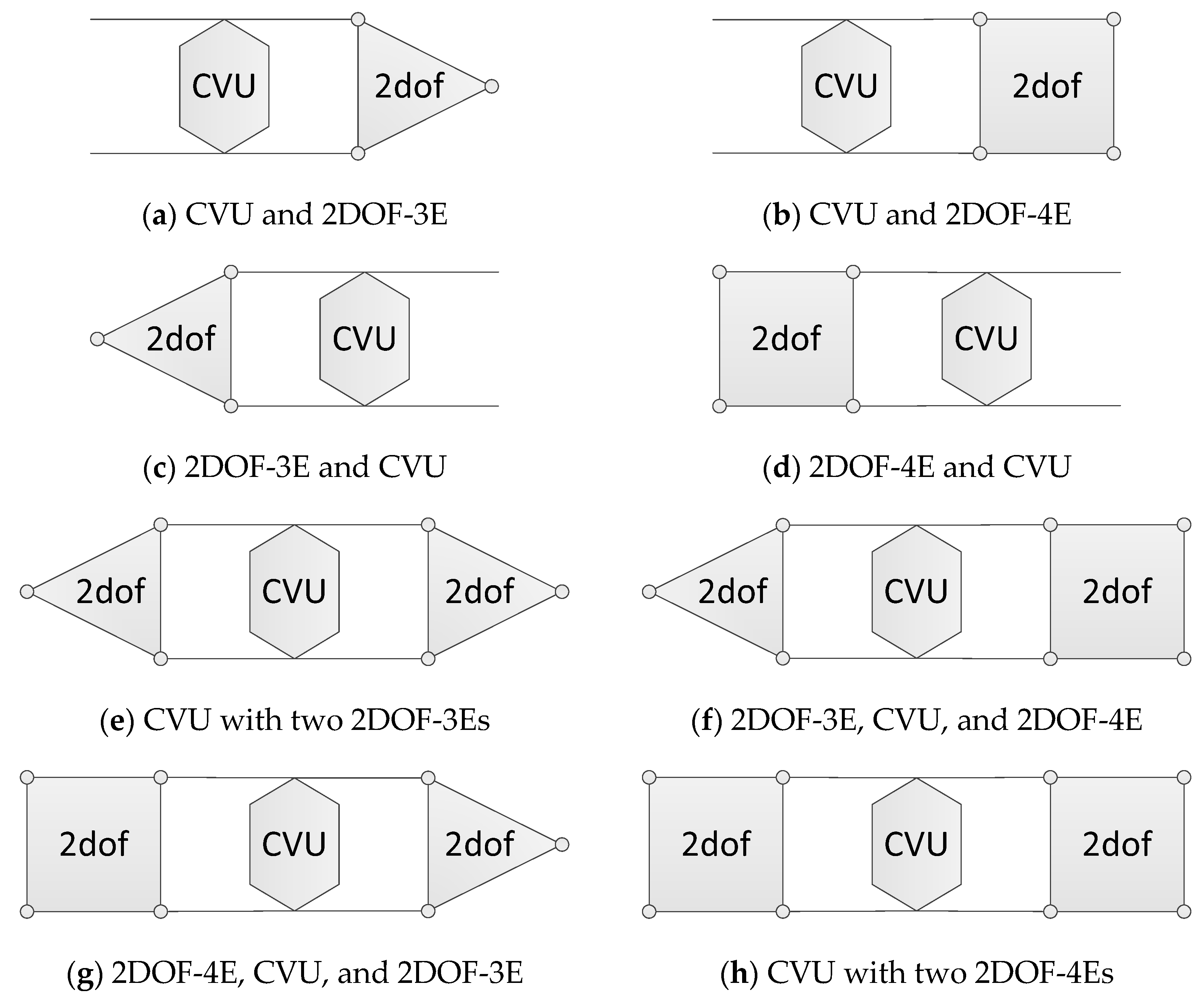
| Units with multiple degrees of freedom (DOFs) | 2DOF-3E |  | Two-degree-of-freedom (2DOF) gearset with three elements, such as planetary gearset (sun, ring, and carrier) or differential (bevel gear 1, 2, and carrier). |
| 2DOF-4E |  | 2DOF gearset with four elements, such as Ravigneaux planetary gearset (sun 1, sun 2, carrier, and ring). | |
| MDOF |  | Mechanism with more than three DOFs. | |
| Connection unit | Connection line |  | Power transmission path between units. |
| System | Required Structure | Required Structure in the BPD |
|---|---|---|
| Dual-way manipulated system | Bidirectional bridge structure |  |
| Power-split-type dual-path system | Loop structure with a CVU and MDOF unit |  |
| Bypass-type dual-path system | Loop structure with only a CVU | 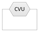 |
| Step | BPD | Effects on the System Property | |
|---|---|---|---|
| 1 | Select the loop structure with only the CVU as the base of the system. | 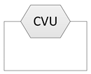 | The key component of the system is selected, and the features that the system may be able to achieve are determined. |
| 2 | Add the inputs and output into the system. | 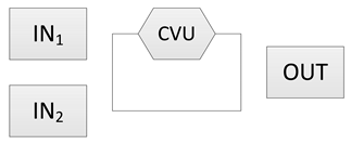 | The number of the power inputs and output is determined. |
| 3 | Connect the inputs and output with a loop structure. | 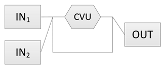 | The connecting pattern among the inputs, output, and other units determines the power flow patterns that the system can achieve. |
| 4 | Rearrange the layout of the connection lines. The complete BPD of the system is formed. | 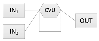 | After finishing the complete BPD, the possible power flow path of each driving mode can be formulated. If the desired power flow paths cannot be achieved, the designer can return to the previous step and reconnects the inputs and output to the system. |
| 5 | Determine the position of the coupling points. | 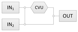 | The arrangement of the coupling points determines the positions where the power flows will split or merge in the system. Therefore, it can affect the final layout of the system. |
| 6 | Add the required clutches into the system. | 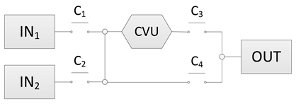 | The clutches and brakes serve as switches in the electronic circuit. They affect the load carrying and idling transmission paths in different driving modes, and this can affect the parasitic loss of the system. |
| 7 | Add the required the gearset(s) into the system. |  | The actual ratio of the system in different driving modes, and the total ratio coverage of the system are determined. |
| 8 | Determine the types of the power inputs. The complete FPG of the system is formed. | 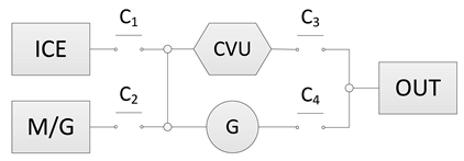 | The powering units of the system in each driving mode are determined. The designer needs to check again whether the desired power flow patterns of every driving mode can be realized by the finished clutches and brakes arrangement. |
| System Category: X-Y-Z | |||
|---|---|---|---|
| First letter (X) | Direction of power flows through the CVU | O | One-way manipulated |
| D | Dual-way manipulated | ||
| Second letter (Y) | Coupling pattern of the power inputs | D | Direct coupled |
| P | Planetary gear coupled | ||
| Third letter (Z) | Number of transmission paths parallel to the CVU | S | Single path |
| D | Dual path | ||
| Direction of Power Flows through the CVU | Coupling Pattern of the Power Inputs | Number of Transmission Paths Parallel to the CVU | |
|---|---|---|---|
| Single Path (-S) | Dual Path (-D) | ||
| One-way manipulated (O-) | Direct coupled (-D-) | O-D-S systems: (1971) Dugger [5] (1975) University of Wisconsin–Madison [6] (1976) Loscutoff [7] (1986) Greenwood [9] (1986) General Motors One-Mode Concept [10] (1999) Honda IMA [14] (2006) Sheu, K.B. [19] (2007) Piaggio HyS [20] (2008) Torotrak Flybrid [23] (2010) Punch HT1 [24] (2010) Honda ACG Starter [25] (2012) Trivić [26] (2013/15) Nissan/Jatco CVT8-Hybrid [27] (2018) Schaeffler DH-CVT [31] | O-D-D systems: (1981) MAN Gyrobus I [8] (2004) West Virginia University [16] (2008) Diego-Ayala [22] (2016) Schaeffler PHEV-CVT [28] |
| Planetary gear coupled (-P-) | O-P-S systems: (2001) Toyota THS-C [15] (2017) Chery Arrizo 7e [29] (2017) Saarland University [30] (2019) Chongqing University [29] | O-P-D systems: (1981) MAN Gyrobus II [5] (1999) TU/e ZI Powertrain [13] (2008) Tongji University [21] | |
| Dual-way manipulated (O-) | Direct coupled (-D-) | D-D-S systems: (1986) General Motors Two-Mode Concept [10] | D-D-D systems: (1987) TU/e [11,12] (2006) Technical University of Munich (TUM) [17,18] |
| Planetary gear coupled (-P-) | D-P-S systems: N.A. | D-P-D systems: N.A. | |
| Power source: IN1 Power receiver: OUT |  |  |
 |  | |
| Power source: IN2 Power receiver: OUT |  |  |
| Parameter | Description | Value |
|---|---|---|
| r1 | Ratio of gearset G1 | 0.5 |
| r2 | Ratio of gearset G2 | 2.0 |
| rp1 | Ratio of planetary gearset PG1 | 0.35 |
| rp2 | Ratio of planetary gearset PG2 | 0.35 |
| rcv.max | Maximum ratio of CVU | 2.0 |
| rcv.min | Minimum ratio of CVU | 0.5 |
Publisher’s Note: MDPI stays neutral with regard to jurisdictional claims in published maps and institutional affiliations. |
© 2021 by the authors. Licensee MDPI, Basel, Switzerland. This article is an open access article distributed under the terms and conditions of the Creative Commons Attribution (CC BY) license (http://creativecommons.org/licenses/by/4.0/).
Share and Cite
Kuo, H.-Y.; Liu, T. On the Design of Continuously Variable Transmissions with Bidirectional Bridge Structures for Hybrid Vehicles. Appl. Sci. 2021, 11, 2500. https://doi.org/10.3390/app11062500
Kuo H-Y, Liu T. On the Design of Continuously Variable Transmissions with Bidirectional Bridge Structures for Hybrid Vehicles. Applied Sciences. 2021; 11(6):2500. https://doi.org/10.3390/app11062500
Chicago/Turabian StyleKuo, Hsien-Yu, and Tyng Liu. 2021. "On the Design of Continuously Variable Transmissions with Bidirectional Bridge Structures for Hybrid Vehicles" Applied Sciences 11, no. 6: 2500. https://doi.org/10.3390/app11062500
APA StyleKuo, H.-Y., & Liu, T. (2021). On the Design of Continuously Variable Transmissions with Bidirectional Bridge Structures for Hybrid Vehicles. Applied Sciences, 11(6), 2500. https://doi.org/10.3390/app11062500


