Abstract
The research objective of this study was the seismic performance of double-row reinforced ceramsite concrete sandwich wall panels. The feasibility of upgrading a new wall panel from a non-load-bearing partition wall to a load-bearing seismic wall was examined by conducting cyclic load tests on five wall panel specimens. The test piece was a sandwich thermal insulation structure that could achieve a good protection distance between the thermal insulation material and the fire source so that the fire prevention problem could be solved. At the same time, the problem of easy fall-off of the insulation system was also solved. The specimens were divided into three groups, including three double-row reinforced ceramsite concrete sandwich wall panels with different dosages of alkali-resistant glass fiber, a double-row reinforced ordinary concrete sandwich wall panel, and a solid concrete ceramic wallboard. The effects of different dosages of alkali-resistant glass fiber, construction forms, and bearing side plate materials on the seismic performance of the sandwich wall panels were investigated separately for the specimens. From the analysis of the specimen results (damage characteristics, hysteresis curves, energy dissipation capacity, bearing capacity, ductility, longitudinal reinforcement strain, and stiffness degradation), it could be seen that among the five types of wallboard, the double-row reinforced ceramsite concrete sandwich wall panel with 0.3% fiber content had the best ductility and energy dissipation capacity. Adding fiber could solve or improve the problem of the low ultimate bearing capacity of ceramsite concrete as the wallboard’s bearing material. Compared with the same size solid ordinary concrete wallboard, the bearing capacity of the double-row reinforced ceramic concrete sandwich panel was slightly reduced. However, the additional seismic performance indexes were relatively superior. Through the analysis of the test results, it was shown that, when considering the thermal performance and seismic capacity, the new wall panel had good prospects for engineering applications.
1. Introduction
The material type or structural form of conventional wallboard is the fundamental factor used to determine its thermal insulation, heat insulation, and seismic performance. However, depending on the survey data, the heat transfer of the exterior wallboard accounts for about 30–45% of the total heat consumption of a building [,]. Moreover, winter heating in northern China only accounts for 52% of the total energy consumption of urban buildings []. Thus, to reduce energy consumption and achieve the goal of the green building, developing new sandwich wall panels as soon as possible is one of the most effective ways to solve the above problems [].
Sandwich wall panels originated in the 1990s. David et al. [] examined the thermal performance of a precast concrete sandwich panel connector and divided sandwich panels into three types: non-composite sandwich panels, composite sandwich panels, and semi-composite sandwich panels. Additionally, Memon and Ng et al. [,] carried out research for a structural sandwich panel in the same period. The middle layer of this wall panel was made of lightweight insulating concrete, which was responsible for thermal insulation, and the inner and outer leaf walls could provide strength for the sandwich wall as a whole and bear the load. These studies provided design ideas for the optimization of later wall panels.
In addition to the innovation of the form of wall panel construction, developing new building material resources is another important job for energy-saving wall panels. The research about ceramsite concrete [,,,] shows that compared to ordinary concrete, the durability performance aspects of ceramsite concrete, such as insulation, fire resistance, impermeability, frost resistance, and erosion resistance, have been significantly improved. Moreover, the elastic modulus of ceramsite concrete is small. Choosing ceramsite concrete can reduce the self-weight of a building, make the building’s self-seismic cycle longer, and reduce the role of seismic forces, so the seismic performance of a reinforced ceramsite concrete structure is better than that of an ordinary concrete structure. Furthermore, Chen [] studied the mechanical properties of ceramsite concrete sandwich self-insulation panels with steel wire mesh as skeletons under a uniform load. The results showed that increasing the strength of ceramsite concrete could give full play to the material properties of the tensile steel wire, and it could markedly increase the load-bearing limit load of the wall panel. Furthermore, increasing the reinforcement rate of the steel wire mesh could significantly increase the load-bearing ultimate load of the wall panel. For the same type of wall panel, Gen et al. [,] studied the effect of the opening rate of the insulation panels on the seismic performance of the wall panels. The results showed that with the increase of the opening rate of the insulation board and the hole diameter, the ductility coefficient of the wall panel gradually increased, and the overall performance of the wall panel was gradually enhanced.
More relevant to the purpose of this study was the fact that in order to deal with the seismic performance of a double-row reinforced ceramsite concrete sandwich wall panel, it is necessary to understand the failure mechanisms for the infill panel. A large number of researchers have studied the role of infill walls in the seismic performance of reinforced concrete buildings. For example, Liborio et al. [] investigated a standard for modeling the structural behavior of infills based on a macromodeling approach. The study proved that the presence of infills produced a significant modification to the behavior of frames. Daniel et al. [] introduced the effect of masonry infill on the shear demand and failure of columns. In a more recent study, Massimiliano and Angelo [] investigated the effectiveness of the Eurocode 8 design provisions for infill irregularity. The results indicated that masonry infills might significantly alter the inelastic response of a building. Subsequently, Yuen et al. [] conducted research on infilled RC-frame structures with five different infill configurations. The analysis revealed that the design concept of “strong column–weak beam” might not be always applicable to infilled frames. Understanding the role of infill walls through the above research will help to achieve the transformation of new wall panels from non-load-bearing walls to load-bearing seismic walls.
In the research on ceramsite concrete sandwich wall panels, most of the panels are used as infill partition walls, and the use of ceramsite concrete as a load-bearing structural layer for load-bearing wallboards in seismic structures has not been discussed in depth [,,,,,]. In this case, this study had the aim of proposing double-row reinforced ceramsite concrete with a core composite wall panel. The 50-mm thick polystyrene insulation board was located in the middle layer with fireproof grade B1. The inner and outer sides of the ceramsite concrete slabs were jointly load-bearing. Compared with the ceramsite concrete sandwich wall slabs as infill partition walls, the reinforcing steel meshes were used inside the slabs instead of ordinary steel wire mesh as the distribution reinforcement. The inner and outer side slabs were connected to the middle insulation layer through the tie reinforcement on both sides. The combination became a new composite wall slab with structural integration for the insulation system. The joint was a new composite wall panel with structural integration, which bore common forces. The use of the connection method for straight inserted reinforcement was considered to assemble the wall panel, as shown in Figure 1c. This type of connection method ensured the integrity of the internal insulation board. While the overall stiffness of the wall panel was improved, the method did not affect the thermal performance. Finally, an attempt was made to improve the crack resistance and the ductility of the ceramsite concrete by attaching alkali-resistant glass fibers to the ceramsite concrete to further improve the seismic performance of the wall panels.
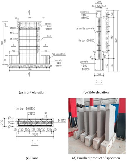
Figure 1.
Double-row reinforced ceramsite concrete sandwich composite wallboard. Notes: The unit of length is mm. C8@200 represents HRB335 stirrups with a diameter of 8 mm, and the spacing is 200 mm. C8@150 represents HRB335 stirrups with a diameter of 8 mm, and the spacing is 150 mm. 6C14 indicates six HRB400 rebars with a diameter of 14 mm; 8C12 indicates eight HRB400 rebars with a diameter of 12 mm; 4C20 indicates four HRB400 rebars with a diameter of 20 mm.
2. Experimental Design
2.1. Specimen Design
In this study, five types of wall panel specimens were designed in total, as shown in Table 1. Each specimen consisted of four types of sandwich composite wall panels and one type of solid core composite wall panel. This control group was used to analyze the effect of an insulation board on the seismic performance of composite wall panels. In addition, four types of sandwich wall panels were separated into two groups. The first group consisted of a ceramic concrete sandwich wall panel and an ordinary concrete with the strength grade of a C30 sandwich wall panel. This group was used to discuss the effect of different concrete materials on the performance of the composite wall panels. Ceramsite concrete is one of the most commonly used environmentally friendly materials. It is a lightweight type of concrete, and it has been shown to have good seismic performance. The ceramsite concrete in this group was made from ordinary concrete with a strength grade of C30 by replacing 15% of the volume of crushed stone. The design mix of the ceramsite concrete is shown in Table 2. The other set consisted of two ceramsite concrete sandwich wall panels with different mix ratios. The volume content of alkali-resistant glass fiber in the ceramsite concrete was 0.3% and 0.4%. This group was used to discuss the effect of fibers on the performance of the sandwich composite wallboard. The fibers were selected as alkali-resistant glass fibers []. The specific parameters are given in Table 3. All five test specimens consisted of three parts: the loading beam, composite wall panel core component, and foundation beam. The dimensions of the core components of the four sandwich wall panels were 1500 mm (height) × 1000 mm (width) × 200 mm (thickness), and the specific construction and the dimensions of the wall panel are shown in Figure 2. The ratio of the axial compression stress to the strength for the test was 0.1. The strength grade of the horizontal and vertical distribution steel was HRB400.

Table 1.
Parameters of the specimens.

Table 2.
Mix proportion of ceramsite concrete.

Table 3.
Parameters of alkali-resistant glass fiber.
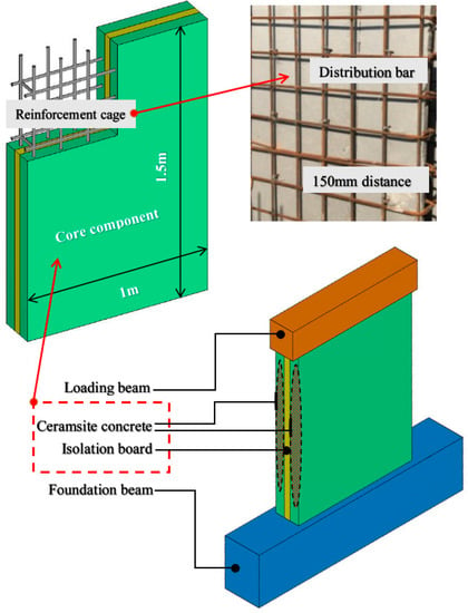
Figure 2.
Schematic diagram of three-dimensional model of specimen.
2.2. Material Performance Test
During the production of the specimens, standard test cubes (100 mm) in the same batch were reserved, totaling twelve test cubes for four materials. The test cubes were cured for 28 days under standard curing conditions before the compression test. Finally, the compressive strength of the material was regarded as the average of each group. The compressive strengths of the ceramsite concrete after adding 0.3% volume fiber ceramsite concrete, after adding 0.4% volume fiber ceramsite concrete, and for ordinary concrete were 30.6 MPa, 32.2 MPa, 31.5 MPa, and 37.8 MPa.
2.3. Loading Scheme and Measuring Point Arrangement
With reference to the “Regulations on Seismic Test Methods for Buildings (JGJ/T 101-2015)” [], the vertical loading device was first loaded to 40–60% of the design value, and then gradually loaded to 100%. The vertical loading value was kept constant during a cyclic loading test. The horizontal loading was controlled by displacement, and cyclic loading was performed according to the loading curve. The loading curve is given in Figure 3. In summary, before the specimen yielded, each level was loaded once, and after the specimen yielded, each level was cyclically loaded three times. When the specimen load dropped below 85% of the peak load, the test was completed []. The test setup is shown in Figure 4.
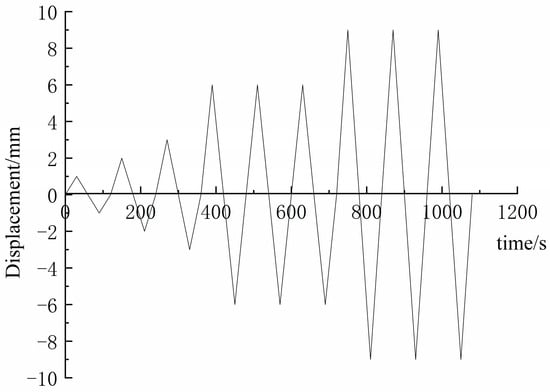
Figure 3.
Loading curve
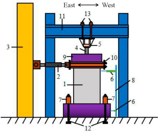
Figure 4.
Loading device. Notes: 1. Wall panel specimens; 2. Actuator; 3. Reaction wall; 4. Hydraulic jack; 5. Sensor; 6. Displacement gauge; 7. Reaction beam; 8. Upright stanchion; 9. Rigid strut beam; 10. The pull rod connection device; 11. Positive electrode method; 12. Anchor bolt; 13. Set bolt.
The main measurement items and the arrangement of measurement points are shown in Table 4.

Table 4.
The main measurement items.
Table 4.
The main measurement items.
| Item | Measurement Points | Arrangement and Means for Measuring Points |
|---|---|---|
| Overall deformation | Lateral displacement of wallboard | Displacement meter arranged along the length direction of the specimen section |
| Relative displacement between top and bottom of wallboard | Displacement meter arranged along top and bottom of high centerline of wall | |
| Local distortion | Fracture characteristics and width | Manual observation |
| Strain of distributed reinforcement and ceramsite concrete | Strain gauge measurement. For the measuring point arrangement, see Figure 5 and Figure 6 | |
| Load | Cracking, yield, and ultimate load | Sensor measurement connected with loader |
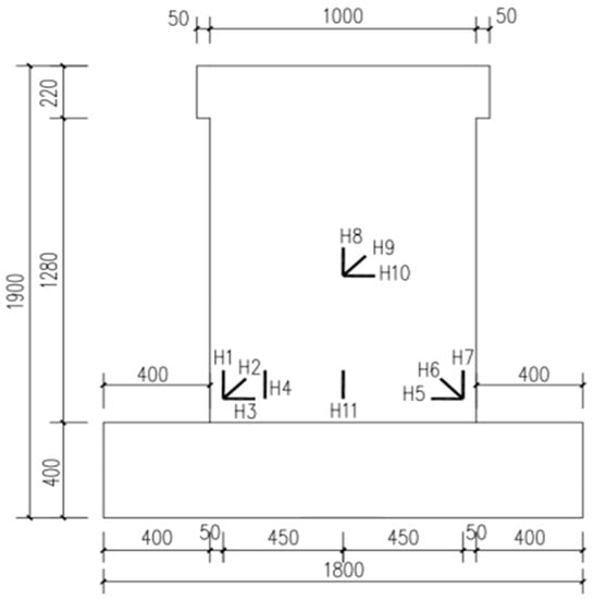
The strain gauge numbers were A1–A19, and these strain gauges were used to monitor the yield of the edge reinforcement. The specific location is shown in Figure 5. The strain gauge numbers for the concrete were H1–H11, and a vertical strain gauge was pasted at the center of the lower edge of the north wall plate. The conductor of the southern steel bar strain gauge was connected to the strain gauge outward through the lower central position, so this strain gauge was pasted on the northern wall plate.
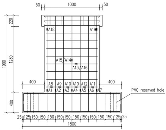
Figure 5.
Layout diagram of steel strain gauge.
3. Experimental Results and Analysis
3.1. Failure Mode of Specimen
After the surface stripped concrete was treated, the damage characteristics of the five specimens were noted. The failure characteristic diagram of the specimens are shown in Figure 7. The following patterns could be found: (1) At the time of damage, due to the different ranges of the plastic hinge, the corners of the specimens all showed different degrees of crushing and spalling. (2) The W-1, W-2, and W-3 specimens were mainly damaged by bending. The W-4 specimen was mainly damaged by shearing. This difference indicated that for the same size and reinforcement, the choice of ceramic concrete as the load-bearing layer material for the sandwich wall panels is more in line with the seismic design requirements. (3) Compared with the damage to the W-4 specimens, the cracks formed during the damage to the W-1 specimens were denser. Additionally, the crack distribution during the damage to the W-2 specimens with additional fiber was more obvious. This indicated that the wall slab had a better ability to absorb and dissipate the seismic energy when ceramic concrete was used as the structural layer material. (4) The W-5 specimens had the phenomenon of concrete protective layer spalling at the lower abdomen position. The shear damage was more severe. In addition, a comparison of the cracking of the specimen W-5 with the remaining four sandwich wall panels revealed that the sandwich wall panels cracked earlier. Furthermore, additional fibers could improve the premature cracking of the ceramic concrete sandwich wall panels. By comparing the test results of specimen W-1 with W-2 and W-3, it could be seen that the additional fiber volume admixtures of 0.3% and 0.4% could increase the cracking displacement by 42.1% and 36.8%, respectively.
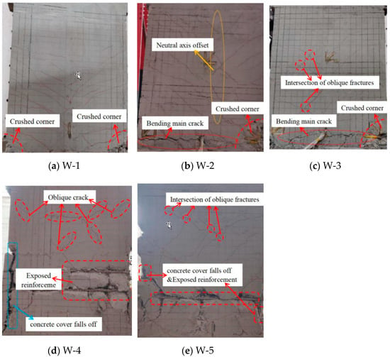
Figure 7.
Failure characteristic diagram of composite wallboard.
3.2. Hysteresis Loop
By observing the hysteresis curves of the five specimens in Figure 8, it can be seen that all five specimens were pinched together in an inverse S-shape. In the elastic stage, the hysteresis curves of the specimens plus and minus the hysteresis curves basically overlapped. The hysteresis ring enclosed a small increase in area from the specimen cracking to the gradual yielding stage. The residual deformation was small. With the increasing loading displacement and the damage accumulation, the area of the hysteresis loop gradually increased. The energy dissipation of the specimen increased accordingly.
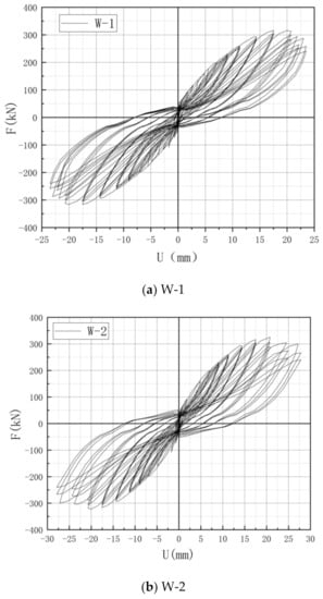
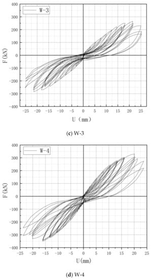
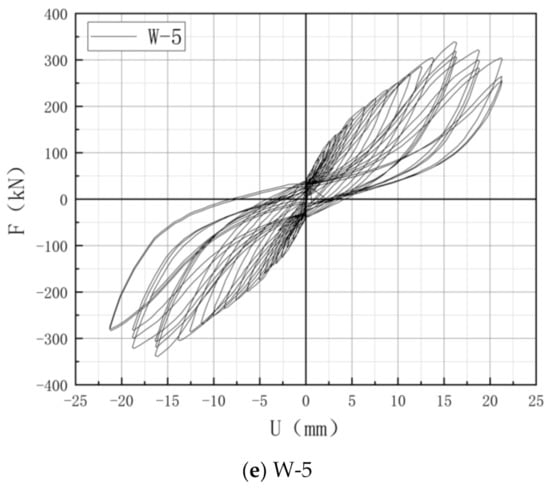
Figure 8.
Hysteresis loops of specimens.
In comparison, W-5 was a solid wall, and the integrity was better compared with the remaining four sandwich wall panels. By comparing the hysteresis curves of specimens W-1 and W-5, it could be found that the hysteresis phenomenon of the W-1 recovering deformation was not obvious. This phenomenon indicated that the uneven force in the sandwich wall panel ensured that the steel reinforcement did not play a full role.
The load-bearing materials selected for W-1 and W-4 were different. According to a comparison of the hysteresis curves of the two specimens, the difference was the instance of the load of W-4 decreasing faster after the peak load. This indicated that the ductility of W-1 was better based on the design scheme of the sandwich wall panel studied in this project.
Finally, the hysteresis curves of W-1 were compared with those of W-2 and W-3. W-2 showed a significant recovery deformation hysteresis. The result indicated that the addition of fibers could alleviate the problem of poor integrity caused by the sandwich core. Additionally, it was conducive to the establishment of force transfer paths and the energy dissipation capacity of the wall panel. In contrast, although the hysteresis curve of W-3 showed a more obvious inflection point, its hysteresis loop area was reduced, and the overall trend was more biased toward the displacement axis with a larger slip. This phenomenon indicated that fiber agglomeration was easily caused when the fiber doping was higher. This, in turn, caused a decrease in the load-bearing capacity.
3.3. Skeleton Curve
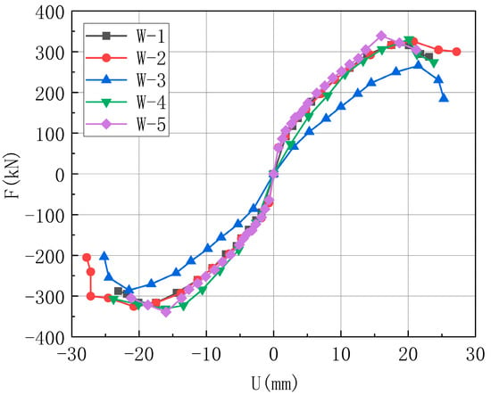
Figure 9.
Skeleton curves of specimens.
(1) The ultimate load-carrying capacity of specimen W-5 is the strongest and reaches the peak load first. The ultimate load-carrying capacity of specimen W-3 is the smallest.
(2) The ultimate displacement of specimen W-2 is the largest and the falling section is gentler, which has better ductility and best meets the design requirements of structural seismic resistance.
(3) Comparing the skeleton curves of W-1 and W-2, the deformation capacity and load-carrying capacity of the specimen were improved after adding 0.3% volume doping of fibers. But, comparing the skeleton curves of W-1 and W-3, the deformation capacity and load-carrying capacity of the members were decreased after adding 0.4% volume doping of fibers.
3.4. Bearing Capacity and Deformation Analysis
The test results for each specimen characteristic point are shown in Table 5. The yield load and the yield displacement were determined with the energy equivalent method. (1) After a comparison of the test results of W-1 and W-5, it was observed that the bearing capacity of each stage decreased. The ultimate bearing capacity decreased the most obviously, and the ultimate bearing capacity of W-1 decreased by 7.1%. (2) After a comparison of the test results of W-1 and W-4, it was observed that the cracking load of W-1 increased by 22.6%, and the yield load increased by 1%, but the ultimate load decreased by 4.5%. It could be seen that the selection of ceramsite concrete could improve the premature cracking of the wall slab, but this would compromise the load-bearing capacity of the wall slab. (3) The cracking, yielding, and ultimate loads of specimen W-2 were compared with those of W-1. The loads of W-2 were increased by 22.2%, 7.8%, and 3.2%, and the corresponding displacements were increased by 42.1%, 16.9%, and 18.3%, respectively. This result suggested that the addition of fibers was more effective in retarding cracking, and the plastic deformation capacity of the wall panel was improved after the yielding of the specimens. In contrast, the cracking, yielding, and ultimate load were reduced by 29%, 31.3%, and 15.7%, respectively, and the corresponding displacements were increased by 26.9%, 7%, and 1.3%, respectively, for W-1 compared with W-3. This indicated that the deformation capacity of the wall panel was stronger. However, the stiffness is smaller when the fiber admixture was 0.4%, which led to a substantial decrease in the load-carrying capacity of the wall panel.

Table 5.
Test result.
3.5. Ductility Analysis
The ductility coefficient was used as a parameter to measure the ductility to facilitate the observation of the final deformation capacity of each specimen under seismic loading, and the calculation Equation (1) was as follows []:
Notes: μd—the ductility coefficient.
The W-1 specimen was used as the control group. The ductility coefficients of the five specimens were compared, as shown in Table 5. (1) W-2 had the best ductility and W-3 had the second-best ductility. This implied that the fiber volume doping amount within 0.4% could improve the ductility of the members and enhance the plastic deformation ability of the members. (2) The ductility coefficient of W-5 was the smallest, which indicated that the ductility of the sandwich wall panel was better. (3) The ductility coefficient of W-1 was higher than that of W-4, which indicated that the use of ceramic concrete as the load-bearing material could improve the ductility of the wall panels.
3.6. Energy Consumption Analysis
In this study, the seismic performance of five specimens was mainly evaluated using the energy dissipation coefficient. The specific results are listed in Table 4. The calculation diagram is shown in Figure 10. The sketch of the calculation of the energy dissipation coefficient and Equation (2) is as follows [].
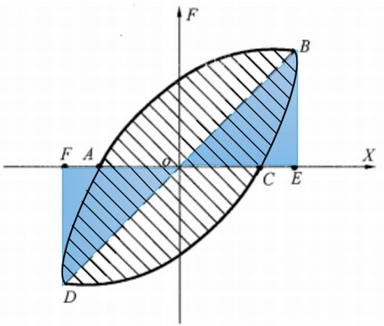
Figure 10.
Computational diagram of the energy dissipation coefficient.
A W-1 specimen was used as the control group. The energy dissipation coefficients of the five specimens were compared, as shown in Table 5. The observations in Table 5 show that the energy dissipation coefficient of the W-2 specimen was the largest and that of W-3 was the smallest. With the increase of the fiber doping, the energy dissipation capacity of the wall panel roughly showed the trend of first increasing and then decreasing. The incremental results of W-1, W-4, and W-5 indicated that the sandwich wall panels had a relatively exceptional heat dissipation capability.
3.7. Rigidity Degeneration
The stiffness degradation of the specimens was evaluated using the cut-line stiffness []. Figure 11 shows a comparison of the stiffness degradation of the five specimens. Firstly, the initial stiffness of W-5 was the largest. Secondly, the degradation curves of the four sandwich wall panels had no obvious inflection point before and after yielding. Finally, the initial stiffness of the W-2 specimen increased compared to W-1, and after cracking, the rate of stiffness degradation became slower. In contrast, specimen W-3 not only resulted in lower initial stiffness than that of specimen W-1 due to excessive fiber incorporation, but also the degradation of wall panel stiffness was more obvious.
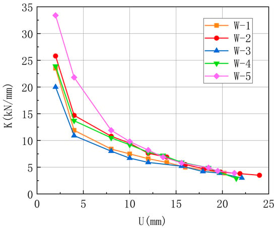
Figure 11.
Comparison chart of stiffness degradation.
3.8. Strain Analysis
By processing the strains of the reinforcement bars numbered A1 to A4, the specific strain changes of the vertical distribution bars of the wall slab could be observed, as shown in Figure 12 below.
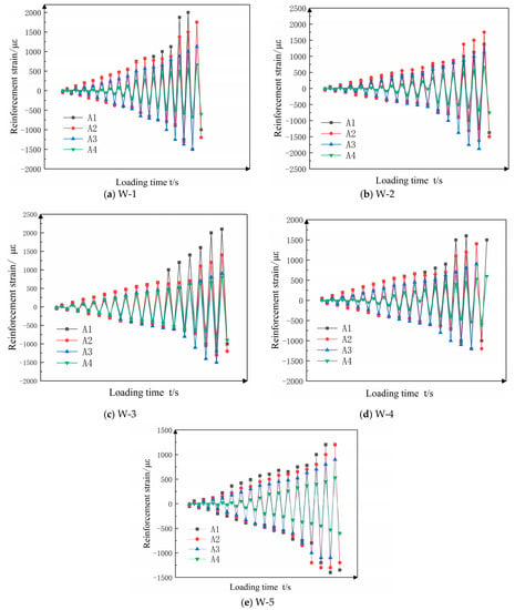
Figure 12.
Longitudinal strain diagram.
(1) The strains of specimen W-1 remained essentially the same as those of A2 in the early stage of stressing, A3 had the second largest values, and A4 was located on the central axis with the smallest strain. In the later period, A1 bore more tension and the strain increased, while A3 bore more pressure and the negative strain increased, indicating that the specimen was shifted westward in the neutral axis in the later period of loading, which made the area of the pressure zone decrease and the tension zone increase for the positive loading. The opposite occurred for the negative loading. The observation of the maximum strain value could also be found in that only A1 yielded in tension, indicating that the westward offset of the neutral axis in the late stage of loading caused the difference in the force situation between the east and west sides of the wall plate, so the strain of A1 in compression was less than that of A3.
(2) The W-2 specimen kept the maximum strain of A2 for both positive and negative loading in the early stage, and the maximum strain of A2 in tension in the late stage. A1 started to take effect and the strain gradually increased, and the specimen had the maximum strain of A3 in compression. This meant that W-2 also had the situation of neutralizing the axial westward movement. Additionally, observation of the maximum strain value could be found regardless of the fact that the tensile and compressive tendons had not yielded. After the concrete was crushed, the compressive longitudinal tendons still had not yielded, indicating that the utilization rate of the longitudinal distribution tendons was not ideal. While the strain patterns of the reinforcement in specimens W-3 and W-4 were similar to those in W-1, A1 in specimen W-3 also yielded in tension, while W-4 was similar to W-2 in that it yielded in both tension and compression. This indicated that the higher the strength of the wall panel was, the lower the utilization of the steel reinforcement was for the height to width ratio as well as the reinforcement scheme designed in this study.
(3) W-5, as a solid wall panel, was more uniformly stressed, and it essentially maintains the rule that the strain of the longitudinal bars decreased from the outside to the inside and the strain of the outermost longitudinal bars was the largest, but the maximum strain of W-5 did not reach the yield strain due to the limitation of the height-width ratio.
The valid data before the failure of the concrete strain gauges were selected and the strain curves of the reinforcement-concrete were plotted, as shown below, by specifically observing the synergy of each specimen. Firstly, when comparing Figure 13a with Figure 13e, it was obvious that the fitted length of the two materials was significantly shortened after adding the insulation board, which more intuitively indicated that the sandwich wall panels were less able to work together. Secondly, Figure 13a–c shows that the integrity of the W-2 specimen was significantly improved, while the change of W-3 was not significant, indicating that the fiber doping of 0.3% was more beneficial for improving the integrity of the specimens than the fiber doping of 0.4%. Finally, the difference between the fitted lengths of W-4 and W-1 was not significant, which indicated that the two load-bearing materials selected in this research had less influence on the integrity of the test wall panels.
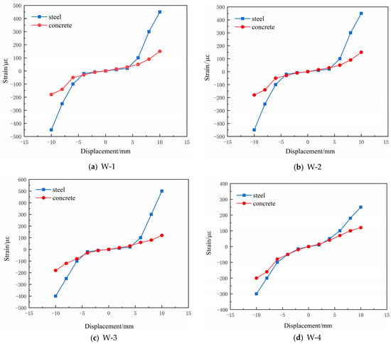
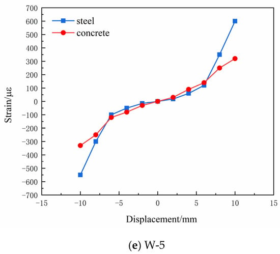
Figure 13.
Steel-concrete strain diagram.
4. Conclusions
In this paper, a new type of double-row reinforced ceramsite concrete energy-saving composite wall panel was proposed by changing the thickness of the structural layer of the wall panel, material properties, and the form of reinforcement. Its seismic performance was studied. The main conclusions are as follows:
- This paper proposes a new type of sandwich composite wall panel with an integrated insulation system and wall panel structure, whose unique construction form can not only block a fire source and avoid a fire but also easily solve the common problem of the easy shedding of insulation materials in engineering, which has a good prospect for engineering applications.
- The new sandwich composite wall panel adopted double rows of reinforcement, and the connection method adopted straight inserted reinforcement. Tie-bar connectors could effectively fix the insulation board, improve the overall force and deformation performance of the composite wall panel, and increase the ductility and energy dissipation capacity of the members. Furthermore, the test results showed that the seismic comprehensive index of the members could be effectively improved by optimizing the structure layer thickness, material type, and reinforcement of the wall panels.
- The use of ceramsite concrete instead of plain concrete as the panel material with the same size resulted in a slight reduction in the load-bearing capacity, but significant advantages in terms of the energy dissipation capacity and ductility. The new sandwich composite wall panel′s self-weight was reduced by about 20% compared with the composite wall panel without an insulation board of the same size, which was conducive to enhancing the seismic performance of the overall structure of the wall panel.
- To improve the bearing capacity of the new wall panel, the additional fiber in the vitrified concrete was a proven method. Compared with W-1 (specimens without the addition of fiber) in terms of cracking and yielding to the ultimate load, the results for W-2 (specimens with 0.3% fiber volume admixture) increased by 22.2%, 7.8%, and 3.2%. This phenomenon indicated that the addition of fibers could effectively retard the cracking of the wall panels. In addition, adding the right amount of fiber could improve the load-bearing capacity and energy dissipation capacity of the wall panel to a certain extent, and improve the comprehensive mechanical index of the sandwich wall panel. However, the addition of too many fibers was counterproductive. In the subsequent optimization design of a wall panel, the type of fiber and the amount of fiber incorporation can be studied more deeply.
- According to the law of stiffness degradation and the law of force deformation of vertically distributed reinforcement, it could be concluded that the degradation trend of the double-row reinforced ceramsite concrete sandwich composite wall slab was relatively gentle, and the components of the wall slab worked well together. The wall slab with ceramic concrete material had a discounted stiffness compared with that of ordinary concrete material. The results of this study showed that when the fiber admixture was 0.3%, the problem of the stiffness reduction of the wall panel could be effectively solved. The same conclusion could be drawn from the material strain analysis. The double-row reinforced ceramsite concrete sandwich composite wall panel could give full play to the advantages of each constituent material and work synergistically to share the force.
Author Contributions
S.M. performed the tests, analyzed the data and wrote the paper. L.L. and P.B. conceived and supervised the work. All authors contributed to conclusion of the thesis. All authors have read and agreed to the published version of the manuscript.
Funding
The authors would like to express heartfelt gratitude to the financial support by the Science Technology of the Ministry of Housing and Urban-Rural Development (No. 2018-K9-065), China Postdoctoral Science Foundation funded project (No. 2018M632805), Key scientific and technological project of Henan Province (No. 212102310932), Key scientific and technological project of Kaifeng City (No. 2001010).
Institutional Review Board Statement
Not applicable.
Informed Consent Statement
Not applicable.
Data Availability Statement
Not applicable.
Conflicts of Interest
The authors declare no conflict of interest.
References
- Lu, J.; Wang, D.H.; Zhao, K.; Liu, S.Y. Experimental performance of intermittent space heating with different terminals in a self-thermal insulation building. J. Zhejiang Univ. Eng. Sci. 2020, 54, 2092–2099, 2108. [Google Scholar]
- Tsinghua University Building Energy Conservation Research Center. Research Report on Annual Development of Building Energy Efficiency in China; Chinese Building Industry Press: Beijing, China, 2018. [Google Scholar]
- Nie, J.Z.; Liu, J.L.; Li, D.Y.; Feng, S. Analysis of factors affecting energy consumption of typical residential buildings in northern new countryside based on energy consumption simulation. J. New Build. Mater. 2020, 47, 139–146. [Google Scholar]
- Brown, J.R.; Li, M.; Palermo, A.; Pampanin, S.; Sarti, F. Experimental testing of a low-damage post-tensioned C-shaped CLT core-wall. Struct. Eng. 2020, 147, 04020357. [Google Scholar] [CrossRef]
- Salmon, D.C.; Einea, A.; Tadros, M.K.; Culp, T.D. Full scale testing of precast concrete sandwich panels. Aci Struct. J. 1997, 94, 354–362. [Google Scholar]
- Memon, N.A.; Sumadi, S.R.; Ramli, M. Ferrocement encased lightweight aerated concrete: A novel approach to produce sandwich composite. Mater. Lett. 2007, 61, 4035–4038. [Google Scholar] [CrossRef]
- Ng, S.C.; Low, K.S. Thermal conductivity of newspaper sandwiched aerated lightweight concrete panel. Energy Build. 2010, 42, 2452–2456. [Google Scholar] [CrossRef]
- Qiu, J.; Xing, M.; Yang, Z.; Zhang, C.; Guan, X. Micro-pore structure characteristics and macro-mechanical properties of PP fibre reinforced coal gangue ceramsite concrete. J. Build. Eng. 2020, 2020, 1192–1197. [Google Scholar]
- Li, X.G.; Yan, F.J.; Yue, X.T.; Wang, X.G. Research progress of ceramsite concrete. Bull. Chin. Ceram. Soc. 2020, 39, 3407–3418, 3452. [Google Scholar]
- Xie, J.; Zhao, J.; Wang, J.; Huang, P.; Liu, J. Investigation of the high-temperature resistance of sludge ceramsite concrete with recycled fine aggregates and GGBS and its application in hollow blocks. J. Build. Eng. 2020, 34, 101954. [Google Scholar] [CrossRef]
- Bi, X.X.; Yu, Y.; Li, Y.; Zhang, Z.J.; Lv, F.L. Experimental study on deformation and failure characteristics of ceramsite concrete block under typical loading mode after freeze-thaw cycles. J. New Build. Mater. 2021, 48, 103–106. [Google Scholar]
- Chen, Y.M. Experimental Research on the Mechanical Properties of Ceramsite Concrete Core Self-Insulation Wallboard. Master’s Thesis, Henan University, Kaifeng, China, 2016. [Google Scholar]
- Geng, Z.H. Analysis of Ceramsite Concrete Insulation Sandwich Wall under Low Cyclic Loading. Master’s Thesis, Henan University, Kaifeng, China, 2016. [Google Scholar]
- Bao, P.; Ma, S.C.; Han, X.X.; Zhong, S.; Fu, H.; Yue, J. Performance analysis of ceramsite concrete sandwich insulation composite wallboard. J. Henan Univ. Nat. Sci. 2017, 47, 591–596. [Google Scholar]
- Cavaleri, L.; Di Trapani, F. Cyclic response of masonry infilled RC frames: Experimental results and simplified modeling. Soil Dyn. Earthq. Eng. 2014, 65, 224–242. [Google Scholar] [CrossRef]
- Celarec, D.; Dolšek, M. Practice-oriented probabilistic seismic performance assessment of infilled frames with consideration of shear failure of columns. Earthq. Eng. Struct. Dyn. 2013, 42, 1339–1360. [Google Scholar] [CrossRef]
- Ferraioli, M.; Lavino, A. Irregularity effects of masonry infills on nonlinear seismic behaviour of RC buildings. Math. Probl. Eng. 2020. [Google Scholar] [CrossRef]
- Yuen, Y.P.; Kuang, J.S. Nonlinear seismic responses and lateral force transfer mechanisms of RC frames with different infill configurations. Eng. Struct. 2015, 91, 125–140. [Google Scholar] [CrossRef]
- Ma, S.C.; Bao, P.; Jiang, N. Experimental study of gypsum-concrete dense-column composite boards with external thermal insulation systems. Appl. Sci. 2020, 10, 1976. [Google Scholar] [CrossRef]
- Ma, S.C.; Jang, N. Experimental investigation on the seismic behavior of a new-type composite interior wallboard. Mater. Struct. 2016, 49, 5085–5095. [Google Scholar] [CrossRef]
- Darzi, S.; Karampour, H.; Bailleres, H.; Gilbert, B.P.; Fernando, D. Load bearing sandwich timber walls with plywood faces and bamboo core. Structures 2020, 27, 2437–2450. [Google Scholar] [CrossRef]
- Mehran, Z.; Ronagh, H.R. Seismic performance of cold formed steel walls sheathed by fibre-cement board panels. J. Constr. Steel Res. 2015, 107, 1–11. [Google Scholar]
- Polastri, A.; Izzi, M.; Pozza, L.; Loss, C.; Smith, I. Seismic analysis of multi-storey timber buildings braced with a CLT core and perimeter shear-walls. Bull. Earthq. Eng. 2019, 17, 1009–1028. [Google Scholar] [CrossRef]
- Pohoryles, D.A.; Maduta, C.; Bournasa, D.A.; Kouris, L.A. Energy performance of existing residential buildings in Europe: A novel approach combining energy with seismic retrofitting. Energy Build. 2020, 223, 110024. [Google Scholar] [CrossRef]
- Ma, S.C.; Jia, P.J.; Bao, P.; Yuan, Q.M. Experimental analysis on mechanical properties of alkali resistant glass fiber reinforced ceramsite concrete. China Concr. Cem. Prod. 2020, 12, 45–49. [Google Scholar]
- JGJ/T101-2015 Specification of Seismic Test of Buildings; Chinese Building Industry Press: Beijing, China, 2015.
- JGJ101-96 Specification of Testing Methods for Earthquake Resistant Building; Chinese Building Industry Press: Beijing, China, 1997.
- Ma, S.C.; Iang, N. Seismic experimental study on new-type composite exterior wallboard with integrated structural function and insulation. Materials 2015, 8, 3732–3753. [Google Scholar] [CrossRef]
- Ma, S.C.; Fang, H.Y.; Bao, P.; Jiang, X.L. The influence rule of horizontal steel bar connection on seismic behavior of assembled composite shear wall joints. J. Struct. Eng. 2020, 11, 1–8. [Google Scholar] [CrossRef]
- Javadi, M.; Hassanli, R.; Rahman, M.; Karim, R. Experimental study on cyclic behavior of post-tensioned segmental retaining walls (PSRWs). Eng. Struct. 2020, 229, 111619. [Google Scholar] [CrossRef]
Publisher’s Note: MDPI stays neutral with regard to jurisdictional claims in published maps and institutional affiliations. |
© 2021 by the authors. Licensee MDPI, Basel, Switzerland. This article is an open access article distributed under the terms and conditions of the Creative Commons Attribution (CC BY) license (http://creativecommons.org/licenses/by/4.0/).
