Abstract
Current pallet design methodology frequently underestimates the load capacity of the pallet by assuming the payload is uniformly distributed and flexible. By considering the effect of payload characteristics and their interactions during pallet design, the structure of the pallets can be optimized, and raw material consumption reduced. The objective of this study was to develop and validate a finite element model capable of simulating the bending of a generic pallet while supporting a payload made of corrugated boxes and stored on a warehouse load beam rack. The model was generalized in order to maximize its applicability in unit load design. Using a two-dimensional, nonlinear, implicit dynamic model, it allowed for the evaluation of the effect of different payload configurations on the pallet bending response. The model accurately predicted the deflection of the pallet segment and the movement of the packages for a unit load segment with three or four columns of boxes supported in a warehouse rack support. Further refinement of the model would be required to predict the behavior of unit loads carrying larger boxes. The model presented provides an efficient solution to the study of the affecting factors to ultimately optimize pallet design. Such a model has not been previously developed. The model successfully acts as a tool to study and predict the load bridging performance of unit loads requiring only widely available input data, therefore providing a general solution.
1. Introduction
Consumer-packaged goods are handled and transported predominantly in unit load form, commonly using wooden pallets and corrugated fiberboard boxes [1,2]. Pallets are key throughout most supply chains, from agricultural operations to retailers [3]. The design of pallets for material handling has evolved from a trial-and-error method to the development of advanced modeling systems [4,5,6,7,8]. The need for better models is supported by the material consumption present in pallet manufacturing and by the overall resources utilized in transportation operations [9,10]. Estimates place the number of pallets in circulation at over 2 billion units in the United States and 6.8 billion units globally [3,11]. In 2016 in the United States, more than 500 million new pallets were manufactured, and 341 million were repaired for continued use. The volume of wood consumed for pallet manufacturing represented 21.8% of the total lumber production in the United States. Pallets for material handling represent one of the largest segments in consumption of sawn hardwoods in the United States, with 45% of the total production being dedicated to them [12]. A critical need exists for efficient use of the natural resources consumed to support supply chains. Proper design of each component in the system is required.
The load carrying capacity of most pallets is determined using a uniformly distributed load for each support condition of use, such as warehouse racking or floor stacking [13,14]. Research conducted as early as 1982 shows that when pallets are loaded with specific payloads, instead of uniform loads, pallet bending is reduced due to the redistribution of the stresses on the pallet towards the supports [4,15]. Further exploration of this redistribution of stress across the pallet’s top deck, known as the load bridging effect, has been conducted mostly through physical tests measuring the change in pallet deflection. The international standard, ISO 8611-Part 3 [16], recognizes the effect of load bridging by allowing for the determination of a maximum working load of a pallet for a specific payload.
Research efforts have been made to further understand which aspects of the pallet, or the payload, significantly influence load bridging for specific payload configurations. One of the first comprehensive studies was conducted in 1997. They first determined five differing levels of rigidity for a payload and then measured how much the deflection changed under each level [17]. Although a clear effect in the results was observed (deflection decreased in direct relation to the payload rigidity), the results can only be considered preliminary since the effect of individual factors were not isolated from each other. The isolated effect of multiple palletizing characteristics such as containment force [18], box size [19,20,21], flute size [19], box contents [22], and interlock stacking [23] were previously investigated. All of these studies used physical testing which involved the construction of unit loads or segments of unit loads and subsequent laboratory measurements. Physical testing of unit loads can provide valuable information but has drawbacks. Physical testing is a time-intensive endeavor, interactions between variables are hard to investigate, and the control of experimental variables is not a simple task.
Simulations using the finite element method have been used extensively in the mechanical engineering field and recently have been widely adopted in the packaging field. Research includes finite element analysis (FEA) of different packaging materials, such as wood [24], corrugated board [25,26,27,28], paperboard [29,30] and multiple others [31], including the extensive use of finite element models in the development of food packaging [27,32,33,34,35].
The use of finite element analysis has also become commonplace when designing pallets for material handling systems. Wooden pallets can be designed using commercial software that are already available; most of which are based on finite element models [36]. Multiple studies that evaluate new pallet designs with innovative materials can be found in the literature. These studies show that the application of finite element models allow for preliminary evaluations of pallet performance [37,38,39,40]. Han, White, and Hamner [41] applied the finite element method to better understand and explain the distribution of stresses on a single board of the pallet’s top deck. Weigel [42] developed a finite element model to study the resonant frequencies of unit loads of palletized apples and peaches.
The application of the finite element method to study the load bridging effect can be a cost and time efficient alternative. FEA allows researchers to analyze the effect of multiple variables and their interactions with a scope not possible in physical testing. The finite element method has not been previously utilized for the modeling of unit loads and their effects on pallet deformation. Developing a load bridging model that can support pallet and unit load design processes can help reduce design inefficiencies and optimize material consumption at large scales. Currently, such a tool does not exist and its development can help in the advancement of the packaging field towards better design and understanding of the load bridging effect.
The main objective of this investigation was to develop and validate a simplified two-dimensional finite element model that can accurately predict the deflection of a pallet analog carrying stacked boxes in a simulated warehouse storage rack.
To be able to complete this main objective, specific sub-objectives were defined.
- To develop a finite element model to predict the behavior and deflection of a simulated unit load segment.
- To validate the ability of the finite element model to accurately replicate the deflection of a unit load segment on racking support for different payload configurations.
The structure of the paper is as follows: in Section 2, a common unit load representation is described and the simplifications and assumptions for modeling are detailed. In Section 3, a two-dimensional finite element model of the unit load segment is established. All the model information for accurate replication is provided. In Section 4, the materials and methods for the experimental validation are presented. The model validation is conducted in two major steps. First, the pallet support and the board are validated, followed by the validation of the unit load segment, including multiple different payloads. In Section 5, the results of the model validation are presented. A discussion on the agreement of the physical representation and the finite element model is provided. Section 6 presents the main conclusions of the investigation.
2. Unit Load Selection and Simplification
In order to reach the goal of developing a general tool with which to study the load bridging effect in unit loads, limitations were defined. Without these limitations, any tool modeling unit loads would require extensive information and data collection, rendering the potential applications of the final model only to limited, expensive studies.
This research project limited the support conditions studied to warehouse racking across the pallet width. Previous research studies have identified this support condition as the one that most often limits the pallet load carrying capacity, given that it commonly presents the greatest pallet deformation [20,21,23]. The warehouse racking condition where the pallet is racked across its width will be referred to as simply “racking support.” Additionally, it is assumed that under this condition, as shown in Figure 1, the displacement due to the bending of the supporting pallet and box movement is primarily along the xy-plane, with negligible displacement along the z-axis. This assumption is supported by the results in a study by Molina et al. [23]. In this study, when varying the different load bridging factors, such as pallet design and package orientation, the rate of changes in pallet deflection generated were consistent for the center and the ends of the pallet, indicating that the effect of load bridging is not dependent on the location of the pallet deflection measurement. Based on the series of tests conducted by Molina et al., the bending phenomena can be accurately described by a two-dimensional model. Therefore, a single row of boxes, shown shaded in Figure 1, was modeled to represent the unit load and the payload’s interactions. The pallet geometry was simplified to be just one board, it being deep enough to support a single row of boxes. A similarly simplified unit load segment has been used for physical testing in previous studies [18,19,22]. All measurements of pallet bending were considered initial, ignoring the effects of long-term creep on the bending response.
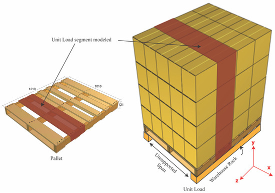
Figure 1.
Diagram of a pallet and of a unit load supported on a warehouse rack across the width. Red shaded segment represents the unit load and pallet sections modeled.
Corrugated boxes were modeled as nondeformable solid objects, subject to gravitational forces and frictional interactions. It is well-known that corrugated boxes are prone to buckling and other deformations while loading, especially the boxes located at the bottom of the stack in a unit load. While, undoubtedly, boxes with significant deformation would impact the results obtained in this study, the study is limited to unit loads carry new, undamaged packages. These packages have been properly designed to provide the required carrying capacity to support loading without significant deformation. Furthermore, the boxes used for the experimental validations contained rigid oriented strand board (OSB) containers closely fitted inside, preventing any buckling deformation from handling and loading during the experimental validation.
Box contents were not considered in this model. This simplification is supported by previously conducted research that investigated the effects of box contents on pallet deflection [22]. Even though the strength of a corrugated box can be influenced by its contents, the shape or form of the contents does not affect overall pallet deflection as long as the boxes are not deformed.
The pallet was represented in the model using a board as a pallet analog; thus, the effect of the pallet structure was not considered. Pallets can be designed in many different ways with many different materials, and some of these variations might have characteristics that affect the bending profiles. Other structural elements of pallets, such as the effect of stringers and deck boards, were also not considered. Only unit loads of boxes that provided full coverage of the pallet or pallet simulator deck were used. Under or overhanging packages on a pallet could possibly behave in a different manner. Pallet dimensions were based on the Grocery Manufacturers Association specification of 1219 mm × 1016 mm.
This model did not include the effects of additional containment mechanisms such as stretch wrapping. Containment forces increase unit load rigidity and should decrease further the pallet deflection. This should be properly validated, but the conservative approach, which produces a higher deflection, provides a reliable starting point for modeling of unit loads through the application of finite element analysis.
3. Development of a Two-Dimensional Finite Element Model of a Unit Load Segment
A two-dimensional finite element model was developed using Abaqus CAE 16, to replicate a segment of a unit load of stacked corrugated boxes on a board, as shown in Figure 2. The initial model was developed for a unit load segment of three columns with three layers of boxes and then modified to present different combinations.
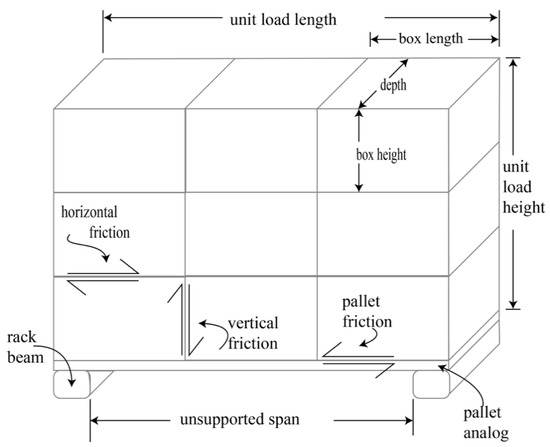
Figure 2.
Diagram of the unit load segment modeled.
3.1. FEA Material and Section Assignments
The pallet analog, or board, was modeled as a two-dimensional object with dimensions of 1016 mm along the length and a thickness of 19 mm, made out of Poly-methyl methacrylate (PMMA). Boxes were also 2D objects with dimensions 338 mm × 318 mm. A homogeneous solid section thickness of 254 mm was used for all instances as the material depth along the Z-axis. The materials utilized for the pallet analog and boxes were defined as homogeneous, isotropic, and linear elastic, specified by the Young’s modulus and Poisson’s ratio. A stiffness value high enough as to be effectively considered rigid (600 GPa) was used for the boxes or packages to simulate non-deformable objects under the loading events presented but maintaining the additional material properties of linear elastic objects. Additionally, the mass densities of the board and boxes were required, since loading was applied through gravitational acceleration. A summary of the model’s material properties is presented in Table 1. The aluminum rack beams of a warehouse rack were modeled as 2D discrete rigid objects measuring 50.8 mm × 50.8 mm with their corners rounded to a 5 mm radius in order to replicate the same contact properties experienced by the board, representing the pallet analogue, and the beams in the racking condition simulated.

Table 1.
Material properties for the unit load analogue components used for the model development.
3.2. Boundary Conditions and External Forces
Considering that the model being replicated was affected mostly by weight and not by the application of specific externally applied loads, the loading was simulated through the addition of gravitational forces along the negative Y-axis, using the standard acceleration on the surface of the Earth of 9.81 m s−2. The specification of mass density for each instance in the model was required. The finite element model was solved with a nonlinear incremental solver to account for the nonlinear mechanics associated with the frictional contact mechanics as well as the large deflections developed in the model. Racking supports, or in this case the aluminum rack beams, were fixed in place using the Abaqus encastre condition, not allowing for displacement or rotation on any axis. A summary is shown in Table 2.
Table 2.
Loading and boundary conditions used for the unit load segment model.
3.3. Contact Modeling
In order to model the contact properties of the unit load segment, the static friction coefficients between the different components were measured. The coefficient of friction was measured for each of the contacts identified (Figure 2). The frictional values for the corrugated fiberboard were measured before the was converted into boxes. All coefficient of friction values were obtained following the slide angle method from the industry standard TAPPI T-815 (2018). This test method was used to evaluate the specific material’s properties and ignore any additional variations that might be present when boxes are fully converted. Figure 2 shows the location of the contacts for the horizontal, vertical and pallet frictions. Friction coefficients were measured for each of the identified contacts and the corresponding alignment of the fluting structures. Horizontal box to box contact was measured as the contact between both boards along the machine direction. Vertical contact was measured as cross direction for both specimens. The payload contact with the pallet was evaluated with the corrugated board aligned along the machine direction, given the direction of box movement along the X-axis. Table 3 shows the coefficients of friction for each contact interaction. Experimental measurements of the coefficients of friction were replicated 10 times for each contact, reducing the commonly occurring variability in frictional forces on natural materials. Figure 3 shows the experimental test setup for the determination of the coefficients of friction of each of the identified contact interactions. For simplicity, the friction corresponding to the horizontal contact between boxes will be referred to as horizontal friction, the vertical contact between boxes as vertical friction, and the contact between the pallet and the payload simply as pallet friction. All measurements were conducted under standard laboratory conditions (50% relative humidity ± 2%; 23 ± 1 °C).
Table 3.
Coefficients of friction for each contact condition in the unit load simulator, obtained according to TAPPI T-815 [46], with an average of 10 replicates per contact interaction.
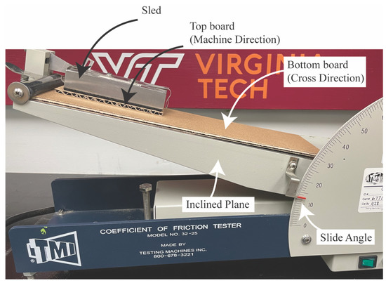
Figure 3.
Test setup for the determination of the coefficient of friction of the materials studied following the test standard TAPPI T-815 [46].
All the components were assembled together to replicate the pallet analog supporting a unit load of stacked boxes and resting on aluminum rack beams. In order to establish boundary conditions for the model and assure proper loading of the parts, surfaces were generated so every contact region could be explicitly declared. Towards this goal, all of the frictional contacts were created in the initial step and propagated to the subsequent loading steps. Every contact interaction was defined with friction properties and with tangential behavior using the penalty friction formulation. The normal behavior for the frictional contacts was determined using a penalty function as the constraint enforcement method. This was done to allow for separation of the components after contact was established. Small sliding was permitted in the formulation of the model to represent the small relative motions expected between boxes and between the boxes and the pallet analog. Each contact interaction was defined as a surface-to-surface contact with a node-to-surface discretization method. The unit load with three columns and three layers included two frictional contact interactions for the pallet analog with the rack beams, three contacts between the top deck of the pallet analog and the bottom of the three boxes at the bottom layer, 6 contacts between the vertical edges of the boxes and six contacts for the horizontal edges of the boxes, for a total of 20 defined contact areas.
3.4. Model Discretization
Meshing was assigned individually to each object in the model. The pallet analog was discretized using the Abaqus CPE4I element type, which includes incompatible deformation modes, to include additional degrees of freedom in order to capture the bending kinematics more accurately. The quadrilateral elements for the pallet segment were sized at 2.54 mm, with a total of 3200 elements.
In order to arrive at the optimal number of elements for the pallet analog, a mesh convergence study was conducted for a unit load consisting of three columns of three layers of boxes. The goal was to select the ideal seed size for each mesh element that would converge the results into a stable value without unnecessarily increasing the number of equations needing to be solved. An element size of 2.54 mm provided that ideal size. Coarser meshes associated with larger elements reduced calculation time but impacted the deflection results. Finer meshes defined by smaller element sizes provided solutions with almost the same values but increased exponentially the computing requirements. When decreasing the element size from 2.54 mm to 1.27 mm, the resulting change was less than 1%, but it increased 2.5 times the computing requirements, generating 11,200 elements compared to 3200. The percentage difference due to change in vertical displacement was calculated by dividing the difference in vertical displacement by the vertical displacement of the previous simulation. Table 4 and Figure 4 show the summary of the results obtained from the mesh refinement and convergence studies.
Table 4.
Mesh convergence for pallet simulator for maximum deflection.
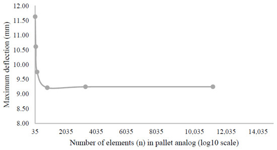
Figure 4.
Pallet simulator mesh convergence results for 3 columns, 3-layer unit load. Maximum pallet deflection (U2, mm) at the board midspan versus total number of elements.
Boxes were generated as 2D solid elements, formulated as a plane/strain linear elastic material with reduced integration, specifically the Abaqus CPE4R element. The elements were globally sized at 12.7 mm for every box, regardless of its size. To select this element size, a mesh convergence study was conducted. Figure 5 and Table 5 show the results conducted specifically for the scenario where three columns of boxes of three layers were loaded on the board. The midspan pallet analog deflection results were considered converged after the number of elements reached 6075 for the nine boxes, or when the seed size was 12.7 mm. Decreasing the box element size further, to a 5.08 mm seed, changed the results by 1.09% but increased the number of elements 6.3 times, making it unnecessarily demanding.
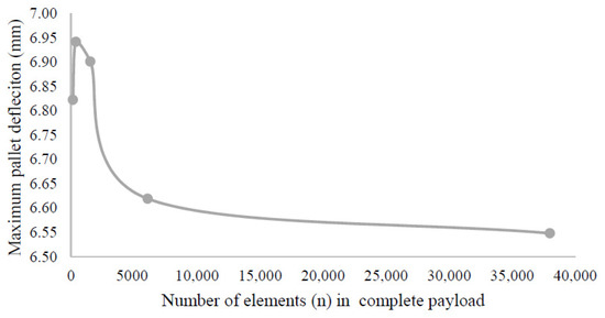
Figure 5.
Payload mesh convergence results for 3 columns, 3 layers unit load. Maximum pallet deflection (U2, mm) at the board midspan versus total number of elements.
Table 5.
Payload mesh convergence study results for 3 columns, 3 layers unit load.
The racking beam supports were discretized as 2-node, linear, discrete, rigid elements with a length of 2.54 mm and rigid link formulation, represented in Abaqus as rigid 2-noded 2D (R2D2) element. A summary of the mesh properties for each object is shown in Table 6.
Table 6.
Mesh properties for each object in the model.
3.5. Model Solver
The overall model was formulated as nonlinear, implicit dynamic. The dynamic formulation includes the representation of inertial forces into the system equations of dynamic equilibrium in order to account for the transient characteristics of the model, including the quick movements of all boxes, the large deflections experienced by the pallet analog, and all of the frictional contacts. An extended time step of five seconds was used to aid the convergence of the nonlinear contacts and deformations across the unit load segment. All deformations were considered initial board deflections, not accounting for creep effects on the structure. A summary of the model is shown in Figure 6.
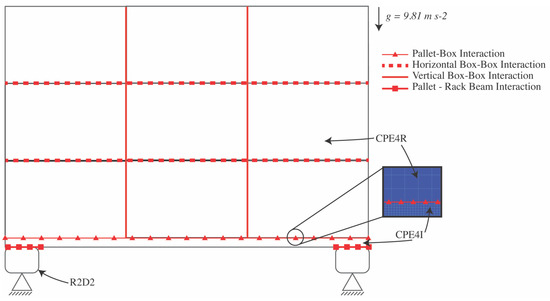
Figure 6.
Schematics of the two-dimensional finite element model with the corresponding contact interactions and mesh properties.
4. Model Validation
4.1. Materials
4.1.1. Pallet Analogue
Pallet analogues were simulated using a board of Poly-methyl methacrylate (PMMA), with dimensions of 1016 mm length, 254 mm width, and a thickness of 19 mm. PMMA is a commonly used material; its material properties are shown in Table 1. This type of board allowed researchers to conduct experiments on an isotropic material with consistently repeatable properties in order to allow for more controllable experimentation and modelling than wooden pallet segments.
4.1.2. Corrugated Boxes
Regular-slotted, container-style (RSC) corrugated boxes made of single-wall, C-flute corrugated board with 7.2 kN m−1 Edge Crush Test (ECT) value were used. More information on this corrugated board can be found in Table 7. The box sizes and weights used for the study are shown in Table 8. Each corrugated box contained a box insert made of 12.7 mm thick oriented-strand-board (OSB) built to fit tightly the inside of the corrugated boxes and avoid any box deformation from repetitive loading. Weight was added using wooden pellets inside the OSB box in order to have boxes with a consistent density of 438 kg m−3. Contact interaction properties for the boxes are shown in Table 3. The boxes were manufactured on a computerized cutting table (Esko Kongsberg XL44, Manufacturer: Esko, Miamisburg, OH, USA). Top and bottom flaps of the boxes were sealed using a 50.8 mm packaging tape (3M, Saint Paul, MN, USA).
Table 7.
Material properties of the corrugated board.
Table 8.
Weight and dimensions of boxes used for model validation.
4.2. Methods
The model validation for this research was conducted in two sequential phases. First, the experimental analog of a pallet bending while in a warehouse rack support across its width was validated. This initial step allowed the researchers to confirm the accuracy of the model in replicating the pallet analog bending, before including additional complexities from the payload’s characteristics. Second, the complete unit load segment was tested, validating the model’s ability to replicate the pallet analog’s deflection response while under the different payloads being studied.
4.2.1. Validation of the FE Simulation of a Warehouse Racking Support Analogue
In order to measure pallet deflection while under each unit load configuration, a simulated pallet rack was built. The objective of this was to validate the support model without including boxes. Two square, 50.8 mm × 50.8 mm, hollow aluminum beams acted as direct supports and the pallet simulator rested on them. A free span of 914 mm between the inside ends of the aluminum beams simulated the common warehouse racking condition where the pallet is racked across its width. The aluminum beams were placed on top of two I-beams (101 mm wide flange, 101 mm high), which were secured to a rigid, flat platen on the floor.
To record board deflection, string potentiometers were attached to the center of each side of the pallet simulator (i.e., the PMMA board). Two additional string potentiometers were connected to the racking setup in order to measure and adjust the effects of the test setup when compressed downward from loading. This method assured measurement of only the board’s deflection while eliminating any influence from external loading on the test setup.
While the pallet simulator was being loaded, it was supported from underneath using two car jacks. This was done to avoid any additional bending of the pallet during the loading of the payload. The removal of the car jack supports was done at a slow rate, manually lowering the supports until they had no further contact with the board. Maximum deflection at board midspan was recorded one minute after the supports were removed. All measurements were conducted under standard laboratory conditions (50 ± 2% Relative Humidity and 23 ± 1 °C), and every material that was used had been acclimated to those conditions for at least 72 h. Figure 7 shows the experimental test setup for the warehouse racking support simulator.
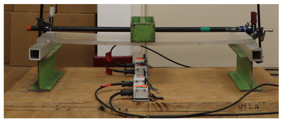
Figure 7.
Experimental test setup for a center loading with a steel weight box on the pallet simulator.
To evaluate board bending under a specific loading condition and subsequently simulate it, the PMMA pallet analogue was loaded with a steel box, as shown in Figure 7, and the absolute deflection at the center of the board was measured and recorded. Weight box dimensions were 318 mm × 114 mm × 89 mm, with a weight of 22.7 kg. The experiment was conducted five times.
4.2.2. Validation of the FE Simulation of a Unit Load Segment
Unit loads with different configurations were developed to measure the bending moment response of the pallet. Different configurations were achieved by changing the unit load’s main variables such as the number of columns, number of layers, and the total weight supported by the pallet. It is known from previous experimental research that these factors are the ones generating the main effects on load bridging [4,15,19,20,23]. Representing a wider range of unit loads during the experimental studies allows for more robust model validation afterwards. The number of layers and total weight of each unit load evaluated are shown in Table 9. Each test was replicated five times. Figure 8 shows an example of a loaded unit load segment of two columns and two layers, supported to prevent bending while under deflection. To simplify the identification of the unit loads, a notation of “columns × layers” will be used; a unit load composed of four columns and three layers will be referred as a 4 × 3 unit load.
Table 9.
Physical properties of each experimental unit with its corresponding deflection (mm) result for the experimental measurement and the finite element model simulation deflection result (mm) for each source of friction and its corresponding error.
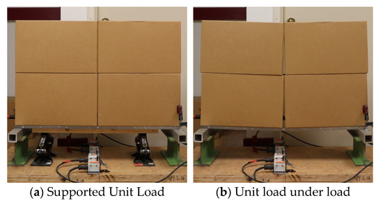
Figure 8.
Picture of unit load segment with 2 layers of large boxes, fully supported (a) and showing deflection under load (b).
4.3. Experimental Design
To conduct the validation of the finite element model of the unit load segment, each of the seven analogues studied was simulated and compared directly to the results of the experimental tests.
In order to calculate the accuracy of the model, the Mean Absolute Percent Error (MAPE) was calculated, comparing the experimental results against the finite element model results, for the seven different models. MAPE was considered to provide an accurate description of the model, given that it weighs individually each model, accounting for the differences in the absolute deflection values.
5. Results and Discussion
5.1. Warehouse Racking Simulation Results and Discussion
To validate the model without the addition of any payload complexities, the pallet segment was loaded with a steel weight box, as shown in Figure 7. The average initial deflection recorded for the plate under load was 9.40 mm with a standard deviation of 0.56 mm. To replicate this, the finite element model was modified to have only a single box matching the size of the weight box centered along the board.
For this initial validation, the main response of interest after running the simulation was the deformation of the pallet segment along the Y-axis. The largest deflection was identified at the midspan of the pallet analogue board. The predicted deflection was 9.25 mm (0.364 in). Figure 9 shows the Abaqus model results of the deformed structure. The color scheme corresponds to the deformation along the negative region of the Y-axis, with sections shaded blue as the ones with larger displacements. When compared with the experimental test measurement, the result had a deviation of −1.62%, which was deemed acceptable for the validation of the test setup and confirmed the model’s ability to accurately replicate the racking across the width pallet support test analogue.
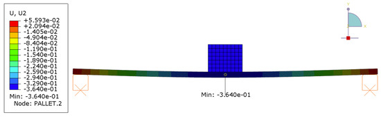
Figure 9.
Two-dimensional FE model result for the simulated pallet segment and weight box, deformed. Figure values shown in inches.
5.2. Unit Load Segment Results and Discussion
Using the support test setup that has already been validated and the methods previously described, experimental trials were conducted by loading the board with different box sizes. Small (254 × 254 × 318 mm), medium (338 × 254 × 318 mm), and large (508 × 254 × 318 mm) boxes were tested. The initial deflections recorded at the end of the simulation at the board midspan are shown in Table 9 for the seven different unit load combinations of columns and layers of boxes.
Parallel to this, the finite element model was adjusted to the same box sizes and number of layers combinations. Table 9 shows the results for each of the analyses. The mean absolute percent error (MAPE) of the model is 22%. The greatest error with 59% MAPE was observed for the unit loads with the largest boxes (two columns). By limiting the prediction scope of the model to those unit loads with three or four columns, model accuracy improves to a MAPE of 7.8%, which is considered an acceptable accuracy for such a general unit load bending model. Unit loads with three columns presented a MAPE of 12% and those with four columns a MAPE of 1.3%, suggesting an increased accuracy with smaller boxes.
The scenario of unit loads of two columns presented a special case that needs to be formulated as a different model in order to accurately predict pallet deflection. The assumptions and simplifications in this project do not properly represent the actual unit load behavior. The boxes in the designed experiment present a large ‘rotation’ movement when they are under load. This movement is accurately predicted by the model, as seen in Figure 10a. The absolute value predicted, on the other hand, diverges by 29% from the measured experimental value for the 2 × 2 unit. A similar case occurs for the unit load of 2 × 3. For this scenario, the model underpredicted the overall pallet deflection, with an error of 88%. This specific two-column scenario presented significant differences from the rest of the unit loads studied. When using the friction values obtained by evaluating the linerboard contact properties, as conducted for this study, the actual properties of the contact might not have been properly represented. Corrugated boxes have imperfections. One example could be that there was compression of the flutes or of the linerboard between the fluting structure, albeit small, but that could affect the characteristics of the horizontal box frictions or the pallet frictions. Additional variations could come from the use of packaging tape for the closures and any other environmental impurities when testing, such as dust, that could affect more directly the horizontal surfaces. When measuring the friction with the slide angle method, only the actual contact properties between the linerboards are evaluated, with low weight and perfect samples.
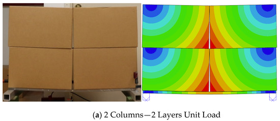
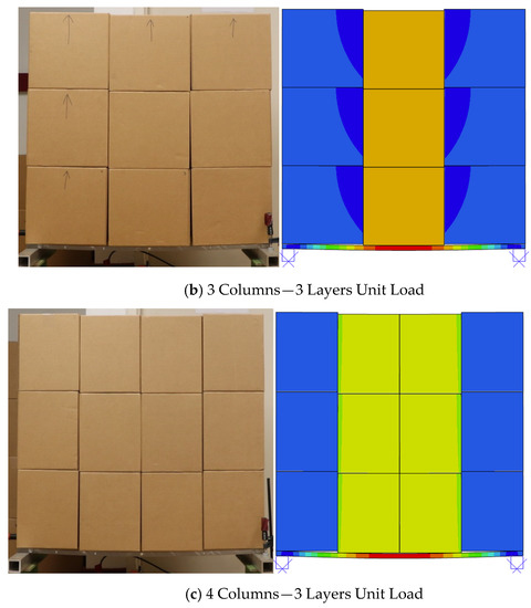
Figure 10.
Comparison of movement of unit load components under deflection for experimental (left) and finite element analysis (right) for two layers and (a) two columns, (b) three columns, and (c) four columns of packages. Images shown for the model (left) are colored based on deflection. Red equals large displacements, blue represents no movement.
Another reason for the deviation of the model with the two-column unit load can be attributed to the use of non-deformable boxes in the simulations. Unit loads with smaller boxes, such as three and four-column units, presented no deformation and therefore, they are more accurate in their prediction. The larger boxes could have slight deformations in the experimental tests, changing the contact interactions; therefore, changing how the load is transferred to the pallet and ultimately affecting the pallet’s deflection. Additionally, the use of no containment force in these experiments allowed the boxes to be freely displaced during the rotation generated through bending. This movement will be much more constrained in an actual unit load, given the use of containment mechanisms. By constraining larger displacements, the behavior of the boxes will be closer to the other scenarios, and hence could be better simulated.
For all the five scenarios where the unit loads had three or four columns, the model was capable of accurately predicting the deflection and the movement of the boxes. This movement is closely linked to their load bridging behavior. Figure 10b,c shows the behavior of the boxes in the experimental tests and in the FE simulation for the 3 × 3 and 4 × 3 units. Visually, this model reasonably replicates the box movement. The 3 × 3 unit load shows a slight box rotation at the outer columns while the center column is displaced straight downwards. Although the boxes rotate, the model is capable of accurately predicting the pallet segment’s deflection. The smaller rotation does not significantly affect the contact properties or cause any box deformation, as discussed for the two-column unit loads. The four-column unit load is also represented correctly in the model and shows high accuracy in the deflection results and in the visual inspection of box behavior. Small boxes kept their form, and the movements of these boxes were mostly along the y-axis, confirming the model’s ability to represent the load bridging accurately. The model was able to simulate a unit load’s bending accurately for three and four-column scenarios without requiring the further complexity that would be added by having to simulate corrugated panels and their potential buckling.
Being this a friction driven model, changing the pallet analogue material from the selected PMMA to a more common material such as a wooden top deck would undoubtedly change the interaction mechanics. The higher friction resistance from the wood and corrugated board interface would restrict the box’s displacement and would affect how the payload is displaced. The presented model can be extended to fully characterize this frictional effect.
Comparing the results when using a non-uniform structure to carry the payload, such as GMA pallets with stringer boards and partial top deck coverage, should not change the results of the study. This model studies the two-dimensional response on pallet bending and previous studies on load bridging using full unit loads have shown a uniform deflection response [20,21,23] that could be accurately represented as a two-dimensional model. Using materials with different stiffnesses will change the absolute deflection experienced by the board. Load bridging emphasis has been on the ratio of change from one payload to another, while maintaining the pallet, this reinforces the benefit of studying it by using a uniform pallet analogue [19].
Previous research has shed a light on the relationship between box size and how it affects pallet deflection [4,15,19,20,21,22]. The major trend in their conclusions was the evidence that as package size decreased, deflection increased. This inverse relationship has been explained by the comparing smaller packages to a more uniform load transfer from payload to the pallet, instead of the discrete loading observed for larger packages. For comparable payloads, this study mostly supports this hypothesis. The box size does affect pallet deflection, but the other identified factors can also influence the magnitude and direction of this change.
Most of the previous studies related to load bridging [4,15,19,20,21,22] conducted physical experimentations to measure the change in deflection when different payload characteristics were modified. These studies were particularly complex to conduct and validate given the multiple elements that must be controlled. The model developed here can allow for the detailed study of each one of the potentially influencing factors, such as box size, coefficients of friction, number of package layers, the stiffness of the pallets and the pallet support conditions.
The model presented here is the first attempt to validate the load bridging effect without the need for a more comprehensive and complex model. The finite element model developed can help in the study and application of the load bridging effect without the need for extensive data collection. A practical application of the model can be generated when an interested party requires the evaluation of a pallet design for multiple payloads. Current design and evaluation methodology requires for the involved party to design the pallet assuming uniform loading, which will provide the lowest possible load carrying capacity, or to study individually each one of the payloads to determine the minimum pallet carrying capacity. The presented model can help decide which payload will the pallet present the lowest carrying capacity. Pallet design can be greatly improved with this consideration. Additional studies can be conducted to fully characterize the effects of each design factor in unit loads. Knowing which factors are significant can help designers make decisions that will impact pallet carrying capacity from early on in the process. Current design practices require the development of prototypes and physical experimentation to determine how the payload configuration will affect the pallet carrying capacity. The presented tool can streamline and greatly reduce the unit load design process time and effort.
Overall, the model can simulate, with acceptable margins of error, the deflection of unit load segments and the box movements for unit loads with three and four columns of boxes. This can translate into better understanding of the load bridging effect by conducting further simulations with a wider range of variables, such as different numbers of columns, layers of boxes, payload heights, pallet stiffnesses, and all of the friction characteristics of each contact.
6. Conclusions
In this paper, a simplified, general finite element model to simulate unit load bending under warehouse load beam racking support was developed and validated. The following can be concluded:
- The two-dimensional model presented can accurately replicate the load bridging effect that has been observed in physical experimentation for unit load segments of three and four columns with an average error of 8%.
- Unit loads with very large boxes, such as a two-column unit load, present different box movement behavior when deflecting. Refinement to the model must be developed in order to study these unit loads, considering the different contact interactions, possible box deformations, and the use of additional containment methods.
- This model is capable of replicating the behavior of the multiple unit load segments when modifying payload configurations, such as changing height, weight and number of columns.
- The presented model can provide a better understanding of the load bridging effect on unit loads without the need for complex and time-intensive data collection for each model run. The model simplifications allow for it to be more widely adopted in commercial applications.
Further exploration is required to determine how each of the many variables affects pallet bending. Load bridging in unit loads has been extensively studied in physical environments. The model developed allows for the exploration of the effects and interactions which is not feasible to conduct in controlled experiments.
Author Contributions
E.M. and L.H. research conceptualization. E.M. and R.L.W. simulation model development. E.M. data collection, experimentation and writing. E.M., L.H. and R.L.W. data analysis collaboration. This research project was conducted under the supervision of L.H. All authors have read and agreed to the published version of the manuscript.
Funding
The research was financially supported by the Industrial Affiliate Program of the Center for Packaging and Unit Load Design at Virginia Tech. The corrugated boxes were donated by the Roanoke Facility of Packaging Corporations of America.
Data Availability Statement
The data presented in this study are available on request form the corresponding author.
Conflicts of Interest
The authors declare no conflict of interest.
References
- Twede, D.; Selke, S.E.; Kamdem, D.P.; Shires, D. Cartons, Crates and Corrugated Board: Handbook of Paper and Wood Packaging Technology, 2nd ed.; DEStech Publications, Inc.: Lancaster, PA, USA, 2014. [Google Scholar]
- Fibre Box Association. Fibre Box Handbook, 22nd ed.; Fibre Box Association: Elk Grove Village, IL, USA, 2015. [Google Scholar]
- McGinley, D. Wood Pallets & Skids Production in the US; IBISWorld: Melbourne, Australia, 2019. [Google Scholar]
- Fagan, B. Load-Support Conditions and Computerized Test Apparatus for Wood Pallets. Master’s Thesis, Virginia Polytechnic Institute and State University, Blacksburg, VA, USA, 1982. [Google Scholar]
- Loferski, J.R.; Mclain, T.E.; Collie, S.T. Analysis of Racked Wood Pallets. Wood Fiber Sci. 1988, 20, 304–319. [Google Scholar]
- Samarasinghe, S. Predicting Rotation Modulus for Block Pallet Joints. Master’s Thesis, Virginia Tech, Blacksburg, VA, USA, 1987. [Google Scholar]
- LeBlanc, R.; Richardson, S. Pallets: A North American Perspective, 1st ed.; PACTS Management Inc.: Cobourg, ON, Canada, 2003. [Google Scholar]
- Loferski, J.R. A Reliability Based Design Procedure for Wood Pallets. Ph.D. Dissertation, Virginia Tech, Blacksburg, VA, USA, 1985. [Google Scholar]
- Accorsi, R.; Baruffaldi, G.; Manzini, R.; Pini, C. Environmental Impacts of Reusable Transport Items: A Case Study of Pallet Pooling in a Retailer Supply Chain. Sustainability 2019, 11, 3147. [Google Scholar] [CrossRef]
- Deviatkin, I.; Khan, M.; Ernst, E.; Horttanainen, M. Wooden and Plastic Pallets: A Review of Life Cycle Assessment (LCA) Studies. Sustainability 2019, 11, 5750. [Google Scholar] [CrossRef]
- Research and Markets. Pallet Market: Global Industry Trends, Share, Size, Growth, Opportunity and Forecast 2019–2024; Research and Markets: Dublin, Ireland, 2019. [Google Scholar]
- Gerber, N.; Horvath, L.; Araman, P.; Gething, B. Investigation of New and Recovered Wood Shipping Platforms in the United States. BioResources 2020, 15, 2818–2838. [Google Scholar]
- ASTM International. ASTM D1185-98a(2009) Standard Test Methods for Pallets and Related Structures Employed in Materials Handling and Shipping; ASTM International: West Conshohocken, PA, USA, 2009. [Google Scholar]
- ISO. ISO 8611-1:2011(E) Pallets for Materials Handling—Flat Pallets; ISO: Geneva, Switzerland, 2011. [Google Scholar]
- Collie, S.T. Laboratory Verification of Pallet Design Procedures. Master’s Thesis, Virginia Polytechnic Institute and State University, Blacksburg, VA, USA, 1984. [Google Scholar]
- ISO. ISO 8611-3:2011(E) Pallets for Materials Handling—Maximum Working Loads; ISO: Geneva, Switzerland, 2011. [Google Scholar]
- Center for Unit-Load Design. The Effect of Load Bridging on Unit-Load Deflection; Center for Unit-Load Design: Blacksburg, VA, USA, 1997. [Google Scholar]
- Park, J. Investigation of Fundamental Relationships to Improve the Sustainability of Unit Loads. Ph.D. Dissertation, Virginia Polytechnic Institute and State University, Blacksburg, VA, USA, 2015. [Google Scholar]
- Park, J.; Horvath, L.; White, M.S.; Phanthanousy, S.; Araman, P.; Bush, R.J. The influence of package size and flute type of corrugated boxes on load bridging in unit loads. Packag. Technol. Sci. 2017, 30, 33–43. [Google Scholar] [CrossRef]
- Clayton, A.P.; Horvath, L.; Bouldin, J.; Gething, B. Investigation of the effect of column stacked corrugated boxes on load bridging using partial four-way stringer class wooden pallets. Packag. Technol. Sci. 2019, 32, 423–439. [Google Scholar] [CrossRef]
- Morrissette, S.M.; Horvath, L.; DeLack, K. Investigation into the load bridging effect for block class pallets as a function of package size and pallet stiffness. Packag. Technol. Sci. 2021, 34, 51–69. [Google Scholar] [CrossRef]
- Phanthanousy, S. The Effect of the Stiffness of Unit Load Components on Pallet Deflection and Box Compression Strength. Ph.D. Thesis, Virginia Tech, Blacksburg, VA, USA, 2017. [Google Scholar]
- Molina, E.; Horvath, L.; White, M.S. Investigation of pallet stacking pattern on unit load bridging. Packag. Technol. Sci. 2018, 31, 653–663. [Google Scholar] [CrossRef]
- Mackerle, J. Finite element analyses in wood research: A bibliography. Wood Sci. Technol. 2005, 39, 579–600. [Google Scholar] [CrossRef]
- Zhang, Z.; Qiu, T.; Song, R.; Sun, Y. Nonlinear finite element analysis of the fluted corrugated sheet in the corrugated cardboard. Adv. Mater. Sci. Eng. 2014, 2014, 654012. [Google Scholar] [CrossRef]
- Hammou, A.D.; Duong, P.T.M.; Abbès, B.; Makhlouf, M.; Guo, Y.-Q. Finite-element simulation with a homogenization model and experimental study of free drop tests of corrugated cardboard packaging. Mech. Ind. 2012, 13, 175–184. [Google Scholar] [CrossRef]
- Park, J.; Park, M.; Choi, D.S.; Jung, H.M.; Hwang, S.W. Finite Element-Based Simulation for Edgewise Compression Behavior of Corrugated Paperboard for Packaging of Agricultural Products. Appl. Sci. 2020, 10, 6716. [Google Scholar] [CrossRef]
- Park, J.; Chang, S.; Jung, H.M. Numerical Prediction of Equivalent Mechanical Properties of Corrugated Paperboard by 3D Finite Element Analysis. Appl. Sci. 2020, 10, 7973. [Google Scholar] [CrossRef]
- Nygårds, M.; Sjökvist, S.; Marin, G.; Sundström, J. Simulation and experimental verification of a drop test and compression test of a gable top package. Packag. Technol. Sci. 2019, 32, 325–333. [Google Scholar] [CrossRef]
- Zaheer, M.; Awais, M.; Rautkari, L.; Sorvari, J. Finite element analysis of paperboard package under compressional load. Procedia Manuf. 2018, 17, 1162–1170. [Google Scholar] [CrossRef]
- Wang, M.; Zhao, R.L.; Li, K.T. Application of the Behavioral Modeling Technique to Structure Optimization in Packaging Container Design. Appl. Mech. Mater. 2012, 200, 592–596. [Google Scholar] [CrossRef]
- Fadiji, T.; Coetzee, C.J.; Berry, T.M.; Ambaw, A.; Opara, U.L. The efficacy of finite element analysis (FEA) as a design tool for food packaging: A review. Biosyst. Eng. 2018, 174, 20–40. [Google Scholar] [CrossRef]
- Wei, H. Optimisation on Thermoforming of Biodegradable Poly (Lactic Acid) (PLA) by Numerical Modelling. Polymers 2021, 13, 654. [Google Scholar] [CrossRef]
- Czechowski, L.; Kmita-Fudalej, G.; Szewczyk, W. The Strength of Egg Trays under Compression: A Numerical and Experimental Study. Materials 2020, 13, 2279. [Google Scholar] [CrossRef]
- Garbowski, T.; Gajewski, T.; Grabski, J.K. Estimation of the Compressive Strength of Corrugated Cardboard Boxes with Various Openings. Energies 2020, 14, 155. [Google Scholar] [CrossRef]
- Modern Material Handling. Pallet Design and Analysis Software Tool Released; Supply Chain Management Review 2012. Available online: https://www.scmr.com/article/pallet_design_and_analysis_software_tool_released (accessed on 21 June 2019).
- Ratnam, M.M.; Lim, J.H.; Khalil, H.P.S.A. Study of three-dimensional deformation of a pallet using phase-shiff shadow moiré and finite-element analysis. Exp. Mech. 2005, 45, 9–17. [Google Scholar] [CrossRef]
- Mohammed, M.; Baig, A. Designing Novel Grooved Pallets for Industrial Application. Master’s Thesis, Cleveland State University, Cleveland, OH, USA, 2018. [Google Scholar]
- Waseem, A.; Nawaz, A.; Munir, N.; Islam, B.; Noor, S. Comparative analysis of different materials for pallet design using ANSYS. Int. J. Mech. Mechatron. Eng. 2013, 13, 26–32. [Google Scholar]
- Al-Fatlawi, A.; Jármai, K.; Kovács, G. Optimal Design of a Fiber-Reinforced Plastic Composite Sandwich Structure for the Base Plate of Aircraft Pallets in Order to Reduce Weight. Polymers 2021, 13, 834. [Google Scholar] [CrossRef]
- Han, J.; White, M.; Hamner, P. Development of a Finite Element Model of Pallet Deformation and Compressive Stresses on Packaging within Pallet Loads. J. Appl. Packag. Res. 2007, 1, 149–162. [Google Scholar]
- Weigel, T.G. Modeling the Dynamic Interactions between Wood Pallets and Corrugated Containers during Resonance. Ph.D. Dissertation, Virginia Tech, Blacksburg, VA, USA, 2001. [Google Scholar]
- ASTM. D198-15 Standard Test Methods of Static Tests of Lumber in Structural Sizes; ASTM: West Conshohocken, PA, USA, 2015. [Google Scholar]
- Altuglas International. Plexiglass General Information and Physical Properties. 2006. Available online: http://www.plexiglas.com/export/sites/plexiglas/.content/medias/downloads/sheet-docs/plexiglas-general-information-and-physical-properties.pdf (accessed on 28 May 2019).
- Gilchrist, A.C.; Suhling, J.C.; Urbanik, T.J. Nonlinear finite element modeling of corrugated board. Am. Soc. Mech. Eng. Appl. Mech. Div. AMD 1999, 231, 101–106. [Google Scholar]
- TAPPI. T 815 om-18-Coefficient of Static Friction (Slide Angle) of Packaging and Packaging Materials (Including Shipping Sack Papers, Corrugated and Solid Fiberboard) (Inclined Plane Method); TAPPI/ANSI: Peachtree Corners, GA, USA, 2018; pp. 1–6. [Google Scholar]


Publisher’s Note: MDPI stays neutral with regard to jurisdictional claims in published maps and institutional affiliations. |
© 2021 by the authors. Licensee MDPI, Basel, Switzerland. This article is an open access article distributed under the terms and conditions of the Creative Commons Attribution (CC BY) license (http://creativecommons.org/licenses/by/4.0/).