Article

Comparative Study of Aortic Wall Stress According to Geometric Parameters in Abdominal Aortic Aneurysms

1
Department of Biomedical Engineering, Graduate School, Pusan National University, Busan 49241, Korea
2
Department of Thoracic and Cardiovascular Surgery, Pusan National University School of Medicine, Medical Research Institute, Pusan National University Hospital, Busan 49241, Korea
3
Department of Convergence Medicine and Biomedical Engineering, School of Medicine, Pusan National University, and Biomedical Research Institute, Pusan National University Hospital, Busan 49241, Korea
4
Medical Research Institute, Pusan National University, Busan 49241, Korea
*
Author to whom correspondence should be addressed.
Appl. Sci. 2021, 11(7), 3195; https://doi.org/10.3390/app11073195
Submission received: 9 March 2021 / Revised: 29 March 2021 / Accepted: 31 March 2021 / Published: 2 April 2021
(This article belongs to the Special Issue Recent Developments and Emerging Trends in Biomechanics)

Abstract

:
In abdominal aortic aneurysm (AAA), the rupture of the aortic tissue is directly related to wall stress. Thus, the investigation of maximum wall stress is a necessary procedure to predict the aortic rupture in AAA. In this study, computational simulations were performed to investigate the correlation between peak wall stress (PWS) and AAA geometry. The Holzapfel model and various orientations of the collagen fibers and thicknesses of the layers of the aorta were employed in the simulation. The material constants used in the Holzapfel model were estimated from the examination and analysis of the biaxial tensile test results of the normal abdominal aorta and AAA. The aneurysm diameter, height, neck angle, and iliac angle were selected as geometric factors affecting the AAA rupture. In addition, a simulation scenario was conceived and created based on the measurement results using the computed tomography data of patients with AAA. Accordingly, the correlation between the PWS and AAA geometry was estimated.

Graphical Abstract

1. Introduction

Abdominal aortic aneurysm (AAA) is a disease in which the arteries that transport blood from the heart down through the chest and abdomen bulge or swell due to various factors. Usually, AAAs do not manifest any distinct symptoms and are only incidentally discerned during screening or tests performed for another reason. In addition, AAA rupture is frequently caused by different factors, and its prediction is critical because the mortality rate of ruptured AAAs is high. Such a rupture typically occurs when the wall stress exceeds the strength of the aortic tissue due to the pressure exerted on the aortic wall. The wall stress depends on the geometry, location, blood pressure, and characteristics of a patient’s aortic tissue.
In recent decades, studies on the risk factors of AAA have been conducted based on experimental, theoretical, and computational simulations. In these studies, a method for measuring the wall stress in AAAs using finite element analysis has been established as a more advanced approach than the existing method [1,2]. In particular, based on computed tomography (CT) image data, computational studies considering the diameter [1], symmetry [3], centerline curvature [4], rupture risk index [5,6], wall thickness [7,8,9], intraluminal thrombus (ILT) [10,11,12,13,14], calcification [15,16], and geometry of AAA [17,18,19,20] have been conducted to predict AAA rupture.
Fillinger et al. [2] obtained and analyzed the CT data of 48 patients with AAA to investigate wall stress according to the progression of the disease. Thereafter, they performed finite element analysis and found that the peak wall stress (PWS) increased as the AAA progressed. In a later work, Fillinger et al. [1] conducted a similar analysis using the CT data of 159 patients to investigate the risk of AAA rupture over time. They found that the prediction of AAA rupture according to the PWS was more reliable than that based on the aneurysm’s diameter. Giannoglou et al. [4] also investigated 39 AAA models and reported that the mean centerline curvature was an important factor in the multiple regression analysis of the correlation between the PWS and geometrical parameters. In addition, Doyle et al. [3] determined the relationship between the PWS and geometrical parameters of 15 AAA models and reported that considering AAA asymmetry was important in predicting rupture. Urrutia et al. [19] performed a statistical analysis of the correlation between the PWS and 47 indicators. They reported that seven indicators (tortuosity, ratio of maximum diameter to proximal neck diameter, outer wall surface area of aneurysm, median Gaussian curvature, maximum compactness, and mean curvature mode) could serve as surrogates for assessing the AAA. Azar et al. [20] conducted a scenario simulation to evaluate the sensitivity of wall stress to geometrical and mechanical properties. They reported that an integration of the geometrical parameter and mechanical properties into clinical decision-making was necessary.
The results of these various studies show that the behavior of aortic tissue was examined according to environmental conditions of AAA. However, confirming the behavior of the aortic wall based on the geometric parameters of the AAA was difficult. These parameters may induce stress concentrations on the structure of the aortic wall, and may lead to crack propagation in the aortic tissue.
Therefore, to resolve the foregoing, in this study, the biaxial tensile test results of normal abdominal aorta (NAA) tissue and AAA tissue were investigated, and a computational simulation of these tests was conducted. To simulate the experiment, the existing constitutive model is employed to reflect the properties of anisotropic hyperelastic materials, and the material constants of the constitutive model were derived. In addition, a scenario involving the aneurysm’s diameter, height, neck angle, and iliac angle was formulated based on the CT data of AAA patients. A series simulation of the scenario was performed, and the correlation between the geometrical parameters of AAAs and wall stress was examined.

2. Materials and Methods

2.1. Material Experiment Details and Results

In this study, the biaxial tensile tests of the aortic tissue as performed by Geest et al. and Niestrawska et al. [21,22] were carried out to consider the material properties of human aortic tissues in the simulation. Geest et al. [21] conducted biaxial tensile tests on NAA and AAA samples. The specimens were obtained as square strips (20 mm × 20 mm) parallel to the axis and circumferential orientation. They were mounted on the tester using four nylon sutures on each side and tested using a tension-controlled protocol performed with TaxialTcirc tension ratios of 1:1, 0.75:1, 1:0.75, 0.5:1, and 1:0.5 at 120 N/m, where Taxial and Tcirc are the values of tension in the axial and circumferential directions, respectively. In the experiment, a small preload (1 kPa) was applied to flatten the specimens, and preconditioning through loading and unloading cycles was implemented four times at the same tensile load, and on the fifth, data were measured. Consequently, the stress and strain correlations between NAA and AAA were derived. Niestrawska et al. [22] conducted biaxial tensile tests on 11 AAA samples. The specimens were obtained as square strips (20 mm × 20 mm) and mounted on a biaxial testing device by hooked surgical sutures; black tissue markers were applied to the surface of the specimen to measure deformation. A quasi-static stretch-driven protocol was used in the test performed with λ a x i a l λ c i r c stretch ratios of 1:1, 1:0.75, 0.75:1, 1:0.5, and 0.5:1 at a rate of 3 mm/min. In the experiment, zero strain was defined under a small preload (0.005 N); preconditioning was implemented four times with increments of 0.025 in the stretch until rupture, and on the fifth, data were measured.
In this examination step for material behavior, the results of the aforementioned experiments were used in combination, because the load conditions were not clearly presented in the experiment of Geest et al. [21], and Niestrawska et al. [22] only conducted tests on AAA samples. In particular, the ratios of the tensile stress and stretch were compared between NAA and AAA, based on the experimental results derived with a tension ratio of 1:1 in the test of Geest et al. [21]. Additionally, based on these ratios in the test of Geest et al. [21] and the test results for AAA samples in Niestrawska et al.’s experiment [22], the stress, stretch, and elasticity of NAA samples were estimated. These results were applied in the calculation step of the material parameter in the constitutive model.

2.2. Numerical Model

In this study, the numerical models proposed by Gasser et al. and Holzapfel et al. [23,24] were used to simulate the anisotropic hyperelastic material behavior. The strain energy density function applied to model the aortic wall is as follows:
U   =   C 10 I ¯ 1 3 +   k 1 2 k 2 α = 1 N { exp [ k 2 E ¯ α 2 ] 1 } ,
with
E ¯ a     κ I ¯ 1 3 + 1 3 κ I ¯ 4 α α 1 ,
where U is the strain energy per unit volume; C 10 ,   k 1 ,   k 2 ,   and   κ are the material constants for the arterial wall. N is the number of families of fibers N 3 . I ¯ 1 is the first deviatoric strain invariant. I ¯ 4 α α is the pseudo-invariants in Cauchy–Green strain and expresses the fiber direction, and α is from 1 to N .

2.3. Material Simulation Details

The failure stress and strain in the estimated data of the NAA sample and the experimental data from Niestrawska et al. [22] were used to analyze the material constant. In this study, ABAQUS, a commercial finite element analysis program, was employed to simulate the biaxial tensile test. First, to ensure the reliability of the simulation, the material constants of the model were calculated based on the stress–stretch curve according to the direction of the tissue.
A representative volume element (RVE) was utilized to carry out a biaxial tensile test of the aortic tissue. The number and size of the elements were 12 and 1 × 1 × 1 mm3, respectively, as shown in Figure 1. The element type used was C3D8RH, which is a general-purpose linear brick element with reduced integration, hourglass control, and hybrid constant pressure. The orientations of the collagen fiber in each layer were set as 3.25°, 6.91°, and 77.53° (intima, media, and adventitia), which were measured by Niestrawska et al. [22]; the thickness of intima, media, and adventitia were set as 0.25 mm, 0.53 mm and 0.26 mm, which were 21%, 53%, and 26% of the entire aortic thickness, respectively. The application of the orientation of the collagen fiber to the model is discussed in Section 2.5. The boundary conditions are as follows: UY = 0 for the plane perpendicular to the Y-axis, UZ = 0 for the plane perpendicular to the Z-axis, and UX = 0 for the plane perpendicular to the X-axis. Circumferential and axial displacements were applied to the plane perpendicular to the axis.

2.4. AAA Geometry Studies

In this study, a parameter-based model was employed to evaluate the effect of AAA’s geometric parameters on the arterial wall. The proposed parameters were measured through CT data analysis. The CT data of 152 AAA patients at Pusan National University Hospital were reconstructed in three dimensions using the modeling program Materialise Mimics 13.0. The aneurysm diameter, height, neck angle, and iliac angle were measured in the reconstructed model shown in Figure 2.

2.5. Finite Element Model of AAA

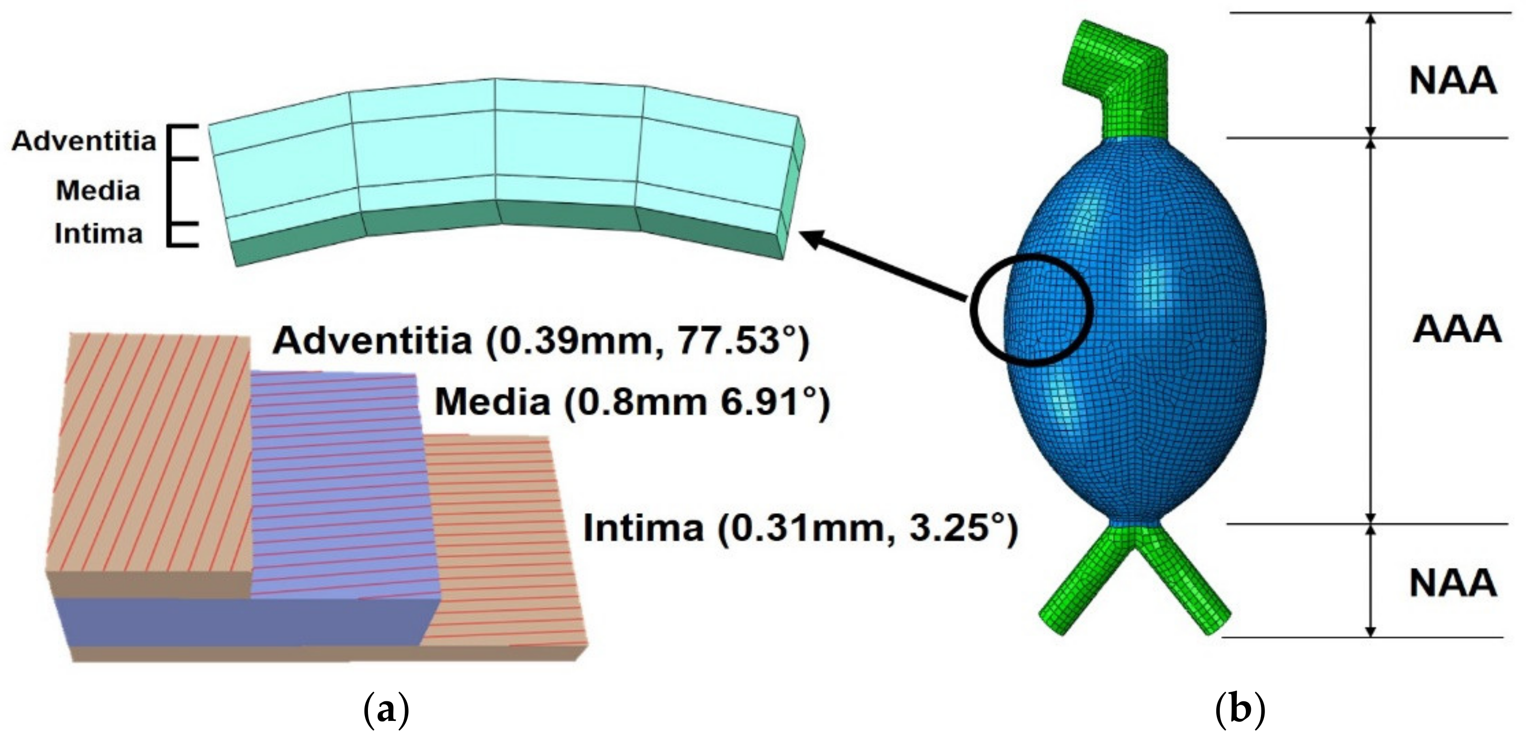
All finite element models created in this study simulated the curved surfaces based on previous measurements. All models were generated from the common iliac artery to the renal artery. The neck length differs among patients; as such, it was assumed to be 30 mm. Moreover, Azar et al. [20] suggested the gradual reduction of the proximal diameter of the iliac artery from 13 to 10.3 mm along the considered length of the vessel. In addition, the aortic wall thickness was set as 1.5 mm using the average aortic wall thickness suggested by Raghavan et al. [25]. The arterial wall was divided into three layers with different thicknesses and fiber directions: intima, media, and adventitia. The fiber direction orientation and thickness in these layers were set as the experimental mean values suggested by Niestrawska et al. [22]. The thickness of each layer of the aorta was set to 0.31, 0.8, and 0.39 mm (intima, media, and adventitia, respectively), which were 0.21%, 0.53%, and 26% of the entire aortic thickness. The fiber direction’s orientation in the intima, media, and adventitia was set as 3.25°, 6.91°, and 77.53°, respectively. In the modeling stage, the neck and iliac arteries were classified as normal tissues based on the diameter of the aorta, and the swollen section was classified as an AAA tissue. The divided model and information on each layer of the arterial wall are shown in Figure 3.

2.6. Loading and Boundary Condition of AAA Model

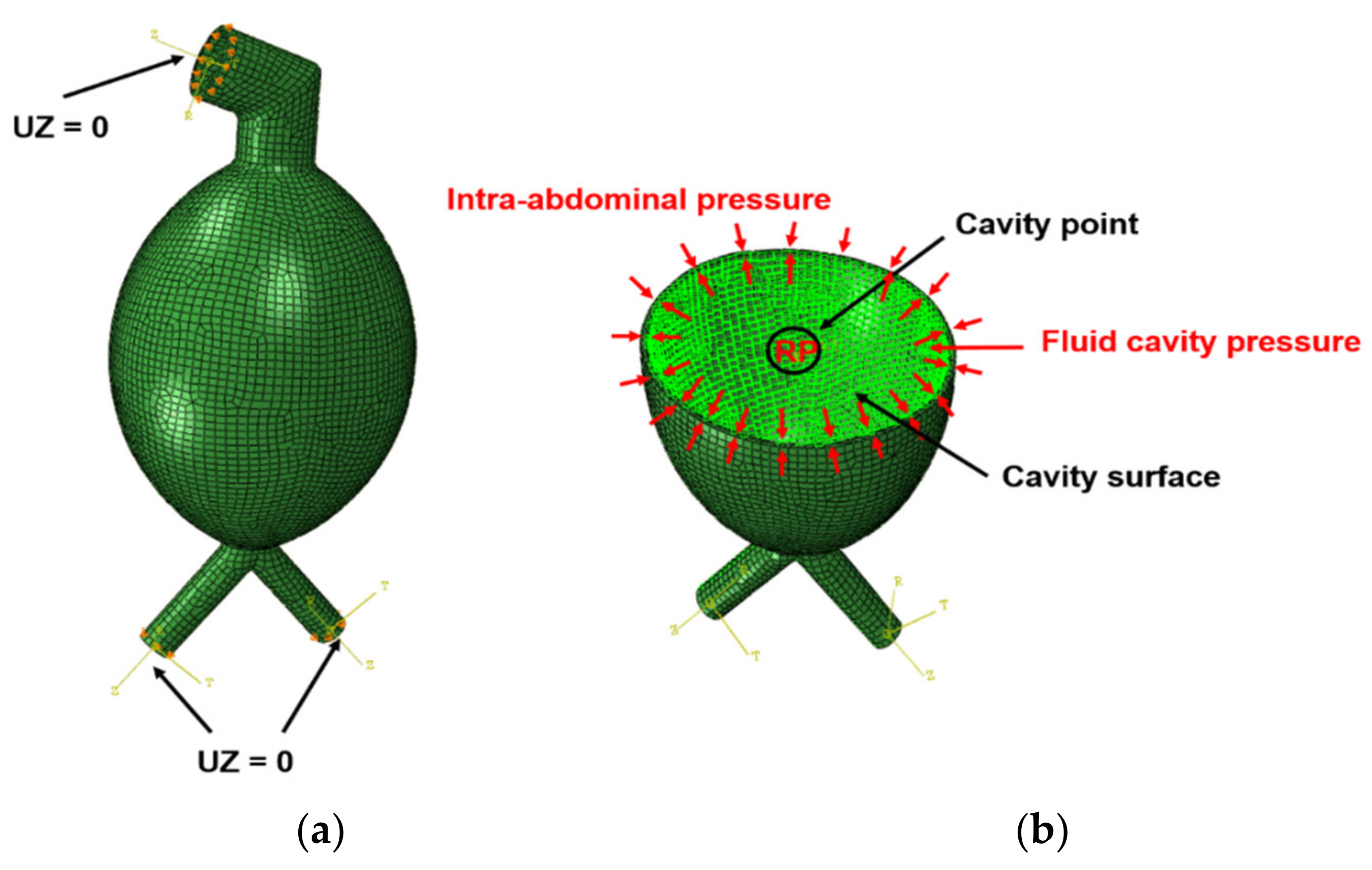
Figure 4 presents the boundary and loading conditions. To prevent the applied model from moving and thus preserve the diameter expansion of the ring part, a reference point was set at the center of the ring (top and bottom of the model). The cylindrical coordinate system was set, and the degree of freedom in the z-axis direction was fixed. In addition, a fluid cavity was used to simulate blood pressure. First, a reference point was designated at the center of the model, and the cavity point was set at that position; the inner wall was set as the cavity surface. A uniform pressure of 120 mm Hg (16 kPa) was applied as the maximum systolic blood pressure in the cardiac cycle. In addition, a uniform pressure of 7 mm Hg (0.93 kPa) was applied to the inner wall to express the abdominal pressure. The density of the inner fluid and bulk modulus of blood were set as 1.06 × 10⁻⁹ t/mm3 and 2.66 GPa, respectively [26,27].

3. Results

3.1. Material Contants of AAA

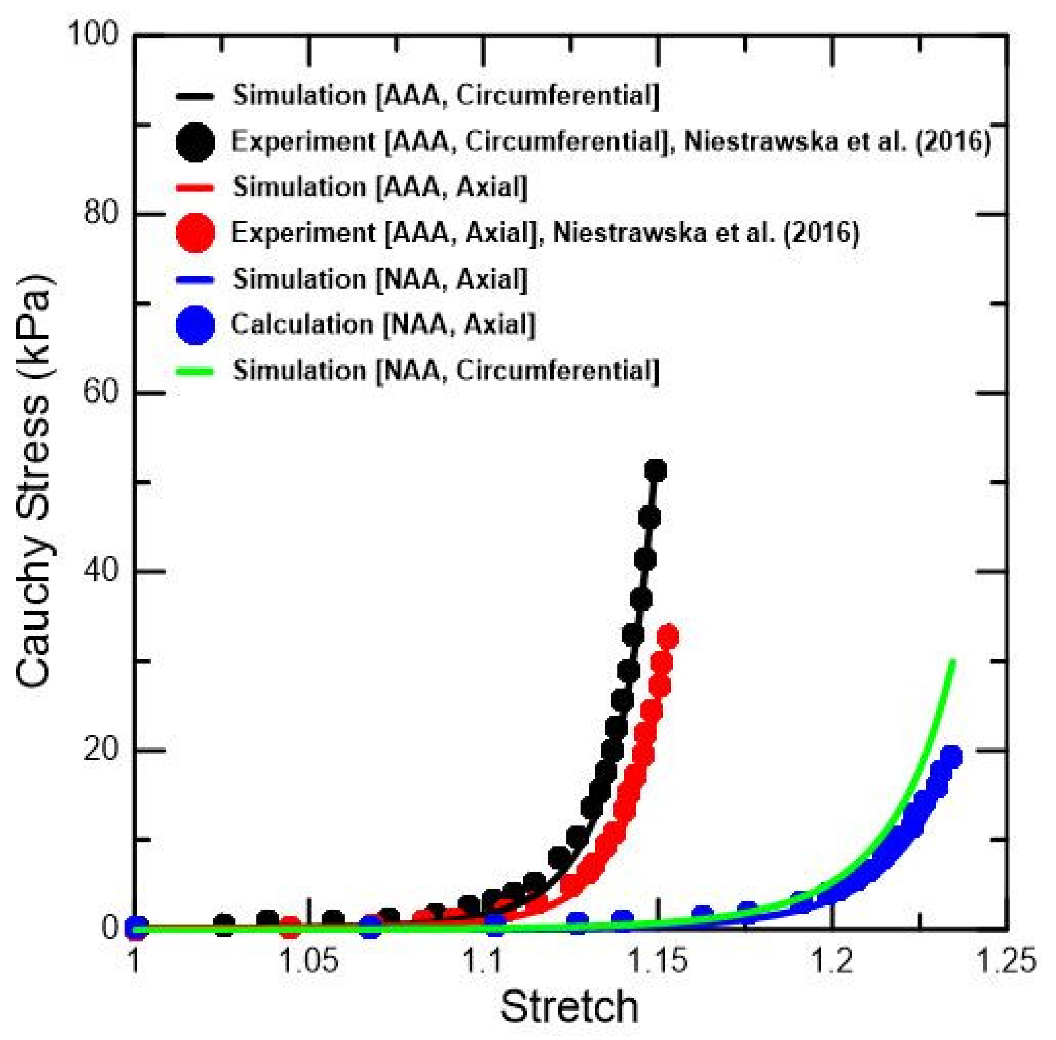
To prove the reliability of the simulation, the experimental and simulation results were compared and validated, as shown in Figure 5. The material constants of the Holzapfel model used in this simulation were calculated based on the comparative study between the experimental and simulation results. Geest et al. [21] performed a biaxial tensile test on NAA and AAA specimens at a strain rate of 12 mm/min, and Niestrawska et al. [22] tested AAA specimens at a strain rate of 3 mm/min. First, the ratio of the tensile stress and tensile stretch of the NAA and AAA tissues was calculated using the results of the biaxial tensile test under a 1:1 tension ratio conducted by Geest et al. [21]. This computed ratio was then substituted for the results of the biaxial tensile test of the AAA tissue performed by Niestrawska et al. [22]. Consequently, the stress–stretch curves in the circumferential and axial directions of the NAA and AAA tissues under the same strain rates were derived and calculated from the simulation results, and were compared with the experimental results, as shown in Figure 5. The material constants used are reported in Table 1.
The arterial tissue has various tensile characteristics depending on the loading conditions, because they are composed of three layers with different fiber directions according to the layer. Moreover, as the aneurysm progresses, the arteries harden; hence, the tensile stress tends to increase, and the stretch decreases. Consequently, the tensile stress value in the sample on the circumferentially oriented strip of AAA was 51.4 kPa, which was 63.8% and 58.4% higher than those in the samples on the axially oriented and circumferentially oriented strips of NAA, respectively. In contrast, the tensile stretch values in the sample on the AAA strip were both 1.15, which was 7.3% lower than in the sample on the NAA strip. Therefore, arterial tissue appears to have different tensile characteristics depending on the aneurysm progression and fiber orientation. In addition, the correlation between the simulation and experimental results demonstrated error rates (1− (experimental results/simulation results)) of 0.002 and 0.02 in the axial and circumferential directions in the AAA tissue, respectively. In the NAA tissue, the axial direction error rate was confirmed to be 0.02.

3.2. Measurements in Patients with AAA and Simulation Scenario Selection

The CT data of 152 patient with AAA were collated, and the aneurysm diameter, height, neck angle, and iliac angle were measured, as summarized in Table 2. The simulation scenario was also selected based on the measured geometric parameters. The scenario was selected to reflect the values between the maximum and minimum measurements, which were divided by appropriate ratios. Each parameter was expressed as DdHhNAnIAi. In this nomenclature, D is the aneurysm diameter (3 cases: 40, 80, and 120 mm); H is the height (2 cases: 110 and 190 mm); NA is the neck angle (3 cases: 20°, 80°, and 140°); and IA is the iliac angle (3 cases: 0°, 70°, and 140°) for a total of 54 cases. An unrealistic phenomenon occurred when the height was small and the aneurysm diameter was large; two cases were selected.

3.3. Scenario Simulation Results

The simulation was performed in a scenario considering the measurement range of the aneurysm diameter, height, neck angle, and iliac angle based on the CT data of patients with AAA. Figure 6 illustrates the stress distributions of the loaded maximum blood pressure in the systole of the cardiac cycle based on the scenario. To avoid the concentration of stress, the PWS was measured in the AAA sac; the total PWS for the scenario is presented in the Appendix A. In particular, in this study, the maximum principal stress values were compared to examine the variation in the PWS according to the maximum systolic blood pressure in the cardiac cycle.
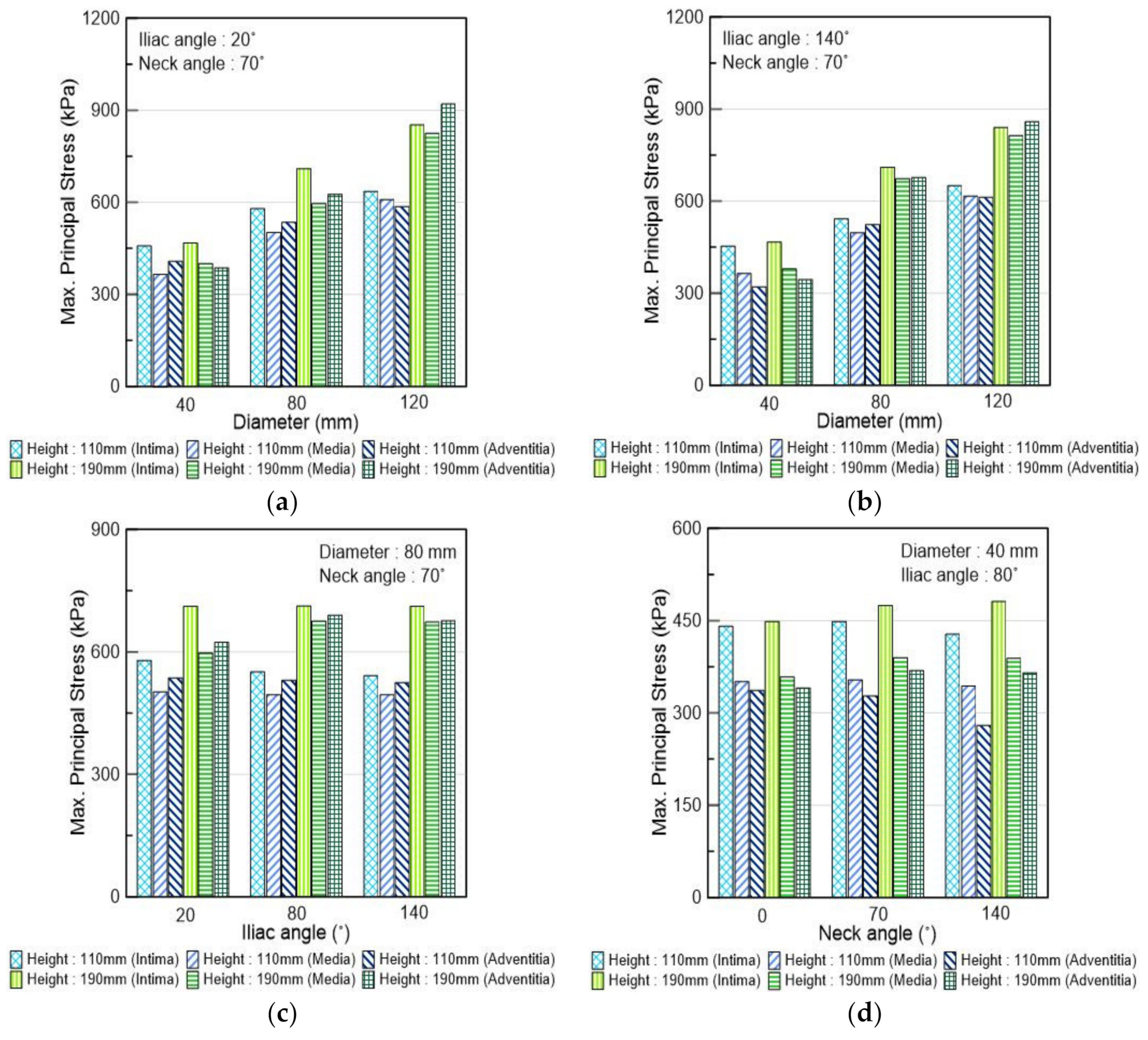
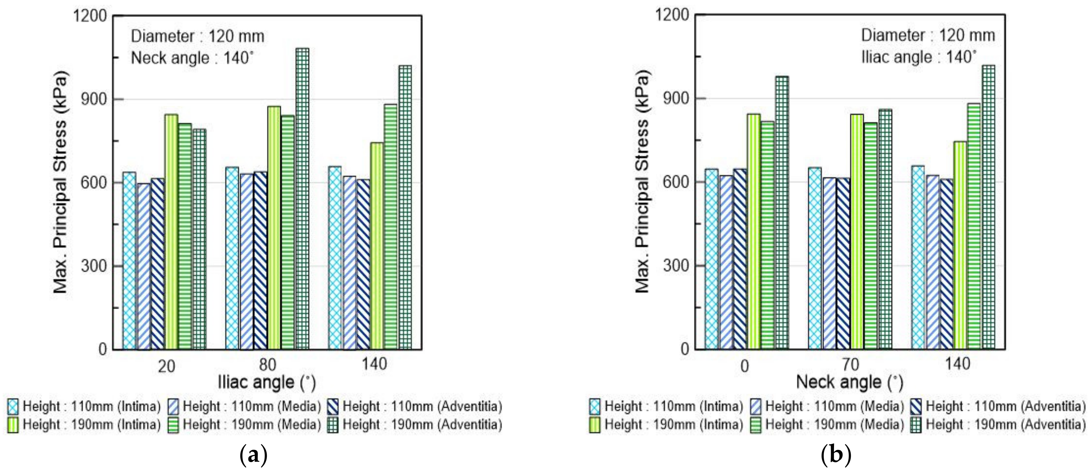
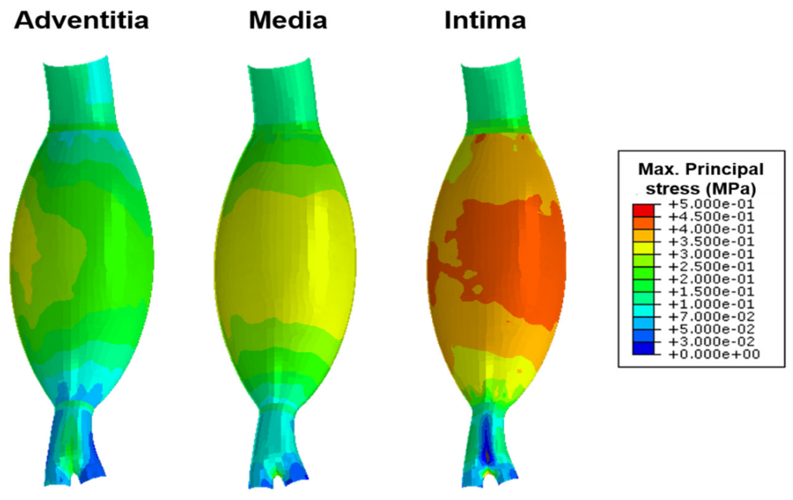
The PWS tended to increase as the aneurysm diameter increased. In particular, when the aneurysm diameter values were 80 and 120 mm, the PWS increased by 30.2% and 36.9% on average as the height increased, respectively. This can be attributed to the changes in the curvature of the AAA model. When the aneurysm diameter was 40 mm and the neck angle increased, the PWS tended to increase slightly; however, this trend was not observed when the aneurysm diameter values were 80 and 120 mm. Similarly, the PWS did not exhibit any trend when the value of the iliac angle was changed, as shown in Figure 7. It was confirmed that at given values of the aneurysm diameter and height, the PWS significantly changed when the iliac angle and neck angle were changed; however, no trend was exhibited, as shown in Figure 8. Further, it was verified that the values of PWS ascended in the order of intima, adventitia, and media, as shown in Figure 9.

4. Discussion

In the biomechanical analysis, the AAA ruptures when the PWS exceeds the aortic strength; evidently, the PWS is a major predictor of AAA rupture. In this study, the correlation between AAA geometry and PWS was analyzed using a computational analysis approach. To accomplish this, the study was conducted in two phases: the calculation of a material constant for simulating the NAA and AAA behaviors, and the scenario simulation based on the AAA geometry.
In the calculation of the material constant phase, first, the biaxial tensile test results of the NAA and AAA tissues were investigated to establish the tensile stress and stretch. In addition, the simulation techniques were verified, and the material constants were calculated by comparing the simulation results with those of the Holzapfel model and the experiments. The sample on the circumferentially oriented strip tended to have a higher tensile stress value than the sample on the axially oriented strip, because the arterial tissue was composed of three layers with different fiber orientations according to the layer. Moreover, the AAA tissue tended to have a higher tensile stress value than the NAA tissue; these results were similar to those of Geest et al. and Xiong et al. [21,28].
In the scenario simulation phase, the AAA geometry (aneurysm diameter, height, neck angle, and iliac angle) was measured using the AAA patient-based three-dimensional model, which was reconstructed in a modeling program, thus creating the scenario simulations. Further, the model was classified into AAA and NAA tissues according to the diameter, and different material constants were set to simulate the behavioral characteristics of the aorta. The correlation between the PWS and AAA geometries was evaluated by the scenario simulation. The increase in aneurysm diameter was found to increase the PWS; this trend was also suggested by other studies [1,17,18,19,20]. When the aneurysm diameter was small, the stress variation was small even when the height was changed; however, when the diameter was large, the stress increased when the height was changed. This was because when the aneurysm diameter was small and the height was large, the curvature became considerably smoother, resulting in a moderate variation in wall stress. In contrast, when both aneurysm diameter and height were large, the wall stress increased even more because the model’s curved surface rapidly changed. However, the neck angle and iliac angle did not show any distinct patterns even when the values were changed. In addition, the magnitude of the PWS was observed in the order of intima, adventitia, and media. The intima had the largest stress because it was the thinnest and received the load directly from the inside. The stress in the outermost adventitia was higher than that in the media because the latter was thicker than the former. Other studies suggested that although the material constants of each layer differed, the intima experienced the greatest stress [29].
There were certain limitations in this study. First, the geometric parameters of the AAA were not sufficiently considered. Previous studies have shown that when asymmetry is introduced into the AAA model, the PWS increases by 48% [3]. In addition, when the axial extent, circumferential extent, and tortuosity in the XZ plane and YZ plane increased, the PWS increased; however, as the thickness increased, the PWS decreased [7]. Forty-seven indicators were selected for the geometry of the AAA and statistically analyzed. It was confirmed that seven indicators had significant effects on the PWS and were appropriate for discriminating AAA [8]. The application of these various factors to this study resulted in different PWS values. Second, some AAA patients had hypertension but were considered to be under normotensive conditions. In our model, when hypertension was simulated, a higher PWS was observed. Third, varying the arterial wall thickness was difficult to implement; hence, a constant thickness was assumed. The study of Shang et al. [9] found that in the case of symptomatic aortic aneurysms, the variable wall thickness model compared with the uniform wall thickness model exhibited a considerably higher expansion rate. Fourth, the spacing among the parameters was overly wide, such that a clear observation of the trend was difficult. Fifth, the same material constants were applied to each layer of the aortic wall. de Lucio et al. [29] employed different material constants for each layer and reported that the intima received most of the stress. In addition, the same fiber orientations of the aorta were applied to all geometry models. It is difficult to consider the fiber orientations in all patients, because the fiber angle cannot be measured from the living tissue. Therefore, in this study, the representative fiber orientation values obtained from the experiment were considered. Finally, although the Holzapfel model has the advantage of a fast calculation time to simulate the material behavior, it includes the same reference configuration of collagen and elastin. Thus, it is more efficient to apply a constitutive model, such as a constrained mixture model, to describe the physical phenomenon of the aortic tissue. However, the Holzapfel model has the advantage of a fast calculation time, so it may be better for use in industries for medical devices. If the foregoing problems are resolved, it is believed that more significant results may be obtained.
In the next study, the authors intend to apply symmetry, tortuosity, and ILT to the AAA model, as well as to implement a loading condition considering hypertension. In addition, the results of the biaxial tensile test for each layer are to be investigated, and the material constants of the Holzapfel model for each layer are to be determined using the technique that is presented in the current study. Finally, by expanding the scenario for various fiber orientations, the creation of a database on the damage criterion and correlation between the PWS, which includes the stress in the layers and geometric parameters intended for clinical practice, is anticipated.

5. Conclusions

In this study, a scenario simulation was performed to estimate the stress according to the AAA geometry. To determine the material constants in the numerical model, a biaxial tensile test of the samples extracted from the AAA was undertaken. In addition, the reliability of the simulation method was determined by comparing the test and simulation results of the stress–strain curve of the specimen. Furthermore, the CT data of AAA patients were analyzed to create and perform simulation scenarios, and the PWS values according to the geometry of the AAA were compared and analyzed. The following conclusions were derived. As the aneurysm diameter increased, the PWS distinctly increased; however, even when the neck and iliac angles were changed, the PWS did not change significantly. In contrast, as the height and aneurysm diameter increased, the PWS increased significantly.
The results obtained in the present study are expected to aid in comprehending the effect of geometric parameters and their changes on the AAA stress in patients with AAA.

Author Contributions

Conceptualization, C.W.L., C.-S.L. and D.R.; data curation, J.-H.Y., C.W.L., U.H., C.-S.L. and D.R.; formal analysis, J.-H.Y. and D.R.; funding acquisition, C.W.L., C.-S.L. and D.R.; investigation, J.-H.Y., C.W.L. and D.R.; methodology, J.-H.Y., C.-S.L. and D.R.; project administration, C.W.L., U.H., C.-S.L. and D.R.; resources, C.W.L. and U.H.; software, J.-H.Y., C.-S.L. and D.R.; supervision, C.W.L. and U.H.; validation, J.-H.Y., C.W.L., C.-S.L. and D.R.; visualization, J.-H.Y.; writing—original draft, J.-H.Y., C.-S.L. and D.R.; writing—review and editing, J.-H.Y., C.W.L., U.H., C.-S.L. and D.R. All authors have read and agreed to the published version of the manuscript.

Funding

This work was supported by the National Research Foundation of Korea (NRF) grant funded by the Korean Government (MSIT) (No. NRF-2018R1A6A3A01012664, DMR; No. NRF-2018R1C1B6007145, CWL; No. NRF-2019R1F1A1062037, CSL).

Institutional Review Board Statement

The study was conducted according to the guidelines of the Declaration of Helsinki, and approved by the Institutional Review Board of Pusan National University Hospital (IRB No. 1706015056).

Informed Consent Statement

Informed consent was obtained from all subjects involved in the study.

Data Availability Statement

Not applicable.

Conflicts of Interest

The authors declare no conflict of interest. The funder had no role in the study design, data collection and analyses, the writing of the manuscript, or in the decision to publish the results.

Appendix A

Table A1 summarizes the results of the scenario simulation conducted in this study. All PWS values were measured in the AAA sac.
Table A1. PWS measurements in the simulated scenario.
DdHhNAnIAiAdventitia (kPa)Media (kPa)Intima (kPa)
D40H110NA0IA20357.856357.064444.306
D40H110NA0IA80336.68350.636440.584
D40H110NA0IA140344.756359.684441.998
D40H190NA0IA20366.868376.335464.93
D40H190NA0IA80341.025358.598449.266
D40H190NA0IA140370.371381.259398.85
D40H110NA70IA20408.545366.859458.022
D40H110NA70IA80327.661353.739448.409
D40H110NA70IA140321.392362.292453.608
D40H190NA70IA20384.403401.012468.754
D40H190NA70IA80369.512389.926475.351
D40H190NA70IA140344.925377.789467.515
D40H110NA140IA20428.71420.968484.413
D40H110NA140IA80279.652343.531427.682
D40H110NA140IA140358.445365.581451.361
D40H190NA140IA20442.726400.205509.011
D40H190NA140IA80365.698388.783481.649
D40H190NA140IA140393.411398.98491.017
D80H110NA0IA20525.382502.761531.946
D80H110NA0IA80595.655505.547549.219
D80H110NA0IA140514.826501.778548.356
D80H190NA0IA20721.917683.943730.629
D80H190NA0IA80685.424672.681721.127
D80H190NA0IA140714.781679.127718.698
D80H110NA70IA20535.609503.137579.57
D80H110NA70IA80529.957495.819551.566
D80H110NA70IA140524.229495.498542.27
D80H190NA70IA20624.29596.221710.945
D80H190NA70IA80690.938674.51712.007
D80H190NA70IA140677.435671.997711.378
D80H110NA140IA20634.462504.617560.634
D80H110NA140IA80550.968496.806577.645
D80H110NA140IA140575.293495.328541.099
D80H190NA140IA20725.316675.627730.46
D80H190NA140IA80712.872671.491716.558
D80H190NA140IA140737.953706.509748.335
D120H110NA0IA20634.736605.533637.874
D120H110NA0IA80635.262624.018659.785
D120H110NA0IA140646.979623.436645.982
D120H190NA0IA20886.176821.801842.241
D120H190NA0IA80765.492790.705815.276
D120H190NA0IA140979.02817.703843.217
D120H110NA70IA20587.573610.675635.772
D120H110NA70IA80599.654633.134644.765
D120H110NA70IA140613.574615.103651.245
D120H190NA70IA20918.297826.263853.297
D120H190NA70IA80929.279854.259871.757
D120H190NA70IA140859.846812.894841.455
D120H110NA140IA20613.079598.188636.752
D120H110NA140IA80638.058633.682654.637
D120H110NA140IA140609.531624.385657.826
D120H190NA140IA20790.219812.858845.014
D120H190NA140IA801081.99841.488875.06
D120H190NA140IA1401019.02882.521743.775

References

  1. Fillinger, M.F.; Marra, S.P.; Raghavan, M.L.; Kennedy, F.E. Prediction of rupture risk in abdominal aortic aneurysm during observation: Wall stress versus diameter. J. Vasc. Surg. 2003, 37, 724–732. [Google Scholar] [CrossRef] [PubMed] [Green Version]
  2. Fillinger, M.F.; Raghavan, M.L.; Marra, S.P.; Cronenwett, J.L.; Kennedy, F.E. In vivo analysis of mechanical wall stress and abdominal aortic aneurysm rupture risk. J. Vasc. Surg. 2002, 36, 589–597. [Google Scholar] [CrossRef] [PubMed]
  3. Doyle, B.J.; Callanan, A.; Burke, P.E.; Grace, P.A.; Walsh, M.T.; Vorp, D.A.; McGloughlin, T.M. Vessel asymmetry as an additional diagnostic tool in the assessment of abdominal aortic aneurysms. J. Vasc. Surg. 2009, 49, 443–454. [Google Scholar] [CrossRef] [PubMed] [Green Version]
  4. Giannoglou, G.; Giannakoulas, G.; Soulis, J.; Chatzizisis, Y.; Perdikides, T.; Melas, N.; Parcharidis, G.; Louridas, G. Predicting the risk of rupture of abdominal aortic aneurysms by utilizing various geometrical parameters: Revisiting the diameter criterion. Angiology 2006, 57, 487–494. [Google Scholar] [CrossRef] [PubMed]
  5. Geest, J.P.V.; di Martino, E.S.; Bohra, A.; Makaroun, M.S.; Vorp, D.A. A biomechanics-based rupture potential index for abdominal aortic aneurysm risk assessment: Demonstrative application. Ann. N. Y. Acad. Sci. 2006, 1085, 11–21. [Google Scholar] [CrossRef]
  6. Doyle, B.J.; Callanan, A.; Walsh, M.T.; Grace, P.A.; McGloughlin, T.M. A finite element analysis rupture index (FEARI) as an additional tool for abdominal aortic aneurysm rupture prediction. Vasc. Dis. Prev. 2009, 6, 114–121. [Google Scholar] [CrossRef] [Green Version]
  7. Conlisk, N.; Geers, A.J.; McBride, O.M.; Newby, D.E.; Hoskins, P.R. Patient-specific modelling of abdominal aortic aneurysms: The influence of wall thickness on predicted clinical outcomes. Med. Eng. Phys. 2016, 38, 526–537. [Google Scholar] [CrossRef] [Green Version]
  8. Raut, S.S.; Jana, A.; de Oliveira, V.; Muluk, S.C.; Finol, E.A. The importance of patient-specific regionally varying wall thickness in abdominal aortic aneurysm biomechanics. J. Biomech. Eng. 2013, 135, 81010. [Google Scholar] [CrossRef] [Green Version]
  9. Shang, E.K.; Nathan, D.P.; Woo, E.Y.; Fairman, R.M.; Wang, G.J.; Gorman, R.C.; Gorman, J.H., III; Jackson, B.M. Local wall thickness in finite element models improves prediction of abdominal aortic aneurysm growth. J. Vasc. Surg. 2015, 61, 217–223. [Google Scholar] [CrossRef] [Green Version]
  10. Mower, W.R.; Quiñones, W.J.; Gambhir, S.S. Effect of intraluminal thrombus on abdominal aortic aneurysm wall stress. J. Vasc. Surg. 1997, 26, 602–608. [Google Scholar] [CrossRef] [Green Version]
  11. Wang, D.H.; Makaroun, M.S.; Webster, M.W.; Vorp, D.A. Effect of intraluminal thrombus on wall stress in patient-specific models of abdominal aortic aneurysm. J. Vasc. Surg. 2002, 36, 598–604. [Google Scholar] [CrossRef] [PubMed]
  12. Georgakarakos, E.; Ioannou, C.; Kamarianakis, Y.; Papaharilaou, Y.; Kostas, T.; Manousaki, E.; Katsamouris, A. The role of geometric parameters in the prediction of abdominal aortic aneurysm wall stress. Eur. J. Vasc. Endovasc. Surg. 2010, 39, 42–48. [Google Scholar] [CrossRef] [PubMed] [Green Version]
  13. Polzer, S.; Gasser, T.C.; Swedenborg, J.; Bursa, J. The impact of intraluminal thrombus failure on the mechanical stress in the wall of abdominal aortic aneurysms. Eur. J. Vasc. Endovasc. Surg. 2011, 41, 467–473. [Google Scholar] [CrossRef] [PubMed] [Green Version]
  14. Haller, S.J.; Crawford, J.D.; Courchaine, K.M.; Bohannan, C.J.; Landry, G.J.; Moneta, G.L.; Azarbal, A.F.; Rugonyi, S. Intraluminal thrombus is associated with early rupture of abdominal aortic aneurysm. J. Vasc. Surg. 2018, 67, e1051–e1058. [Google Scholar] [CrossRef] [PubMed] [Green Version]
  15. Speelman, L.; Bohra, A.; Bosboom, E.M.H.; Schurink, G.W.H.; van de Vosse, F.N.; Makaroun, M.S.; Vorp, D.A. Effects of wall calcifications in patient-specific wall stress analyses of abdominal aortic aneurysms. J. Biomech. Eng. 2007, 129, 105–109. [Google Scholar] [CrossRef] [PubMed]
  16. Li, Z.-Y.; Jean, U.; Tang, T.Y.; Soh, E.; See, T.C.; Gillard, J.H. Impact of calcification and intraluminal thrombus on the computed wall stresses of abdominal aortic aneurysm. J. Vasc. Surg. 2008, 47, 928–935. [Google Scholar] [CrossRef]
  17. Vorp, D.A.; Raghavan, M.; Webster, M.W. Mechanical wall stress in abdominal aortic aneurysm: Influence of diameter and asymmetry. J. Vasc. Surg. 1998, 27, 632–639. [Google Scholar] [CrossRef] [Green Version]
  18. Shum, J.; Martufi, G.; di Martino, E.; Washington, C.B.; Grisafi, J.; Muluk, S.C.; Finol, E.A. Quantitative assessment of abdominal aortic aneurysm geometry. Ann. Biomed. Eng. 2011, 39, 277–286. [Google Scholar] [CrossRef] [Green Version]
  19. Urrutia, J.; Roy, A.; Raut, S.S.; Antón, R.; Muluk, S.C.; Finol, E.A. Geometric surrogates of abdominal aortic aneurysm wall mechanics. Med. Eng. Phys. 2018, 59, 43–49. [Google Scholar] [CrossRef]
  20. Azar, D.; Ohadi, D.; Rachev, A.; Eberth, J.F.; Uline, M.J.; Shazly, T. Mechanical and geometrical determinants of wall stress in abdominal aortic aneurysms: A computational study. PLoS ONE 2018, 13, e0192032. [Google Scholar] [CrossRef] [Green Version]
  21. Geest, J.P.V.; Sacks, M.S.; Vorp, D.A. The effects of aneurysm on the biaxial mechanical behavior of human abdominal aorta. J. Biomech. 2006, 39, 1324–1334. [Google Scholar] [CrossRef]
  22. Niestrawska, J.A.; Viertler, C.; Regitnig, P.; Cohnert, T.U.; Sommer, G.; Holzapfel, G.A. Microstructure and mechanics of healthy and aneurysmatic abdominal aortas: Experimental analysis and modelling. J. R. Soc. Interface 2016, 13, 20160620. [Google Scholar] [CrossRef] [PubMed] [Green Version]
  23. Holzapfel, G.A.; Gasser, T.C.; Ogden, R.W. A new constitutive framework for arterial wall mechanics and a comparative study of material models. J. Elast. Phys. Sci. Solids 2000, 61, 1–48. [Google Scholar]
  24. Gasser, T.C.; Ogden, R.W.; Holzapfel, G.A. Hyperelastic modelling of arterial layers with distributed collagen fibre orientations. J. R. Soc. Interface 2006, 3, 15–35. [Google Scholar] [CrossRef]
  25. Raghavan, M.L.; Hanaoka, M.M.; Kratzberg, J.A.; de Lourdes Higuchi, M.; Da Silva, E.S. Biomechanical failure properties and microstructural content of ruptured and unruptured abdominal aortic aneurysms. J. Biomech. 2011, 44, 2501–2507. [Google Scholar] [CrossRef] [PubMed]
  26. Brutin, D.; Sobac, B.; Loquet, B.; Sampol, J. Pattern formation in drying drops of blood. J. Fluid Mech. 2011, 667, 85–95. [Google Scholar] [CrossRef] [Green Version]
  27. Habibi, R.; Devendran, C.; Neild, A. Trapping and patterning of large particles and cells in a 1D ultrasonic standing wave. Lab Chip 2017, 17, 3279–3290. [Google Scholar] [CrossRef]
  28. Xiong, J.; Wang, S.M.; Zhou, W.; Wu, J.G. Measurement and analysis of ultimate mechanical properties, stress-strain curve fit, and elastic modulus formula of human abdominal aortic aneurysm and nonaneurysmal abdominal aorta. J. Vasc. Surg. 2008, 48, 189–195. [Google Scholar] [CrossRef] [Green Version]
  29. De Lucio, M.; García, M.F.; García, J.D.; Rodríguez, L.E.R.; Marcos, F.Á. On the importance of tunica intima in the aging aorta: A three-layered in silico model for computing wall stresses in abdominal aortic aneurysms. Comput. Methods Biomech. Biomed. Eng. 2020, 1–18. [Google Scholar] [CrossRef]
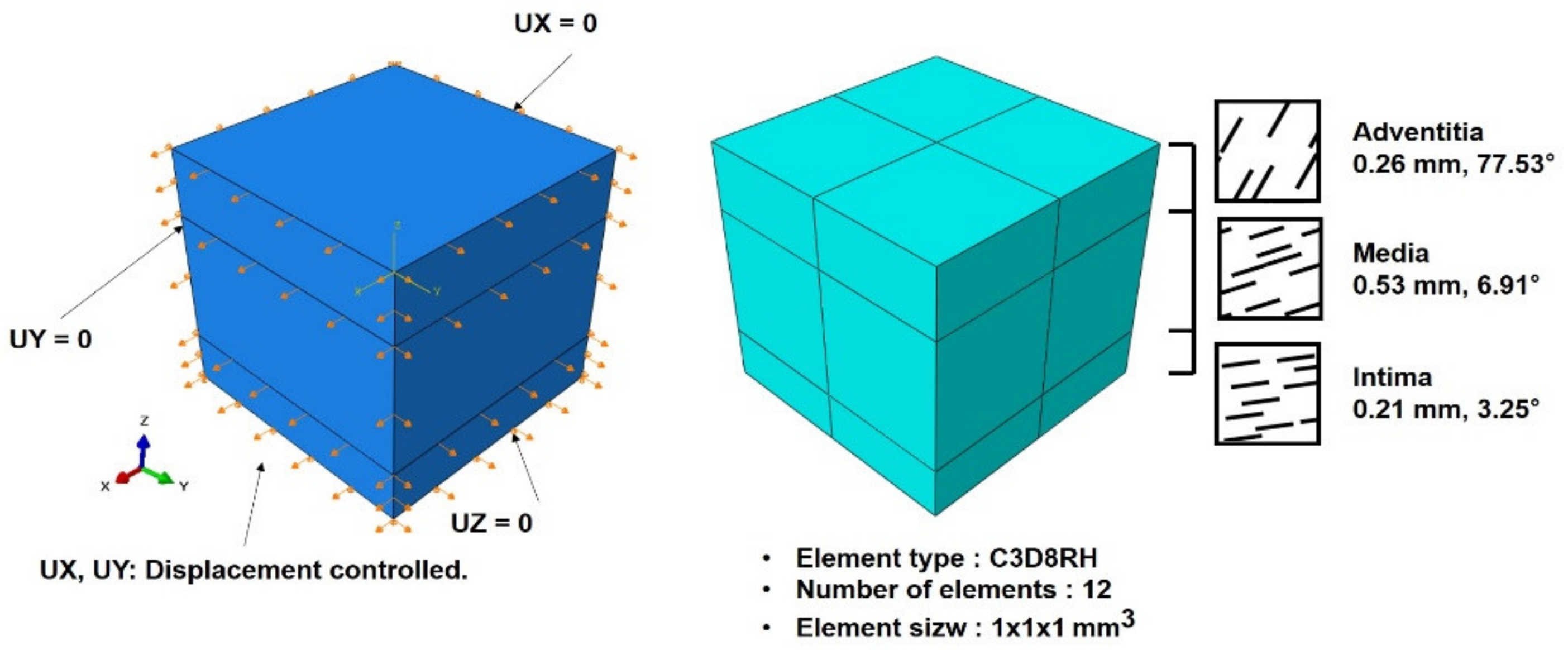
Figure 1. Representative volume element (RVE) model and loading boundary condition for simulation. Fiber orientation was set counterclockwise from the axial direction.
Applsci 11 03195 g001
Figure 2. Geometry of abdominal aortic aneurysm model.
Applsci 11 03195 g002
Figure 3. (a) Fiber orientation and (b) normal aorta and aneurysm region.
Applsci 11 03195 g003
Figure 4. (a) Boundary condition and (b) loading condition in the used fluid cavity.
Applsci 11 03195 g004
Figure 5. Stress–stretch curve of human abdominal aorta tissue from biaxial tensile test and simulations.
Applsci 11 03195 g005
Figure 6. Maximum principal stress contour in inner wall. (a) Diameter: 40 mm; height: 110 mm; (b) diameter: 40 mm; height: 190 mm; (c) diameter: 80 mm; height: 110 mm; (d) diameter: 80 mm; height: 190 mm; (e) diameter: 120 mm; height: 110 mm; and (f) diameter: 120 mm; height: 190 mm.
Applsci 11 03195 g006
Figure 7. Maximum principal stress according to (a,b) diameter; (c) iliac angle; and (d) neck angle.
Applsci 11 03195 g007
Figure 8. Maximum principal stress according to (a) iliac angle and (b) neck angle.
Applsci 11 03195 g008
Figure 9. Maximum principal stress distributions in the adventitia, media, and intima layers of the representative model.
Applsci 11 03195 g009
Table 1. Material constants.
C10 (MPa)K1 (MPa)K2κ
AAA0.031502500.261
NAA0.120610.226
Table 2. Abdominal aortic aneurysm AAA geometrical measurements.
Diameter (mm)Neck Angle (°)Height (mm)Iliac Angle (°)
Minimum41.17.83611.7
Maximum118.1136.9188143.5
Average63.4 ± 14.249.3 ± 22.593.4 ± 28.668.34 ± 22.1
Publisher’s Note: MDPI stays neutral with regard to jurisdictional claims in published maps and institutional affiliations.