1. Introduction
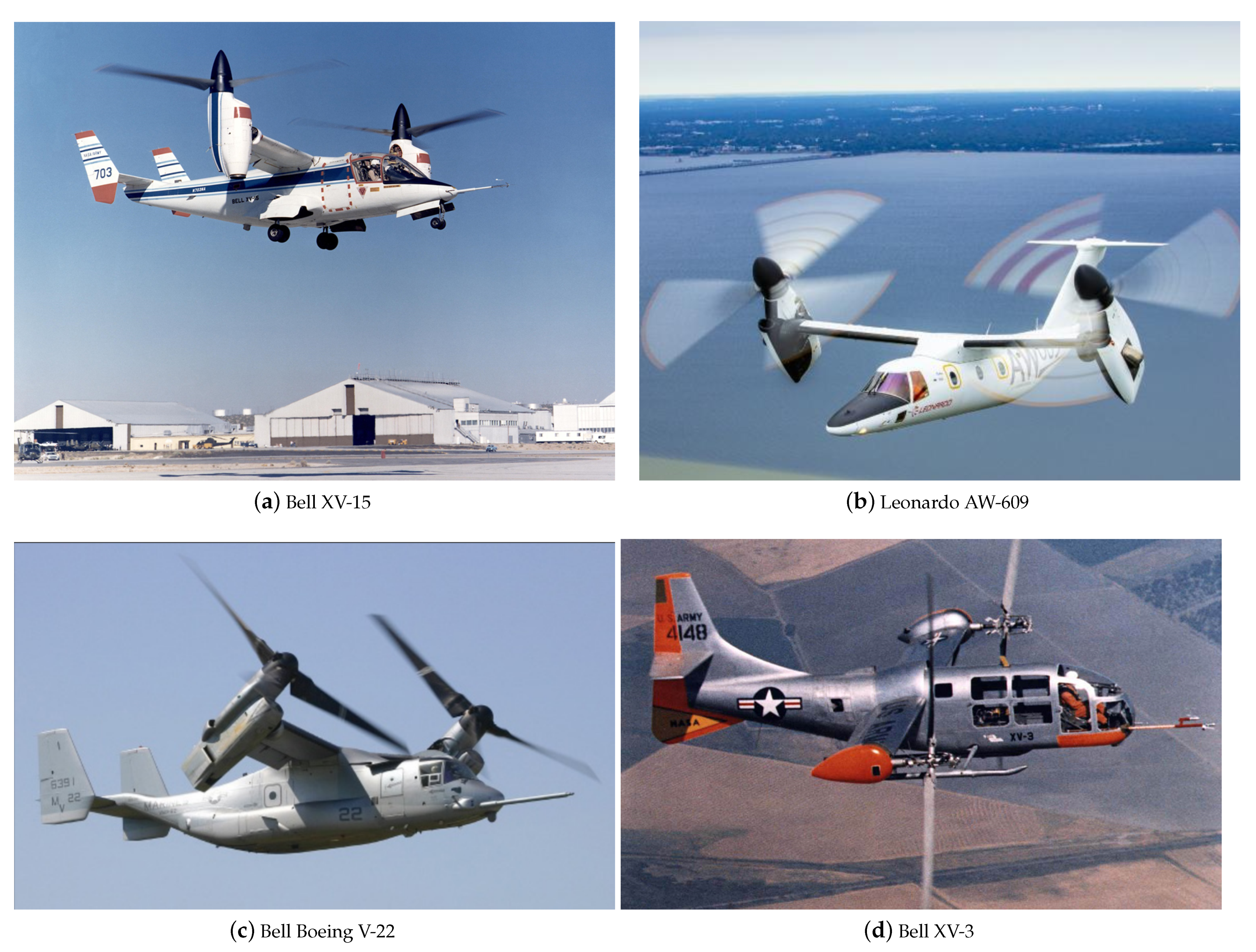
Tiltrotors combine the speed and range of a conventional fixed-wing aircraft with the vertical take-off and landing capabilities of helicopters. Their architecture is typically characterised by two powered rotors that are mounted on tilting nacelles located at the outer portion of the wing. The flight mission of tiltrotors involves different vehicle configurations characterised by several relative angles between rotor nacelles and wing. Indeed, tiltrotors take off as a helicopter with the rotors tilted vertically (see
Figure 1a) and they turn the rotors forward in cruise conditions to behave as a fixed wing airplane (see
Figure 1d). In the conversion phase between take-off and cruise flight conditions, the aircraft rotates the rotors providing different tilting angles between the rotors and wing axis (see
Figure 1b,c). Consequently, tiltrotor aerodynamics are characterised by complex interactions between the rotor wake and wing that are peculiar of the different attitudes experienced by the vehicles during their flight mission. Several experiments have been conducted to investigate rotor–wing interactions, from the early stages of the JVX program [
1,
2] to the present day [
3,
4].
Recent advances in the field of high-performance computing favoured the use of high-fidelity Computational Fluid Dynamics (CFD) for a thorough investigation of the complex aerodynamic interactions that characterise tiltrotor architectures. Indeed, several numerical works employing the use of high-fidelity Navier–Stokes equations solvers for the study of tiltrotor aerodynamics can be found in the literature. Examples of computational studies of tiltrotor aerodynamics are the works by Meakin [
5], Potsdam and Strawn [
6], and Wissink et al. [
7], where hover configurations were simulated while using different implementations of the Navier–Stokes equations.
Moreover, several high-fidelity CFD codes, such as elsA [
9] by ONERA, FLOWer [
10] by DLR and Airbus Helicopters Deutschland, HBM3 by the University of Glasgow [
11], and ROSITA [
12] by Politecnico di Milano, were developed in Europe for rotorcraft application studies. These codes, based on the block-structured grid, finite volume, and Chimera approaches for the simulation of rotating bodies, were used and compared for the study of the aerodynamics of the tiltwing aircraft ERICA [
13,
14] and, in particular, within the European project NICETRIP [
15]. In the recent literature, several numerical works were carried out to simulate the aerodynamics of the XV-15 tiltrotor aircraft using high-fidelity CFD tools. Indeed, in these works, Lim and Tran et al. [
16,
17,
18,
19] investigated the main aerodynamic interactions between the rotor and the wing of the XV-15 tiltrotor.
Nevertheless, time-accurate URANS simulations of tiltrotor aircraft configurations still require a huge computational effort. Thus, high-fidelity CFD tools are usually employed for the detailed study of a limited number of tiltrotor configurations in steady-state conditions, as done in [
16,
17]. Mid-fidelity aerodynamic solvers that are based on unsteady panel methods are considered of great interest in the field of rotorcraft simulations. As a matter of fact, the limited computational effort that is required by these numerical tools enables one to perform the large number of aerodynamic simulations required for the preliminary design of novel rotary-wing vehicles. To cite few examples of numerical works involving the use of unsteady panel methods for rotorcraft applications, the University of Roma Tre developed a direct panel method based on a novel boundary integral formulation for the velocity potential that was used both for the investigation of blade vortex interaction of helicopter rotors [
20] and for the study of wing-proprotor aerodynamic interaction of tiltrotors [
21]. More recently, DLR developed an unsteady panel, free-wake code that was used for the aerodynamic study of a complex rotorcraft configurations, such as the Airbus RACER compound helicopter [
22]. In particular, recent works used the vortex particle method (VPM) [
23,
24] for wake modelling, showing a quite accurate representation of the aerodynamic interactions among several bodies that are typical of complex rotorcraft configurations. To cite few examples, Lu et al. [
25] developed a method for the optimisation of the aerodynamic layout of a helicopter using an aerodynamic model based on viscous VPM combined with an unsteady panel hybrid method to simulate the interactions between the various components of a helicopter. The National Technical University of Athens developed the GENeral Unsteady Vortex Particle (GENUVP) software based on a panel method coupled with a VPM solver that was used for both aerodynamic and aeroacoustic simulations of rotorcraft [
26]. Alvarez and Ning investigated multi-rotors configurations using a VPM-based code [
27], showing good agreement with experimental data. Moreover, Tan et al. used a vortex-based approach coupled with a viscous boundary model to investigate the complex rotorcraft-to-rotorcraft interference problems that occur during shipboard operations—i.e., the flow field and unsteady airloads of a tiltrotor affected by the wake of an upwind tandem rotor [
28].
In recent years, a new flexible mid-fidelity computational tool, called DUST (
www.dust-project.org), was developed as the result of a collaboration between Politecnico di Milano and
by Airbus LLC, aiming to obtain a fast and reliable numerical tool for the aerodynamic simulation of complex rotorcraft configurations, such as eVTOLs aircraft. DUST is an open source code that was developed under an MIT license, simultaneously involving different aerodynamic modelling techniques, such as thick surface panels, thin vortex lattices, and lifting lines for solid bodies, while vortex particles were used for wake modelling. In particular, the implemented vortex particle model for wakes provides a stable Lagrangian description of the free vorticity field in the flow, which is suitable for numerical simulations with strong aerodynamic interactions. Indeed, for instance, DUST was used to simulate the aerodynamics of the full Vahana vehicle that was developed by A
3 by Airbus LLC [
29] characterised by two rows of four rotors in a tandem configuration, showing a quite good agreement with both the flight test data and high-fidelity CFD results [
30]. Moreover, thanks to the low computational effort that is required by the code implementation, DUST was recently employed to perform a parametric study of the rotor-rotor aerodynamic interaction that characterises the cruise flight conditions of an eVTOL aircraft [
31]. Consequently, DUST can be considered in a mature state to be used for the investigation of challenging rotorcraft configurations that are characterised by complex aerodynamic interactions between rotors and wings.
The present work aims to assess the accuracy of the mid-fidelity approach that was implemented in DUST for the simulation of tiltrotor aerodynamics with respect to CFD. In particular, numerical simulations were performed with DUST to show the ability of a mid-fidelity solver to capture the effects of the complex aerodynamic interactions between the rotor wake and the wing typical of the different stages of a tiltrotor flight mission. Indeed, the scope of the work is to investigate the suitability of a mid-fidelity solver for the preliminary design of complex rotorcraft architectures, such as tiltrotors, which require a huge number of numerical simulations. In particular, the work was performed in the framework of the FORMOSA project, which aimed at the design of the novel wing movable surface system of the NextGen Civil Tiltrotor aircraft developed within the framework of the Clean Sky 2–H2020 Programme.
In the present paper, the results of the DUST simulations over a complete tiltrotor model in different flight conditions are compared with the results that were obtained using a numerical approach with a higher fidelity, such as URANS simulations. In particular, the test case considered in the present work is the XV-15 aircraft due to the accessible and comprehensive data available in the literature. Indeed, this vehicle was commonly considered as a reference to validate fluid dynamics code for tiltrotor applications, as achieved, for example, by Garcia et al. [
32]. The numerical activity performed with DUST considered the steady-state conditions of the complete XV-15 tiltrotor aircraft in hover, conversion, and cruise conditions to be compared with the recent results that were obtained with the URANS CFD solver presented in the works by Tran et al. [
16,
17]. Hereafter, the results obtained from these reference works will be outlined as CFD results. The extensive assessment described in the present work clearly indicates the limits and robustness of a mid-fidelity numerical approach with respect to higher-fidelity CFD solvers for the investigation of the main interacting flow features that characterise tiltrotor aerodynamics. Moreover, the results that are presented in this work indicate that mid-fidelity solvers can be considered to be valuable tools for engineers for use in the preliminary phase of the design process of unconventional VTOL aircraft. Consequently, the results presented in this work represent a thorough assessment of a novel milestone in the computational fluid dynamics tools used by the aerospace community for the development and study of the aerodynamics of novel aircraft architectures. The paper is organised, as follows.
Section 2 outlines the numerical approach implemented in DUST.
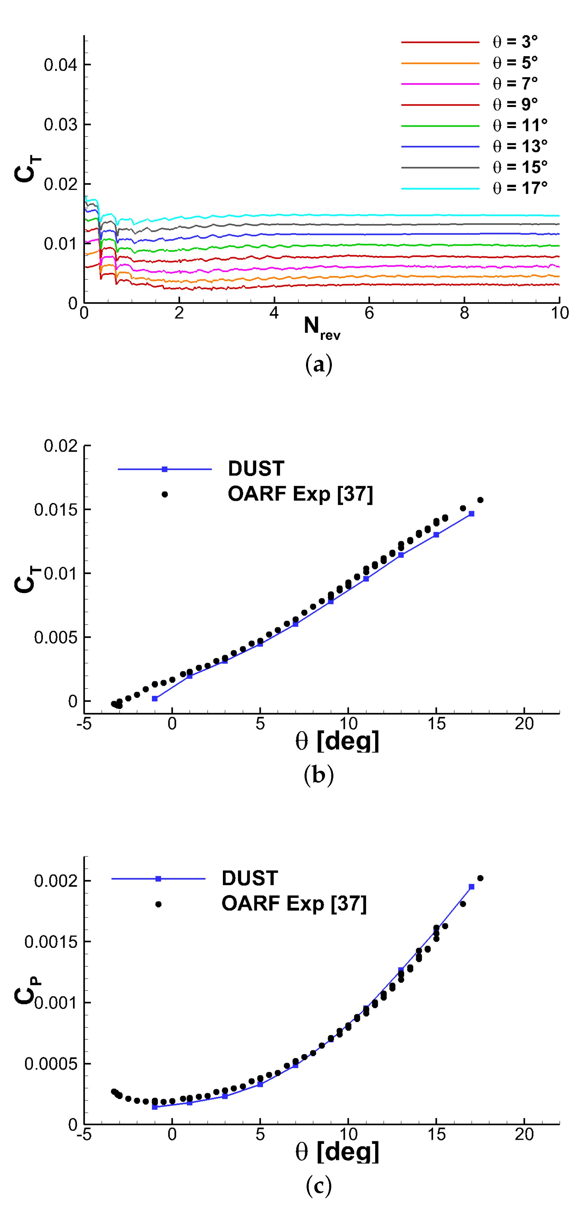
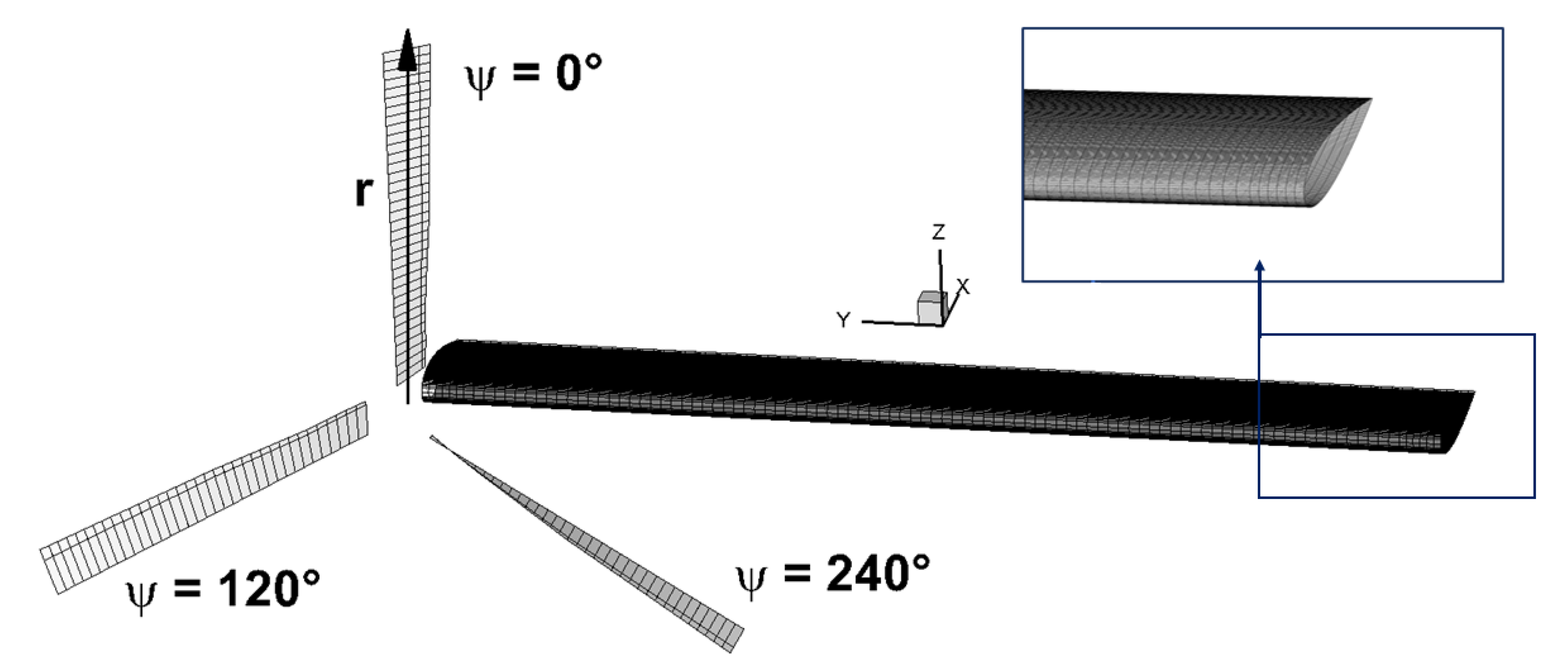
Section 3 provides the description of the numerical models implemented for the study of the XV-15 tiltrotor aerodynamics, along with the validation of the parameters used for DUST simulations by means of comparison with the experimental data available for the single rotor in hover.
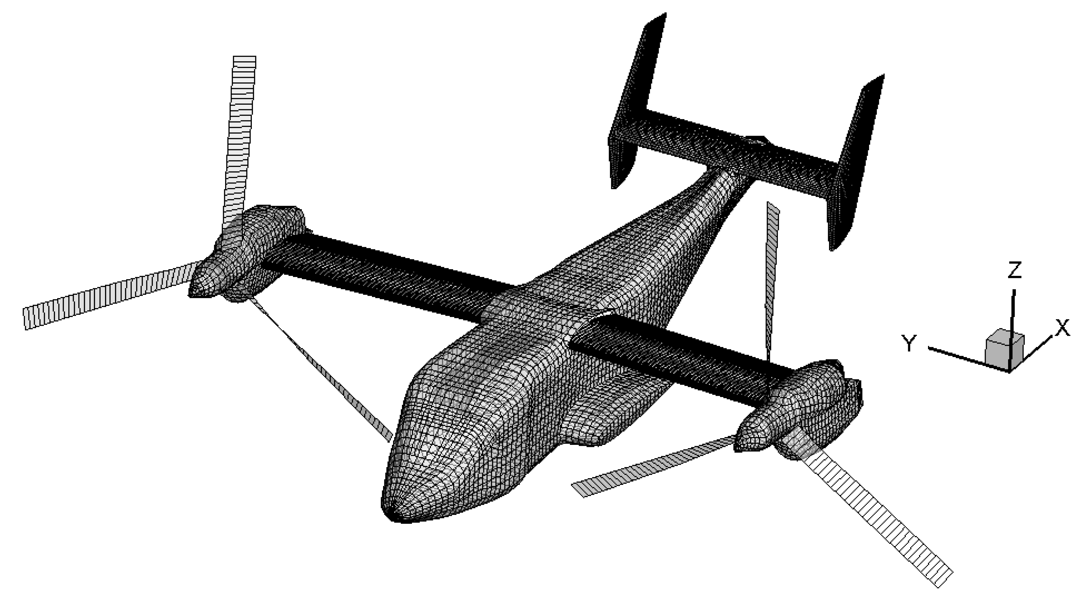
Section 4 presents the main results that were obtained in DUST compared with the CFD simulation results available in the literature, starting from a simplified configuration made up of a single wing and rotor to the complete tiltrotor aircraft in different flight conditions. Conclusions are drawn in
Section 5.
2. Numerical Approach Implemented in DUST
DUST is an open source software that was built with the object-oriented paradigms of the latest FORTRAN standards aiming to solve complex aerodynamics problems with a flexible and reliable approach. The mathematical formulation of the problem relies on Helmholtz’s decomposition of the velocity field
, with
and
being the irrotational and solenoidal contributions, respectively, to recast the aerodynamic problem as a combination of a boundary value problem for the potential part of the velocity and a mixed panels-vortex particles model of the free vorticity in the flow. The solution is advanced in time using a time-stepping algorithm that alternates the solution of a three-dimensional boundary element method for
and the Lagrangian evolution in time of the rotational part of the velocity
. Only the surface mesh of the model is required and different aerodynamic elements allow for different levels of fidelity in the model, ranging from lifting line elements to zero-thickness lifting surfaces and surface panels. A piecewise-uniform distribution of doublets and sources is associated with surface panels, according to a Morino-like formulation for the velocity potential [
33]. Thin lifting bodies can also be modelled as zero-thickness surfaces of vortex lattice elements, for which a velocity-based non-penetration condition is assigned. The mixed potential-velocity formulation of the boundary element problem results in a linear system whose unknown is the intensity of the doublet distribution on the surface panels and the equivalent doublet intensity of the vortex lattice elements.
One-dimensional lifting line elements are used for a proper modelling of lifting bodies with a high aspect ratio, such as rotor blades. These elements naturally represent viscous effects, since they rely on the tabulated aerodynamic lift, drag, and moment coefficients of two-dimensional sections as functions of the relative velocity direction and magnitude. Each lifting line element is modelled as a vortex ring that is composed by the lifting line segment along with its trailing vortices. The last line vortex is released in the wake aligned with the spanwise direction. The intensity
of this vortex ring and, thus, of the lifting line, is determined through a fixed point algorithm solving a nonlinear problem, connecting the intensity of the lifting line elements with the tabulated aerodynamic coefficients of the lifting sections. Both a loosely coupled
method [
34] and a
method [
35] solver are available in the DUST formulation. An iterative procedure is used to solve the nonlinear problem of computing the loads on lifting lines, while taking into account their mutual interference, using the unsteady formulation of the Kutta–Joukowski theorem to retrieve the circulations of the elements from their lift.
A more detailed description of the whole numerical approach implemented in DUST can be found in [
30,
36]. In the following, a brief description of the core of the code that is represented by the implemented VPM is provided.
Vortex Particle Method
The wake shed from the trailing edges of lifting bodies is modeled as a panel wake, which shares the same spatial discretisation that is used to model the lifting bodies and the same formulation as vortex lattice elements in terms of geometry and singularity distribution. When advected downstream, the panel wake is converted into vortex particles in order to obtain a more robust wake formulation that is suitable for the representation of the interactional aerodynamics of both rotorcraft and complex aircraft configurations. The vortex particles method (VPM) [
23,
24] is a Lagrangian grid-free method describing the wake evolution through the rotational component of the velocity field
by means of the material vortex particles used to obtain the approximated vorticity field—namely:
where
is the position,
is the intensity, and
is the radius of the
p-th vortex particle, while
is the cut-off function while considering the vorticity distribution that is induced by each particle. By substituting (
1) in the equation of the dynamics of vorticity,
the dynamical equations for the intensity
and position
of all the material vortex particles to be integrated in time can be obtained, as follows:
The viscosity diffusion term “
” is calculated while using the particle strength exchange (PSE) method, which approximates the Laplacian operator acting on the vorticity field with an integral operator, as reported in [
24].
The mathematical formulation used in the solver relies on the Helmholtz decomposition of the velocity field
. The irrotational velocity
is induced by the free stream velocity, by the singularity distributions of sources and doublets on the body surface, and by the wake panels, while the rotational velocity
is induced by the vortex particles. Moreover, the solenoidal constraint on the rotational velocity,
, is used in order to define the vector potential
, s.t.
. Consequently, Poisson’s equation is obtained for
:
where we consider the gauge condition
, the vorticity field definition
, and the vector identity
. Poisson’s equation solution (
4) reads:
where
is Green’s function of the Laplace equation and
represents its gradient with respect to the first argument.
Substituting the definition of the discretised vorticity field of the particles (
1) into Equation (
6), the contribution of velocity that is induced by the particles can be obtained, as follows:
The discrete kernel
must be consistent with the selected cutoff function
. The cutoff function in the singular vortex particle method is a Dirac delta function, and the Biot–Savart kernel is retrieved. In the DUST implementation, the selected cutoff function
leads to the Rosenhead–Moore kernel:
This is a regular kernel fitting naturally in the Cartesian fast multipole method (FMM) [
37,
38]. The induced rotational velocity
has to be accounted for in the material objects’ convection and in the right-hand side of the linear system of equations for the potential velocity. Moreover, the velocity field gradient is calculated to evaluate the vortex stretching-tilting term with the FMM. Indeed, this term is a function of both the vortex intensities and the particle distance in particle-to-particle interactions [
24].


