Article

Higher-Order-Mode Triple Band Circularly Polarized Rectangular Dielectric Resonator Antenna

by
Muhammad Fitra Zambak
1,
Mohd Najib Mohd Yasin
2,*,
Ismahayati Adam
2,*,
Javed Iqbal
3 and
Mohamed Nasrun Osman
2
1
Magister Teknik Elektro, Universitas Muhammadiyah Sumatera Utara, Kota Medan 20238, Indonesia
2
Advanced Communication Engineering (ACE) Centre of Excellence, Faculty Electronic Engineering Technology, Universiti Malaysia Perlis, Arau 02600, Perlis, Malaysia
3
Electrical Engineering Department, FET Gomal University, University Road, Dera Ismail Khan 29050, Pakistan
*
Authors to whom correspondence should be addressed.
Appl. Sci. 2021, 11(8), 3493; https://doi.org/10.3390/app11083493
Submission received: 14 March 2021 / Revised: 3 April 2021 / Accepted: 7 April 2021 / Published: 13 April 2021

Abstract

:
The paper presents a triband circular polarized rectangular dielectric resonator antenna. A single coaxial cable feeds the DRA to a double stub strip on the DRA side. A patch strip coupled to the feed assists in widening the bandwidth of the proposed DRA. The degenerate mode pair TE 11 x and higher- T E 23 x has been excited to achieve CP and enhance the antenna gain. The higher-order mode has been excited using a low-cost simple excitation mechanism without compromising on the size and shape of the DRA. An impedance bandwidth of 48% with a gain ~6–9 dBic was achieved in all resonance frequencies. Additionally, the AR bandwidth of 5.5%, 4.2%, and 2.76% was obtained at three different frequencies. Note that the proposed DRA exhibits a wide beamwidth of 112o, which is good for better signal reception. A comparison between the measured with simulated results shows that the measured results are matched by the simulated result trends.

1. Introduction

Over the past few decades, the dielectric resonator antenna (DRA) has been the center of attention among antenna researchers. This is due to the prominent features of DRA over the microstrip patch such as high radiation efficiency, high gain, less metallic loss, wide bandwidth, lightweight, and tunable far-field pattern due to several modes in DRA [1,2,3]. The DRAs can be designed in various shapes; however, basic shapes such as rectangular and cylindrical shapes are preferred because of their low cost and ease of fabrication. According to the forms, the rectangular DRA is more favored than cylindrical and hemispherical DRAs owing to flexibility in the option of the acceptable aspect ratio [2,4] considering that it will affect the bandwidth of the DRA antenna. Additionally, the mode degeneracy existing in spherical DRA and cylindrical DRA can be avoided by using a proper rectangular DRA dimension. The mode degeneracy is disfavourable as it increases the cross-pol levels of an antenna and hence limits the antenna performance [5]. On the other hand, considerable attention had focused on the DRAs with circular polarization (CP) as they offered a better quality of signals, alleviate fading and multipath, insensitive to polarization mismatch, which makes them more suitable for wireless communication systems than the linearly polarized (LP) antenna [3,6,7,8,9,10].
Many approaches to achieving CP in DRA have been explored previously, such as the dual and single excitation techniques, but end up with a complex feeding network and larger antenna size [11,12,13]. Alternatively, authors in [14,15] proposed a mechanical method that uses filling fluids inside the DRA. A DRA with simple feeding mechanisms is preferable; however the challenges are in obtaining a wideband AR bandwidth. Different techniques have been introduced previously, such as layering the DR structure [7], modifications on basic DR shapes by drilling and cutting the DRs [3,6,11], multi-dielectric layering [16], and a diode for the reconfigurable band [17].
A strip-fed excitation method to the rectangular DRA is proposed in [2], where adding a parasitic patch at the corner of the DRA structure resulted from a CP DRA. The antenna resonates at 3.4 GHz with 14% bandwidth and 3-dB AR bandwidth of 2.7%. Triband CP DR antenna was proposed in [3,10], where a triple-band dual-sense circularly polarized hybrid DRA is submitted by a modified hexagonal DR is top-loaded by a square microstrip ring (SMR) in [3]. The antenna is fed by a vertical-tapered-strip and resonates at 1.9 GHz, 2.73 GHz, and 3.7 GHz, which exhibit left-handed circular polarization (LHCP) in the lower band. In contrast, right-handed circular polarization (RHCP) is obtained in the upper CP band. While authors in [10] proposed a top-loaded modified Alford loop CP DRA, where the CP occurs at 1.937, 2.45, and 3.51 GHz.
On the other hand, a dual-band CP antenna is demonstrated in [6,7,12,18,19]. A singly fed dual-band CP rectangular DRA, where quasi-TE111 and -TE113 modes are excited to provide dual-frequency at 1.58 GHz and 2.44 GHz [6]. Two opposite corners of the DRA are removed at 45° with the diagonal groove on the top DRA surface to obtain CP fields. A dual-band CP DR antenna is proposed by a stacked rectangular dielectric resonator (DR) of three layers excited by an asymmetrical cross-slot [7]. As reported in [7], the lower CP band is formed by a quasi-TE111 mode, and the upper CP band is produced by quasi-TE113 and quasi-TE115 mode. Excited by a triangular ring-shaped aperture and an additional parasitic strip on the side of DRA, the LHCP and RHCP of the proposed antenna can be controlled by making a mirror image of the feed [18].
Incorporating a dielectric coating layer of different relative permittivity to the single DRA generates a higher-order-mode circularly polarized [16]. Compared to a single DRA layer, the double-layer DRA fed by a single microstrip feedline successfully enhanced the impedance and AR bandwidth, the far-field characteristic, as well as the antenna gain. There are various techniques that have been proposed recently in the antenna design, for example by introducing frequency selective surface (FSS) [20,21,22], near-field transformation [23] and electromagnetic band gap (EBG) structure [24]. Alternatively, in the DRA antenna, a higher gain can be achieved by exciting the higher mode of the DRA, and this leads to the simplicity of the design. The previous work on enhancing bandwidth has been proposed by implementing a conformal strip feed with dual TM mode [25] and mushroom-shaped DR excited by a conformal trapezoidal patch [26]. It can be seen that the DRA exhibits a 59% and 65% impedance bandwidth. Yet, the proposed method in this paper has shown the simplest method in improving the bandwidth without any complicated structure.
The paper presents a triband CP rectangular DR antenna fed by a coaxial cable to a double stub strip on the DRA side. Using this enthusiasm, CP for broadband has been accomplished without any multi-layering or any complicated trimming of the DRA. The impact of the parasitic and the external stub present a novel approach for generating a wide impedance bandwidth and operates in a higher mode. The degenerate mode pair TE 1 1 y and higher order TE 2 3 y has been excited to achieve CP and enhance the antenna gain. The return losses, AR, radiation patterns, and gain have been simulated and measured. The simulated results are in close agreement with those obtained from the measurement.

2. Materials and Methods

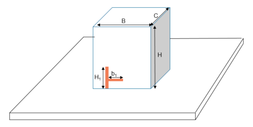
A DRA using a new probe double stub feeding strip and a parasitic patch has been proposed, as depicted in Figure 1. The antenna is modeled using the CST® Microwave Studio. The rectangular DRA (H = 26.1 mm, B= 25.4 mm, and C = 14.3 mm) with dielectric constant ε r = 10 is directly placed in the center of a ground plane (40 × 40 mm2). The feed connected to the exciting port is optimized with the double stub, while a parasitic patch is deployed at an optimized distance from the dual stub feed on the DRA surface. Electromagnetic coupling is used to excite the parasitic patch. The resonance frequency is controlled by optimizing the length, structure, and position of the feeding probe.
In the next section, the antenna design and optimization procedure to obtain a circularly polarized antenna is discussed in detail. The circularly polarized DRA’s performance excited by double stub feeding strip with and without the parasitic patch is explained and compared. Implementing a single DRA structure, several modes have been generated which produce multiple resonant frequencies. The proposed design is selected based on enhanced impedance and axial ratio bandwidths at the desired frequency band. The works done are motivated from previous design [27], where the initial size of the DRA is from the design.

2.1. Single Stub Feed DR Antenna (DRA1)

The rectangular DRA has been excited using a monopole with a stub feed placed on the rectangular DR side, as shown in Figure 2. The rectangular DR profile dimensions are H = 26.1 mm, B = 25.4 mm, and C = 14.3 mm, with the optimized feeding strip dimensions are H1 = 11 mm with a width of 1 mm, and b1 = 7.1 mm.
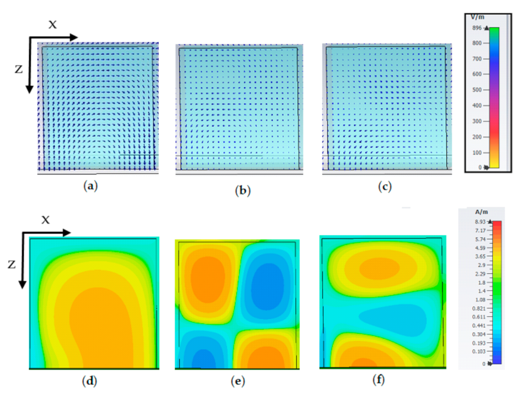
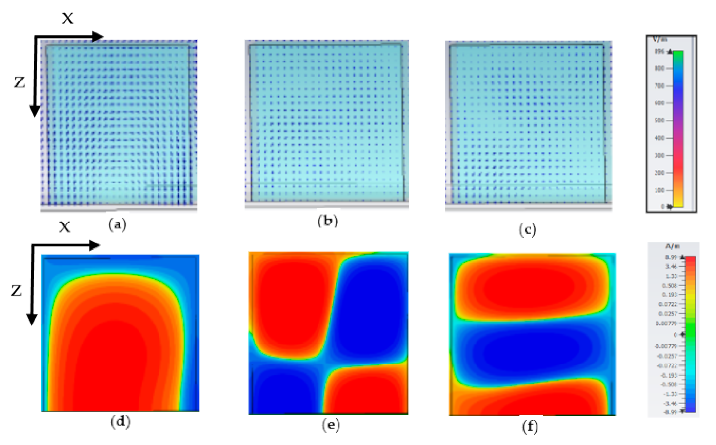
As presented in Figure 3a, the antenna resonates at multiple frequencies, which are 2.78 GHz (5.7%), 3.55 GHz (6.2%), 3.87 GHz (3.87%), and 5.47 GHz (3.1%). A circular polarization is achieved; however, the axial ratio (AR) did not match the resonance frequencies as depicted in Figure 3b. The degenerate mode pair of the fundamental mode T E 1 1 y has been excited at 3 GHz while T E 2 3 y and T E 1 5 y are excited at 4.9 GHz and 5.4 GHz, as depicted in Figure 4. The high order mode promotes the circularly polarized excitation in the antenna [8,9]. However, due to the small bandwidth and mismatched between AR and the S11, further improvement on the antenna is discussed in the next section.

2.2. Double Stub Feed DR Antenna (DRA2)

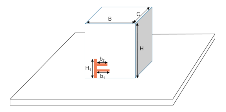
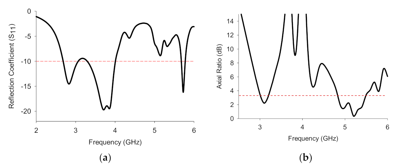
The antenna in Figure 2 is improved by adding 5.27 mm × 1 mm stub located on top of a single stub-shaped monopole (see Figure 5). It is improved by adding a 5.27 mm × 1 mm stub located on top of a single stub-shaped monopole (see Figure 5). This resulted from an improvement in the antenna operating frequency and impedance bandwidth. The antenna resonates at 2.82 GHz (13.13%), 3.8 GHz (18.4%), and 5.72 GHz (1.75%), as shown in Figure 6a. In contrast, the antenna’s AR occurs at 3.1 GHz (5.3%) and 5.2 GHz (12.15%), with minimum AR at 0.3 dB. The configuration exhibits fundamental mode at 3 GHz and higher-order mode T E 2 3 y and T E 1 5 y at 4.9 GHz and 5.4 GHz respectively, shown in Figure 7. Introducing double stubs in the design improved the S11 at 3 GHz but reduced the matching at 5 GHz. Additionally, the AR BW at 5 GHz was enhanced, as can be seen from the result shown in Figure 6b. Thus, further optimization on the design was carried on in the later section.

2.3. Double Stub Feed DR Antenna with Parasitic Patch (DRA3)

The optimized circularly polarized DRA has been excited in higher-order mode by feeding it with double stub and parasitic patch coupling at optimized lengths and widths, as illustrated in Figure 1. The parasitic patch increases the impedance match of the antenna as well as widening the bandwidth. The final dimension of the proposed antenna is given in Table 1. In the proposed DRA, it is found that both fundamental mode TE 11 x and higher-order mode TE 23 x were generated. The higher mode TE 23 x at 4.9 GHz and 5.4 GHz help in enhancing the circularly polarized bandwidth [11] and the gain of the antenna. Moreover, the higher-order mode has been excited using a low-cost, simple excitation mechanism without compromising on the size and shape of the DRA.
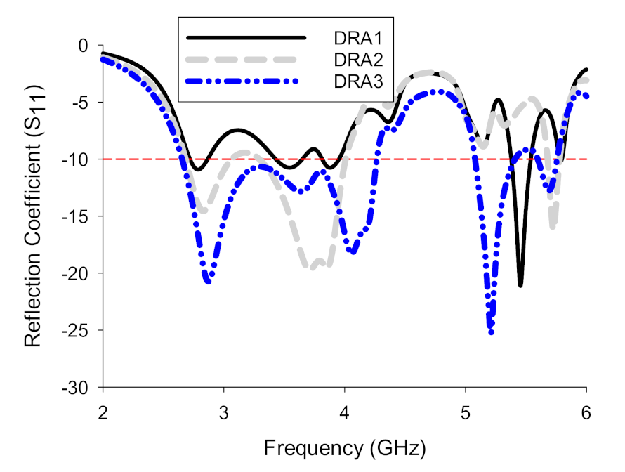
The result showed in Figure 8, where the dotted line gives the optimized design. The antenna resonates at three different frequencies: at 2.88 GHz with an impedance bandwidth of 1.6 GHz (46.24%), 5.2 GHz, and 5.69 GHz with bandwidth 6.3% and 2.5%, respectively. Adding parasitic elements at an optimized distance to the feed strip improved the antenna’s impedance matching and resulted in a wider bandwidth and operate in the higher mode,   TE 23 x . Comparing the optimized design to the previous method can be seen in Figure 8. The final design exhibits better impedance matching and broader bandwidth.
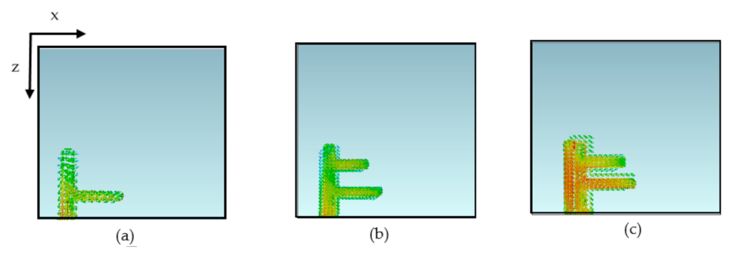
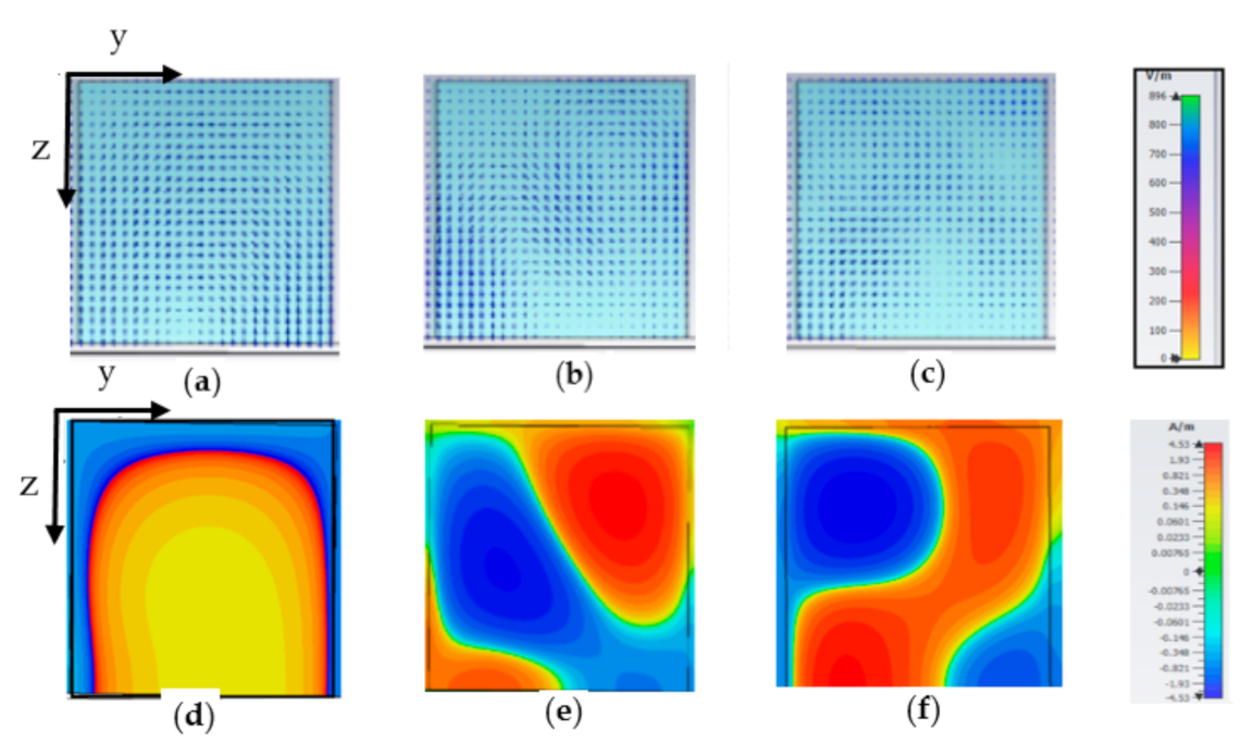
The intensity of current distribution for the DRA increases as the metal strip is added to the DRA, as illustrated in Figure 9. The proposed DRA exhibits the highest current distribution, which is indicated by the red color. The mode generated is depicted by Figure 10, fundamental mode TE 11 x is excited at 3 GHz and higher mode, TE 23 x excitation at 4.9 GHz and 5.4 GHz.
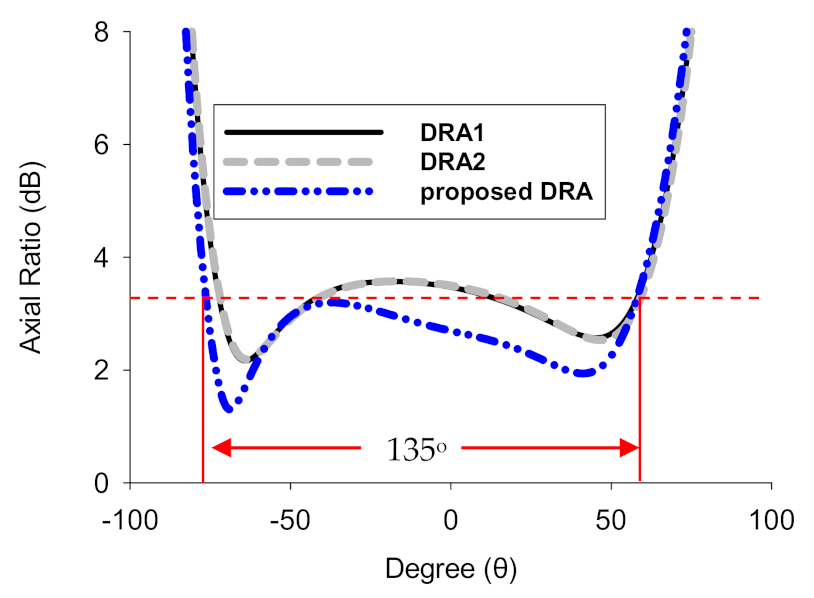
The variation of AR as a function of elevation angle is shown in Figure 11 at 3 GHz frequency. Comparing the three DRA configurations, the DRA1 and DRA2 have negative 23° and positive 30° of beamwidth, while the proposed DRA provide a wide beamwidth of circular polarization with ∼135° (−77° to 58°) in phi = 90° plane. On that account, the proposed CP DRA will have better signal reception as the wide beamwidth assist the antenna to receive signals uniformly over a wider range [28].

3. Measurement Results and Discussion

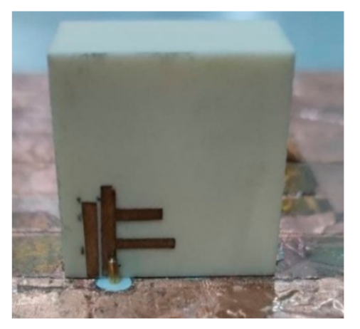
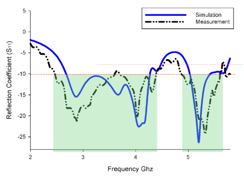
To verify the simulation, the optimized antenna design is fabricated and measured. The fabrication of the proposed CP DRA is shown in Figure 12. Reasonable agreement is achieved between simulation and measurement for resonance frequency, AR bandwidth, and the antenna’s gain. As can be seen in Figure 13, triple bands are obtained in the simulation. In contrast, in the measurement, a dual band is obtained with larger impedance bandwidth. A closed agreement between simulated and measured bandwidths of lower resonant frequency is achieved, of 46% (2.66–4.26 GHz) and 48% (2.43–4.35 GHz), respectively. In the upper band, a measured bandwidth of 13.3% (4.82–5.61 GHz) with 52.5% improvement from the simulated of the two upper bands. Both simulated and measured the reflection coefficient results showed a similar trend. However, some mismatch can be seen due to inaccuracy during the fabrication of the antenna. This also might be caused by the air gap between the DRA and the ground plane in the fabricated antenna compared to the one in simulation.
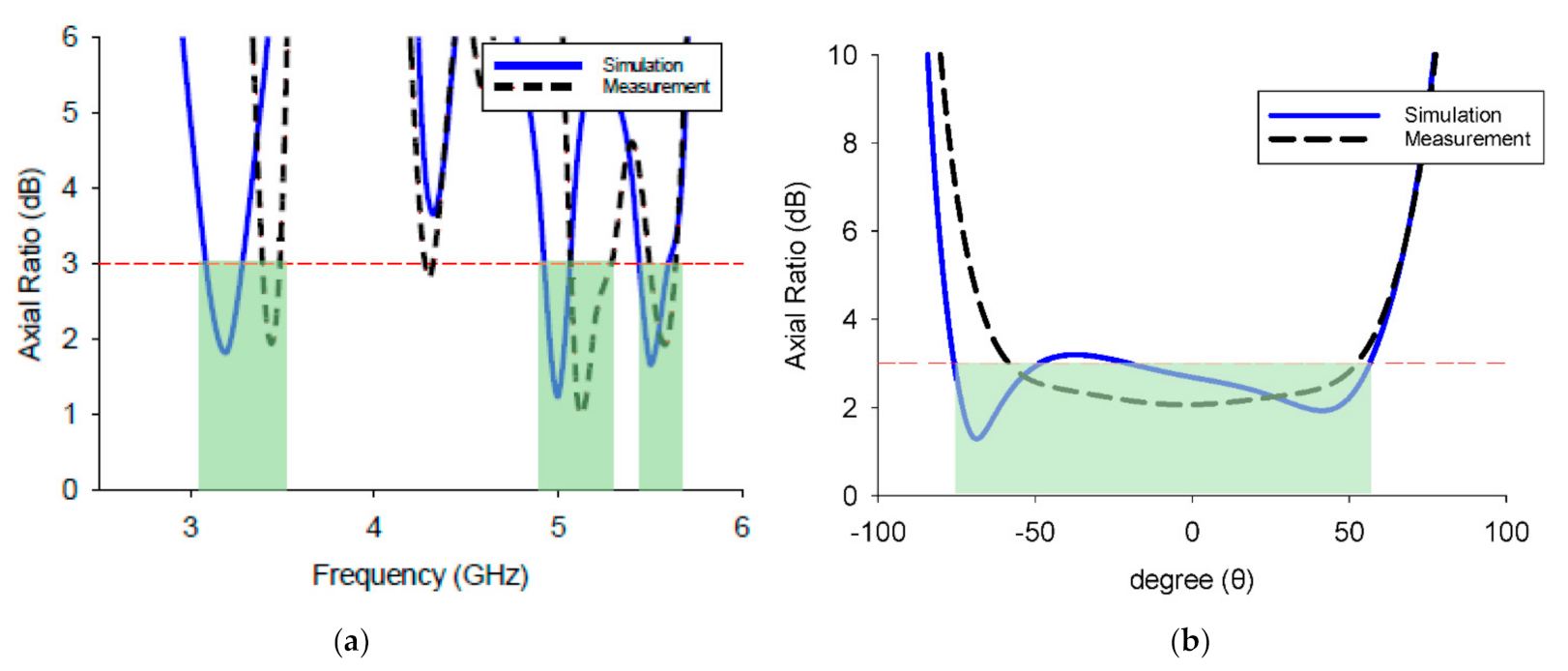
Axial ratio plots of the simulated and measured results are presented in Figure 14. It is found that the given axial ratio shows a good agreement between the simulations and measurements. The simulations resulted in a percentage bandwidth of 6.87%, 2.8%, and 2.9%, and the measured results are 3%, 4.5%, and 3.18%, respectively. Figure 14b showed that the beamwidth was compatible between simulated and measured results, although the measured beamwidth is 17% smaller than the simulated. The simulated and measured gains are plotted in Figure 15; both results show a good resemblance. The simulated gains of 5.38 dBic, 8.5 dBic, and 9.3 dBic is obtained at 3 GHz, 4.9 GHz, and 5.4 GHz. Simultaneously, the measured gain is 6.25 dBic, 9.44 dBic, and 9.3 dBic at the respective frequencies.
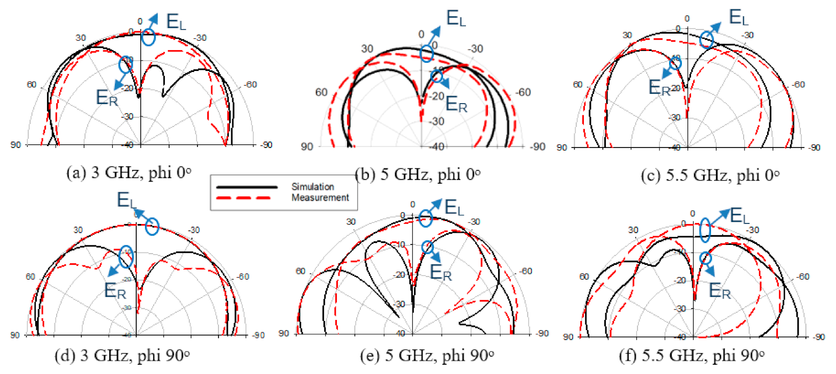
Radiation patterns of the proposed DRAs are studied by both simulation and measurements. Figure 16 shows radiation patterns of phi 0° dan 90° at 3, 4.9, and 5.4 GHz, respectively. It is found that the antenna is left-handed circularly polarized (LHCP), with the co-polar and cross-polar ratio of at least 20 dB. A comparative study on different approaches to generate CP using a DRA structure is presented in Table 2. The proposed DRA exhibits triple-band CP operation with the most considerable impedance bandwidth. Besides, there is a significant improvement in the obtained gain compared to the other literature. Additionally, the wide measured beamwidth of 112o promotes a better receiving signal over a wide range.

4. Conclusions

In summary, the proposed CP DRA with a microstrip patch coupled to the double stub feed structure could generate a tri-band CP antenna. The comparison was made to previous works on CP DRA, where it can conclude that the proposed CP DRA outperforms in terms of gain and the operational bandwidth by simple feeding structure. The combination of fundamental and higher-order mode excitation helps in enhancing the gain and bandwidth of the antenna. A bandwidth of 48% with a gain above 6 dBic was achieved in all resonance frequencies.

Author Contributions

Conceptualization, M.N.M.Y. and I.A.; methodology, M.N.M.Y.; software, M.N.M.Y.; validation, M.F.Z., J.I. and M.N.O.; formal analysis, I.A.; investigation, M.F.Z.; resources, M.F.Z.; writing—original draft preparation, I.A. and M.N.M.Y.; writing—review and editing, I.A. and M.N.O.; visualization, I.A.; supervision, J.I.; project administration, M.N.O.; funding acquisition, M.F.Z. and M.N.M.Y. All authors have read and agreed to the published version of the manuscript.

Funding

This research was funded by UNIVERSITI MALAYSIA PERLIS and Ministry of Higher Education, grant number FRGS/1/2020/ICT09/UNIMAP/02/2.

Institutional Review Board Statement

Not applicable.

Informed Consent Statement

Not applicable.

Acknowledgments

Authors would also like to thank all researchers of Antenna Research Centre, Faculty of Electrical Engineering, Universiti Teknologi MARA, Shah Alam, Selangor, Malaysia specifically Hadi Jumaat for his great assistance during measurement for supporting this project.

Conflicts of Interest

The authors declare no conflict of interest.

References

  1. Varshney, G.; Gotra, S.; Pandey, V.S.; Yaduvanshi, R.S. Inverted-Sigmoid Shaped Multiband Dielectric Resonator Antenna with Dual-Band Circular Polarization. IEEE Trans. Antennas Propag. 2018, 66, 2067–2072. [Google Scholar] [CrossRef]
  2. Li, B.; Leung, K.W. Strip-fed rectangular dielectric resonator antennas with/without a parasitic patch. IEEE Trans. Antennas Propag. 2005, 53, 2200–2207. [Google Scholar]
  3. Altaf, A.; Seo, M. Triple-band dual-sense circularly polarized hybrid dielectric resonator antenna. Sensors 2018, 18, 3899. [Google Scholar] [CrossRef] [Green Version]
  4. Yasin, M.N.M.; Khamas, S.K. Measurements and analysis of a probe-fed circularly polarized loop antenna printed on a layered dielectric sphere. IEEE Trans. Antennas Propag. 2012, 60, 2096–2100. [Google Scholar] [CrossRef]
  5. Mongia, R.K.; Ittipiboon, A. Theoretical and experimental investigations on rectangular dielectric resonator antennas. IEEE IEEE Trans. Antennas Propag. 1997, 45, 1348–1356. [Google Scholar] [CrossRef]
  6. Fang, X.; Leung, K.W.; Lim, E.H. Singly-Fed Dual-Band Circularly Polarized. IEEE Antennas Wirel. Propag. Lett. 2014, 13, 995–998. [Google Scholar] [CrossRef]
  7. Zou, M.; Pan, J. Wide Dual-Band Circularly Polarized Stacked Rectangular Dielectric Resonator Antenna. IEEE Antennas Wirel. Propag. Lett. 2016, 15, 1140–1143. [Google Scholar] [CrossRef]
  8. Illahi, U.; Iqbal, J.; Sulaiman, M.I.; Alam, M.; Su’ud, M.M.; Khattak, M.I. Design and development of a singly-fed circularly polarized rectangular dielectric resonator antenna for WiMAX/Satellite/5G NR band applications. AEU Int. J. Electron. Commun. 2020, 126, 153443. [Google Scholar] [CrossRef]
  9. Illahi, U.; Iqbal, J.; Sulaiman, M.I.; Alam, M.; Su’ud, M.M.; Jamaluddin, M.H. Singly-Fed Rectangular Dielectric Resonator Antenna with a Wide Circular Polarization Bandwidth and Beamwidth for WiMAX/Satellite Applications. IEEE Access 2019, 7, 66206–66214. [Google Scholar] [CrossRef]
  10. Illahi, U.; Iqbal, J.; Sulaiman, M.I.; Alam, M.; Su’ud, M.M.; Jamaluddin, M.H.; Yasin, M.A.M. Design of new circularly polarized wearable dielectric resonator antenna for off-body communication in WBAN applications. IEEE Access 2019, 7, 150573–150582. [Google Scholar] [CrossRef]
  11. Cheng, C.; Zhang, F.; Yao, Y.; Zhang, F. Triband Omnidirectional Circularly Polarized Dielectric Resonator Antenna with Top-Loaded Alford Loop. Int. J. Antennas Propag. 2014, 2014, 1–8. [Google Scholar] [CrossRef]
  12. Zhao, Z.; Ren, J.; Liu, Y.; Yin, Y. Wideband Dual-Feed, Dual-Sense Circularly Polarized Dielectric Resonator Antenna. IEEE Trans. Antennas Propag. 2020, 68, 7785–7793. [Google Scholar] [CrossRef]
  13. Ogurtsov, S.; Koziel, S.; Bekasiewicz, A. Axial ratio improvement of circular polarized dielectric resonator antennas with dual-point feeds. In Proceedings of the 2016 IEEE/ACES International Conference on Wireless Information Technology, ICWITS 2016 and System and Applied Computational Electromagnetics, ACES 2016—Proceedings, Honolulu, HI, USA, 13–18 March 2016; Volume 2, pp. 1–2. [Google Scholar]
  14. Wang, M.; Chu, Q.-X. A Wideband Polarization-Reconfigurable Water Dielectric Resonator Antenna. IEEE Antennas Wirel. Propag. Lett. 2019, 18, 402–406. [Google Scholar] [CrossRef]
  15. Chen, Z.; Wong, H. Liquid Dielectric Resonator Antenna with Circular Polarization Reconfigurability. IEEE Trans. Antennas Propag. 2018, 66, 444–449. [Google Scholar] [CrossRef]
  16. Abdulmajid, A.A.; Khalil, Y.; Khamas, S. Higher-order-mode circularly polarized two-layer rectangular dielectric resonator antenna. IEEE Antennas Wirel. Propag. Lett. 2018, 17, 1114–1117. [Google Scholar] [CrossRef]
  17. Altaf, A.; Jung, J.; Yang, Y.; Lee, K.-Y.; Hwang, K.C. ; Lee, K.-Y.; Hwang, K.C. Reconfigurable Dual- / Triple-Band Circularly Polarized Dielectric Resonator Antenna. IEEE Antennas Propag. Lett. 2020, 19, 443–447. [Google Scholar] [CrossRef]
  18. Gupta, A.; Gangwar, R.K. Dual-Band Circularly Polarized Aperture Coupled Rectangular Dielectric Resonator Antenna for Wireless Applications. IEEE Access 2018, 6, 11388–11396. [Google Scholar] [CrossRef]
  19. Liu, Y.; Jiao, Y.C.; Weng, Z.; Zhang, C.; Chen, G. A novel millimeter-wave dual-band circularly polarized dielectric resonator antenna. Int. J. Rf Microw. Comput. Eng. 2019, 29, 930–933. [Google Scholar] [CrossRef]
  20. Belen, M.A.; Mahouti, P.; Palandöken, M. Design and realization of novel frequency selective surface loaded dielectric resonator antenna via 3D printing technology. Microw. Opt. Technol. Lett. 2020, 62, 2004–2013. [Google Scholar] [CrossRef]
  21. Hayat, T.; Afzal, M.U.; Lalbakhsh, A.; Esselle, K.P. Additively manufactured perforated superstrate to improve directive radiation characteristics of electromagnetic source. IEEE Access 2019, 7, 153445–153452. [Google Scholar] [CrossRef]
  22. Adibi, S.; Honarvar, M.A.; Lalbakhsh, A. Gain enhancement of wideband circularly polarized UWB antenna using FSS. Radio Sci. 2021, 56. [Google Scholar] [CrossRef]
  23. Lalbakhsh, A.; Karu, P.E. Directivity improvement of a fabry-perot cavity antenna by enhancing near field characteristic. In Proceedings of the 2016 17th International Symposium on Antenna Technology and Applied Electromagnetics (ANTEM), Quebec, Canada, 10 July 2016; pp. 1–2. [Google Scholar]
  24. Lalbakhsh, A.; Muhammad, U.A.; Karu, P.E.; Stephanie, L.S. Low-cost nonuniform metallic lattice for rectifying aperture near-field of electromagnetic bandgap resonator antennas. IEEE Trans. Antennas Propag. 2020, 68, 3328–3335. [Google Scholar] [CrossRef]
  25. Sharma, A.; Sarkar, A.; Biswas, A.; Akhtar, M.J. A-shaped wideband dielectric resonator antenna for wireless communication systems and its MIMO implementation. Int. J. Rf Microw. Comput. Aided Eng. 2018, 28, e21402. [Google Scholar] [CrossRef]
  26. Abhishek, S.; Biswas, A. Wideband multiple-input–multiple-output dielectric resonator antenna. IET Microw. Antennas Propag. 2016, 11, 496–502. [Google Scholar]
  27. Iqbal, J.; Usman, I.; Sulaiman, M.I.; Alam, M.M.; Su’ud, M.M.; Yasin, M.N.M.; Jamaluddin, M.H. Bandwidth enhancement and generation of CP by using parasitic patch on rectangular DRA for wireless applications. IEEE Access 2019, 7, 94365–94372. [Google Scholar] [CrossRef]
  28. Jing, H.; Hao, W.; Ning, H.; Zong, Z. An X-band Wide Beamwidth CP Antenna Design with Extended Structure of Dielectric Substrate. In Proceedings of the 2019 International Applied Computational Electromagnetics Society Symposium—China (ACES), Nanjing, China, 8–11 August 2019; pp. 1–2. [Google Scholar]
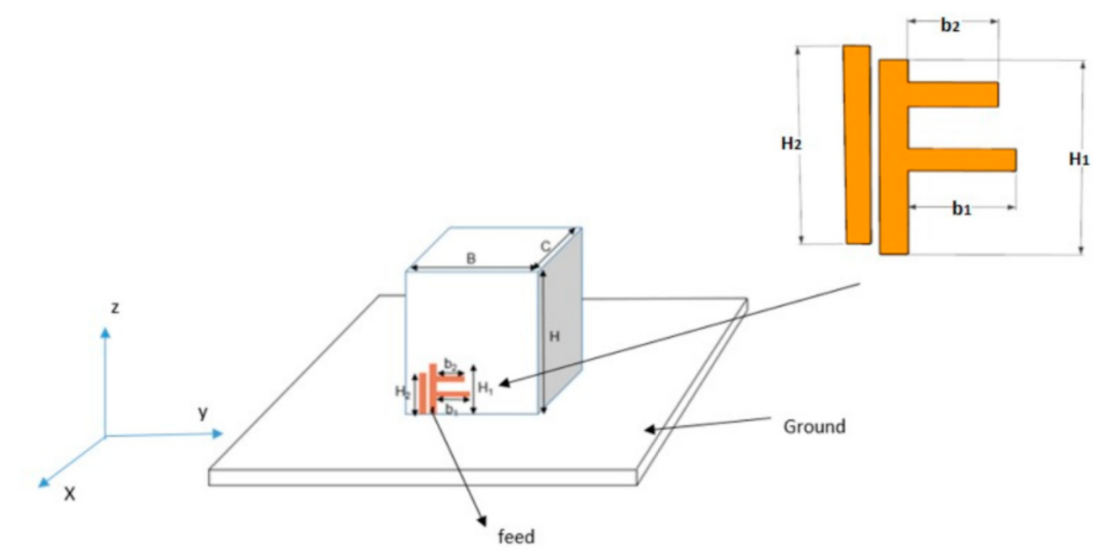
Figure 1. The proposed DRA antenna configuration.
Applsci 11 03493 g001
Figure 2. The initial proposed DR antenna with a single stub feed (DRA1).
Applsci 11 03493 g002
Figure 3. Result for a single stub DR antenna (DRA1). (a) Reflection coefficient and (b) axial ratio.
Applsci 11 03493 g003
Figure 4. The electric field of DRA1 (a) TE 1 1   y at 3 GHz, (b) TE 2 3 y at 4.9 GHz and (c) TE 1 5 y at 5.4 GHz. The magnetic field of DRA1 (d) TE 1 1   y at 3 GHz, (e) TE 2 3 y at 4.9 GHz and (f) TE 1 5 y at 5.4 GHz.
Applsci 11 03493 g004
Figure 5. The proposed double stub DRA (DRA2).
Applsci 11 03493 g005
Figure 6. Result for a double stub DR antenna (DRA2). (a) Reflection coefficient and (b) axial ratio.
Applsci 11 03493 g006
Figure 7. The electric field of DRA2 (a) TE 11 y at 3 GHz, (b) TE 2 3 y at 4.9 GHz and (c) TE 1 5 y at 5.4 GHz. The magnetic field of DRA2 (d) TE 11 y at 3 GHz, (e) TE 2 3 y at 4.9 GHz and (f) TE 1 5 y at 5.4 GHz.
Applsci 11 03493 g007
Figure 8. The comparison of the reflection coefficient for the proposed DRA.
Applsci 11 03493 g008
Figure 9. Current distribution of the DRA, (a) DRA1, (b) DRA2 and (c) the proposed DRA.
Applsci 11 03493 g009
Figure 10. The electric field of DRA3 (a) T E 11 x at 3 GHz, (b) T E 23 x at 4.9 GHz and (c) T E 23 x at 5.4 GHz. The magnetic field of DRA3 (d) T E 11 x at 3 GHz, (e) T E 23 x at 4.9 GHz and (f) T E 23 x at 5.4 GHz.
Applsci 11 03493 g010
Figure 11. Beamwidth of the proposed DRA at 3 GHz. θ
Applsci 11 03493 g011
Figure 12. The fabricate of the proposed CP DRA.
Applsci 11 03493 g012
Figure 13. Simulation and measurement reflection coefficient results of the proposed DRA.
Applsci 11 03493 g013
Figure 14. The axial ratio of simulated and measured of the proposed DRA. (a) AR versus frequency and (b) AR versus degree (θ).
Applsci 11 03493 g014
Figure 15. Simulated and measured gain of the proposed DRA.
Applsci 11 03493 g015
Figure 16. Simulated and measured radiation patterns of the proposed DRA.
Applsci 11 03493 g016
Table 1. The optimized DRA dimension.
ParameterDimension (mm)ParameterDimension (mm)
B25.4H111
C14.3H210.1
H26.1b17.1
b25.27
Table 2. Comparison of the previous works with the proposed DRA.
Ref No.Impedance BWs (GHz) (%)3 dB AR BWs (GHz) (%)Peak Gain (dBic)Size (λ0)
[3]1.71–2.03 [17.4]2.23–2.96 [28.13]3.65–3.76 [2.97]1.86–1.93 [3.96]2.67–2.82 [5.46]3.68–3.78 [2.15]55.282.360.44 × 0.5 × 0.16
[5]1.45–1.87 [25.3]2.1–3.0 [35.3]-1.53–1.63 [6.3]2.4–2.49 [3.68]-6.18.49--
[6]1.77–2.0 [12.2]2.38–2.96 [21.7]-1.76–1.94 [9.7]2.39–2.92 [20]-5.56.0--
[10]1.92–1.96 [1.55]2.32–2.50 [7.68]3.42–3.55 [3.87]1.93–1.96 [1.55]2.36–2.48 [4.96]3.50–3.53 [0.8]1.21.6−1.50.32 × 0.32 × 0.15
[16]2.12–2.45 [14.4]2.64–3.98 [40.5]-2.29–2.44 [6.34]2.76–2.95 [6.65]3.67–3.94 [7.09]4.55.385.75-
[17]3.4–3.58 [5.16]5.1–5.9 [14.55]-3.46–3.54 [2.28]5.18–5.34 [3.04]-5.15.15-0.47 × 0.47 × 0.11
Proposed2.43–4.35 [48]4.82–5.61 [14.8]-3.18–3.29 [3]4.88–5.18 [4.5]5.28–5.45 [3.18]6.29.449.30.3 × 0.29 × 0.16
Publisher’s Note: MDPI stays neutral with regard to jurisdictional claims in published maps and institutional affiliations.