Article

Torque Requirements and the Influence of Pilot Holes on Orthodontic Miniscrew Microdamage

1
Discipline of Orthodontics, University of Adelaide, Adelaide, SA 5000, Australia
2
Department of Paediatric Dentistry, Women’s and Children’s Hospital, North Adelaide, SA 5006, Australia
3
Discipline of Paediatric Dentistry, University of Adelaide, Adelaide, SA 5006, Australia
*
Author to whom correspondence should be addressed.
Appl. Sci. 2021, 11(8), 3564; https://doi.org/10.3390/app11083564
Submission received: 15 March 2021 / Revised: 11 April 2021 / Accepted: 12 April 2021 / Published: 15 April 2021
(This article belongs to the Special Issue Applied Biomaterials in Oral Surgery and Personalized Dentistry)

Abstract

:
This study aimed to quantify the microdamage to cortical bone of different thickness and the maximum insertion torque during orthodontic miniscrew implant (OMI) placement with and without a pilot hole. Forty-five porcine bone specimens were prepared with thicknesses of 1.5, 2 and 2.5 mm. Ten bone specimens per thickness had a pilot hole drilled prior to the insertion of an OMI, and the remaining 15 bone specimens had an OMI without a pilot hole inserted. Sequential staining was used to identify damage caused by bone preparation and surface microdamage from OMI insertion and confocal laser microscopy images were used to quantify damage characteristics. Of the five damage characteristics, only one decreased when a pilot hole was used for all bone specimens (p = 0.025), while two increased as cortical bone thickness increased (p = 0.0064, p = 0.0003). There was no evidence that maximum insertion torque differed according to pilot hole status (p = 0.1144) and increased as cortical bone thickness increased (p = 0.0001). The presence of a pilot hole had minimal effect on microdamage characteristics and no effect on maximum insertion torque. As cortical bone thickness increased, an increase in microdamage and in maximum insertion torque was observed.

1. Introduction

Absolute osseous anchorage using temporary anchorage devices (TADs) has expanded the possibilities of orthodontic tooth movement and decreased the requirement for patient compliance during treatment [1]. The most commonly used TADs are orthodontic miniscrew implants (OMIs). However, despite an increase in use since their introduction in the 1990s, the factors that lead to their failure remain poorly understood [2]. It has been suggested that the application of excessive torque during OMI insertion can cause damage to the surrounding bone, leading to premature failure [3,4,5]. Clinical and animal studies suggest that a pilot hole protocol prior to the insertion of an OMI may decrease insertion torque and microdamage, thereby improving the stability and success of OMIs [3,4,6,7,8,9,10]
The success of OMIs is defined as effective use for the required time during orthodontic treatment and, as with dental restorative implants, is dependent on primary stability (the mechanical interlock of the screw and bone, dependent on the quality and quantity of bone at the implant site) [11] and secondary stability (the biological process initiated after insertion of new bone growth and remodelling of bone around the implant) [12]. Microdamage from OMI insertion can cause failure of primary stability or an inflammatory process in the adjacent bone leading to loss of secondary stability [13,14]. Microdamage can be in the form of microcracks and diffuse damage in the bone surrounding the OMI [15]
Manufacturers may recommend a pilot hole predrill protocol to reduce tension and compression between the OMI and cortical bone during insertion. Cortical bone thickness generally ranges from 1.5 to 2.5 mm, and recommendations for a pilot hole are usually for areas where cortical bone is thicker, as found in the posterior mandible [16,17,18]. The risks of pilot hole insertion include additional surgical time, potential nerve damage, tooth root or germ damage, drill fracture and heat damage to the bone [19]. A technique described recently used sequential fluorochrome staining combined with laser confocal microscopy to allow visualisation of surface damage of cortical bone after insertion and removal of OMIs [20]. This technique was also used to visualise the clinically insignificant microdamage caused by a 0.9 mm pilot hole in varied cortical bone thicknesses [21]
To the authors’ knowledge, the histological difference in microdamage caused by OMI insertion with and without a pilot hole at different cortical bone thicknesses has not been previously quantified using a sequential fluorochrome staining and laser confocal microscopy approach. The specific aims were: (1) to quantify the microdamage to bone when an OMI is inserted with and without a pilot hole into cortical bone of different thickness; (2) to quantify the maximum insertion torque during OMI placement with and without a pilot hole, as cortical bone thickness changes; and (3) to determine the relationship between maximum insertion torque and microdamage to bone after placement of an OMI.

2. Materials and Methods

2.1. Bone Preparation

Four porcine tibia bones from different pigs were sourced from an abattoir (Golfland Butchers, Wingfield, Adelaide, SA, Australia). The University of Adelaide Ethics Committee confirmed that no ethics approval was required as the bones were sourced from animals slaughtered as part of routine commercial food production. The proximal and distal ends of each tibia bone were removed using a band saw as well as the soft tissue using a periosteal elevator, producing a clean bone surface.
Porcine bone specimens were prepared by a single operator (S.J.). Each bone was cut into three lengths of 20 mm using a band saw. A low-speed hard-tissue sectioning machine with a 6-inch diamond wafering blade (Allied High Tech Products Inc., Compton, CA, USA) was used to create 3–4 bone blocks from each length. Forty-five bone blocks with widths of 1.5, 2.0 or 2.5 mm were created by two parallel cuts along the cortex of the tibia bone. Copious water irrigation was used to maintain hydration of the specimens during sectioning.
Preparation of the bone block specimens introduced surface scratches which were removed using a wet polish with increasing grades of silicone carbide micromesh paper. Bone block specimens were immediately wrapped in phosphate-buffered saline solution-soaked gauze to maintain hydration and physical properties, then stored in a freezer at −23 °C until required. Experiments were performed within 2 months of bone block preparation.

2.2. Pilot Hole Creation

Ten bone blocks from each thickness group were randomly selected to receive a pilot hole. A custom acrylic clamp was designed to secure the bone block specimens to enable placement of the pilot hole at approximately 90 degrees to the bone surface. One pilot hole per bone block specimen was drilled by a single operator (S.J.) to the depth of the cortical bone thickness using a 0.9 mm pilot hole drill bit (MEDICON eG, Tuttlingen, Germany). A speed- and torque-controlled motor and handpiece (Elcomed, W&H Dentalwerk Bürmoos GmbH, Austria) was used to maintain the pilot hole drill at 200 rpm with continuous saline irrigation.

2.3. First Staining Sequence

All bone block specimens, with and without pilot holes, were immersed in a 0.5 mM aqueous xylenol orange solution for 30 min then rinsed with distilled water for 8 min. This stain was used to assess surface scratches and residual damage caused by sample preparation or pilot hole placement.

2.4. Orthodontic Miniscrew Implant Insertion

Bone blocks were returned to the custom acrylic clamp and insertion force was measured by a compression cell (Omega miniature compression load cell, R4-F6-76535; N2Surplus Inc., Roanoke, VA, USA) resting beneath the perspex clamp connected to a laptop running LabVIEW software (National Instruments Australia, Macquarie Park, NSW, Australia). Using a specialised torque- and speed-controlled handpiece capable of continuous torque measurement (Elcomed, W&H Dentalwerk Bürmoos GmbH, Burmoos, Austria), one OMI (1.5 × 6.0 mm Aarhus Anchor Mini-Implant (MEDICON eG, Tuttlingen, DE, USA)) was inserted until its neck contacted the bone surface of each bone block specimen. The maximum torque and time to insert the OMI were measured by the specialised handpiece. Data were produced directly onto a memory stick.

2.5. Second Staining Sequence

After OMIs were inserted, all bone block specimens were submerged in an aqueous solution of calcein 1 mM for 30 min, followed by an 8 min rinse with distilled water. This stain was used to assess the microdamage caused by the insertion of the OMI.

2.6. Orthodontic Miniscrew Implant Removal

All bone block specimens were placed back into the customised acrylic clamp for removal of the OMIs using the same speed and torque-controlled handpiece.

2.7. Third Staining Sequence

The specimens were submerged in calcein blue 1 mM for 30 min, followed by an 8 min rinse with distilled water. This stain was used to assess the microdamage caused by removal of the OMI.

2.8. Microscopic Analysis

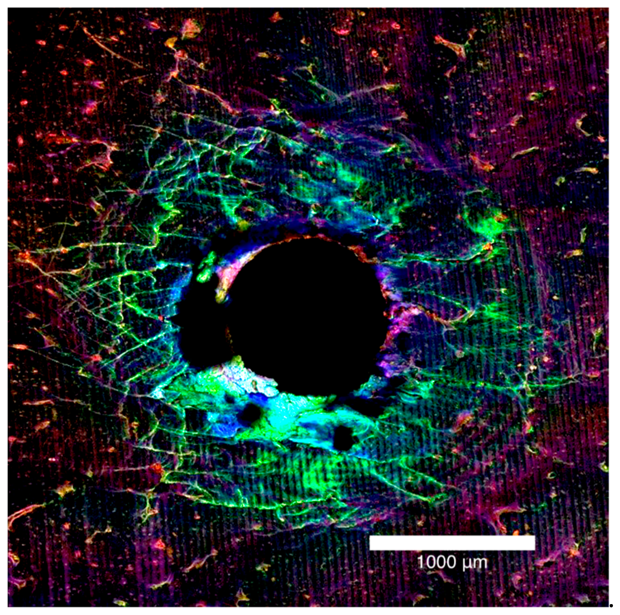
The bone block specimens were imaged on both the entry and exit surfaces with an Olympus FV3000 confocal laser scanning microscope (Olympus Australia Pty Ltd., Notting Hill, VIC, Australia). To excite and subsequently fluoresce the xylenol, calcein and calcein blue 561DPSS (569–700 nm red spectrum), 488 argon (496–593 nm green spectrum) and 405 diode (413–480 nm blue spectrum) lasers were used (Figure 1a–c). The surfaces were imaged to a depth of 200 µm at 10 µm intervals. A composite view of the microdamage to 200 µm was achieved by stacking the images together (Figure 2).
The microdamage measurements were recorded as diffuse damage and linear microcracks. Diffuse damage was defined as localised intense bone deformation and small cracks that overlap each other and microcracks were defined as cracks extending more than 100 µm into the bone [22]. These microdamage metrics were recorded in millimetres and quantitative measurements were made using the ImageJ (National Institutes of Health, Bethesda, MD, USA) program for total damage area, diffuse damage area, maximum damage radius, maximum diffuse damage radius and maximum crack length in mm2 (Figure 3).

2.9. Statistical Analyses

Statistical analyses were conducted using Stata (Version 15, Stata Corp, College Station, TX, USA). Summary statistics (mean, standard deviation) for OMI characteristics and bone damage measures were obtained for groups defined by pilot hole status (present or absent) and bone thickness group (1.5, 2.0 and 2.5 mm). Data for entry and exit surfaces of the bone were combined. Pearson correlations were used to assess the association between OMI insertion torque and each of the bone damage characteristics. For all analyses, the level of statistical significance was set to 0.05.

3. Results

3.1. Microdamage and Pilot Hole

The characteristics of the OMI insertion (time to drill and average drill force), and measures of bone damage were combined for the three bone thickness groups (Table 1). Maximum crack length was significantly reduced when a pilot hole was used (p = 0.025). The other damage characteristics did not produce a significant change.

3.2. Microdamage and Bone Thickness

Summary statistics were calculated for bone damage characteristics according to both pilot hole status and bone thickness (Table 2). There was strong evidence for an interaction between pilot hole status and bone thickness for total damage area (p = 0.0064) and diffuse damage area (p = 0.0003). There was no evidence that bone thickness had a significant effect on the maximum damage radius, maximum diffuse damage radius or maximum crack length.

3.3. Maximum Insertion Torque and Pilot Hole

There was no evidence that maximum insertion torque differed according to pilot hole status. There was an estimated 1.71 Ncm increase in maximum insertion torque when a pilot hole was present (95% CI (0.43, 3.85) p = 0.1144).

3.4. Maximum Insertion Torque and Bone Thickness

There was evidence to suggest that maximum insertion torque differed between thickness groups (p-value = 0.0001). Keeping pilot hole status constant, maximum insertion torque increased with increasing bone thickness (Figure 4). Maximum insertion torque was on average 3.92 Ncm higher for 2.0 mm bone specimens compared to 1.5 mm bone specimens (95% (CI 1.45, 6.39) p = 0.003), and 5.94 Ncm higher in the 2.5 mm bone compared to the 1.5 mm bone (95% CI [3.47, 8.41] p < 0.0001). There was little evidence that the maximum insertion torque differed between the 2.0 and 2.5 mm bone block specimens (95% CI (0.45, 4.49) p = 0.107).

3.5. Maximum Insertion Torque and Microdamage

Pearson’s pairwise correlations between maximum insertion torque and each of the damage characteristics were calculated. There was an association between the maximum insertion torque and total damage area (r = 0.49, p < 0.001). Maximum insertion torque was also associated with diffuse damage area (r = 0.31, p = 0.04).

4. Discussion

Four of the five damage characteristics showed no reduction in microdamage when a pilot hole was drilled. There was a significant decrease in maximum crack length, but the difference was small and may not hold clinical significance. These findings differ from an in vitro canine study that found less microdamage for 2.2 mm cortical bone when a pilot hole was used [9]. Similarly, a further canine study showed reduced microdamage when a pilot hole was pre-drilled [23]; however, bone specimens were prepared for analysis after insertion of OMIs and for which preparation damage was not controlled.
Reductions in all damage characteristics were observed as cortical bone thickness decreased. The reduced microdamage with decreasing cortical bone thickness may be explained by fewer threads of the OMI engaging with the cortical bone [20]. The OMIs used in this study had a thread pitch (distance between threads) of 0.685 mm, and fewer threads were embedded in the bone as the thickness decreased by 0.5 mm increments [24]. Another study found no correlation between cortical bone thickness and microdamage when an Aarhus 1.5 mm diameter OMI was inserted into porcine bone [13]; however, the reported study evaluated microdamage using scanning electron microscopy, which potentially introduced cracks from sample dehydration.
There was no difference in maximum insertion torque according to pilot hole status, which confirms the findings of previous research [25]. Insertion torque increased with the depth of insertion, with the maximum insertion torque occurring at the end of OMI insertion as the neck of the screw comes into contact with the bone [11]. In the present study, the OMIs were inserted to a maximum depth, at which point the neck of the OMI made contact with bone, to ensure complete insertion, regardless of pilot hole status. This contradicts the findings of Suzuki and Suzuki [5] and Chen et al. [17], who reported a decrease of 20–40% in maximum insertion torque when a pilot hole protocol was used. Clinically, it is difficult to determine the depth of insertion due to the variation in overlying soft tissue thickness. These other studies did not account for the confounding factor of OMI insertion depth, which would be difficult to control in vivo due to the soft tissues.
The present study clearly found an increase in maximum insertion torque as cortical bone thickness increased. This confirms the findings of a study that measured maximum insertion torque during OMI insertion into 1.5 and 2.0 mm artificial cortical bone [26]. These findings are relevant for clinicians inserting OMIs into thicker cortical bone, found in the posterior mandible, where the maximum insertion torque will increase. In addition, higher maximum insertion torque was related to increased microdamage characteristics, specifically total damage area and diffuse damage area. As previous studies found that maximum insertion torque is related to lower OMI success rates [3,4], this may be explained by an increase in microdamage created during OMI insertion. A survey of orthodontic practitioners who measured insertion torque during placement of OMIs had greater overall success rates compared to those who did not measure torque [27]
Porcine bone has been used in previous studies for the detection of microdamage and OMI torque measurements [6,20,28], but it is likely that the cortical bone of the maxilla and mandible behaves differently to that of porcine tibia bone [29,30,31]. However, the availability and ease of sample preparation with fresh porcine bone make it an ideal experimentation model. Future research to validate the use of porcine bone as a model for human cortical bone would be beneficial to support the clinical applicability of the present results.

5. Conclusions

The presence of a pilot hole had minimal effect on microdamage characteristics and minimal effect on maximum insertion torque. As cortical bone thickness increased, greater microdamage and an increase in maximum insertion torque was observed. The clinical significance of a reduction in damage characteristics may not outweigh the significant risks involved in a predrill pilot hole protocol. Therefore, clinical judgement should be employed regarding the thickness of cortical bone that requires a pilot hole.

Author Contributions

Conceptualization, S.W.J., W.S. and C.D.; methodology, S.W.J.; software, S.W.J.; writing—original draft preparation, E.D.J.; writing—review and editing, S.W.J., W.S. and C.D.; funding acquisition, S.W.J. All authors have read and agreed to the published version of the manuscript.

Funding

This research was funded by the Australian Society of Orthodontists, Foundation for Research and Education.

Institutional Review Board Statement

Ethical review and approval were waived for this study, due to the bones were sourced from animals slaughtered as part of routine commercial food production.

Informed Consent Statement

Not applicable.

Data Availability Statement

Data is contained within the article.

Acknowledgments

The authors thank Jana Bednarz, (Adelaide Health and Technology Assessment, School of Public Health, University of Adelaide), for assisting with statistical analysis and interpretation of the data. The authors acknowledge the facilities, scientific and technical assistance from the Australian Microscopy and Microanalysis Research Facility, University of Adelaide.

Conflicts of Interest

The authors declare no conflict of interest.

References

  1. Jacobson, A. Mini-implants in Orthodontics: Innovative Anchorage Concepts. Am. J. Orthod. Dentofac. Orthop. 2009, 136, 471–472. [Google Scholar] [CrossRef]
  2. Kanomi, R. Mini-implant for Orthodontic Anchorage. J. Clin. Orthod. JCO 1997, 31, 763. [Google Scholar]
  3. Motoyoshi, M.; Hirabayashi, M.; Uemura, M.; Shimizu, N. Recommended Placement Torque When Tightening an Orthodontic Mini-implant. Clin. Oral Implant. Res. 2006, 17, 109–114. [Google Scholar] [CrossRef] [PubMed]
  4. Motoyoshi, M.; Matsuoka, M.; Shimizu, N. Application of Orthodontic Mini-implants in Adolescents. Int. J. Oral Maxillofac. Surg. 2007, 36, 695–699. [Google Scholar] [CrossRef]
  5. Suzuki, E.Y.; Suzuki, B. Placement and Removal Torque Values of Orthodontic Miniscrew Implants. Am. J. Orthod. Dentofac. Orthop. 2011, 139, 669–678. [Google Scholar] [CrossRef] [PubMed]
  6. Wilmes, B.; Drescher, D. Impact of Bone Quality, Implant Type, and Implantation Site Preparation on Insertion Torques of Mini-implants Used for Orthodontic Anchorage. Int. J. Oral and Maxillofac. Surg. 2011, 40, 697–703. [Google Scholar] [CrossRef]
  7. Wilmes, B.; Rademacher, C.; Olthoff, G.; Drescher, D. Parameters Affecting Primary Stability of Orthodontic Mini-implants. J. Orofac. Orthop. 2006, 67, 162–174. [Google Scholar] [CrossRef] [PubMed]
  8. Di Lello, F.P.; Sgarbi, F.R.V.S.; Boeck, E.M.; Lunardi, N.; Neto, R.J.B. Effect of Angled Installation of Orthodontic Mini-implants on Primary Stability. J. Res. Dent. 2014, 2, 169–175. [Google Scholar] [CrossRef] [Green Version]
  9. Shank, S.B.; Beck, F.M.; D’Atri, A.M.; Huja, S.S. Bone Damage Associated with Orthodontic Placement of Miniscrew Implants in an Animal Model. Am. J. Orthod. Dentofac. Orthop. 2012, 141, 412–418. [Google Scholar] [CrossRef]
  10. Wilmes, B.; Su, Y.-Y.; Drescher, D. Insertion Angle Impact on Primary Stability of Orthodontic Mini-implants. Angle Orthod. 2008, 78, 1065–1070. [Google Scholar] [CrossRef]
  11. Wilmes, B.; Drescher, D. Impact of Insertion Depth and Predrilling Diameter on Primary Stability of Orthodontic Mini-implants. Angle Orthod. 2009, 79, 609–614. [Google Scholar] [CrossRef]
  12. Reynders, R.A.M.; Ronchi, L.; Ladu, L.; van Etten-Jamaludin, F.; Bipat, S. Insertion Torque and Success of Orthodontic Mini-implants: A Systematic Review. Am. J. Orthod. Dentofac. Orthop. 2012, 142, 596–614.e5. [Google Scholar] [CrossRef] [PubMed]
  13. Wawrzinek, C.; Sommer, T.; Fischer-Brandies, H. Microdamage in Cortical Bone Due to the Overtightening of Orthodontic Microscrews. J. Orofac. Orthop. 2008, 69, 121–134. [Google Scholar] [CrossRef]
  14. Çehreli, S.; Arman-Özçırpıcı, A. Primary Stability and Histomorphometric Bone-implant Contact of Self-drilling and Self-tapping Orthodontic Microimplants. Am. J. Orthod. Dentofac. Orthop. 2012, 141, 187–195. [Google Scholar] [CrossRef] [PubMed]
  15. Lee, T.C.; Mohsin, S.; Taylor, D.; Parkesh, R.; Gunnlaugsson, T.; O’Brien, F.J.; Giehl, M.; Gowin, W. Detecting Microdamage in Bone. J. Anat. 2003, 203, 161–172. [Google Scholar] [CrossRef] [PubMed]
  16. Ellis, J.A.; Laskin, D.M. Analysis of Seating and Fracturing Torque of Bicortical Screws. J. Oral Maxillofac. Surg. 1994, 52, 483–486. [Google Scholar] [CrossRef]
  17. Chen, Y.; Shin, H.-I.; Kyung, H.-M. Biomechanical and Histological Comparison of Self-drilling and Self-tapping Orthodontic Microimplants in Dogs. Am. J. Orthod. Dentofac. Orthop. 2008, 133, 44–50. [Google Scholar] [CrossRef]
  18. Baumgaertel, S.; Hans, M.G. Buccal Cortical Bone Thickness for Mini-implant Placement. Am. J. Orthod. Dentofac. Orthop. 2009, 136, 230–235. [Google Scholar] [CrossRef] [PubMed]
  19. Gupta, N.; Kotrashetti, S.; Naik, V. A Comparitive Clinical Study between Self Tapping and Drill Free Screws as a Source of Rigid Orthodontic Anchorage. J. Maxillofac. Oral Surg. 2012, 11, 29–33. [Google Scholar] [CrossRef] [PubMed] [Green Version]
  20. Nguyen, M.V.; Codrington, J.; Fletcher, L.; Dreyer, C.W.; Sampson, W.J. Influence of Cortical Bone Thickness on Miniscrew Microcrack Formation. Am. J. Orthod. Dentofac. Orthop. 2017, 152, 301–311. [Google Scholar] [CrossRef] [PubMed]
  21. Jensen, S.W.; Jensen, E.D.; Sampson, W.J.; Dreyer, C.W. Assessment of Microdamage Caused by Orthodontic Miniscrew Pilot Holes. Australas. Orthod. J. 2020, 36, 146. [Google Scholar]
  22. Martin, R. Fatigue Microdamage as an Essential Element of Bone Mechanics and Biology. Calcif. Tissue Int. 2003, 73, 101–107. [Google Scholar] [CrossRef]
  23. Yadav, S.; Upadhyay, M.; Liu, S.; Roberts, E.; Neace, W.P.; Nanda, R. Microdamage of the Cortical Bone during Mini-implant Insertion with Self-drilling and Self-tapping Techniques: A Randomized Controlled Trial. Am. J. Orthod. Dentofac. Orthop. 2012, 141, 538–546. [Google Scholar] [CrossRef] [PubMed]
  24. Katić, V.; Kamenar, E.; Blažević, D.; Špalj, S. Geometrical Design Characteristics of Orthodontic Mini-implants Predicting Maximum Insertion Torque. Korean J. Orthod. 2014, 44, 177–183. [Google Scholar] [CrossRef] [PubMed] [Green Version]
  25. Son, S.; Motoyoshi, M.; Uchida, Y.; Shimizu, N. Comparative Study of the Primary Stability of Self-drilling and Self-tapping Orthodontic Miniscrews. Am. J. Orthod. Dentofac. Orthop. 2014, 145, 480–485. [Google Scholar] [CrossRef] [PubMed]
  26. Song, Y.-Y.; Cha, J.-Y.; Hwang, C.-J. Mechanical Characteristics of Various Orthodontic Mini-screws in Relation to Artificial Cortical Bone Thickness. Angle Orthod. 2007, 77, 979–985. [Google Scholar] [CrossRef] [PubMed]
  27. Buschang, P.H.; Carrillo, R.; Ozenbaugh, B.; Rossouw, P.E. 2008 Survey of AAO Members on Miniscrew Usage. J. Clin. Orthod. JCO 2008, 42, 513. [Google Scholar] [PubMed]
  28. Nguyen, M.V.; Codrington, J.; Fletcher, L.; Dreyer, C.W.; Sampson, W.J. The Influence of Miniscrew Insertion Torque. Eur. J. Orthod. 2018, 40, 37–44. [Google Scholar] [CrossRef] [PubMed]
  29. Oltramari, P.V.; Navarro, R.L.; Henriques, J.F.; Capelozza, A.L.; Granjeiro, J.M. Dental and Skeletal Characterization of the BR-1 Minipig. Vet. J. 2007, 173, 399–407. [Google Scholar] [CrossRef] [PubMed]
  30. Boutrand, J.-P. Biocompatibility and Performance of Medical Devices; Elsevier: Amsterdam, The Netherlands, 2012. [Google Scholar]
  31. Zimmermann, C.; Thurmüller, P.; Troulis, M.J.; Perrott, D.H.; Rahn, B.; Kaban, L.B. Histology of the Porcine Mandibular Distraction Wound. Int. J. Oral Maxillofac. Surg. 2005, 34, 411–419. [Google Scholar] [CrossRef]
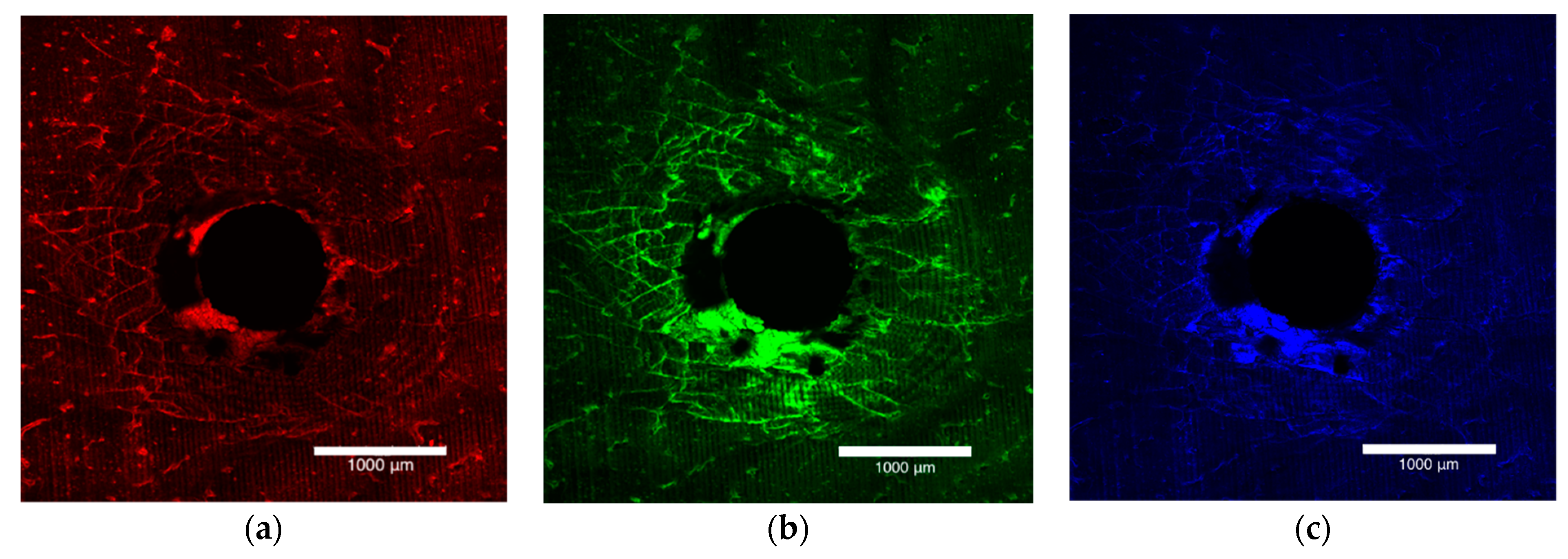
Figure 1. Laser confocal microscope images depicting the entry surface of a 2.0 mm thickness bone block specimen. (a) The orange flecks represent the surface preparation damage, (b) the green stain highlights the damage caused by insertion of the OMI and (c) the blue stain outlines the damage caused by removal of the OMI.
Applsci 11 03564 g001
Figure 2. Laser confocal microscope images presented in Figure 1, stacked together to form a composite view of the entry surface of a 2.0 mm bone block specimen.
Applsci 11 03564 g002
Figure 3. Laser confocal microscope composite image of the entry surface of a 2.0 mm thick bone block specimen (1) total damage area, (2) diffuse damage area, and mm for (3) maximum damage radius, (4) maximum diffuse damage radius, (5) maximum crack length.
Applsci 11 03564 g003
Figure 4. Box plot of maximum insertion torque (Ncm) comparing no pilot hole (NoPH) to pilot hole (PH) for each bone thickness.
Applsci 11 03564 g004
Table 1. Characteristics of bone block specimens of combined thicknesses with and without a pilot hole drilled prior to insertion of the orthodontic miniscrew implant (OMI).
CharacteristicNo Pilot Hole
(n = 15)
Pilot Hole
(n = 30)
OMI INSERTION
Insertion time (s)28.77 ± 2.0717.43 ± 2.80
Average insertion force (N)22.08 ± 2.2517.02 ± 4.74
Max insertion torque (Ncm)19.67 ± 3.8621.38 ± 4.19
DAMAGE CHARACTERISTICS Differencep-value
Total damage area (mm2)4.77 ± 1.805.60 ± 1.320.830.085
Diffuse damage area (mm2)3.40 ± 1.263.34 ± 1.04−0.050.879
Max damage radius (mm)1.96 ± 0.491.82 ± 0.34−0.140.272
Max diffuse damage radius (mm)1.32 ± 0.271.26 ± 0.27−0.070.447
Max crack length (mm)1.62 ± 0.461.34 ± 0.35−0.280.025 *
* p < 0.05.
Table 2. Observed mean and standard deviation for each damage characteristic according to pilot hole status and bone thickness.
No Pilot HolePilot Hole
Damage Characteristics1.5 mm
(n = 5)
2.0 mm
(n = 5)
2.5 mm
(n = 5)
1.5 mm
(n = 10)
2.0 mm
(n = 10)
2.5 mm
(n = 10)
Total damage area (mm2)4.45 ± 1.864.55 ± 1.765.30 ± 1.834.98 ± 1.075.79 ± 1.126.03 ± 1.53
Diffuse damage area (mm2)3.52 ± 1.503.24 ± 1.323.43 ± 1.042.76 ± 0.753.54 ± 0.883.72 ± 1.21
Max damage radius (mm)2.12 ± 0.661.78 ± 0.361.99 ± 0.391.66 ± 0.241.92 ± 0.341.89 ± 0.36
Max diffuse damage radius (mm)1.35 ± 0.391.33 ± 0.251.30 ± 0.151.15 ± 0.311.28 ± 0.201.34 ± 0.25
Max crack length (mm)1.66 ± 0.621.49 ± 0.291.72 ± 0.431.22 ± 0.261.43 ± 0.321.37 ± 0.42
Publisher’s Note: MDPI stays neutral with regard to jurisdictional claims in published maps and institutional affiliations.