Article

Training and Inference of Optical Neural Networks with Noise and Low-Bits Control

1
School of Automation, Beijing Information Science and Technology University, Beijing 100192, China
2
Institute of Semiconductors, Chinese Academy of Sciences, Beijing 100083, China
3
College of Materials Science and Opto-Electronic Technology, University of Chinese Academy of Sciences, Beijing 100049, China
*
Authors to whom correspondence should be addressed.
Appl. Sci. 2021, 11(8), 3692; https://doi.org/10.3390/app11083692
Submission received: 30 March 2021 / Revised: 8 April 2021 / Accepted: 12 April 2021 / Published: 20 April 2021
(This article belongs to the Collection Optical Design and Engineering)

Abstract

:
Optical neural networks (ONNs) are getting more and more attention due to their advantages such as high-speed and low power consumption. However, in a non-ideal environment, the noise and low-bits control may heavily lead to a decrease in the accuracy of ONNs. Since there is AD/DA conversion in a simulated neural network, it needs to be quantified in the model. In this paper, we propose a quantitative method to adapt ONN to a non-ideal environment with fixed-point transmission, based on the new chip structure we designed previously. An MNIST hand-written data set was used to test and simulate the model we established. The experimental results showed that the quantization-noise model we established has a good performance, for which the accuracy was up to about 96%. Compared with the electrical method, the proposed quantization method can effectively solve the non-ideal ONN problem.

1. Introduction

With the explosion of information, more data need to be processed. The neural network is considered to be a promising candidate for bulk information processing [1]. Thus far, we have many optimization methods and non-iterative linear supervised learning predictors that can improve computing power, such as multilayer perceptron, support vector machines, and neural-like structures of the successive geometric transformations model (SGTM) [2]. In recent years, optical neural networks (ONNs) have gained a large amount of attention due to their high-speed, low power consumption, and low delay [3,4,5,6]. It has been shown that matrix multiplication and parameterization can be obtained on an optical neural network made by Mach–Zehnder interferometer (MZI) arrays [7,8,9].
With the development of ONNs, some important issues have occurred in the non-ideal case, which may reduce the accuracy of the optical neural network. Therefore, these issues need to be understood deeply. In practice, the following conditions may increase the error of the optical device. One is the phase shift generated by optical devices, which cannot achieve arbitrary precision in physics [3,4,10,11]. The other is quantum-limit noise on optical devices [10,11,12]. Up to now, the goal of large-scale, rapidly reprogrammable photonic neural networks has not been realized. There are still plenty of opportunities for improving ONNs [13,14]. Processing large amounts of data remain challenging for ONNs for computer vision in real life.
Most research on ONN has focused on different types of devices and novel architectures, while limited work has been undertaken on the impact of noise problems on accuracy in photonic chips. Several groups have begun to study these issues. In 2017, Yichen Shen’s chip implemented a neural network that can recognize four basic vowels [3]. In 2019, Ryan Hamerly presented a new type of photon accelerator based on coherence detection capabilities [4]. They also simulated noise in this device. Other papers propose a noise perception quantization scheme to help design a robust ONN model [10]. The above work illustrates that ONN architecture requires special hardware implementation and, ideally, low-bit control.
In this paper, based on the new chip structure we designed previously [15], a noise quantization model is proposed to analyze the influence of quantization on the accuracy of ONNs, so as to make it closer to reality. We also optimize the algorithm so that the chips that are run in real conditions can achieve high precision. A method that solves ONNs’ low-bit control and simulation on devices is proposed for the first time.

2. Architecture

2.1. Neural Networks and ONNs

A fully connected neural network consists of an input layer, hidden layers, and an output layer, as shown in Figure 1 [16]. The image of the handwritten data set (MNIST [17]) is input into the network for simulation [18]. Since the handwritten data set is composed of 0–9, the output layer has 10 outputs.
In our previous work [15], we designed an image classification and recognition model based on a fully connected neural network (FCNN) and mapped it to a silicon-based photonic integrated circuit, as shown in Figure 2 [15]. Previous simulation experiments showed that the optical modulator enabled the chip to perform fast and high-precision classification of hand-written numbers with an accuracy greater than 97%. Speeds of up to 80 Gbps can be achieved at the currently reported rates of silicon-based modulators. Up to 80 Gbps can be achieved in the recently reported rates of silicon-based modulators.
A silicon ONN chip is mainly composed of five parts. In the first part of Figure 2a, the input port can be realized by a side coupler or grating coupler. The fan-out structure can be realized by cascading 1 × 2 multi-mode interference (MMI). The second part is the input light divided into 128 parts, with one Mach–Zehnder modulator (MZM) for every two channels. The third part consists of 256 MZMs, half of which are used to encode the target file and the other half to load the weight signal. Then, two waveguides, a silicon waveguide and a sinusoidal waveguide, are used to realize the matching structure of the target file signal and the weight signal. In the fourth part, there are 128 balance detectors, each of which multiplies the one-way target file signal with the weight signal. The final addition and activation functions can be implemented via circuits, which are composed of the fifth part.
The ONN chip is designed to recognize 10 complete (0 to 9) handwritten digital images simultaneously. We resize the digital images into 11 × 11 grayscale matrices with 8-bit resolution and flatten them into vectors. These vectors are fed through parts one and two, and are multiplexed in the time domain. Next, in the third and fourth part, the pairing of the encoded target file and the loaded weight signal and the multiplicative accumulation operations are performed. Finally, different node/neuron outputs are obtained by sampling the results of the previous step. The final output of the ONN is represented by the intensity of the output neurons, with the highest intensity of each test image corresponding to the prediction category. The peripheral system, including signal sampling, nonlinear functions, and merging, is implemented electronically by means of digital signal processing hardware.
Figure 3 shows the schematic diagram of the optoelectronic system. After being input through the input port, the signal is multiplied and added by the optical neural network chip, and output through the balance detector. Shot noise is generated in the balanced detector. The balanced detector enters the circuit through AD/DA conversion, and the computer is used to process the data in the nonlinear part. In this part, quantization of the data is required. Since the optical neural network we designed has three layers, this process needs to be cycled three times to get the final output. We will elaborate on the specific models for noise and quantization in the following sections.
The power consumption of this ONN chip comes mainly from the modulator, which uses a PIN structure electro-optical phase modulator with a single loss of 1 mW and a speed of 100 MHz, and a CMOS (Complementary Metal-Oxide-Semiconductor) process to make the chip suitable for mass production. The cost is related to volume. If the volume gets higher, the cost becomes lower. The production process is a conventional silicon optical chip processing technology, which can be performed in all major international foundry platforms.

2.2. Noise

Some factors could affect the accuracy of the chip in reality. Among them, quantum-limit noise is the root of the fundamental limit of optical devices [3,14]. As we mentioned in Section 2.1, shot noise would be produced in the balanced detector during transmission.
In a neural network, each layer of neurons x i is transmitted to the next layer of neurons x i + 1 . Each neuron is a homodyne detector that interferes with the broadcast signal to the weighted signal A i j [16,19]. A i j and x i multiply and accumulate (MAC), as shown in Equation (1):
x i + 1 = f ( j A i j x i )
x i is the input of the current layer, where x i + 1 is the output of the current layer. As reminded in Section 2.1, input vector x i is encoded temporally as pluses. Then, the weights enter into channels in the form of time coding, the same as input vectors. These data will be processed optically by MAC calculations. The nonlinear activation function is implemented by electrical methods. Finally, we get the output. Power consumption can be calculated by P t = E t 2 .
Assuming that the input signal and the weight signal have a perfect spatiotemporal mode match, this can be normalized so that x ¯ i 2 , A ¯ i j 2 correspond to the number of photons per pulse. When a pulse with an amplitude of u enters, the output current can be described by Poisson distribution: Q e ~ P o i s s o n u 2 . Each photocurrent Q(±) is the sum of many Poisson random variables. In the useful limit of many photons per neuron (although not necessarily per MAC), this will approximately lead to a Gaussian random variable as follows:
Q i ± e = j 1 2 A ¯ i j ± x ¯ i j 2 + w i ± j 1 2 A ¯ i j ± x ¯ i j 2 1 / 2
where w i k ~ N 0 , 1 are Gaussian random variables.
Then, the next layer of neurons x i + 1 with the influence of noise can be represented in Equation (3) [3].
x i + 1 = f ( j A i j x i + w i A x N 2 N N n M A C )
where · is the 2-norm, n M A C is the number of photons per MAC, N is the number of input neurons, and N is the number of output neurons. n M A C is related to the total energy consumption of the layer which is given by E t o t = N N n M A C . We can figure out that the total energy consumption between computation layers is 1.64 × 10 7 J .
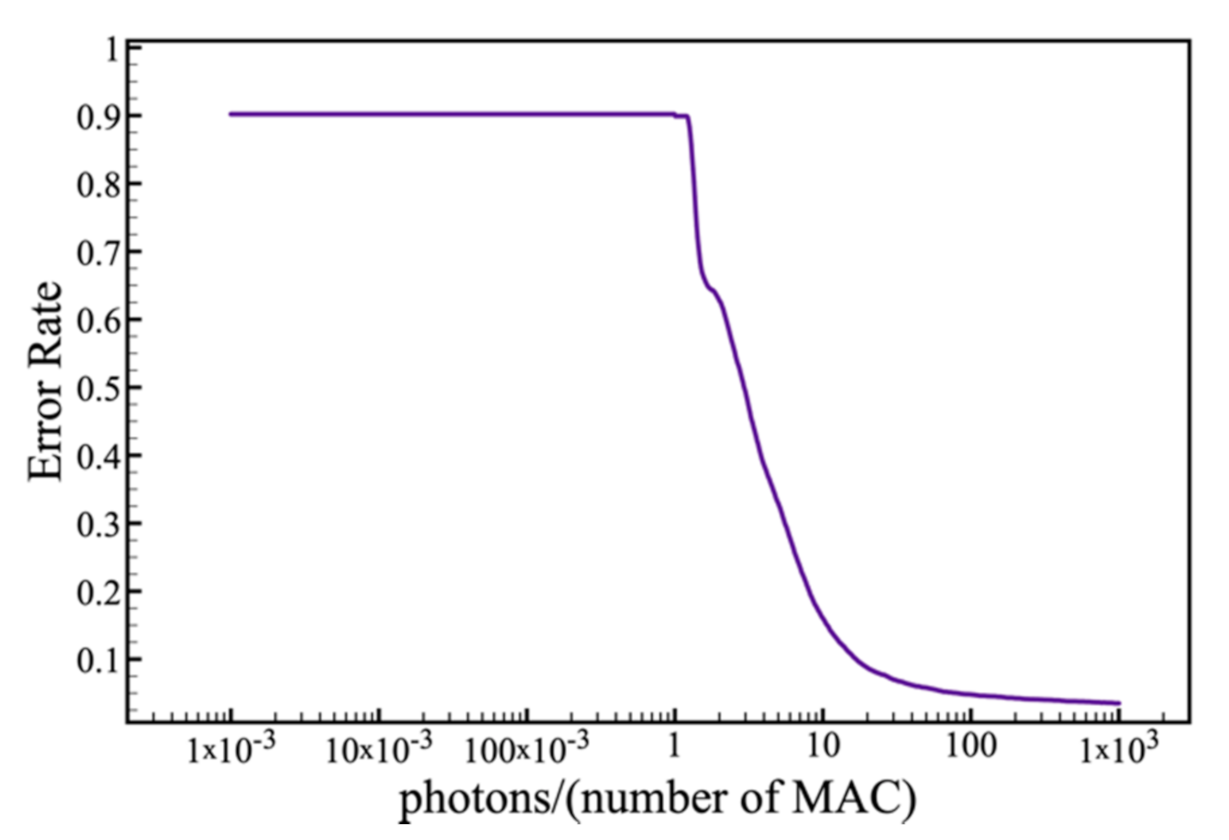
In the previous work, we simulated a layer and multi-layer model with granular noise [15]. To get closer to reality, the noise effect expressed by Equation (3) was added to the simulation process exactly following the procedure mentioned in Section 2.1. The result in Figure 4 shows that when the p h o t o n / n M A C is large enough, the error rate is not affected.

2.3. Quantization

As we mention in Section 3.2, quantization is needed to ensure higher accuracy when converting analog and digital circuits. Integer quantization is an optimization strategy that converts a 32-bit floating-point number (FP32), such as weights and activation outputs, to the nearest 8-bit fixed-point number (INT8). This leads to smaller models and faster reasoning, which is valuable for low-power devices such as microcontrollers [18].
Two main methods are used in the quantification process: (1) post-training integer quantification—using FP32 weight and input to train the model, and then quantifying the weight [20]. The main advantage of this is that it is easy to use. The drawback is the decrease in accuracy. (2) Quantization-aware training—weights are quantified in the training process, and calculated for quantization [21]. This is the best result when using INT8 quantization, but is much more complex than other methods.
A large amount of work has shown that a more efficient deep neural network (DNN) can be achieved through low bit quantization [22,23]. Experimental results using low precision numerical representations indicate that these experiments require higher precision than eight bits to deal with backward propagation and gradient [2,24,25]. This will make the implementation of the training more complicated. Therefore, after training the model, it is reasonable to only use the quantized weight for reasoning [21].
The quantization equation from FP to INT is shown as Equation (4):
Q = R S + Z
The inverse quantization equation from INT to FP is shown as Equation (5):
R = Q Z × S
where R represents the real FP value, Q represents the quantized INT value, Z represents the quantized INT value corresponding to the FP value, and S is the minimum scale that can be represented after the quantization of INT. The evaluation equations of S and Z are shown in Equations (6) and (7), respectively:
S = R m a x R m i n Q m a x Q m i n
where R m a x represents the maximum FP value, R m i n represents the minimum, Q m a x represents the maximum INT value, and Q m i n represents the minimum.
Z = Q m a x R m a x ÷ S
where each symbol represents the meaning as in the description above.
Here, S and Z are quantized parameters, while Q and R can be evaluated by the equation. Truncation would be needed where the quantized Q or the FP value R obtained by backward derivation are beyond their maximum range.

3. Simulation and Results

In normal electrical neural networks, float numbers are generally used in the model. In the analog neural network, due to the AD/DA conversion, we needed to quantify the FP32 into INT8 in the model. Quantification is common in deep learning and is faster because there are fewer bits, making models lighter. In order to verify the influence of quantization on optical neural networks, we conducted two steps. First, we quantify the model as INT8 after training. Then, we added a noise model for inference. Python language, TensorFlow framework, and MNIST data set were used for simulation.

3.1. Evaluation Criteria

Different classification algorithms use different variants. We need to select the algorithm according to the specific task. A suitable algorithm must be selected out according to the specific task. Accuracy is the most common evaluation index in the classification algorithm, as shown in Equation (8):
a c c u r a c y = T P + T N P + N
where TP is the number of cases that are correctly detected positive, and TN is the number of cases correctly classified as negative. P and N are positive and negative cases, respectively. ‘TP + TN’ presents all numbers that have been recognized correctly. ‘P+N’ presents all numbers obtained in MNIST. Accuracy means the proportion of the samples that are correctly predicted in all samples. Generally speaking, the higher the accuracy, the better the classifier.

3.2. Model Establishment

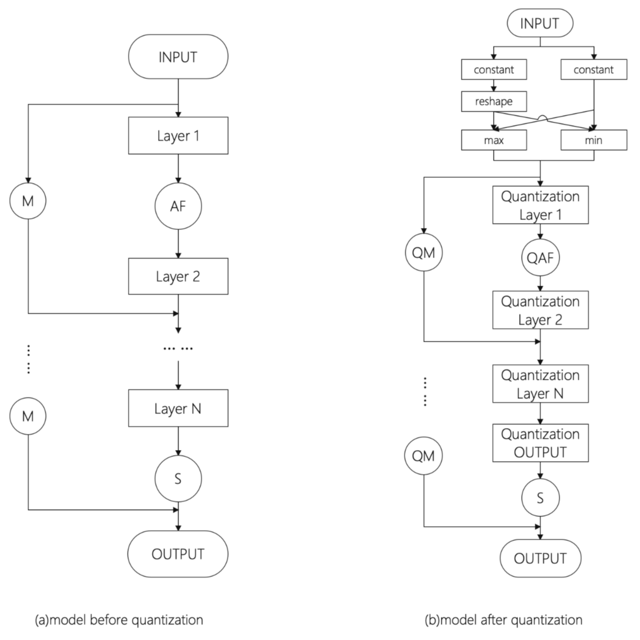
The model is established to classify and identify MNIST by the common fully connected network and evaluated with 3.1 evaluation standard, and the accuracy rate was 98%. Up to 98% accuracy rate was obtained through the evaluation standard. Then, the model is frozen to obtain a protocol buffer (PB) model file. Data can be viewed from each node in Neuron, as shown in Figure 5, where each node is FP. FP32 is converted to INT8 using TensorFlow Graph, and the result can also be viewed in Neuron.
The models we established are shown in Figure 5. In Figure 5, M represents Matmal and QM represents quantization of the results of Matmal. AF represents activation function, and QAF represents quantization activation function. S represents Softmax, which is a classification function.

3.3. Model Training

We conducted a quantitative inference test on the FCNN mentioned in Section 2.1 and the evaluation method used in Section 3.1. The results are shown in Table 1 and Figure 6.
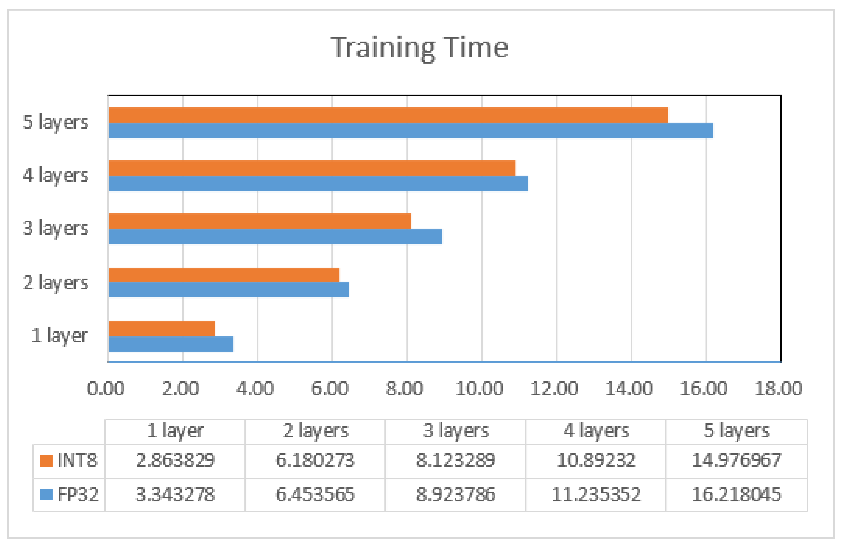
In Table 1, the results show that the optimized quantitative model is effective, and a high prediction accuracy was obtained when the INT8 model parameter size was 1/4 of the FP32. The neural network is too parameterized to contain enough redundant information, and cutting out such information will not result in a significant reduction in accuracy. For a given quantization method, there is no significant accuracy gap between the over-parameterized large FP32 and INT8 network; Figure 6 shows the reduction in training time when the INT model is used instead of FP. Since the inference of the network takes time, the reduction in training time is not proportional to the reduction in model size.

3.4. Noise

The basic components of the FCNN layer are MAC operations, which can be easily parallelized. The model structure is shown in Figure 7. Figure 7a shows the model with noise before quantization. The model we designed is based on Equation (3). Figure 7b shows the model with noise after quantization. All the parameters are quantized. In order to achieve high-performance, highly parallel computing paradigms, the method we used is post-training integer quantification.
In Figure 7, M, QM, and S are the same means as Figure 6. Q+ represents quantization plus.
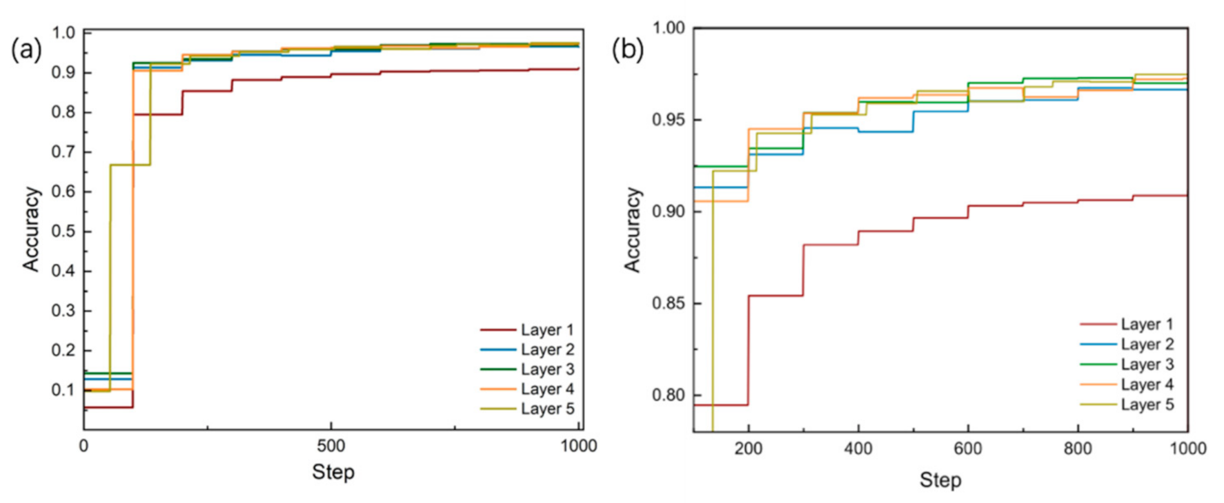
We found that when the MAC reached a certain size, the noise had little impact on accuracy. The result is shown in Figure 8.
We quantified the noise model and carried out the inference test. The results are shown in Table 2.
The results in the table show that our model has high accuracy and stability. When the model was shrunk by 1/4, the evaluation index was reduced by only 0.3–1%. According to the results, it can be observed that there is no significant increase in accuracy when the number of layers is increased to more than two layers. This is caused by the excessive redundant information due to the insufficient amount of data.
Compared with the model in Section 3.3, the neural network with noise has more parameters. Therefore, the search space of the model will be larger, so the spatial distribution of the model can be better described only if there are enough data. As a result, the model with noise has higher accuracy.

4. Conclusions

In this paper, we propose a quantitative method for adapting ONN to a non-ideal environment with INT transmission based on a fully connected neural network image classification and recognition model proposed in previous work [15]. Through the comparison before and after quantization, the optimized quantization model in this paper is effective and has good enough prediction accuracy. Accuracy can be achieved up to about 96%. The experimental results show that, compared with the electrical method, the proposed quantization method can effectively solve the non-ideal ONN problem. We believe that the quantization model established in this paper can be of great help to optical chips in the near future. However, it is still difficult to implement large-scale photonic neural networks based on current technology. Besides, ONNs have a limited number of neurons. In future research, we will extend the model and address photon limitations. Larger datasets for training experiments such as ImageNet will also be used.

Author Contributions

D.Z., Y.Z. (Yejin Zhang) and Y.Z. (Ye Zhang) designed and built model, processed data and writed article. Y.S., J.P. and J.Y. and embellished the article. R.W., P.W., X.Z. and G.L. provides ideas and technology. All authors have read and agreed to the published version of the manuscript.

Funding

This work is supported by the Beijing Natural Science Foundation (Z200006), the National Natural Science Foundation of China (62090053, 61934007, 61974141), the Beijing Municipal Science and Technology Project (Z191100004819011), the National Key R&D Program of China (2018YFE0203103), and the Supplementary and Supportive Project for Teachers at the Beijing Information Science and Technology University (5029011103).

Institutional Review Board Statement

Not applicable.

Informed Consent Statement

Not applicable.

Data Availability Statement

All data and models generated during the study appear in the submitted article.

Conflicts of Interest

The authors declare no conflict of interest.

References

  1. Gallus, J. Fostering Public Good Contributions with Symbolic Awards: A Large-Scale Natural Field Experiment at Wikipedia. Manag. Sci. 2017, 63, 3999–4015. [Google Scholar] [CrossRef] [Green Version]
  2. Tkachenko, R.; Izonin, I.; Vitynskyi, P.; Lotoshynska, N.; Pavlyuk, O. Development of the Non-Iterative Supervised Learning Predictor Based on the Ito Decomposition and SGTM Neural-Like Structure for Managing Medical Insurance Costs. Data 2018, 3, 46. [Google Scholar] [CrossRef] [Green Version]
  3. Shen, Y.; Harris, N.C.; Skirlo, S.; Prabhu, M.; Baehr-Jones, T.; Hochberg, M.; Sun, X.; Zhao, S.; LaRochelle, H.; Englund, D.; et al. Deep learning with coherent nanophotonic circuits. Nat. Photon. 2017, 11, 441–446. [Google Scholar] [CrossRef]
  4. Hamerly, R.; Bernstein, L.; Sludds, A.; Soljačić, M.; Englund, D. Large-Scale Optical Neural Networks Based on Photoelectric Multiplication. Phys. Rev. X 2019, 9, 021032. [Google Scholar] [CrossRef] [Green Version]
  5. Zhang, H.; Gu, M.; Jiang, X.D.; Thompson, J.; Cai, H.; Paesani, S.; Santagati, R.; Laing, A.; Zhang, Y.; Yung, M.H.; et al. An optical neural chip for implementing complex-valued neural network. Nat. Commun. 2021, 12, 1–11. [Google Scholar]
  6. Anika, N.J.; Mia, B. Design and analysis of guided modes in photonic waveguides using optical neural network. Optik 2021, 228, 165785. [Google Scholar] [CrossRef]
  7. Hughes, T.W.; Minkov, M.; Shi, Y.; Fan, S. Training of photonic neural networks through in situ backpropagation and gradient measurement. Optica 2018, 5, 864–871. [Google Scholar] [CrossRef]
  8. Williamson, I.A.D.; Hughes, T.W.; Minkov, M.; Bartlett, B.; Pai, S.; Fan, S. Reprogrammable Electro-Optic Nonlinear Activation Functions for Optical Neural Networks. IEEE J. Sel. Top. Quantum Electron. 2020, 26, 1–12. [Google Scholar] [CrossRef] [Green Version]
  9. Pai, S.; Bartlett, B.; Solgaard, O.; Miller, D.A.B. Matrix Optimization on Universal Unitary Photonic Devices. Phys. Rev. Appl. 2019, 11, 064044. [Google Scholar] [CrossRef] [Green Version]
  10. Gu, J.; Zhao, Z.; Feng, C.; Zhu, H.; Chen, R.T.; Pan, D.Z. ROQ: A noise-aware quantization scheme towards robust optical neural networks with low-bit controls. In Proceedings of the Design, Automation & Test in Europe Conference & Exhibition (DATE), Grenoble, France, 9–13 March 2020; IEEE: Piscataway, NJ, USA, 2020. [Google Scholar]
  11. Harris, N.C.; Ma, Y.; Mower, J.; Baehr-Jones, T.; Englund, D.; Hochberg, M.; Galland, C. Efficient, compact and low loss thermo-optic phase shifter in silicon. Opt. Express 2014, 22, 10487–10493. [Google Scholar] [CrossRef] [PubMed] [Green Version]
  12. Fang, M.Y.-S.; Manipatruni, S.; Wierzynski, C.; Khosrowshahi, A.; Deweese, M.R. Design of optical neural networks with component imprecisions. Opt. Express 2019, 27, 14009–14029. [Google Scholar] [CrossRef] [PubMed] [Green Version]
  13. Tait, A.N.; Nahmias, M.A.; Shastri, B.J.; Prucnal, P.R. Broadcast and Weight: An Integrated Network for Scalable Photonic Spike Processing. J. Light. Technol. 2014, 32, 4029–4041. [Google Scholar] [CrossRef]
  14. Slussarenko, S.; Weston, M.M.; Chrzanowski, H.M.; Shalm, L.K.; Verma, V.B.; Nam, S.W.; Pryde, G.J. Unconditional violation of the shot-noise limit in photonic quantum metrology. Nat. Photon. 2017, 11, 700–703. [Google Scholar] [CrossRef] [Green Version]
  15. Zhang, D.; Wang, P.; Luo, G.; Bi, Y.; Zhang, Y.; Yi, J.; Su, Y.; Zhang, Y.; Pan, J. Design of a Silicon-based Optical Neural Network. In Proceedings of the 2nd International Conference on Mathematics, Modeling and Simulation Technologies and Applications (MMSTA 2019), Xiamen, China, 27–28 October 2019; Atlantis Press: Dordrecht, The Netherlands, 2019. [Google Scholar]
  16. Hsu, K.-Y.; Li, H.-Y.; Psaltis, D. Holographic implementation of a fully connected neural network. Proc. IEEE 1990, 78, 1637–1645. [Google Scholar] [CrossRef]
  17. The Dataset MNIST. Available online: http://yann.lecun.com/exdb/mnist/ (accessed on 12 April 2021).
  18. Hinton, G.; Oriol, V.; Dean, J. Distilling the knowledge in a neural network. arXiv 2015, arXiv:1503.02531. [Google Scholar]
  19. Song, Q.; Zhao, Z.; Liu, Y. Stability analysis of complex-valued neural networks with probabilistic time-varying delays. Neurocomputing 2015, 159, 96–104. [Google Scholar] [CrossRef]
  20. Jacob, B.; Kligys, S.; Chen, B.; Zhu, M.; Tang, M.; Howard, A.; Adam, H.; Kalenichenko, D. Quantization and training of neural networks for efficient integer-arithmetic-only inference. In Proceedings of the IEEE Conference on Computer Vision and Pattern Recognition, Salt Lake City, UT, USA, 18–23 June 2018. [Google Scholar]
  21. Zhou, S.; Wu, Y.; Ni, Z.; Zhou, X.; Wen, H.; Zou, Y. Dorefa-net: Training low bitwidth convolutional neural networks with low bitwidth gradients. arXiv 2016, arXiv:1606.06160. [Google Scholar]
  22. Moren, K.; Goehringer, D. A framework for accelerating local feature extraction with OpenCL on multi-core CPUs and co-processors. J. Real-Time Image Process. 2019, 16, 901–918. [Google Scholar] [CrossRef]
  23. Wu, J.; Leng, C.; Wang, Y.; Hu, Q.; Cheng, J. Quantized Convolutional Neural Networks for Mobile Devices. In Proceedings of the IEEE Conference on Computer Vision and Pattern Recognition (CVPR), Las Vegas, NV, USA, 27–30 June 2016; IEEE: Piscataway, NJ, USA, 2016. [Google Scholar]
  24. Dettmers, T. 8-bit approximations for parallelism in deep learning. arXiv 2015, arXiv:1511.04561. [Google Scholar]
  25. Gupta, S.; Agrawal, A.; Gopalakrishnan, K.; Narayanan, P. Deep learning with limited numerical precision. In Proceedings of the International Conference on Machine Learning, Lille, France, 6–11 July 2015. [Google Scholar]
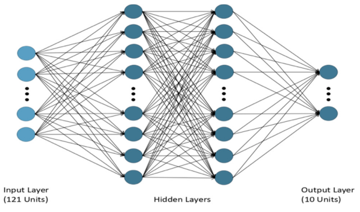
Figure 1. FCNN structure.
Applsci 11 03692 g001
Figure 2. Chip design (a) of an ONN chip structure. (b) Matrix multiplication concept diagram. The chip is implemented for each layer of the network structure. Matrix multiplication is performed by combining the input target signal (yellow) and the weight signal (blue) and translating them to the balance detector for detection.
Applsci 11 03692 g002
Figure 3. Schematic diagram of the optoelectronic system.
Applsci 11 03692 g003
Figure 4. Error rate vs. p h o t o n / n M A C .
Applsci 11 03692 g004
Figure 5. Compare models (a) before and (b) after quantization.
Applsci 11 03692 g005
Figure 6. Training time of models before quantization.
Applsci 11 03692 g006
Figure 7. Model with noise (a) before and (b) after quantization.
Applsci 11 03692 g007
Figure 8. Train accuracy with noise (a) Accuracy from step 1. (b) Accuracy form step 100.
Applsci 11 03692 g008
Table 1. Accuracy comparison between FP32 and INT8 in different layers.
Number of LayersFP32INT8Total
Consumption
Layer 10.79030.7791 3.32 × 10 7
Layer 20.93710.9366 4.96 × 10 7
Layer 30.94170.9386 6.59 × 10 7
Layer 40.95510.9501 8.23 × 10 7
Layer 50.96350.9602 9.87 × 10 7
Table 2. Accuracy comparison between FP32 and INT8 in different layers with noise.
Number of LayersFP32INT8
Layer 10.91170.9038
Layer 20.96630.9627
Layer 30.96780.9675
Layer 40.97270.9721
Layer 50.97490.9743
Publisher’s Note: MDPI stays neutral with regard to jurisdictional claims in published maps and institutional affiliations.