1. Introduction
Optical probes [
1,
2] are widely used in optical coherence tomography (OCT) and other sensing and imaging systems for investigating the internal structures of biological tissues and the intraluminal imaging of various organs. However, conventional probes are bulky and unwieldy, and thus, researchers have considered replacing them with lensed optical fibers [
3,
4,
5]. In particular, a set of two lensed optical fibers can replace existing bulky optical lens systems for constructing compact microelectromechanical systems (MEMS) that can afford significantly improved imaging performances [
6].
There are several conventional methods for fabricating the lensed optical fibers used in such compact MEMS setups. Current methods for introducing surface curvature at the optical-fiber tip include curing a photoreactive polymer with ultraviolet light [
7], polishing the end tip of the fiber [
8], melting the optical-fiber tail via arc discharge [
6,
9], and fusing a GRIN lens with the optical fiber [
10].
Two of the abovementioned methods have found wide usage in the fabrication of lensed optical fibers. The first method involves fusing a GRIN lens with a gradually varying refractive index into an optical fiber, which requires very precise cleaving. In this method, a section of the GRIN lens is precisely cut off to focus a beam at the right position; however, the method requires precise calculations of the optical beam path within the GRIN lens. The second method involves attaching a coreless silica fiber (CSF) to an optical fiber and using an arc discharge to shape the radius of curvature at the end of the CSF to form a lens [
9]. With this approach, a beam from a lensed optical fiber can be made to converge or diverge depending on the CSF length and the radius of curvature of the CSF tip. This method also requires the precise cleaving of optical fibers to precisely adjust the CSF length. In addition to precise cleaving, it is also necessary to make the CSF end suitably curved. Thus, it is difficult to fabricate a lensed fiber using a CSF when compared with GRIN-lens-based fabrication. However, a specific focal length of the GRIN lens for a lensed optical fiber cannot be easily obtained for customized needs. Furthermore, precise cleaving is also necessary for using a GRIN lens when compared with the CSF-based method.
Against this backdrop, in this work, we apply a new method to fabricate lensed optical fibers with desired focal lengths by using femtosecond and CO
2 lasers. Here, the femtosecond laser is used to precisely cleave a CSF [
11,
12,
13] directly without being heavily affected by thermal effects. We note that our precise CSF cleaving technique using a femtosecond laser has been implemented previously, demonstrating its superiority over conventional micromachining, which cannot be used to precisely fabricate an optical fiber [
12]. Furthermore, the proposing method is simpler than the conventional method involving polishing processes together with thermal processing [
14,
15].
The CO
2 laser with a wavelength of 10.6 μm and having a suitable absorption rate for silicon material is used to melt the CSF tip to form the lens curvature. The method also yields a more uniform and consistent radius of curvature with a precision of ≤1 μm at the end of the optical fiber along with the desired focal length when compared with the widely used conventional arc discharge method [
6,
9]. The combination of cleaving a fiber and forming a lens on the optical-fiber tip described above provides a versatile approach to fabricate lensed optical fibers with precise focal lengths.
In our study, the focal length and size of the beam emerging from the manufactured lensed optical fibers are measured using a knife-edge method [
16] and compared with the counterpart theoretical values. For calculation, we use the ABCD method for a Gaussian beam [
17] to analyze beam propagation at the CSF section after beam divergence from the lead single-mode fiber (SMF) and focusing by the lensed fiber.
2. Ray Tracing Using Gaussian ABCD Matrix
Figure 1 shows the propagation of a beam through a lensed optical fiber composed of an SMF and a CSF section. The beam propagating through the SMF with a core diameter of 9 μm can be approximated as a Gaussian paraxial beam, and therefore, we can apply the ABCD matrix law with complex parameter q(z) to define the beam waist (ω) and the radius of wavefront curvature (R) [
18] of the beam as a function of the axial distance z. Consequently, we can determine a focal length L
f, the distance from the end of the lens to the plane where the beam has a minimum beam waist (ω
2), as shown in
Figure 1.
The evolution of the q-parameter can be calculated with the ABCD matrix, whose elements are given in matrix M. Parameter q
1 of the beam at the end of the SMF is related to the parameter q
2 at the focal plane as:
where matrices M
01, M
12, M
23, and M
34 track the ray paths as per the paraxial optical approximation. Here, each of the matrices was calculated as [
19,
20]
Here, M01 denotes the ray matrix of the beam diverging from the boundary between the SMF and CSF, with n0 = n1. Moreover, M12 describes the propagation of the beam through the CSF along geometrical path LC instead of optical path nLC, which is the length LC between the exits of the SMF and the CSF in the case of the paraxial approximation. In addition, M23 describes the path of the ray refracted by the lens and M34 the ray path from the curvature of the lensed optical fiber with focal length Lf, with n1 being the refractive index of the optical fiber of the CSF and n2 the refractive index of air.
At the focal plane, because the Gaussian beam has an infinite radius of curvature there, we can calculate L
f and ω
2 as a function of R and L
C:
where
Figure 2 shows the behavior of L
f calculated as functions of R and L
C; the figure was generated using MATLAB. Here, λ denotes the operating wavelength of 1550 nm and ω
1 = 5.2 μm, which is half the mode field diameter (MFD) of the SMF. We use the MFD because the actual Gaussian beam size can be obtained from the size of the beam emerging partially from of the cladding of the SMF, and this beam is ~1 μm larger than the actual core size [
21].
From
Figure 2, we can estimate that the R value must lie between ~70 μm and 120 μm and the L
C value must lie between ~275 μm and 400 μm to obtain the desired focal length of 375 μm (as indicated by the thick red contour line). The yellow region inside the red contour line in
Figure 2 shows the L
C and R regime required for converging focal lengths instead of diverging negative focal lengths.
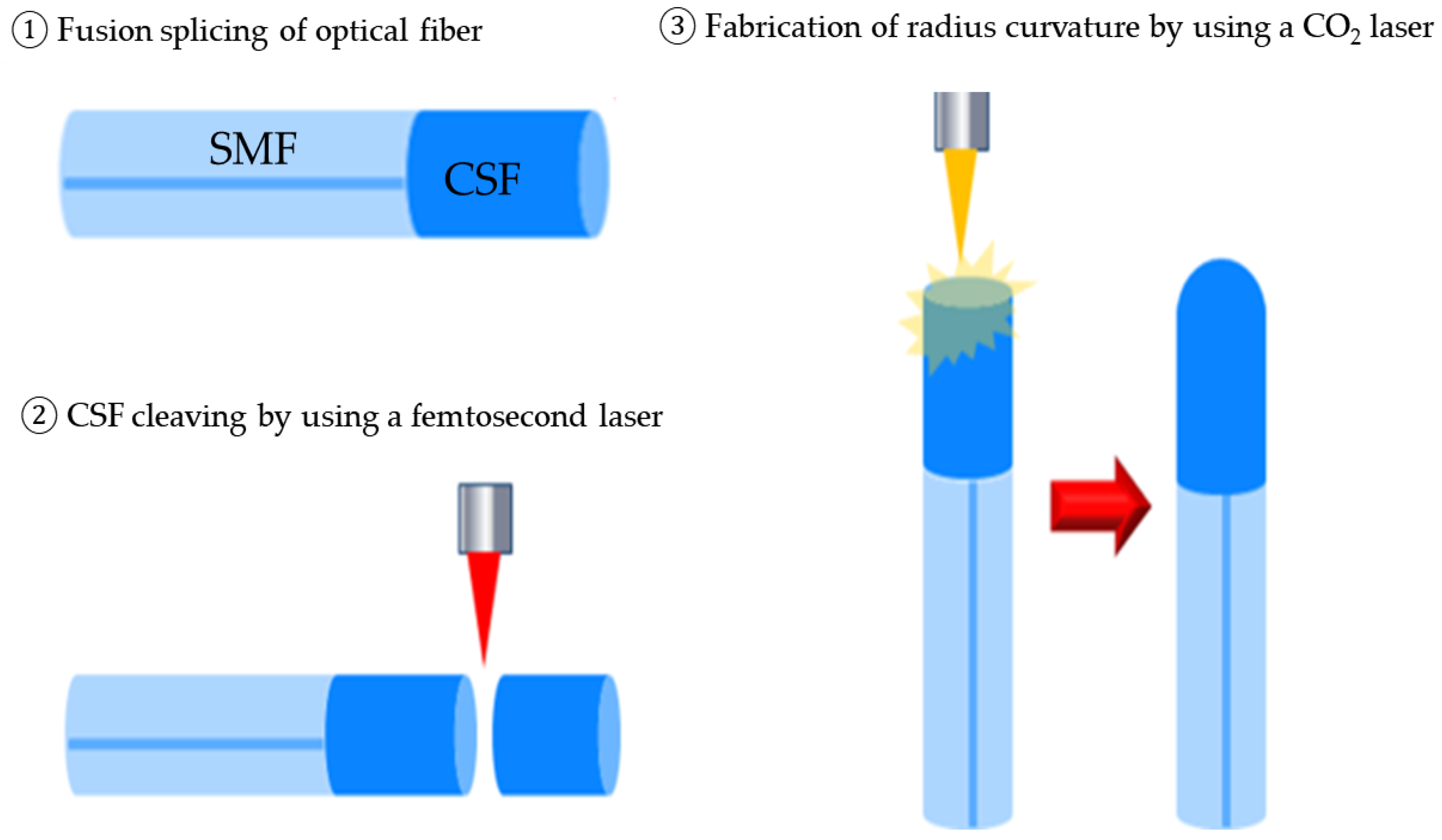
3. Experimental Methods
Figure 3 shows the procedure to fabricate an optical fiber integrated with a lens: (1) the SMF and CSF are fused by using an optical fiber fusion splicer, followed by (2) CSF cleaving using a femtosecond laser. Subsequently, the lens curvature is formed by (3) melting the clipped CSF tip using a CO
2 laser.
3.1. CSF Cleavage Using a Femtosecond Laser
To cleave the CSF precisely, we used a light-conversion Yb:KGW diode-pumped femtosecond laser (Model: Pharos) with a pulse repetition rate of 10–200 kHz, center wavelength of 1030 nm, pulse width of 250 fs, and maximum output of 6 W. The micromachining system consisted of X-and Y-axis linear motors with a moving range of 300 mm × 300 mm and a maximum feeding rate of 300 mm/s. The resolution of the X- and Y-axes of the stage was 20 nm/count; we note here that the accuracy of the optical-fiber cleaving length of the CSF when using a femtosecond laser is governed by the resolution of the moving stage.
CSF cleavage was performed with the use of a jig with two holders to grip the CSF. One of the holders was moveable, and tension was applied along one direction. The femtosecond laser was operated at a repetition rate of 10 kHz and an output power of 23 mW. The processing speed was 0.1 mm/s, and line processing was performed once. The cleavage measurement of the CSF cut to a design length of 300 μm resulted in an actual length of 300.4 μm, corresponding to a cutting precision of ≤1 μm.
3.2. Formation of the Radius of Curvature Using a CO2 Laser
To shape the tip of the CSF into a curved surface, we varied the beam-exposure time and laser power of a coherent CO2 laser (Model name: Diamond C-55L) having a central wavelength of 10.6 μm and a maximum output of 55 W. The beam was defocused a little to make the beam size larger than the tip size of the CSF using an object lens with the focal length of 25 mm. The machining range along the X and Y axes of the CO2 laser processing system was 300 mm × 300 mm, with an accuracy of 1 μm. The maximum movement range of the Z-axis stage was 150 mm, with an accuracy of 1 μm. To form the curvature of the CSF tip, the optical fiber was placed parallel to the direction of the CO2 laser beam using a CCD and moved with the use of XY and Z stages such that the fiber was located a little away from the focal plane of the CO2 laser beam. A jig was used to fix and adjust the inclination of the optical fiber.
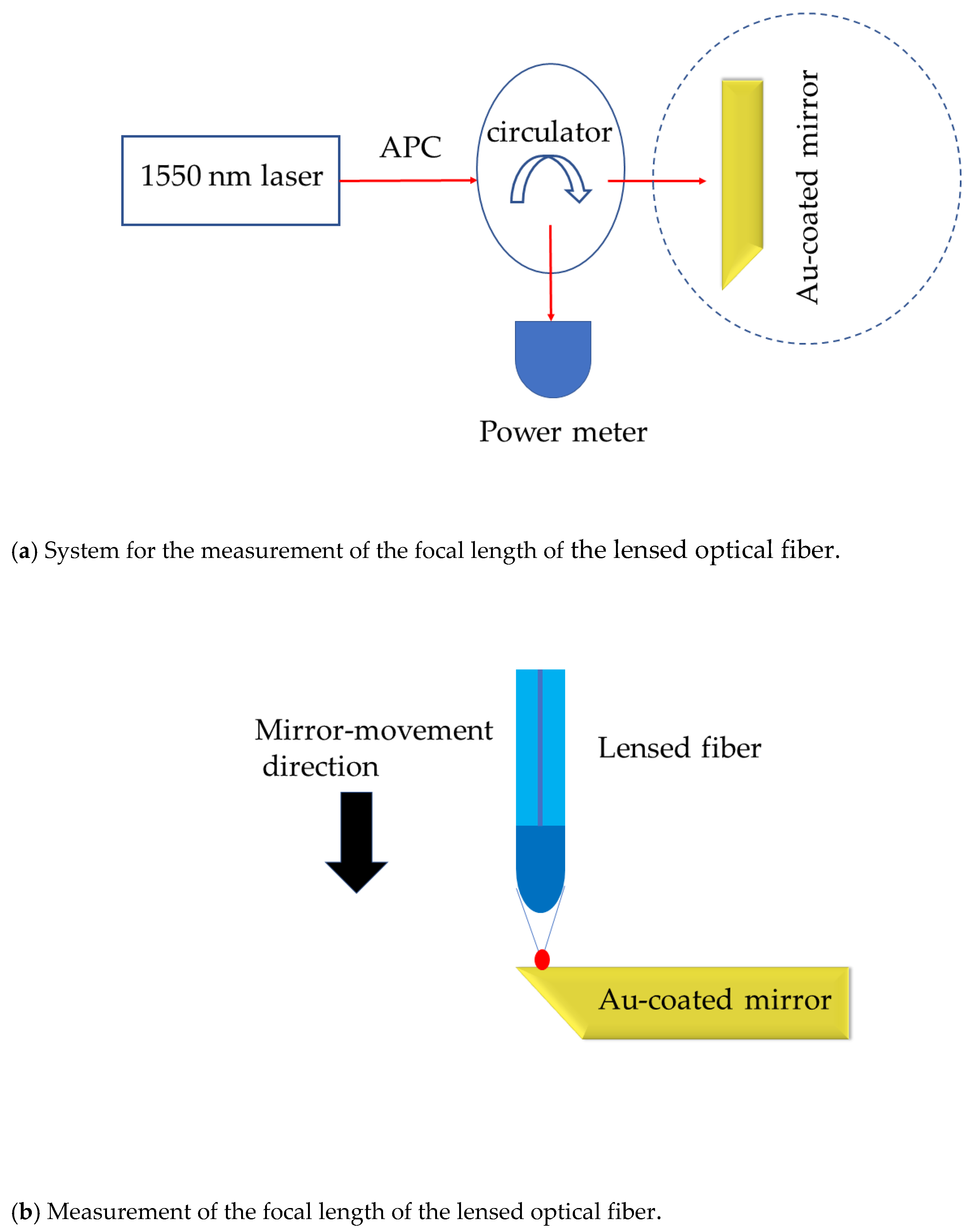
3.3. Measurement of Focal Length and Beam Size
Figure 4 shows the scheme used to measure the focal length and size of the beam emitting from the fabricated lensed optical fiber. Here, we used a laser light source with the operating wavelength of the SMF, i.e., 1550 nm. Because the tip of the circulator shown in
Figure 4 was the APC-type, an APC-type ferrule was connected to the lensed optical fiber. In this setup, the laser beam with a wavelength of 1550 nm passes through the circulator, is made incident on the lensed optical fiber, and is reflected from the Au-coated mirror with good reflectance across all wavelength bands. The reflected beam again converges at the lensed optical fiber, and the beam travels to the laser power meter through the circulating device. In the study, the gold-coated mirror was moved in steps of 1 μm, and the change in the output power with respect to the mirror distance was measured using a laser-power measuring device. The mirror position at which the strongest output power was obtained as per the power meter was determined as the focal point of the lensed optical fiber.
The mirror was also moved laterally by 1 μm, and the output of the beam was measured.
Figure 4c shows the method for measuring the Gaussian-beam profile using the knife-edge method. The method measures only a part of the laser power, except that of the Gaussian beam blocked by the knife edge, as a function of lateral mirror-position variation [
18]. Thus, the Gaussian beam profile can be obtained from the laser-power gradient. The 1/e
2 points of the obtained line profile can be obtained using these beam profiles, and consequently, the beam size can be determined.
4. Experimental Results and Discussions
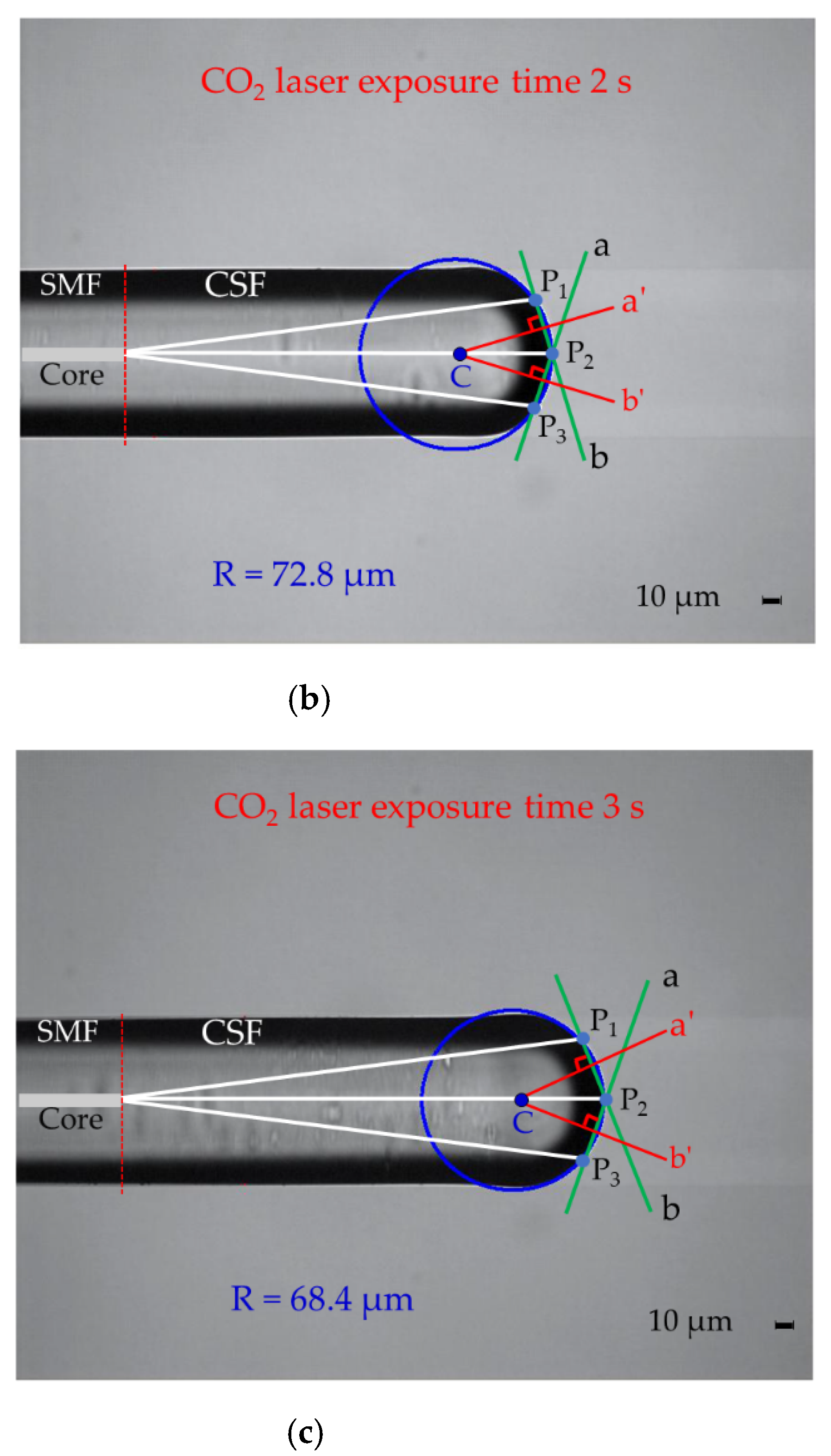
4.1. Measurement of the Radius of the Curvature of the Lensed Optical Fiber
Figure 5 shows the microscopic images of the lens fabricated using the CO
2 laser as a function of the exposure time. Spherical shapes are formed at the ends of the optical fibers instead of ellipsoidal shapes owing to internal material cohesion resulting from the melting of the optical fiber tips in the region where the lens curvature is shaped as a function of the CO
2 laser exposure time. The circular cross-section of the sphere was confirmed by comparing the formed circular perimeter with the perimeter drawn using the calculated radius of curvature.
Figure 6 illustrates the method for measuring the radius of curvature of the fabricated lensed optical fiber. Three different points (P
1, P
2, and P
3) on the formed circular perimeter, including the vertex (P
2) of the formed sphere, are chosen as shown. Two different line segments (P
2P
1 and P
2P
3) are drawn from the vertex (P
2) of the sphere. Additionally, two bisectors, a′ and b′, are drawn perpendicular to line segments a and b, respectively, which meet at the center of the circle, coinciding with the central coordinates of the sphere.
4.2. Measurement of the Focal Length and Beam Size
The mirror reflection method and the knife-edge method [
14] were used to measure the focal length of the fabricated lensed optical fiber and the beam size at the focal plane, respectively.
The dimensions of the lensed fiber used for these measurements were L
C = 308 μm and R = 72.8 μm in
Figure 5b. Here, we note that the L
C value immediately after cleaving with the femtosecond laser was measured to be 300.4 μm. However, after lens formation with the CO
2 laser, the L
C value increased to 308 μm, with a length increase of ~7 to 8 μm.
Figure 7a shows the measurement results of the focal length of the fabricated lensed optical fiber. The intensity of the beam reflected by the mirror and returned to the lensed optical fiber was measured in terms of the mirror distance from the fiber tip. From the figure, we note that the largest intensity corresponds to a mirror distance of 375 μm, that is, the focal length of the lensed optical fiber.
Figure 7b shows the measurement of the beam size. By moving a sharp knife edge transversely in steps of 1 μm across the focal plane, we measured the intensity of the beam reflected by the knife edge in terms of the edge position. The figure shows the measured data (dotted black line), their fitting with a Boltzmann curve, and the differentiated curve denoted by the solid blue line. The knife edge was moved to reflect light from the mirror whenever the mirror position was changed by 1 μm. From the measurement of the 1/e
2 value of the intensity profile (blue line), we measured the beam size as 27 μm.
4.3. Calculation of Focal Length and Beam Size
The measured focal length of the sample fiber with L
C = 308 μm and R = 72.8 μm was 375 μm; on the other hand, the theoretical focal length was 406 μm, corresponding to a difference of 31 μm. This difference between the measured and calculated focal lengths may be due to the uncertainty in the MFD of the SMF. The MFD of the SMF-28 communication optical fiber (Corning Corp.) used in this study was 10.4 ± 0.5 μm.
Figure 8 shows the graph obtained by substituting the values of the nearby MFDs within the error range. We note that as the MFD value decreases by 0.1 μm, the focal length is sensitively changed by 10 μm. The red dotted line in
Figure 8 indicates the focal length obtained by substituting the average MFD value of 5.2 μm to obtain the theoretical focal length. We note here that the error further depends on the optical-alignment conditions.
The beam size for the focal length of 406 μm was also measured using the knife-edge method, and it was estimated as 27 μm at 1/e2 of the peak intensity. When compared with the theoretical beam size of 23 μm at the 2ωz point, the error was 4 μm.
5. Conclusions
We propose and demonstrate a new method for fabricating precisely a lensed fiber with a desired focal length by cleaving a CSF using an ultrafast femtosecond laser without appreciable thermal effects and forming the radius of curvature at the end of this optical fiber using a CO
2 laser. In our study, a precisely cleaved segment of a CSF was obtained using a femtosecond laser and the segment was attached to a long SMF. The CO
2 laser was used to melt the end of the coreless fiber to precisely shape the radius of curvature with a precision of ≤1 μm as a function of the exposure time and the power of the CO
2 laser beam, thereby resulting in a focal length as close as possible to the design value using simulated parameters in
Figure 2. This technique forms an alternative to other conventional methods for forming fiber lenses for biosensing applications. The method can be used to realize a broad range of focal lengths with variable CSF lengths and curvature radii of the lenses for application to various imaging requirements.
In the study, we used a CO2 laser to fabricate a lensed optical fiber with LC = 308 μm and R = 72.8 μm at the end of the CSF. The simulated and calculated focal lengths were compared with the actually measured focal length. Furthermore, the MFD of the SMF-28 communication optical fiber was varied from 9.9 μm to 10.9 μm, and the obtained focal length of 406 μm with the mean MFD differed from the designed and theoretical focal distance of 375 μm. This difference between the measured and the calculated focal lengths can be attributed to the uncertainty associated with the MFD.
The beam size at the focal length of 406 μm was also measured using the knife-edge method, and it was estimated as 27 μm at 1/e2 of the peak intensity. The theoretical beam size was 23 μm at the 2ωz point, corresponding to an error of 4 μm with respect to the experimental value. These findings indicate that it is possible to fabricate a lensed optical fiber with a desired focal length by using femtosecond and CO2 lasers. Furthermore, lenses with optimum converging and diverging focal lengths can be obtained by varying LC and R for diverging or converging the light. Therefore, these lenses can be used as fine optical elements in OCT or MEMS.
In the study, we applied the paraxial approximation based on the ABCD matrix to trace the focal point; however, in future, it would be worthwhile to confirm the difference between the measured and the calculated focal lengths with general approaches using ray-tracing methods. We also plan to examine the systematic statistical repeatability and precision of fabricated micro-lenses using a large number of fabricated samples to determine the shortest range of focal lengths possible with the method.
Author Contributions
Conceptualization, K.-D.L., I.-B.S. and J.-T.K.; methodology, K.-D.L., H.-K.C., I.-B.S. and J.-T.K.; software, K.-D.L. and J.-T.K.; validation, I.-B.S., B.-H.L. and J.-T.K.; formal analysis, K.-D.L. and J.-T.K.; investigation, K.-D.L. and J.-T.K.; writing—original draft preparation, J.-T.K.; writing—review and editing, B.-H.L. and J.-T.K.; visualization, J.-T.K.; supervision, I.-B.S. and J.-T.K.; project administration, I.-B.S. and J.-T.K. All authors have read and agreed to the published version of the manuscript.
Funding
This research received no external funding.
Institutional Review Board Statement
Not applicable.
Informed Consent Statement
Not applicable.
Data Availability Statement
Not applicable.
Acknowledgments
The authors are grateful to Soongho Park (National Institutes of Health, USA) for providing valuable comments toward improving the original manuscript. This work was supported by a research fund from Chosun University (2019).
Conflicts of Interest
The authors declare no conflict of interest.
References
- Fujimoto, J.G.; Pitris, C.; Boppart, S.A.; Brezinski, M.E. Optical coherence tomography: An emerging technology for biomedical imaging and optical biopsy. Nat. Neoplasia 2000, 2, 9–25. [Google Scholar] [CrossRef] [PubMed] [Green Version]
- Huang, D.; Swanson, E.A.; Lin, C.P.; Schuman, J.S.; Stinson, W.G.; Chang, W.; Hee, M.R.; Flotte, T.; Gregory, K.; Puliafito, C.A.; et al. Optical coherence tomography. Science 1991, 254, 1178–1181. [Google Scholar] [CrossRef] [Green Version]
- Lee, B.H.; Min, E.J.; Kim, Y.H. Fiber-based optical coherence tomography for biomedical imaging sensing, and precision measurements. Opt. Fiber Technol. 2013, 19, 729–740. [Google Scholar] [CrossRef]
- Park, S.; Rim, S.; Kim, J.W.; Park, J.; Sohn, I.-B.; Lee, B.H. Analysis of design and fabrication parameters for lensed optical fibers as pertinent probes for sensing and imaging. Sensors 2018, 18, 4150. [Google Scholar] [CrossRef] [PubMed] [Green Version]
- Ryu, S.Y.; Choi, H.Y.; Na, J.H.; Choi, W.J.; Lee, B.H. Lensed fiber probes designed as an alternative to bulk probes in optical coherence tomography. Appl. Opt. 2008, 47, 1510–1516. [Google Scholar] [CrossRef] [PubMed]
- Wu, G.; Mirza, A.R.; Gamage, S.K.; Ukrainczyk, L.; Shashidhar, N.; Wruck, G.; Ruda, M. Design and use of compact lensed fibers for low cost packaging of optical MEMS components. J. Micromechanics Microengineering 2004, 14, 1367–1375. [Google Scholar] [CrossRef]
- Kim, K.-R.; Chang, S.; Oh, K. Refractive microlens on fiber using UV-curable fluorinated acrylate polymer by sur-face-tension. IEEE Photonics Technol. Lett. 2003, 15, 1100–1102. [Google Scholar]
- Tseng, Y.; Huang, J.; Su, W. Fabricating lensed fiber using a novel polishing method. J. Manuf. Sci. Eng. 2009, 131, 041016. [Google Scholar] [CrossRef]
- Qiu, Y.; Wang, Y.; Belfield, K.D.; Liu, X. Ultrathin lensed fiber-optic probe for optical coherence tomography. Biomed. Opt. Express 2016, 7, 2154–2162. [Google Scholar] [CrossRef] [Green Version]
- Wang, C.; Sun, J.; Sun, F.; Zhu, J.; Yuan, Z.; Asundi, A. Coupling efficiency of ultra-small gradient-index fiber probe. Opt. Commun. 2017, 389, 265–269. [Google Scholar] [CrossRef]
- Shah, L.; Tawney, J.; Richardson, M.; Richardson, K. Femtosecond laser deep hole drilling of silicate glasses in air. Appl. Surf. Sci. 2001, 183, 151–164. [Google Scholar] [CrossRef]
- Lim, K.D.; Choi, H.-K.; Kim, J.T.; Lee, J.K.; Sohn, I.-B. Precision cutting and cleaving of optical fiber with femtosecond and CO₂ Laser. J. Korean Soc. Precis. Eng. 2017, 34, 633–637. [Google Scholar] [CrossRef]
- Wang, Y.; Liao, C.R.; Wang, D.N. Femtosecond laser-assisted selective infiltration of microstructured optical fibers. Opt. Express 2010, 18, 18056–18060. [Google Scholar] [CrossRef] [PubMed] [Green Version]
- Boyd, K.; Rees, S.; Simakov, N.; Daniel, J.M.O.; Swain, R.; Mies, E.; Hemming, A.; Clarkson, W.A.; Haub, J. High precision 9.6 µm CO2 laser end-face processing of optical fibers. Opt. Express 2015, 23, 15065–15071. [Google Scholar] [CrossRef] [Green Version]
- Le’vesque, L.; Jdanov, V. Optical fiber cleaved at an angle by CO2 laser ablation: Application to micromachining. Opt. Laser Technol. 2010, 42, 1080–1083. [Google Scholar] [CrossRef]
- Suzaki, Y.; Tachibana, A. Measurement of the µm sized radius of Gaussian laser beam using the scanning knife-edge. Appl. Opt. 1975, 14, 2809–2810. [Google Scholar] [CrossRef]
- Kogelnik, H.; Li, T. Laser beams and resonators. Appl. Opt. 1966, 5, 1550–1567. [Google Scholar] [CrossRef]
- Kogelnik, H. On the propagation of Gaussian beams of light through lenslike media including those with a loss or gain variation. Appl. Opt. 1965, 4, 1562–1569. [Google Scholar] [CrossRef]
- Emkey, W.L.; Jack, U.A. Analysis and evaluation of graded-index fiber-lenses. J. Light Wave Technol. 1987, 5, 1156–1164. [Google Scholar] [CrossRef]
- Kishimoto, R.; Koyama, M. Coupling characteristics between single-mode fiber and square law medium. IEEE Trans. Microw. Theory Tech. 1982, 30, 882–893. [Google Scholar] [CrossRef]
- Artiglia, M.; Coppa, G.; Vita, P.D.I.; Potenza, M.; Sharma, A. Mode field diameter measurements in single-mode optical fibers. J. Light Wave Technol. 1989, 7, 1139–1152. [Google Scholar] [CrossRef]
| Publisher’s Note: MDPI stays neutral with regard to jurisdictional claims in published maps and institutional affiliations. |
© 2021 by the authors. Licensee MDPI, Basel, Switzerland. This article is an open access article distributed under the terms and conditions of the Creative Commons Attribution (CC BY) license (https://creativecommons.org/licenses/by/4.0/).


