Article

Fault-Tolerant Active Disturbance Rejection Control of Plant Protection of Unmanned Aerial Vehicles Based on a Spatio-Temporal RBF Neural Network

1
School of Mechanical Engineering, Yangzhou University, No. 196 West Huayang Road, Yangzhou 225009, China
2
College of Intelligent Manufacturing, Yangzhou Polytechnic Institute, No. 199 West Huayang Road, Yangzhou 225127, China
3
School of Automation, Nanjing University of Aeronautics and Astronautics, 29 Yudao Street, Nanjing 211106, China
*
Author to whom correspondence should be addressed.
Appl. Sci. 2021, 11(9), 4084; https://doi.org/10.3390/app11094084
Submission received: 8 April 2021 / Revised: 24 April 2021 / Accepted: 26 April 2021 / Published: 29 April 2021

Abstract

:
This paper presents a fault-tolerant flight control method for a multi-rotor UAV under actuator failure and external wind disturbances. The control method is based on an active disturbance rejection controller (ADRC) and spatio-temporal radial basis function neural networks, which can be used to achieve the stable control of the system when the parameters of the UAV mathematical model change. Firstly, an active disturbance rejection controller with an optimized parameter design is designed for rthe obust control of a multi-rotor vehicle. Secondly, a spatio-temporal radial basis function neural network with a new adaptive kernel is designed. In addition, the output of the novel radial basis function neural network is used to estimate fusion parameters containing actuator faults and model uncertainties and, consequently, to design an active fault-tolerant controller for a multi-rotor vehicle. Finally, fault injection experiments are carried out with the Qball-X4 quadrotor UAV as a specific research object, and the experimental results show the effectiveness of the proposed self-tolerant, fault-tolerant control method.

1. Introduction

With the advent of the Internet, multi-rotor unmanned aerial vehicles (UAVs) have rapidly developed not only in the consumption field but also in the sectors of logistics and transportation, warehouse inspection, and agricultural spraying [1]. The use of multi-rotor UAVs reduces the human need to enter a hazardous operating zone, while increasing labor productivity.
However, with the increase in the number of the airborne equipment and tasks to be performed, multi-rotor UAVs are no longer a simple nonlinear systems [2]. They have begun to evolve toward a more complex system [3,4,5,6]. For an underactuated system with nonlinear coefficients, a sliding-mode controller is usually used for position and attitude tracking [7,8,9]. Alternatively, adaptive technology is combined with a sliding-mode controller to achieve stability in finite time [10]. However, compared with the methods that improve the system robustness, the adaptive self-organizing fuzzy neural network also produces better control performance for quadrotor attitude tracking with uncertainty in the dynamic parameters and environmental disturbances [11]. For disturbance-sensitive aircraft flight control systems, when active disturbance rejection control (ADRC) is applied to a nonlinear and strongly coupled system, it can also achieve system stability under external disturbances [12]. In practice, instability of the control system due to the faults in the actuator and sensors is a common occurrence in UAVs [13]. Along with the development of fault-tolerant control (FTC) theory [14,15,16,17], several researchers have attempted to use the robust adaptive approach to solve the FTC problem of a nonlinear system with actuator faults [18,19].
In recent years, a growing number of studies have combined intelligent control with fault diagnosis while investigating the FTC method for UAVs [20,21]. In the meantime, FTC algorithms addressing actuator faults have been constantly emerging [22,23,24]. Boche et al. proposed an FTC scheme that combines continuous and discrete frameworks to address multiple actuator faults [25]. To compensate for the unknown disturbance faults in an aircraft attitude control system, a fault observer was designed based on the radial basis function (RBF) neural network [16]. However, if uncertain modeling terms and unknown parameters of the fault terms exist in a system, it is necessary to improve the control scheme of the system. In this pursuit, a fuzzy neural network was integrated with a multivariable sliding-model controller to design a fault-tolerant flight controller that was stable in finite time [26]. The described method effectively identified the uncertain modeling terms and the unknown parameters of the fault terms in the system. For a multi-input, multi-output system featured by nonlinearity, strong coupling, and uncertainty, Zhou et al. proposed an FTC scheme by integrating the ADRC and RBF [27]. This control scheme was able to handle the faults of an actuator, sensors, and other components.
However, the studies on the flight safety control theories of plant-protection UAVs are still in the preliminary stage [28]. Plant-protection UAVs usually work under wind disturbance. Therefore, the disturbance features of lateral wind should be incorporated into the design of the aircraft flight controller [29]. The influence of wind disturbance was considered in the fault system of an actuator [30]. The fault-tolerant stability control of the system was realized using an ADRC controller. However, few studies have been conducted to date on multiple time-varying actuator faults. The use of the RBF neural network as an extended state observer (ESO) was further extended to the control system of a plant-protection UAV with actuator faults [31]. An RBF neural network for predicting the time series of aircraft state parameters was also reported [32]. This RBF neural network was combined with the ADRC controller designed with optimized parameters to construct a fault-tolerant aircraft control (FTAC) scheme. In this pursuit, the highlights of the present study can be summarized as follows:
(1)
An active FTC scheme that can simultaneously adapt to the UAV control system with actuator faults and model uncertainty is proposed. The FTC scheme is resistant to wind disturbance and capable of FTC under time-varying faults. Compared with the ESO in earlier studies [30], our control scheme further optimizes the parameter design. Instead of setting parameters as in conventional methods, there is only a need for the adaptive adjustment of the uncertain terms and disturbance parameters. This leads to the improvement in the system’s robustness.
(2)
We propose an RBF neural network for predicting the time series of aircraft state parameters, which can rapidly estimate the fault data and uncertain parameter values. Fault data were used for training the weight parameters of the neural network. The trained model was then employed to estimate the testing data of larger fault values. Through iterative training, the estimate accuracy of the neural network for fault data was improved, thereby improving the fault-tolerant performance.
(3)
Rather than the model-based fault observers, the optimized RBF neural network was used in this study to estimate the parameter values in the face of changing parameters of nonlinear terms. The optimized ADRC controller was applied for the overall stability control of the system, thus achieving a rapid and accurate estimate of the actuator fault values with the proposed FTAC.
The remaining contents of the present study are organized as follows: Section 2 introduces the dynamic model, fault model, and wind gust disturbance model of the multi-rotor aircraft; Section 3 provides an overall design of an ADRC controller and an RBF neural network; Section 4 describes the design of the FTAC scheme as well as the FTC law; Section 5 presents the simulation results, which verify the efficacy of the proposed FTAC scheme. In the end, our general conclusions and an outlook for future work are provided.

2. Mathematical Modeling of Uav

2.1. Dynamic Modeling

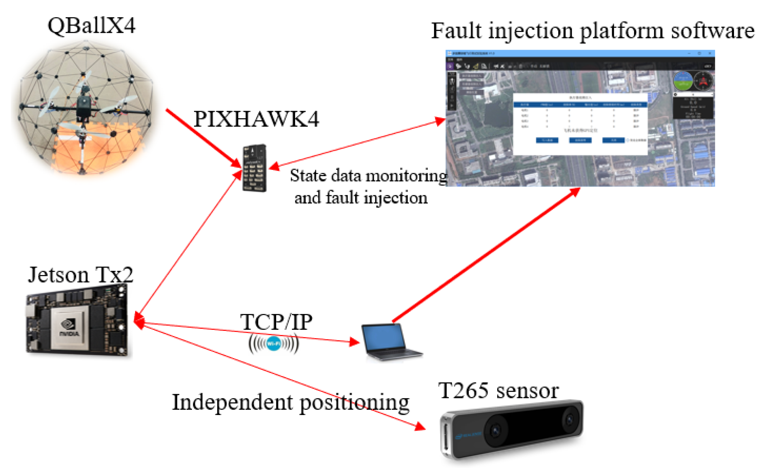
To facilitate the acquisition of the dynamic parameter changes of aircraft and design the FTAC algorithm, we tested and acquired QBall-X4 quadrotor UAV data using fault injection platform software. We assumed that the aircraft was a rigid body during the design process. The X-shaped framework was adopted. A general dynamic model of the quadrotor aircraft was thus constructed. Figure 1 shows the vehicle coordinate system and the inertial coordinate system of the quadrotor aircraft in an X-shaped configuration.
The control system of a quadrotor aircraft was powered by the brushless DC motor. The main task of the controller was to produce the desired aircraft attitude and position by changing the rotation speed of the four motors. Therefore, converting the rotation speed into force and moment of force was an essential part of the initial modeling of the multi-rotor aircraft [33]. The virtual control input of the aircraft U = u 1 u 2 u 3 u 4 T is introduced and defined as follows:
u 1 = f m , 1 + f m , 2 + f m , 3 + f m , 4 u 2 = f m , 2 + f m , 3 f m , 1 f m , 4 u 3 = f m , 1 + f m , 3 f m , 2 f m , 4 u 4 = f m , 1 + f m , 2 f m , 3 f m , 4 ,
where u 1 is the total lift provided by the four motors to the UAV; u 2 is the input control quantity of roll; u 3 is the input control quantity of pitch; u 4 is the input control quantity of yaw. The lift of each actuator is expressed as follows:
f m , i = c T , i · Ω i 2 i = 1 , 2 , 3 , 4 ,
where the parameter Ω i r a d / s is the angular velocity of the rotor an c T , i is the comprehensive thrust coefficient of a single oar.
To design the FTAC algorithm, we referred to the dynamic model of the multi-rotor UAV from [7,34]. The dynamic model of the quadrotor aircraft considered in this study used the following form:
ϕ ¨ = θ ˙ ψ ˙ J y y J z z J y y J z z J J x x + J m J m J J x x θ ˙ Ω r + l l J x x J x x u 2 K 4 l K 4 l J x x ϕ ˙ J x x ϕ ˙ θ ¨ = ψ ˙ ϕ ˙ J z z J x x J z z J x x J J y y + J m J m J J y y θ ˙ Ω r + l l J y y J y y u 3 K 5 l K 5 l J y y θ ˙ J y y θ ˙ ψ ¨ = ϕ ˙ θ ˙ J x x J y y J x x J y y J J z z + 1 1 J z z J z z u 3 K 6 K 6 J z z ψ ˙ J z z ψ ˙ x ¨ = cos ϕ sin θ cos ψ + sin ϕ sin ψ u 1 u 1 m m K 1 x ˙ K 1 x ˙ m m y ¨ = cos ϕ sin θ sin ψ sin ϕ cos ψ u 1 u 1 m m K 2 y ˙ K 2 y ˙ m m z ¨ = cos ϕ cos θ u 1 u 1 m m K 3 z ˙ K 3 z ˙ m g m g ,
where ϕ θ ψ correspond to the roll, pitch, and yaw angles of the UAV, respectively; x y z is the position of the UAV in the inertial coordinate system in each direction. The inertial matrix of the UAV is J = diag J x x J y y J z z ; J m and Ω r are the inertia and total residual angular velocity of the rotor, respectively; l is the distance between the central point of the actuator and rotor bearing; K i > 0 i = 1 , , 6 is the resistance coefficient; the aircraft’s mass is m; and the gravitational acceleration is g = 9 . 81   N / k g .

2.2. Problem Statement

In ideal situations, the multi-rotor UAV with a rigid structure can achieve a stable attitude when each rotor provides the same thrust. The posture and position of the aircraft can be changed by changing the thrust of the four rotors. Thus, based on the dynamic model of the system in Equation (3), the following affine nonlinear system was adopted for controller design:
x ˙ 1 ( t ) = x 2 ( t ) x ˙ 2 ( t ) = f x + g x · u i ( t ) y ( t ) = x 1 ( t ) ,
where the state variable x t = x x ˙ y y ˙ z z ˙ ϕ ϕ ˙ θ θ ˙ ψ ψ ˙ T can be obtained by measurement and calculation. The system modeling parameters were f x R 12 and g x R 12 × 4 .

2.2.1. Wind Disturbance Model of the Multi-Rotor UAV

The aerodynamic performance of the multi-rotor UAV with varying axle distance is usually disturbed by lateral wind along the direction of hovering and flying, and the aircraft stability may even be affected in severe cases. UAVs in agriculture, power line inspection, and other special operations usually work in windy environments (typical wind force of 4–7). In that case, the actuator needs to provide greater forces to produce a greater angular movement to maintain aircraft stability. Lei and Wang performed a wind disturbance study of a multi-rotor UAV in gentle wind [29]. Studies showed that the UAV undergoes significant horizontal drift due to lateral and horizontal winds. The lift provided by the actuator may be insufficient due to changes in air pressure in the propeller’s upper and lower surfaces, which further result in the change ub attitude angle. Here, the influence of gusts in different directions on the lift of each rotor was considered [29] and is given by the following equation:
f i = f w , i + f m , i i = 1 , 2 , 3 , 4 ,
where f w i is the extra thrust generated by the transverse air flow. To estimate the influence of the extra thrust on the dynamic model of the aircraft, we considered the induction wind velocity of each propeller [30]:
V i = f i 2 ρ S i ,
where ρ is the air density and S i is the cross-sectional area of the rotating propeller. Further, the thrust generated by each actuator is given by
f i = 2 ρ S i V i t o l V i m ,
where V i m is the induction wind velocity when the actuator is in normal operation and V i t o l is the total induction wind velocity of the actuator disturbed by gusts. Considering the influence of V i w gust disturbance, V i t o l is given by
V i t o l = V i w cos α + V i m 2 + V i w sin α 2 ,
where the angle α is the angle included between the direction of the transverse wind and the axial direction of the rotor. Based on the ratio between the velocity of the disturbing wind force and that of the wind generated by the propeller (the velocity of wind force 7 is 15 m/s and that of the wind generated by the propeller is above 200 m/s), the parameter r i = v i w v i w v i m v i m , r i 0 , 0.1 was defined. From Equations (6) and (7), the following was obtained:
f i = 2 ρ S i V i m 2 1 + r i 2 + 2 r i cos α ,
From this, we have
f w , i = f i f m , i = 2 ρ S i V i m 2 1 + r i 2 + 2 r i cos α 2 ρ S i V i m 2 2 ρ S i V i m 2 · r i .
Thus, the term d i w = 2 ρ S i V i m 2 · r i defines the wind force acting on each propeller. Since the torsion generated by rotor rotation was just the opposite to the aerodynamic resistance generated by rotor rotation, the aerodynamic resistance was defined as d i τ = ρ S i V i w 2 ρ S i V i w 2 2 2 Correspondingly, d w = d 1 t o l d 2 ϕ d 3 θ d 4 ψ T was the disturbance vector caused by gusts, which is defined as
d w = d 1 t o l d 2 ϕ d 3 θ d 4 ψ = d 1 w + d 2 w + d 3 w + d 4 w d 1 w + d 2 w + d 3 w + d 4 w m m d 2 w + d 3 w d 1 w d 4 w d 2 w + d 3 w d 1 w d 4 w J X X J X X d 1 w + d 3 w d 2 w d 4 w d 1 w + d 3 w d 2 w d 4 w J Y Y J Y Y d 1 τ + d 2 τ + d 3 τ + d 4 τ d 1 τ + d 2 τ + d 3 τ + d 4 τ J Z Z J Z Z ,

2.2.2. Actuator Fault Model

The four rotors supplied the relevant force and moment of force for the quadrotor aircraft to maintain hovering or other motion attitudes. In ideal situations, the motor’s rotational speed Ω i = Ω i , c and Ω i , c exhibited a linear relationship with the control quantity u i :
Ω i , c = k o , i u i + p i ,
where u i is the control quantity; k o , i and p i are the coefficients of normal quantities. However, in practice, a high temperature usually results from the motor’s rotation, and f m , i is no longer linearly related to Ω i 2 . When an aircraft collision happens, the rotors or propellers may be damaged, resulting in the deterioration of aircraft performance. The resultant multiplicative fault further impairs the actuator efficiency, while the additive fault causes the output drift of the actuator. Considering the above situations, the traction provided by a single actuator is expressed as
f m , i = c T , i · 1 b g a i n , i t k c , i t u i + c b i a s , i t + p i 2 ,
where b g a i n , i t is the gain fault 0 b g a i n , i t 1 , k c , i t is the continuous time function of the motor’s rotational speed vs. the actual controller signal u i , and c b i a s , i t is the additive fault of the actuator. The following actuator fault model is considered to facilitate the calculation:
u f , i = 1 b i t · k i t u i + c i t ,
where b i t = b g a i n , i t , k i t = k c , i t k o , i and c i t = c b i a s , i t k o , i . As for the attitude, position, and speed, the system state of a quadrotor aircraft can be calculated using the data from the gyroscope, magnetometer, and other sensors. Here, the system is described with a multi-input, multi-output (MIMO) nonlinear model. For the control system featured by the uncertainty model and actuator faults, and subject to external gust disturbance, the following affine nonlinear system was reconsidered for the design of the FTC algorithm:
x ˙ 1 = x 2 x ˙ 2 = f 0 ( x ) + Δ f x + g 0 ( x ) + Δ g x u f + d w y = x 1 ,
where u f = 1 b · k u + c , f ( x ) = f 0 ( x ) + Δ f x , g ( x ) = g 0 ( x ) + Δ g x , Δ f x and Δ g x are the uncertain terms of system modeling and d w ( t ) R 4 is the external wind disturbance of the system.

3. Fault-Tolerant Aircraft Controller Design

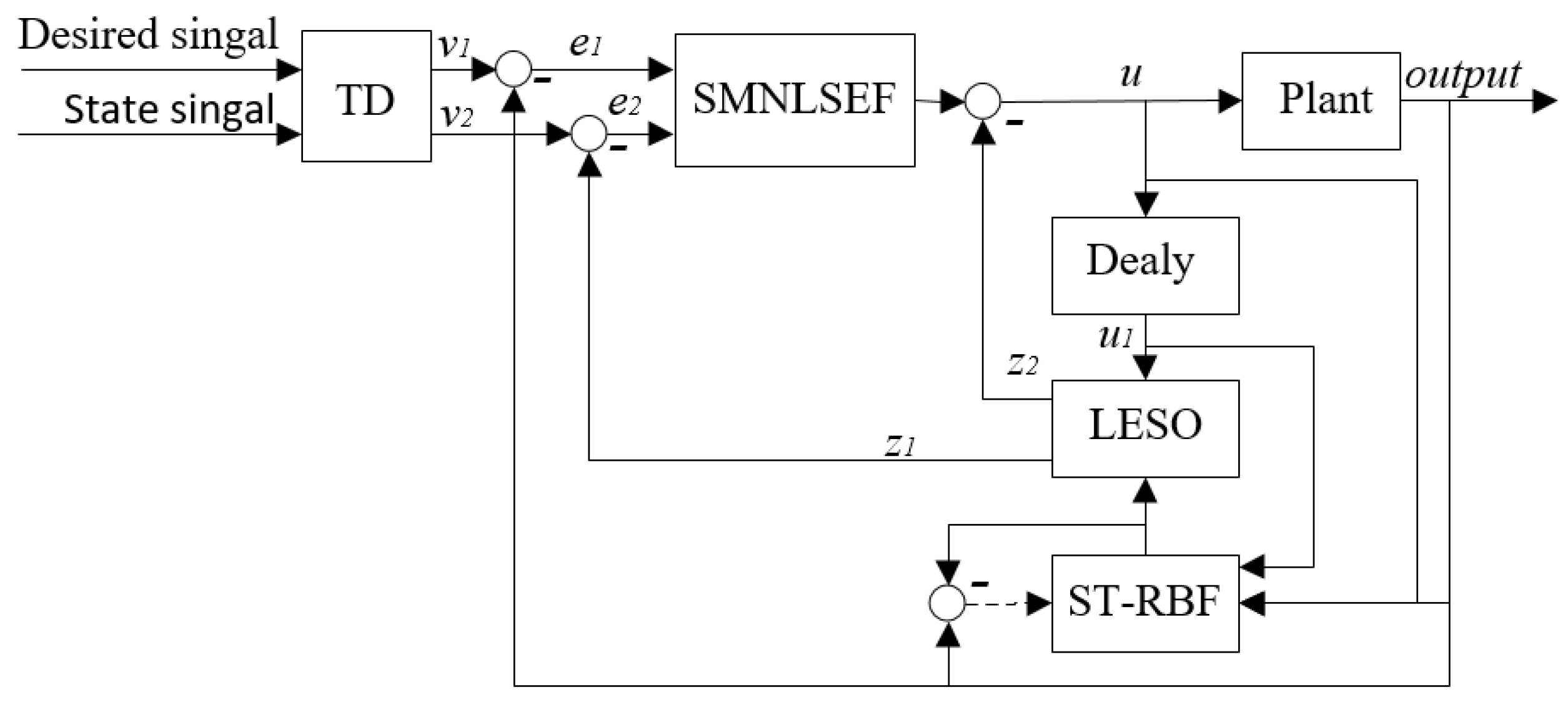
The active fault-tolerant controller designed in the present study combines an optimized reduced-order ESO with a novel spatiotemporally extended radial basis function neural network for estimating the uncertain parameters and replacing the original PD controller with a sliding-mode controller in the nonlinear state error feedback control section. The designed fault-tolerant controller addresses the tracking of the attitude expectation in the uncertainty model and the fault-tolerant control of the actuator in the event of the failure of the multi-rotor UAV. Figure 2 shows the FTAC design employed in the present study.

3.1. Adrc Controller Design

ADRC, first proposed by Han [35], is mainly composed of a tracking differentiator (TD), an extended state observer (ESO), and nonlinear state error feedback (NLSEF). In this study, based on the traditional ADRC, a reduced-order ESO was used to reduce the system delay, and a new RBFNN was used to estimate the system signal, while adapting to the occurrence of faults and interference.
A Tracking Differentiator (TD)
In transition design, the transition signal v 1 and its derivative v 2 are provided simultaneously. A TD offers better ability to solve the derivative of the reference signal ν . A second-order TD, if used in a controller, was designed as follows:
v ˙ 1 = h v 2 k v ˙ 2 = h f h a n v 1 v , v 2 , r 0 , h 0 ,
where v 1 is the tracking signal of v, v 2 is the derivative of v 1 , f h a n · is the optical time solution of the expected output signal ν 1 to converge to ν and ensures the fast convergence of the expected signals to the input signals without overshoot, h is the ultimate amplification coefficient of acceleration, and r 0 and h 0 affect the control accuracy of the system, where f h a n · = r 0 a d s i g n a · s a r 0 s i g n a . The corresponding parameters were designed as follows:
d = h 0 r 0 2 , a 0 = h 0 v 2 , y = v 1 + a 0 a 1 = d d + 8 y a 2 = a 0 + s i g n y a 1 d / 2 s y = s i g n y + d s i g n y d / 2 a = a 0 + y a 2 s y + a 2 s a = s i g n a + d s i g n a d / 2 .
B Extended State Observer (ESO)
The classical extended state observer treats the problem of system identification as a problem of disturbance suppression and treats the quantity of total disturbance as the state variable of the system. However, when there are faults or strong external disturbances in the system, full disturbance compensation can over-excite the system. Therefore, the application of the previous method is no longer able to solve practical problems and second-order ADRC is too costly in its application to accurately measure the attitude angle of the vehicle using instruments. Estimating angular signal values through sensor fusion introduces additional delays and uncertainties. Although using higher-order ESO provides more accurate data, it also results in a greater phase lag. This problem occurs due to the delay caused in the system due to the dynamic nature of the digital filters and actuators and the inability of conventional ADRCs to handle the situation effectively. Therefore, considering the above reasons, a reduced-order LESO was designed to reduce the phase lag problem of the ESO while providing reasonable disturbance compensation
e = z 1 y z ˙ 1 = z 2 + g 0 x u β 1 f a l e , υ 1 , τ ς x z ˙ 2 = β 2 f a l e , υ 2 , τ ,
where z 1 is used to estimate the attitude angular velocity, z 2 is used for an overall estimate of uncertainty and gust disturbance, and ς ^ x is used for estimating the additive fault of the actuator. β 1 and β 2 are the positive scalars. With the given observer bandwidth w 0 , β 1 = 2 w 0 , β 2 = w 0 2 . y is the system output. g 0 x is the input gain parameter of the system that can be derived. The saturation function f a l · , which was used to suppress dither, has the following form
f a l e , υ , τ = e υ sgn e , 0 < τ < e e e τ 1 υ τ 1 υ , 0 < e τ ,
where f a l · is a nonlinear function. When υ < 1 , the error and gain cannot be small or large simultaneously. Thus, when the error is small, the gain is large; when the error is large, the gain is small.
C Nonlinear State Error Feedback (NLSEF)
Usually, for the classical active disturbance rejection controller, the introduction of a nonlinear function f h a n · combined with a feedback controller in a nonlinear state error feedback link can result in better performance than linear control. The NLSEF is as follows:
e 1 = v 1 z 1 e 2 = v 2 z 2 u 0 = f h a n e 1 , c e 2 , r 1 , h 1 ,
where r 1 determines the upper and lower bounds of output, h 1 determines the width of the approximate smooth region between the bounds, and c is the damping factor.

3.2. Design of the Gradient Descent-Based Spatio-Temporal RBF Neural Network

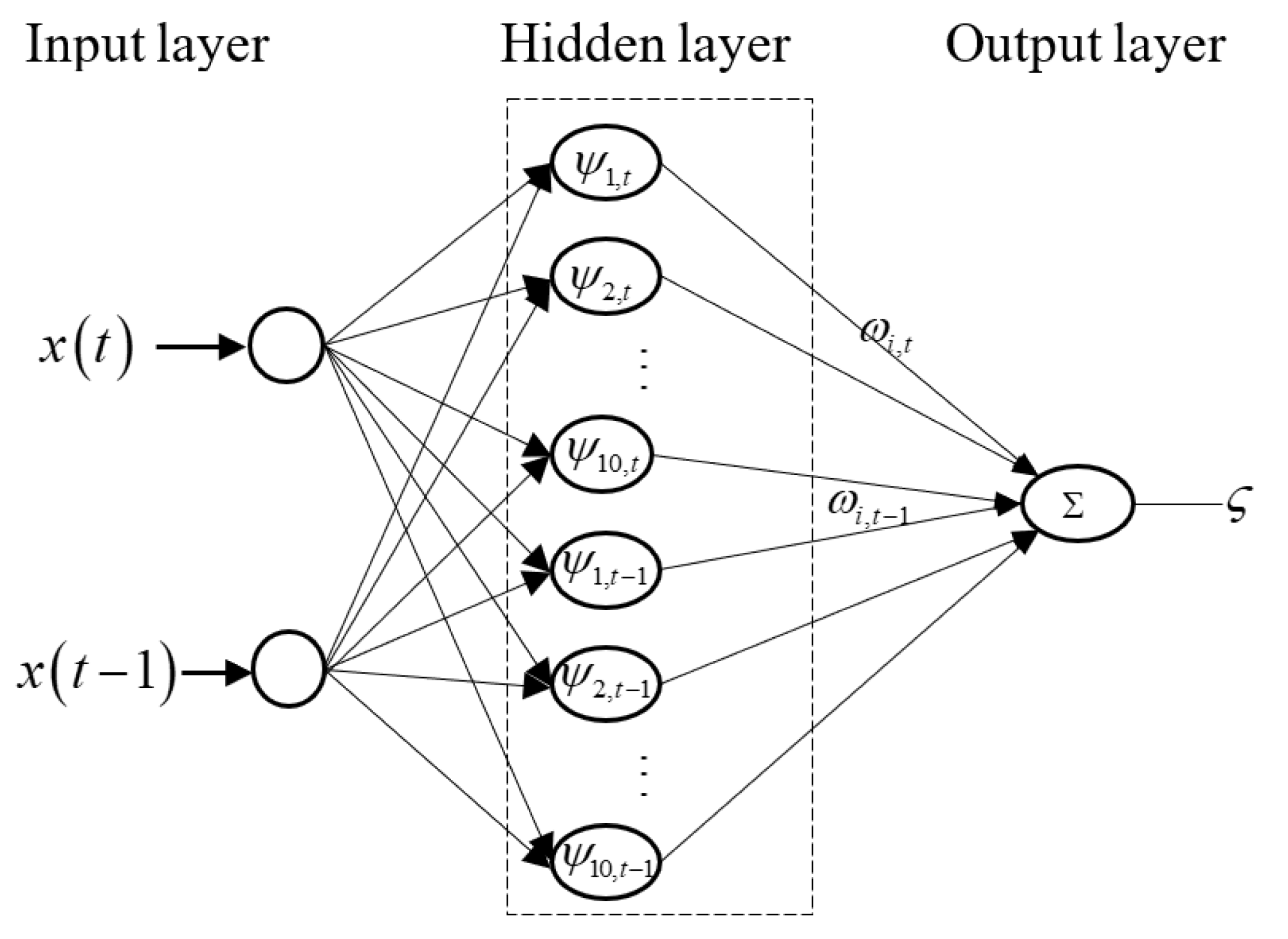
Radial basis function neural networks have many advantages in function approximation due to their simple structure, low computational complexity, and small required amount of data, and have arbitrary nonlinear mapping ability, which can be used to estimate uncertain parameters in nonlinear systems. Therefore, considering the nonlinear characteristics of the input and output data of the actuator fault model and wind disturbance model, radial basis neural networks were used in this study for parameter estimation. In contrast, conventional signal processing is mostly conducted with a single temporal or spatial signal. However, combining time-domain information with spatial information can provide more advantages for tracking target information. Referring to the ST-RBFNN used for chaotic time series prediction in [32], we propose a new RBFNN to estimate the actuator fault data and external disturbance data using its advantages in processing time dynamic characteristics and spatial nonlinear (complexity) signals, as shown in Figure 3.
A Spatio-Temporal RBF Neural Network (ST-RBFNN)
Initially, the input of the input layer was defined as x t x t 1 T , where x t R P , x t 1 R P , x t 1 is the sampled value of the previous moment of x t . x t = ϕ ψ θ ϕ ˙ θ ˙ ψ ˙ u 1 u 2 u 3 u 4 includes the attitude angle, angular velocity, and control law signal of the aircraft. Subsequently, when designing the nonlinear hidden layer, the temporal expansion was considered in the kernel space of the neural network in the signal processing. As a result, two parallel time layers corresponding to the input were designed for mapping the dynamic and nonlinear characteristics of the signal in time.The output layer adopted a linear combination output.
Consider ST-RBFNN for parameter estimation ς k . The expected value of the kth target signal can then be defined as d k . The error between the network estimate and the network expected value is δ k = d k ς k . The corresponding cost function is
ε k = 1 2 d k ς k 2 = 1 2 δ 2 k .
The overall mapping of the spatio-temporal radial basis function neural network adopted in this study was derived as follows:
ς k = i = 1 p t = 1 T w i , t k ψ x c i , t + b k ,
where ς : R P R 1 , w i , t k is the current weight value of the hidden layer to the output layer, p is the number of neurons in the hidden layer of the neural network, T is the cutoff time, c i , t R m 0 is the central value of the neural network, and b k is the deviation term for the output neuron. w i , t k and b k is updated with each iteration, and ψ i , t is the basis function of the hidden layer of the neural network. First, the common Gaussian kernel function was adopted by [36]
ψ i 1 x c i , t = exp x c i , t 2 σ 2 .
The gradient descent learning algorithm of RBFNN based on spatio-temporal extension was designed as follows:
w i , t k + 1 = w i , t k κ δ w i , t ε k ,
where w i , t k + 1 is the updated weight value, κ is the learning step length, δ w i , t is the regular derivative, and δ w i , t ε k can be estimated by the differential chain rule. To facilitate calculation, its partial derivative can be further taken as
δ w i , t ε k = ε k δ k × δ k ς k × ς k w i , t k = ψ x c i , t δ k .
Substituting Equation (25) into (24) yields
w i , t k + 1 = w i , t k + κ ψ i , t x , c i , t δ k .
Similarly, the learning rule of b k is
b k + 1 = b k + κ δ k .
B Design of a New Adaptive Kernel of ST-RBFNN
In order to further optimize ST-RBFNN’s need for an initial weight value, an improvement in the estimation precision of the RBFNN was needed. In this pursuit, Khan [37] introduced fusion cosine and a Euclidean distance metric that adjust the weights of an adaptive kernel that optimized the initial weights of ST-RBFNN in the process of anexperiment. Our method shows better results than the manual fusion of the kernels and can be represented as follows:
ψ i x , c i , t = γ 1 ψ i 1 x c i , t + γ 2 ψ i 2 x . c i , t ,
where the Gaussian kernel ψ i 1 x c i , t is the Euclidean kernel, and the cosine kernel ψ i 2 x . c i , t can be expressed as
ψ i 2 x . c i , t = x . c i , t ι + x · c i , t ,
where ι 0 + is a normal quantity. The parameters γ 1 and γ 2 in the new fusion kernel are the weight coefficients of the Euclidean kernel and the cosine kernel, respectively; and γ 1 k + γ 2 k = 1 . Therefore, the cost function can be redefined as
ε k = ε γ 1 k , γ 2 k = 1 2 d k ς k 2 .
In order to obtain the learning rules in the new kernel, the design method in Formula (26) was used to design the weight coefficient γ 1 and γ 2 gradient learning descent algorithm as follows:
γ 1 k + 1 = γ 1 k κ δ ψ 1 w k γ 2 k + 1 = γ 2 k κ δ ψ 2 w k .
Subsequently, chain differential differentiation yielded
δ ψ 1 ε k = ε k δ k δ k ς k ς k ψ i x , c i , t ψ i x , c i , t γ 1 k .
Accordingly, after taking the partial derivative of Formula (32), the update rule of γ 1 k was obtained as follows:
γ 1 k + 1 = γ 1 k + κ δ k w i , t k γ 1 k γ 2 k γ 1 k γ 1 k + γ 2 k 2 × ψ i 1 x c i , t ψ i 2 x . c i , t .
Similarly, the update rule of γ 2 k is
γ 2 k + 1 = γ 2 k + κ δ k w i , t k γ 1 k γ 2 k γ 2 k γ 1 k + γ 2 k 2 × ψ i 2 x . c i , t ψ i 1 x c i , t .

3.3. Design of Fault-Tolerant Aircraft Control Law

To improve the system robustness, we introduced sliding-mode control into the nonlinear feedback component of the ADRC. For a given system model, we chose the fast-moving sliding-mode surface as follows:
s t = e 2 t c e 1 t ,
where e 2 t = e ˙ 1 t , e 1 t = x 1 t x d t , c > 0 satisfies the Hurwitz stability criteria.
To simplify the calculation, according to Equations (13) and (14), we defined the nonlinear function ς 1 x = Δ f x + g 0 ( x ) c + Δ g x c containing uncertain parameters of the system model and actuator deviation faults. We also defined the nonlinear function ς 2 x = Δ g x g 0 ( x ) b · k Δ g x b · k containing the actuator gain faults and physical characteristic parameters of the actuator. The system was rewritten in the following form:
x ˙ 1 = x 2 x ˙ 2 = f 0 ( x ) + ς 1 ( x ) + g 0 ( x ) u + ς 2 ( x ) u + d w y = x 1 .
Uncertain terms account for a very small proportion of system modeling. Particularly, a system with virtual control input hardly changes as long as the aircraft is not destroyed. Therefore, the following inequality holds in the uncertain terms of the system modeling:
g 0 x Δ g x g 0 x g x Δ g x g x .
It is easy to obtain Δ g x Δ g x g x g x 0.5 , 2 . The parameter τ = ς 2 ς 2 g 0 g 0 was defined, and the following inequality was derived:
τ = Δ g x g 0 ( x ) b · υ Δ g x b · υ g 0 ( x ) < 1 1 b · υ + Δ g x 1 b · υ g 0 ( x ) .
Because 0 < 1 b · υ 1 , τ < 1 . To facilitate the design of the system control rate, positive constants ζ 1 an ζ 2 were defined, and these are in the form of d w t ζ 1 . The following inequalities exist for parameter λ :
λ 1 , ζ ^ 2 > 0 λ 1 , ζ ^ 2 0 .
The following adaptive law was designed for some parameters involved in the control law as
ζ ^ ˙ 1 = χ 1 s ζ ^ ˙ 2 = χ 2 ϖ s ς ^ ˙ 1 = φ 1 s ς ^ ˙ 2 = τ φ 2 s .
where χ 1 , χ 2 , φ 1 , and φ 2 are positive constants. The parameters ς ^ 1 and ς ^ 2 are the calculated outputs of the neural network and ς ˜ 1 = ς 1 ς ^ 1 , ς ˜ 2 = ς 2 ς ^ 2 . Let us define ϖ > 0 , ϖ = x ¨ d + c e 1 f 0 ( x ) ζ ^ 1 sgn s ς ^ 1 ς ˜ 2 . According to Equation (28), the following control rate was defined for a nonlinear system with actuator faults
u = 1 g 0 ( x ) x ¨ d + c e 1 f 0 ( x ) ζ ^ 1 sgn s ς ^ 1 λ ϑ sgn s ι sgn s
where ϑ = ζ ^ 2 ϖ and ι are positive constants.

4. Stability Verification

We chose the Lyapunov function to validate the effectiveness of the FTAC algorithm that combined the new ADRC and the spatio-temporal RBF neural network:
V = 1 2 s 2 + 1 2 χ 1 1 ζ ˜ 1 2 + 1 2 1 τ χ 2 1 ζ ˜ 2 2 + 1 2 φ 1 1 ς ˜ 1 2 + 1 2 φ 2 1 ς ˜ 2 2 ,
where ζ ˜ i = ζ i ζ ^ i . By referencing Formula (41), the derivative of the Lyapunov function with respect to time can be obtained as follows:
V ˙ = s s ˙ χ 1 1 ζ ˜ 1 ^ ˙ ζ 1 1 τ χ 2 1 ζ ˜ 2 ^ ˙ ζ 2 φ 1 1 ς ˜ 1 ^ ˙ ς 1 φ 2 1 ς ˜ 2 ^ ˙ ς 2 = s s ˙ ζ ˜ 1 s 1 τ ζ ˜ 2 ϖ s ς ˜ 1 s ς ˜ 2 τ s
The derivative with respect to the sliding mode surface can be expressed as
s ˙ = e ˙ 2 c e ˙ 1 = x 2 x ¨ d c e 1 = f 0 ( x ) + ς 1 ( x ) + g 0 ( x ) u + ς 2 ( x ) u + d w x ¨ d c e 1 .
Substituting the control law from Equation (41) into Equation (44) and replacing the control law concerning the known parameter g 0 ( x ) yield
s ˙ = f 0 ( x ) + ς 1 ( x ) + ς 2 ( x ) u + d w x ¨ d c e 1 + g 0 ( x ) 1 g 0 ( x ) x ¨ d + c e 1 f 0 ( x ) ζ ^ 1 sgn s ς ^ 1 λ ϑ sgn s ι sgn s = ς ˜ 1 ( x ) + ς 2 ( x ) u + d w ζ ^ 1 sgn s λ ϑ sgn s ι sgn s .
Furthermore, the derivative of the Lyapunov function can be extended to
V ˙ = s ς 2 ( x ) u + s d w s ζ ^ 1 sgn s s λ ϑ sgn s s ι sgn s ζ ˜ 1 s 1 τ ζ ˜ 2 ϖ s ς ˜ 2 τ s = s ς 2 ( x ) u + s d w ζ ^ 1 s λ ϑ s ι s ζ ˜ 1 s 1 τ ζ ˜ 2 ϖ s ς ˜ 2 τ s .
From the formula, τ < 1 can be obtained. Therefore, according to the parameter τ = ς 2 ς 2 g 0 g 0 , for part s ς 2 ( x ) u of Formula (46), the following relation can be derived:
s ς 2 ( x ) u = s ς 2 1 g 0 x ¨ d + c e 1 f 0 ( x ) ζ ^ 1 sgn s ς ^ 1 λ ϑ sgn s ι sgn s s ς 2 g 0 x ¨ d + c e 1 f 0 ( x ) ζ ^ 1 sgn s ς ^ 1 λ ϑ sgn s ι sgn s τ s x ¨ d + c e 1 f 0 ( x ) ζ ^ 1 sgn s ς ^ 1 ς ˜ 2 + ς ˜ 2 + λ ϑ + ι τ s ϖ + ς ˜ 2 + λ ϑ + ι .
So, for Formula (46), we obtain
V ˙ τ s ϖ + ς ˜ 2 + λ ϑ + ι + s d w ζ ^ 1 s λ ϑ s ι s ζ ˜ 1 s 1 τ ζ ˜ 2 ϖ s ς ˜ 2 τ s .
Because ζ 2 = 1 1 1 τ 1 τ , d w s ζ 1 s 0 , ϑ = ζ ^ 2 ϖ , it follows that
V ˙ τ ϖ s + τ λ ϑ s + τ ι s + s d w ζ ^ 1 s λ ϑ s ι s ζ ˜ 1 s 1 τ ζ ˜ 2 ϖ s τ ϖ s 1 τ λ 1 ζ ^ 2 ϖ s 1 τ ζ ^ 2 ϖ s + τ ι s + s d w ζ 1 s ι s 1 τ ζ ˜ 2 ϖ s 1 τ λ 1 ζ ^ 2 ϖ s 1 τ ϖ s 1 τ ι s .
Since τ < 1 , 1 τ > 0 , according to the inequality relation in Equation (39), it is true that when ζ ^ 2 > 0 , there is V ˙ < 0 ; and when ζ ^ 2 0 , λ 1 , the derivative of Lyapunov function V ˙ < 0 still holds.Therefore, the system is asymptotically stable.

5. Simulation Results

As shown in Figure 4, to verify the effectiveness of the proposed fault-tolerant control algorithm, we employed the QBall-X4 UAV platform for UAV data acquisition and flight verification, and the platform could effectively achieve the injection of real actuator fault data. In order to realistically analyze the control performance of the proposed fault-tolerant control algorithm, we collected real flight data in the experimental phase, which mainly included the state data ϕ , ψ , θ , ϕ ˙ , θ ˙ , ψ ˙ , control signal u 1 , u 2 , u 3 , u 4 , and the desired signal ϕ r e f , ψ r e f , θ r e f of the remote control in manual control mode. In this paper, we mainly present the performance curve of the attitude controller to verify and demonstrate the effectiveness of the designed algorithm, where the selected roller subsystem can be expressed as follows:
ϕ ¨ = θ ˙ ψ ˙ J y y J z z J x x + ς 1 x + l J x x u 2 + ς 2 x u 2 + d w y = ϕ .
where f 0 = θ ˙ ψ ˙ J y y J z z J x x , g 0 = l J x x , J x x = 0.01194 kg· m 2 , J y y = 0.01194 kg· m 2 , J z z = 0.02181 kg· m 2 , l = 0.2 m, and the parameters ς 1 and ς 2 are the parts of the system for which parameter fusion estimation is required.
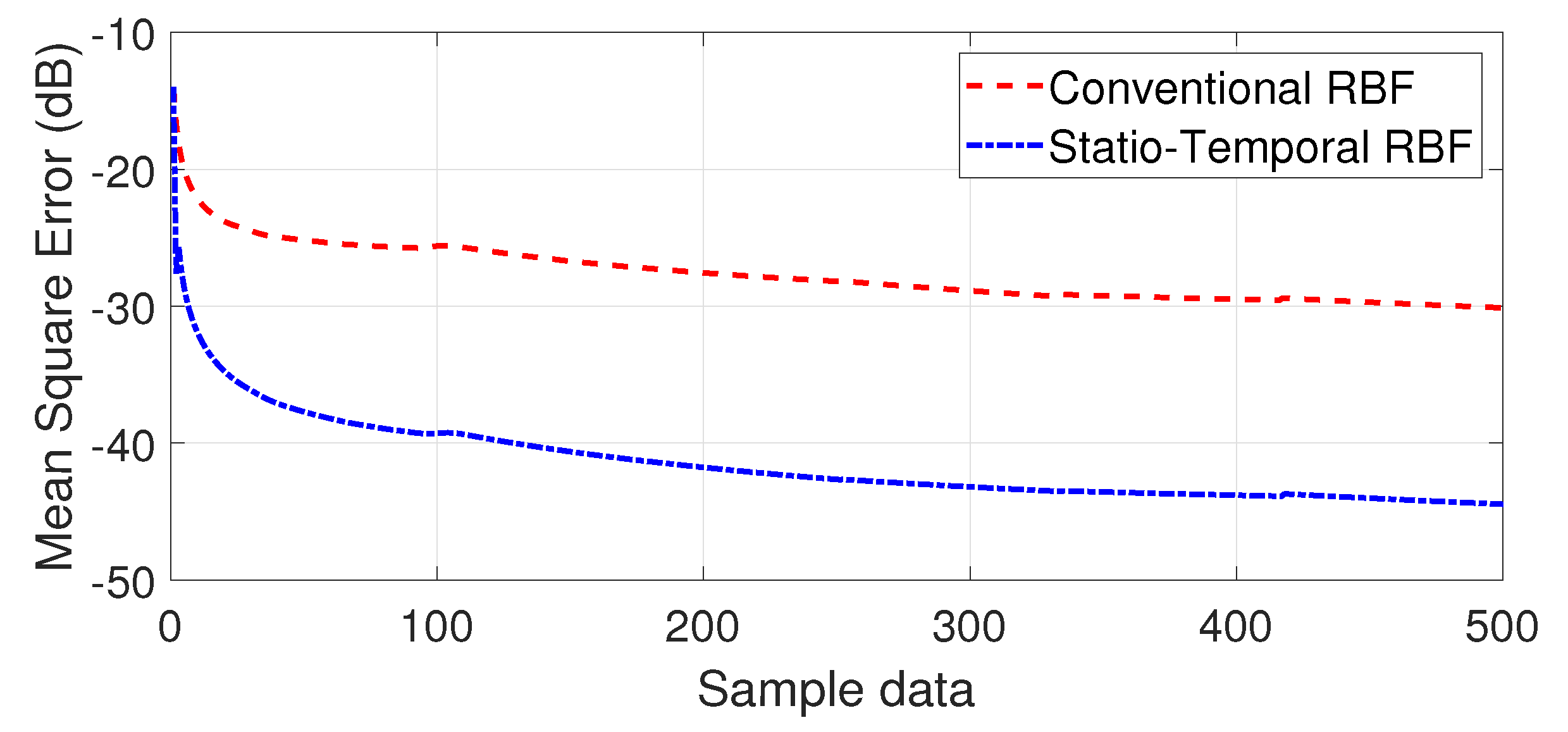
In ST-RBFNN, the state variables were used as the input for model training, and the collected data were then used as parameters and for subsequent calculations. The raw dataset was a combination of the standard flight data and the fault data from a fault injection test UAV. In this study, each set of experimental data was collected at a sampling frequency of 1 ms, and each set contained 60,000 consecutive time series of data, with the training data and test data divided in a 5:1 ratio. The neural network was then iteratively trained according to the weight update rule of the novel ST-RBFNN designed in Section 3. Finally, the trained network model was embedded in the controller in the experiments. As shown in Figure 5, given a set of 500 sample data for validation and comparison, the average mean squared error of the proposed RBFNN based on the new adaptive kernel was found to be better than that of the conventional RBFNN.
According to Figure 6 and Figure 7, ST-RBFNN tracked the predicted sample data more accurately than the conventional RBFNN, with a tracking error close to zero.
In the validation phase of the effectiveness of the fault-tolerant controller, the pitch and roll systems selected in this study were compared with the experimental results. To validate the effectiveness of the proposed fault-tolerant controller, a multi-rotor UAV with modeling uncertainties was selected in this study. Additionally, three flight simulation scenarios were considered for the qualitative analysis of the control performance of the controller.
  • Scenario 1: Testing the flight effects of an active disturbance rejection, fault-tolerant controller based on a spatio-temporal RBF predictive neural network in the absence of external wind gust disturbances and actuator failures.
  • Scenario 2: Numerical simulation of a horizontal wind gust disturbance of 3–9 m/s. The controller’s performance was analyzed on the basis of the effect of the aircraft in a sustained wind disturbance scenario. The performance of the controller was analyzed on the basis of the effects of the aircraft in a wind disturbance situation that lasts for a period of time.
  • Scenario 3: In the gust-disturbed environment of Scenario 2, UAV Motors 1–4 were further injected with specified fault values via the UAV’s fault-tolerant control system, corresponding to the gain fault and deviation fault data shown in Table 1. At the same time, an additional 80 dB Gaussian white noise disturbance was added to the fault data during the experiment.
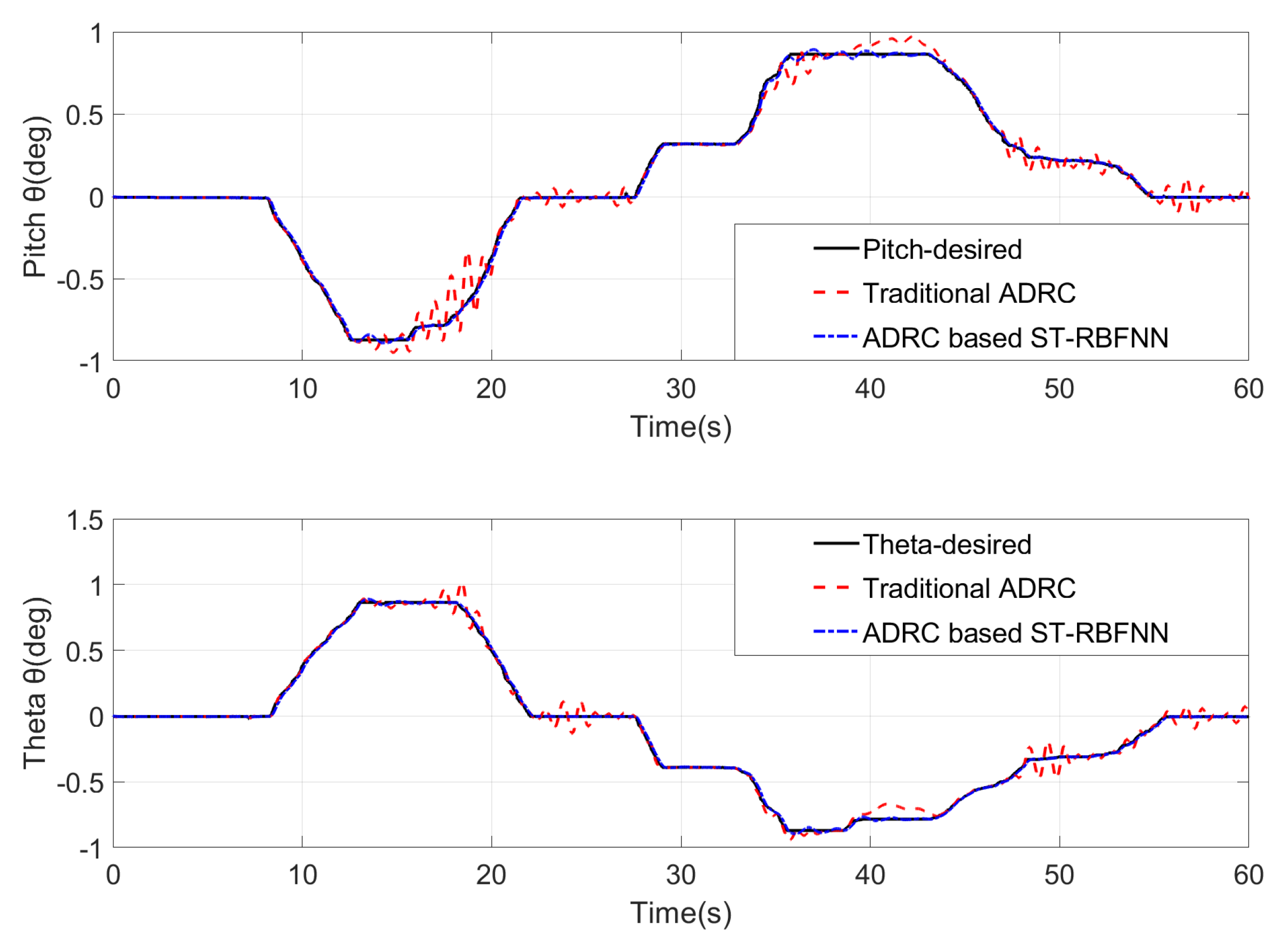
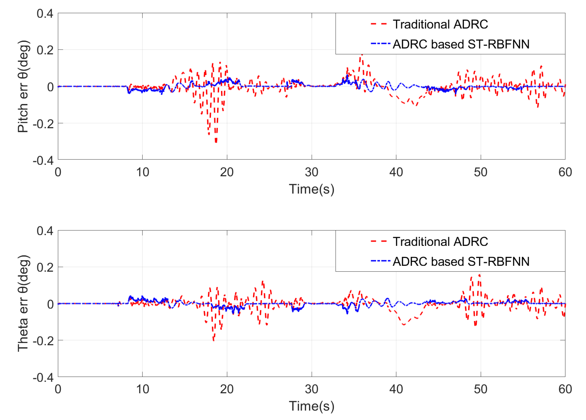
The experimental data for Scenario 1 are shown in Figure 8 and Figure 9. Comparing the performance of the traditional ADRC and the ST-RBFNN ADRC controller, we observed that both the flight controller designed in this paper and the traditional self-impeding control were able to achieve good attitude tracking control. However, in the experiment, when the remote control offered a large change in control command, the adjustment time of traditional ADRC was longer and the tracking error was larger than that of the fault-tolerant flight controller, and resulted in the oscillation of aircraft attitude.
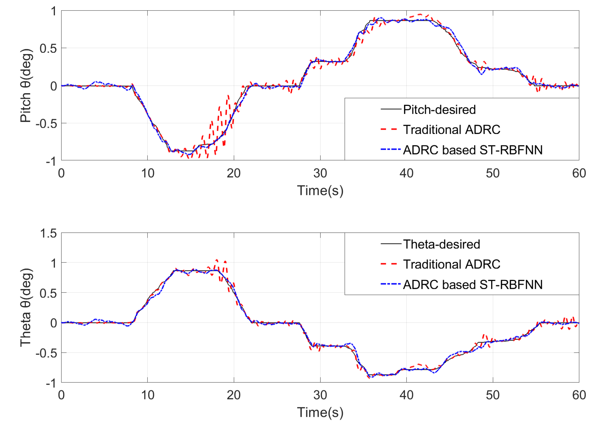
Figure 10 and Figure 11 show the effect of the control of the aircraft attitude during the gust disturbance in Scenario 2. In the test experiment, we simulated a gust disturbance lasting 7 s, with a wind speed of 3–7 m/s on the aircraft at 14 s. A gust disturbance lasting 4 s with a wind speed of 5–9 m/s was simulated for the aircraft at 43 s. We observed that the aircraft based on active disturbance rejection control preserved good tracking performance in the presence of disturbances. Table 2 shows the controller performance parameters obtained for a given unit step of signal perturbation in Scenario 1 and Scenario 2 experiments. The fault-tolerant controller designed in this paper exhibited more stable tracking performance, a shorter adjustment time, and less overshoot than the traditional active disturbance rejection controller.
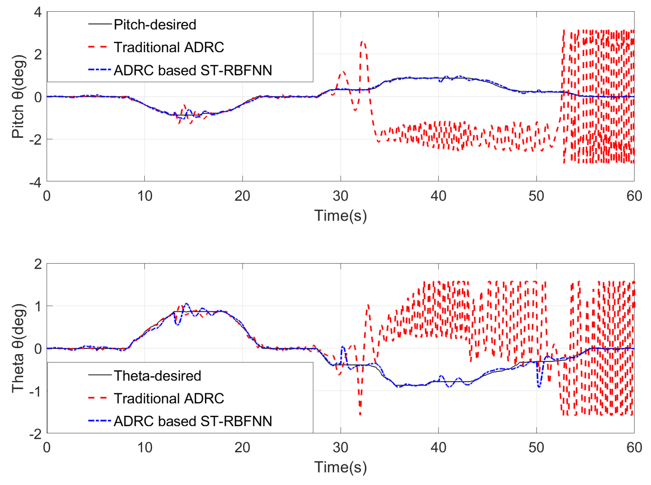
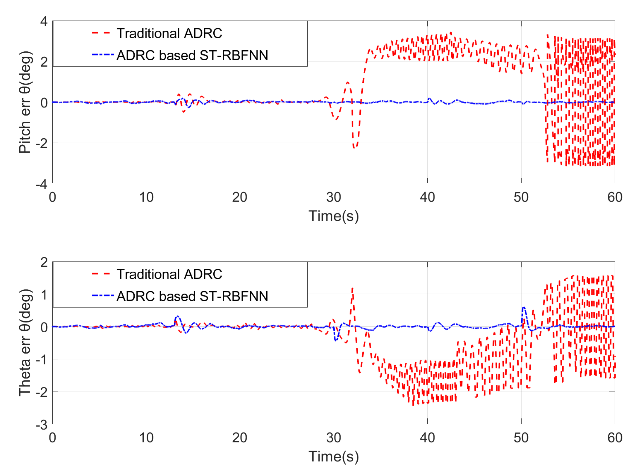
Figure 12 and Figure 13 show the change in the attitude of the aircraft in Scenario 3 when the fault was injected. In the experiment, we injected a gain fault of 0.05 into Motor 1 at 5 s and a deviation fault of 30 into Motor 2. After 13 s, Motor 1 was injected with a gain fault of 0.1 and Motor 2 with a deviation fault of 50. At the 30 s mark, both Motors 1 and 2 were injected with a gain fault of 0.15 and a deviation fault of 60. After 40 s, Motors 1–3 were simultaneously injected with the fault values in Table 1. At 50 s, all four motors were simultaneously injected with the fault data from Table 1.
Comparing the tracking effects of the fault-tolerant controller in Figure 12 and Figure 13, it is clear that in the first two fault injections, the conventional active disturbance rejection controller achieved stable tracking control by treating the actuator faults as external disturbances. However, from 30 s onward, when a number of actuators experienced both gain and deviation faults, the conventional active disturbance rejection controller was already unstable, yet the fault-tolerant control proposed in this paper was still able to achieve stable control.
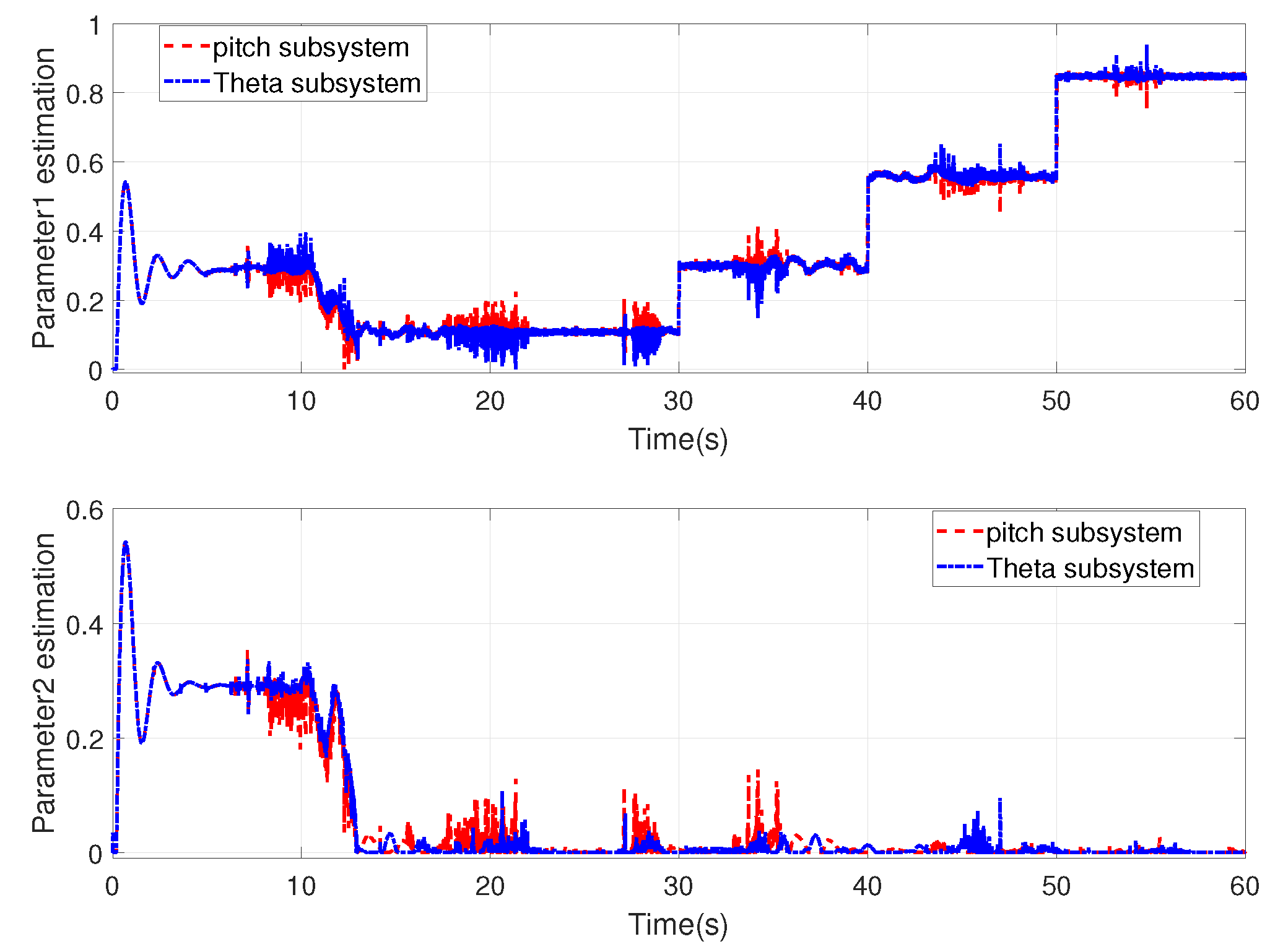
Figure 14 shows the estimated values of parameters ς 1 and ς 2 for the pitch and roll controllers, respectively, in the event of an actuator failure. It can be seen that the proposed fault-tolerant controller provided a parameter complement to the attitude control during the take-off phase of the aircraft, allowing fast and accurate estimation of fault data in the event of an actuator fault.

6. Conclusions

The flight stability of an aircraft may be adversely influenced by external disturbances and actuator faults. When performing tasks in different environments, the aircraft is considerably affected by the climate, including temperature, humidity, and air pressure. Aircraft collision may also happen in unknown flight environments. All of these adverse factors adversely impact the actuator or sensors and induce uncertain changes in the aircraft’s model parameters. To address the above problems, we integrated an ADRC controller with a spatio-temporal RBF neural network to construct an FTAC scheme. This RBF neural network was capable of the online estimation of uncertain terms in the system model. In addition, the optimal gradient descent method reduced the controller’s calculation amount and achieved a faster response. A combination with the sliding-mode controller further improved the attitude stability of the aircraft. The experimental results showed that the FTAC can maintain stable flight in finite time, thus verifiying the reliability of the proposed FTAC. Therefore, the method proposed in this paper can be used to control a multi-rotor UAV with actuator failure, gust disturbance, and model uncertainty. Furthermore, the experimental data showed that in the case of increasing actuator fault values, the system’s estimates of parameters due to model uncertainty continually increased, which indirectly led to a decrease in the controller’s tracking performance. Due to the loss of the actuator power caused by the large fault value and the different minimum lift required for different masses of aircraft, the control effect of the controller on different control objects was not identical. Therefore, the fault-tolerant controller proposed in this paper does not fully satisfy all the use scenarios. As a result, certain improvements are still needed in this area.

Author Contributions

Conceptualization, L.H., J.Z., D.L. and X.X.; methodology, L.H., J.Z., D.L. and X.X.; validation, L.H., D.L. and J.Z.; formal analysis, L.H. and D.L.; investigation, L.H.; resources, L.H.; data curation, L.H. and D.L.; writing—original draft preparation, L.H.; writing—review and editing, D.L.; visualization, X.X.; supervision, J.Z.; project administration, L.H.; funding acquisition, J.Z. All authors have read and agreed to the published version of the manuscript.

Funding

This research was funded by the Interdisciplinary Project of Yangzhou University Crop Science Special Zone, grant number yzuxk202007; and the Natural Science Research Project of Universities in Jiangsu Province (20KJB470032).

Institutional Review Board Statement

Not applicable.

Informed Consent Statement

Not applicable.

Data Availability Statement

Data sharing not applicable.

Acknowledgments

The authors would like to thank the Crop Science Special Zone Interdisciplinary Program of Yangzhou University for financial support and the Advanced Vehicle Health Management Laboratory of Nanjing University of Aeronautics and Astronautics for equipment support.

Conflicts of Interest

The authors declare no conflict of interest.

Abbreviations

The following abbreviations are used in this manuscript:
ADRCActive Disturbance Rejection Control
UAVUnmanned Aerial Vehicles
FTACFault-Tolerant Aircraft Control
RBFRadial Basis Function
FTCFault-Tolerant Control
DCDirect-Current
ESOExtended State Observer
SMNLSEFSliding Mode Nonlinear State Error Feedback
ST-RBFNNSpatio-Temporal Radial Basis Function Neural Network

References

  1. Radoglou-Grammatikis, P.; Sarigiannidis, P.; Lagkas, T.; Moscholios, I. Ioannis Moscholios, A compilation of UAV applications for precision agriculture. Comput. Netw. 2020, 172, 1286–1389. [Google Scholar] [CrossRef]
  2. Jiang, F.; Pourpanah, F.; Hao, Q. Design, Implementation, and Evaluation of a Neural-Network-Based Quadcopter UAV System. IEEE Trans. Ind. Electron. 2019, 67, 2076–2085. [Google Scholar] [CrossRef]
  3. Wang, X.; Sun, H.; Long, Y.; Zheng, L.; Liu, H.; Li, M. Development of visualization system for agricultural UAV crop growth information collection. IFAC-PapersOnLine 2018, 51, 631–636. [Google Scholar] [CrossRef]
  4. Barisic, A.; Car, M.; Bogdan, S. Vision-based system for a real-time detection and following of UAV. In Proceedings of the Workshop on Research, Education and Development of Unmanned Aerial Systems, Cranfield, UK, 25–27 November 2019; pp. 156–159. [Google Scholar]
  5. Fritzel, T.; Steiner, H.J.; Strauß, R. Advances in the Development of an Industrial UAV for Large-Scale Near-Field Antenna Measurements. In Proceedings of the 2019 13th European Conference on Antennas and Propagation, Krakow, Poland, 31 March–5 April 2019; pp. 1–3. [Google Scholar]
  6. Ding, M.; Tang, L.; Zhou, L.; Wang, X.; Weng, Z.; Qu, J. W Band Mini-SAR on Multi Rotor UAV Platform. In Proceedings of the International Conference on Electronic Information and Communication Technology, Harbin, China, 20–22 January 2019; pp. 416–418. [Google Scholar]
  7. Zheng, E.H.; Xiong, J.J.; Luo, J.L. Second order sliding mode control for a quadrotor UAV. ISA Trans. 2014, 53, 1350–1356. [Google Scholar] [CrossRef] [PubMed]
  8. Dávila, J.; Salazar, S. Robust control of an uncertain UAV via high-order sliding mode compensation. IFAC-PapersOnLine 2017, 50, 11553–11558. [Google Scholar] [CrossRef]
  9. Tang, Y.R.; Xiao, X.; Li, Y. Nonlinear dynamic modeling and hybrid control design with dynamic compensator for a small-scale UAV quadrotor. Measurement 2017, 109, 51–64. [Google Scholar] [CrossRef]
  10. Mofid, O.; Mobayen, S. Adaptive sliding mode control for finite-time stability of quad-rotor UAVs with parametric uncertainties. ISA Trans. 2018, 72, 1–14. [Google Scholar] [CrossRef]
  11. Cheng, D.; Ning, W.; Meng, J.E. Self-organizing adaptive robust fuzzy neural attitude tracking control of a quadrotor. In Proceedings of the Chinese Control Conference, Chengdu, China, 27–29 July 2016; pp. 10724–10729. [Google Scholar]
  12. Zhang, Y.; Zhang, X.; Chen, Z. A novel control scheme for quadrotor UAV based upon active disturbance rejection control. Aeros. Sci. Technol. 2018, 79, 601–609. [Google Scholar] [CrossRef]
  13. Tan, J.; Fan, Y.; Yan, P.; Wang, C.; Feng, H. Sliding mode fault tolerant control for unmanned aerial vehicle with sensor and actuator faults. Sensors 2019, 19, 643. [Google Scholar] [CrossRef] [PubMed] [Green Version]
  14. Nguyen, D.T.; Saussié, D.; Saydy, L. Robust self-scheduled fault-tolerant control of a quadrotor UAV. IFAC-PapersOnLine 2017, 50, 5761–5767. [Google Scholar] [CrossRef]
  15. Wang, X.; Sun, S.; van Kampen, E.J. Quadrotor fault tolerant incremental sliding mode control driven by sliding mode disturbance observers. Aerosp. Sci. Technol. 2019, 87, 417–430. [Google Scholar] [CrossRef] [Green Version]
  16. Vural, S.Y.; Dasdemir, J.; Hajiyev, C. Passive fault tolerant lateral controller design for an UAV. IFAC-PapersOnLine 2018, 51, 446–451. [Google Scholar] [CrossRef]
  17. Yu, X.; Zhang, Y. Design of passive fault-tolerant flight controller against actuator failures. Chin. J. Aeronaut. 2015, 28, 180–190. [Google Scholar] [CrossRef] [Green Version]
  18. Zhong, Y.; Zhang, Y.; Zhang, W.; Zuo, J.; Zhan, H. Robust actuator fault detection and diagnosis for a quadrotor UAV with external disturbances. IEEE Access 2018, 6, 48169–48180. [Google Scholar] [CrossRef]
  19. Song, Z.; Sun, K. Adaptive compensation control for attitude adjustment of quad-rotor unmanned aerial vehicle. ISA Trans. 2017, 69, 242–255. [Google Scholar] [CrossRef] [PubMed]
  20. Li, Y.; Tong, S.; Liu, L.; Feng, G. Adaptive output-feedback control design with prescribed performance for switched nonlinear systems. Automatica 2017, 80, 225–231. [Google Scholar] [CrossRef]
  21. Wang, B.; Shen, Y.; Zhang, Y. Active fault-tolerant control for a quadrotor helicopter against actuator faults and model uncertainties. Aerosp. Sci. Technol. 2020, 99, 105745. [Google Scholar] [CrossRef]
  22. Jiang, H.; Zhang, H.; Liu, Y.; Han, J. Neural-network-based control scheme for a class of nonlinear systems with actuator faults via data-driven reinforcement learning method. Neurocomputing 2017, 239, 1–8. [Google Scholar] [CrossRef]
  23. Zeghlache, S.; Djerioui, A.; Benyettou, L.; Benslimane, T.; Mekki, H.; Bouguerra, A. Fault tolerant control for modified quadrotor via adaptive type-2 fuzzy backstepping subject to actuator faults. ISA Trans. 2019, 95, 330–345. [Google Scholar] [CrossRef]
  24. Wang, B.; Zhang, Y. An adaptive fault-tolerant sliding mode control allocation scheme for multirotor helicopter subject to simultaneous actuator faults. IEEE Trans. Ind. Electron. 2017, 65, 4227–4236. [Google Scholar] [CrossRef] [Green Version]
  25. Boche, A.; Farges, J.L.; De Plinval, H. Reconfiguration control method for multiple actuator faults on UAV. IFAC-PapersOnLine 2017, 50, 12691–12697. [Google Scholar] [CrossRef]
  26. Lijia, C.; Yu, T.; Guo, Z. Adaptive observer-based fault detection and active tolerant control for unmanned aerial vehicles attitude system. IFAC-PapersOnLine 2019, 52, 47–52. [Google Scholar] [CrossRef]
  27. Zhou, L.; Ma, L.; Wang, J. Fault tolerant control for a class of nonlinear system based on active disturbance rejection control and rbf neural networks. In Proceedings of the 36th Chinese Control Conference (CCC), Dalian, China, 26–28 July 2017; pp. 7321–7326. [Google Scholar]
  28. Wang, S.; Han, Y.; Chen, J.; Du, N.; Pan, Y.; Wang, G.; Zhang, Z.; Zheng, Y. Flight safety strategy analysis of the plant protection UAV. IFAC-PapersOnLine 2018, 51, 262–267. [Google Scholar] [CrossRef]
  29. Lei, Y.; Wang, H. Aerodynamic performance of a quadrotor MAV considering the horizontal wind. IEEE Access 2020, 8, 109421–109428. [Google Scholar] [CrossRef]
  30. Guo, Y.; Jiang, B.; Zhang, Y. A novel robust attitude control for quadrotor aircraft subject to actuator faults and wind gusts. IEEE/CAA J. Autom. Sin. 2017, 5, 292–300. [Google Scholar] [CrossRef]
  31. Wang, Z.; Zhao, H.; Duan, D.; Jiao, Y.; Li, J. Application of improved active disturbance rejection control algorithm in tilt quad rotor. Chin. J. Aeronaut. 2020, 33, 1625–1641. [Google Scholar]
  32. Sadiq, A.; Ibrahim, M.S.; Usman, M.; Zubair, M.; Khan, S. Chaotic time series prediction using spatio-temporal rbf neural networks. In Proceedings of the International Conference on Emerging Trends in Engineering, Sciences and Technology, Karachi, Pakistan, 21–22 December 2018; pp. 1–5. [Google Scholar]
  33. Bouabdallah, S.; Siegwart, R. Backstepping and sliding-mode techniques applied to an indoor micro quadrotor. In Proceedings of the 2005 IEEE International Conference on Robotics and Automation, Barcelona, Spain, 18–22 April 2005; Volume 50, pp. 2247–2252. [Google Scholar]
  34. Xiong, J.J.; Zhang, G.B. Global fast dynamic terminal sliding mode control for a quadrotor UAV. ISA Trans. 2017, 66, 233–240. [Google Scholar] [CrossRef]
  35. Han, J. From PID to active disturbance rejection control. IEEE Trans. Ind. Electron. 2009, 56, 900–906. [Google Scholar] [CrossRef]
  36. Wettschereck, D.; Dietterich, T. Improving the performance of radial basis function networks by learning center locations. NIPS 1991, 4, 1133–1140. [Google Scholar]
  37. Khan, S.; Naseem, I.; Togneri, R.; Bennamoun, M. A novel adaptive kernel for the rbf neural networks. Circuits Syst. Signal Process. 2017, 36, 1639–1653. [Google Scholar] [CrossRef] [Green Version]
Figure 1. Reference coordinate system of the quadrotor.
Applsci 11 04084 g001
Figure 2. Fault-tolerant aircraft controller.
Applsci 11 04084 g002
Figure 3. Structure of ST-RBFNN.
Applsci 11 04084 g003
Figure 4. Schematic diagram of the experimental system.
Applsci 11 04084 g004
Figure 5. Testing MSE curves of ST−RBF and conventional RBF.
Applsci 11 04084 g005
Figure 6. Prediction results of ST−RBF and conventional RBF.
Applsci 11 04084 g006
Figure 7. Prediction error of ST−RBF and conventional RBF.
Applsci 11 04084 g007
Figure 8. Flight attitude of quadrotor in Scenario 1.
Applsci 11 04084 g008
Figure 9. Flight attitude tracking error of quadrotor in Scenario 1.
Applsci 11 04084 g009
Figure 10. Flight attitude when external interference occurred in Scenario 2.
Applsci 11 04084 g010
Figure 11. Flight attitude tracking error when external interference occurred in Scenario 2.
Applsci 11 04084 g011
Figure 12. Flight attitude when actuator failure occurred in Scenario 3.
Applsci 11 04084 g012
Figure 13. Flight attitude tracking error when actuator failure occurred in Scenario 3.
Applsci 11 04084 g013
Figure 14. Estimation of parameters 1 and 2.
Applsci 11 04084 g014
Table 1. Actuator fault data of the quadrotor.
Fault Generation Time (s)Gain Fault ValueDeviation Fault Values (pwm: 0–150)
5 s5%30
13 s10%50
30 s15%60
40 s15%100
50 s20%150
Table 2. Controller performance index.
ControlerSettling TimeOvershootAngle Error
Traditional ADRC in Scenario 12.3 s12.3%0.3°
ST-RBFNN ADRC in Scenario 11.5 s0%0.04°
Traditional ADRC in Scenario 23.2 s15.6%0.4°
ST-RBFNN ADRC in Scenario 22.2 s5.3%0.12°
Publisher’s Note: MDPI stays neutral with regard to jurisdictional claims in published maps and institutional affiliations.