Abstract
Passive grinding is a new rail grinding strategy. In this work, the influence of grinding pressure on the removal behaviors of rail material in passive grinding was investigated by using a self-designed passive grinding simulator. Meanwhile, the surface morphology of the rail and grinding wheel were observed, and the grinding force and temperature were measured during the experiment. Results show that the increase of grinding pressure leads to the rise of rail removal rate, i.e., grinding efficiency, surface roughness, residual stress, grinding force and grinding temperature. Inversely, the enhancement of grinding pressure and grinding force will reduce the grinding ratio, which indicates that service life of grinding wheel decreases. The debris presents dissimilar morphology under different grinding pressure, which reflects the distinction in grinding process. Therefore, for rail passive grinding, the appropriate grinding pressure should be selected to balance the grinding quality and the use of grinding wheel.
1. Introduction
As an effective method to eliminate rail defects such as ripples and rolling contact fatigue cracks [1,2] and to reprofile the rail head that affects the safety of train-running [3], rail grinding has become a routine maintenance operation for the railway network [4]. The rail grinding can be divided into corrective operation and preventative operation [5,6]. The operational difference between them is that the cutting depth of preventative operation is shallower than corrective operation [7]. Thus, the preventative operation can more effectively prolong the rail service life and reduce the operating costs [8], because only the rail surface is polished periodically before rail defects appear in order to nip the disease in the bud [9]. The customary way of rail grinding is to use the end face of the grinding wheel to grind the rail. The grinding wheels are driven by the motor to actively rotate with the grinding train on the rail [10]. The maintenance speed of this grinding method is in the range from 3 to 20 km/h with grinding train speed [11]. However, in preventive grinding, since only a small amount of metal is required to be removed from the rail surface, this rail maintenance strategy with slow train speed and high grinding volume shows low maintenance efficiency. It is not conducive to the application of rail preventive maintenance.
Recently, the scale of High-Speed Railway has become larger and larger in the world, and the spacing interval of departure time is shorter and shorter [12]. As a result, the “skylight time” of maintenance operation is ever-shortening; therefore, the rail grinding speed and efficiency is critical [13]. How to grind the longest possible railway line in the shortest possible time has become the focus of rail preventive grinding. The rail high-speed grinding technique, involving “non-driven” grinding wheels that remove a very shallow depth of cut, has been introduced in the preventative operation for High-Speed Railway by VOSSLOH company [14]. In this case, the grinding train speed can reach a range from 60 to 80 km/h, and it is also beneficial for noise control [15]. This high-speed grinding for railroad maintenance is not the traditional “HSG” with high linear speed of grinding wheels but means that the grinding train can run at high speed on the rail. Thus, rail grinding can be completed quickly.
The emergence of rail high-speed grinding is of great significance. Not only can it significantly improve the grinding efficiency because of the high working speed, but it can also extend the service life of the rails because of the lower grinding volume of passive grinding compared to the frequently-used active grinding. These can help reduce railway operations and maintenance costs and contribute to the development of preventative grinding in railroads. Because of “non-driven’” grinding wheels, the rail high-speed grinding is also known as “passive grinding”. The passive grinding process is significantly different from the active grinding way. The grinding wheels are rotated freely without driven power, and the axial direction is set at an angle with the rail surface [16]. Under the motion and pressure of the grinding train, the grinding wheels roll forward along the rail surface; hence, the grinding process of grinding wheels on rail surface is realized [17]. In this way, the grinding train can run at high speed while grinding the rail. This new rail grinding process has just been applied. However, there are still many problems worth studying.
Many research works reported that grinding parameters have a great effect on grinding efficiency, surface roughness, consumption of grinding wheel, and so on. Uhlmann et al. [18] investigated the influence of rail grinding process parameters on rail surface. This study verified the correlation between rail grinding process parameters and grinding results. The effects of grinding parameters on the processing results were described qualitatively. For active grinding wheels, Zhang et al. [19] developed rail grinding wheels using three grit sizes of F10, F16 and F30. The grinding differences with different abrasive sizes for steel rails were investigated. Wang et al. [20] studied the effects of abrasive types and grinding wheel hardness on rail grinding behavior. It was found that the increase in grinding wheel hardness improved the grinding quality, but the grinding efficiency decreased. Zirconium corundum abrasive was better than brown fused alumina for rail grinding. For online grinding of rails, Wu et al. [21] constructed an experimental method for vertical grinding and investigated the effect of grinding pressure on the grinding effect of rails and grinding materials. The influence of grinding load on grinding process was verified by analyzing the grinding debris and the material morphology before and after grinding. It is considered that the grinding material could show the best performance of rail grinding when the experimental load is less than 150 N. Pereverzev et al. [22] built a mathematical model for the grinding force in cylindrical plunge grinding. Although this model of cylindrical grinding also belongs to active grinding, it is more applicable to the study of passive grinding compared to the model of end-face grinding. This study obtained a formula to calculate the stock removal rate and established the adequacy of the mathematical model of the grinding force in cylindrical plunge grinding. It provides a great reference for the analysis of passive grinding.
However, due to the lower material removal amount in passive grinding compared with active grinding under conventional conditions, the passive grinding reflect its application advantages in rail maintenance grinding. Its scope of application is relatively limited. Therefore, the published studies are all about active grinding, while passive grinding has been rarely studied. For the new passive grinding, it is important to research the effect of grinding parameters on material removal from rail head [23,24]. During the passive grinding process as stated above, the rotation of grinding wheel and material removal from rail head may strongly relate to working pressure-force acting on grinding wheel, speed of grinding train, angle between the axial direction of grinding wheel and the rail surface and grinding performance of grinding wheel. Currently, for zirconia alumina corundum resin grinding wheel, the angle of 45° between the axial direction of grinding wheel and the rail surface and the speed of 60~80 km/h of grinding train are used in rail grinding operation. As a consequence, the grinding pressure has become the most important parameter for the passive grinding operation. Therefore, for passive grinding, the effect of grinding pressure on behavior of material removal from the rail head should be first considered in study.
In this work, a self-designed passive grinding simulator was used to investigate the effect of grinding pressure on behavior of material removal from rail head material. It is a creative idea for passive grinding tests. This experimental equipment can be used not only for testing passive grinding parameters to provide reference for the parameter setting of passive grinding but also for the development and testing of passive grinding wheels. Meanwhile, the effect of grinding pressure on consumption of passive grinding wheel was explored. The results will contribute to re-understanding the passive grinding characteristics and developing passive grinding process specifications.
2. Materials and Methods
2.1. Self-Designed Passive Grinding Simulator
A passive grinding simulator was self-designed based on the tool grinder as shown in Figure 1a, and its grinding schematic is shown in Figure 1b. The passive grinding process of contact mode is shown in Figure 1c, and the combination of rail sample is shown in Figure 1d. The test device is primarily composed of the part of round rail sample and the support part of the passive grinding wheel. The main characteristic of the test equipment is that the grinding wheel (4) had no active rotating power, while, the round rail specimen (3) rotated actively driven by the spindle of the motor (2) providing the rotating power. The grinding wheel (4) was fixed on one side of the L-form locating plate (6) at a certain angle through the bearing bar and bearing bracket (5), which could rotate freely without resistance under the action of external forces. The grinding angle of the grinding wheel (4) on the rail specimen (3) was fixed at 45°. In rail grinding experiment, the rail specimen (3) rotated at a certain linear speed to simulate the speed of the grinding train. The air compressor and storage tank (11) were used to provide pressure load by driving the sliding based (14) to move through the pneumatic cylinder (12) to make the grinding wheel (4) contact with the round rail specimen (3) and apply a pressure load. In this way, the relative motion between them was produced and the grinding was carried out.
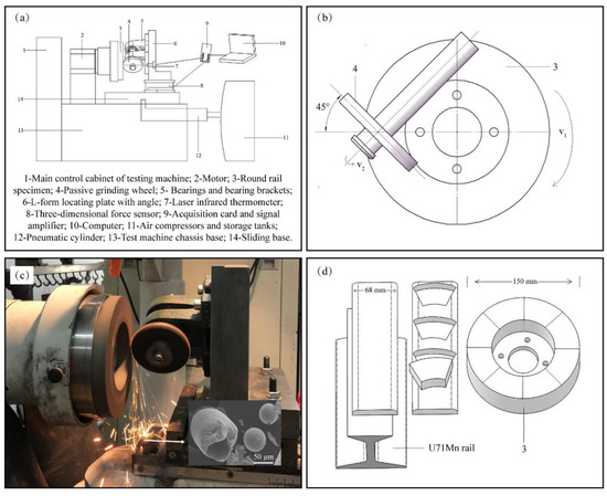
Figure 1.
(a) Structure diagram of the self-designed passive grinding simulator, (b) grinding schematic diagram of rail sample and grinding wheel, (c) grinding process of passive grinding test and (d) combination of rail sample.
In order to test the grinding temperature of the passive grinding area in the test, a temperature measuring system was designed, and its structure is shown in Figure 2. Figure 2a shows the side sectional view of the rail sample, and Figure 2b shows the bottom substrate diagram. The NiCr-NiSi thermocouple (Ⅳ) wrapped with insulating film clamped between the rail specimens for insulation and was fixed with mica fixture (Ⅱ). Since the rail specimen (Ⅰ) was rotating during the test, two conductive copper rings (Ⅶ) fixed on the insulation ring (Ⅵ) were embedded on the top of the bottom substrate. The copper brush (Ⅷ) was always in contact with the conductive ring (Ⅶ) so that the electrical signal generated by the thermocouple (Ⅳ) could be continuously received while grinding. In addition, an infrared thermometer (Ⅹ) was installed externally during grinding to assist in recording the grinding temperature for verification purposes.
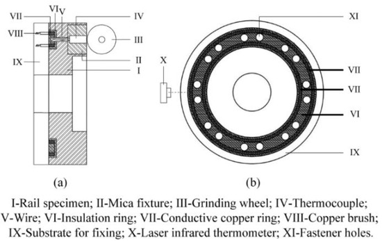
Figure 2.
Temperature measurement system structure, (a) internal structure diagram of rail sample, (b) bottom substrate diagram.
During the grinding test process, the main control cabinet of the test machine (1) controlled the rail rotation speed, contact pressure and grinding time. The test machine chassis base (13) was used to support the whole grinding mechanism and collect grinding debris. The three-dimensional mechanical sensor (8) was fixed between the L-form locating plate (6) and the sliding base (14), and the laser infrared thermometer (7) was fixed on the lateral side of the L-form locating plate (6). The test equipment could record mechanical and temperature signals by acquisition card and signal amplifier (9) during grinding, so that the grinding pressure, the grinding force along the direction of the grinding wheel and the grinding temperature at the grinding contact point could be recorded synchronously at the computer terminal (10). Since the grinding wheel and the supporting part of the grinding wheel had a dead weight, the tangential component of gravity direction was measured and zeroed before each test.
2.2. Experimental Materials
In this work, the material was cut from rail head of steel U71Mn, which had been widely used in railways. The chemical composition and mechanical properties of steel U71Mn are listed in Table 1 and Table 2 [25]. The standard rail head width is 68 mm, which was machined into 8 identical rings and assembled into the disc sample with a diameter of 150 mm. In order to explore the influence of grinding pressure on the behaviors of material removal from rail, the surface of all disc samples was machined to the same roughness.

Table 1.
Chemical compositions (wt%) of U71Mn rail steel.
Table 2.
Mechanical properties of U71Mn rail steel.
The self-designed grinding wheels were used in this work. The main components of the grinding wheel are given in Table 3. The new grinding wheels developed independently had been verified by online trial. The size of passive grinding wheel used in the experiment with an outer diameter of 80 mm, an inner diameter of 10 mm and a thickness of 10 mm was made to match the size of the rail sample.
Table 3.
Composition of passive grinding wheel.
2.3. Grinding Test
The grinding test was employed on the self-designed passive grinding simulator. The parameters were designed according to the actual passive grinding conditions of the VOSSLOH “HSG-2” grinding train [14]. The speed of 80 km/h and the rotation angle of 45° are commonly used, and the depth of cut is around 0.05 mm per pass [12,15]. Therefore, the rotational speed of the rail sample was designated as 2831 r/min to simulate the speed of the grinding train of 80 km/h. The purpose of this paper is to study the influence of grinding pressure on behavior of material removal from rail by grinding wheel. The setting of the grinding pressure depends on the pressure load, which is another most important parameter related to force loaded on grinding wheel and its contact area on rail. As shown in Figure 3, the contact arc length (lc) between grinding wheel and rail sample relates to the depth of cut (αp) and equivalent diameter of the grinding wheel (d), i.e., lc=(αp·d)½ [26]. If the cutting geometric-contact length of the grinding wheel is approximately regarded as a straight line and the grinding depth is set to a uniform 0.05 mm, the contact area between the grinding wheel and rail can be calculated. According to the size of the test grinding wheel (80 × 10 × 10 mm) and actual grinding wheel (160 × 74 × 35 mm) for rail grinding, the test contact area is about 1/10 of the actual rail grinding; thus, the test load should be about 1/10 of the actual rail grinding, and then the same contact pressure load between the test and actual rail grinding can be ensured. In light of the pressure load of 2000 N used commonly in actual rail grinding [27,28], six groups with different loading force were employed in this work and they were sequentially numbered as A to F. The tests were carried out under the same conditions of rail velocity of 22 m/s, wheel deflection angle of 45° and grinding time of 30 s. The grinding loads for groups A to F were set to 120 N, 160 N, 200 N, 240 N, 280 N and 320 N, which represent the actual grinding loads from 1200 N to 3200 N, respectively.
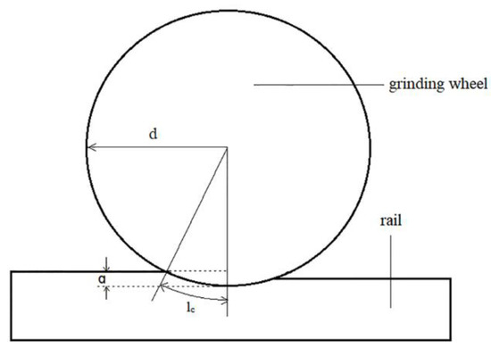
Figure 3.
2D diagram of passive grinding cutting process.
It should be noted that this simulation of passive grinding cannot completely recreate the process of rail high-speed grinding due to the limitation that the grinding wheel cannot work continuously on the straight rail. It results in the difference between the specific values of the test results and the practical results of high-speed rail grinding, such as the surface roughness of the rail after grinding. However, it does not affect the study of the influence of passive grinding parameters on the trend of grinding results and the grinding test of passive grinding wheels because this simulation focuses on passive grinding behavior. In addition, in order to make the grinding test results more visible, the test time of passive grinding was extended. In practical application, the grinding time of rail high-speed grinding is slightly less than 30 s.
All experiments were conducted in the same room environment (temperature: 21 °C, humidity: 60%). Each group of experiments utilized new grinding wheels and was repeated 6 times to obtain the final experimental results. Meanwhile, the grinding force and grinding temperature were synchronously recorded by mechanical sensors and infrared thermometers during the test. Before the test, anhydrous ethanol was used to clean the surface of the rail sample and grinding wheels to ensure that the influence of impurities was eliminated. The rail samples and the grinding wheels were weighed before and after the grinding test. The mass loss of grinding per unit time for the rail sample was defined as the material removal ratio of rail or grinding efficiency, and the ratio of grinding mass loss between rail and grinding wheel was defined as the grinding ratio.
The information of the main devices used to construct the grinding mechanism is as follows: tool grinder (BDM-901C, DiMontega, Beijing, China), force sensor (VC121D-50, Viste, Shenzhen, China) and infrared thermometer (TA8605, TASI, Suzhou, China). The signals acquired from the test were transformed into digital signals through a converter and stored in computer through a Labview program. The surface topography was observed by Ultra-fine digital microscope (VHX-7000, KEYENCE, Osaka, Japan). The surface roughness of rail before and after grinding test was measured and recorded by 3D optical surface profilometer (Ze Gage TM, Zygo, Middletown, CT, USA). The surface residual stress was inspected via the X-ray (Proto iXRD, LaSalle, ON, Canada). In addition, the grinding debris was observed via SEM and analyzed by EDS (S-3400 N, Hitachi, Tokyo, Japan) and XRD (D/MAX-2500, Rigaku, Shishima, Japan).
3. Results
3.1. Grinding Efficiency and Grinding Ratio
According to the mass loss of the rail sample and the grinding wheel before and after grinding under different pressure loads, the grinding efficiency and grinding ratio of the grinding wheel to the rail sample were calculated; the results are shown in Figure 4. For the passive grinding, the grinding efficiency significantly improves with the increase of grinding load. This phenomenon is consistent with the traditional grinding principle of active grinding. With the increase of grinding pressure, the local contact pressure load on each abrasive intensifies, and more abrasives are involved in the cutting process. Therefore, the material removal from the rail is enhanced, and the grinding efficiency is improved. The purpose of rail polishing is to remove defects or rail fatigue layer from the rail surface, and the grinding efficiency directly determines the material removal from the rail. From this viewpoint, the higher grinding pressure load is beneficial to increase grinding efficiency.
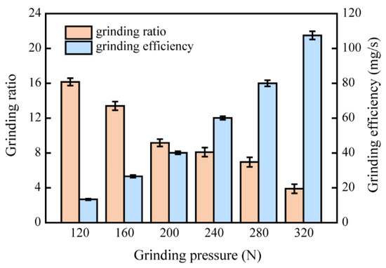
Figure 4.
Grinding efficiency and grinding ratio of the grinding wheel to the rail sample under different pressure.
However, the grinding pressure load also has a significant impact on the grinding ratio of the grinding wheel. The grinding ratio reflects the durability of the grinding wheel. The grinding ratio decreases markedly with the increase of grinding load, which indicates that the service life of the grinding wheel reduces. The rail grinding does consider not only grinding efficiency but also the life of the grinding tool, hence an appropriate grinding pressure load to balance the grinding efficiency and the service life of grinding wheel should be considered.
As shown in Figure 4, when the grinding load is lower than 200 N, the grinding ratio decreases rapidly with the increase of load; the decreasing trend of grinding ratio slows down when the pressure load increases to the range of 200 N to 280 N. However, when the grinding load further increases over 280 N, the grinding ratio drops sharply once again. At the grinding load of 320 N, the grinding ratio decreases to approximately half that of 240 N. Accordingly, a balance between grinding efficiency and service life of the grinding wheel can be obtained by appropriate grinding load in the range of 200 N to 240 N.
It is universally acknowledged that the grinding pressure also affects the morphology, residual stress and temperature of rail surface in the grinding process. As a consequence, to optimize the grinding parameter of the grinding pressure load, the effect of grinding pressure on the roughness, residual stress and grinding temperature of the grinding rail surface should be considered as well.
3.2. Morphology and Roughness of Rail Surface Grinding Zone
The surface quality of rails is one of the most important factors in evaluating rail maintenance, in which the morphology and roughness of rail surface are the most direct manifestations of rail surface quality to affect the safety and stability of train operation. The optical morphologies of rail surface before and after passive grinding are shown in Figure 5. Before grinding, the rail surface was processed into the same surface topography and exhibited regular groove topographies as shown in Figure 5a. After grinding, the grooves were removed and replaced by fine grinding marks. It is found that grinding pressure has some effect on grinding morphology. As the grinding pressure load was 120 N, some coarse grooves that existed before grinding could not be completely removed, and there were some scattered shallow grinding marks on the rail surface, as shown in Figure 5b. When the grinding pressure load increased to 160 N, the grinding marks filled on the rail contact surface, while the grinding marks distributed uniformly. Less shallow grinding marks regions and common grinding marks regions could be found on grinding surface as shown in Figure 5c. With the increase of load to 200 N, the obvious plastic flow and flat could be observed as shown in Figure 5d. The plastic flow areas are caused by the accumulation of steel on both sides of the grinding mark by abrasive plow rail, while the abrasive leaves flat areas between the grinding marks after cutting the rail with the discharge of rail debris [29]. Moreover, when grinding pressure was further enhanced, the grinding marks were coarsened and some wear regions appeared on the rail surface as shown in Figure 5e–g. Combined with the grinding test, it can be found that due to the rotation of the grinding wheel with the movement of the rail and the deflection angle of the grinding wheel, the grinding action of grinding wheels on the rail is greatly affected by pressure during the grinding process. Insufficient pressure under low grinding pressure load will lead to grinding unevenness, resulting in a small area of shallow grinding marks. Excessive pressure load will generate heavy cutting of rail by grinding wheel, which may cause surface wear. The results illustrate that the increase of passive grinding pressure load will improve the grinding quality stability but over a certain limit will raise the possibility of wear on the rail surface, which is not conducive to grinding. The results can be confirmed by observation carried out on an optical 3D surface profilometer.
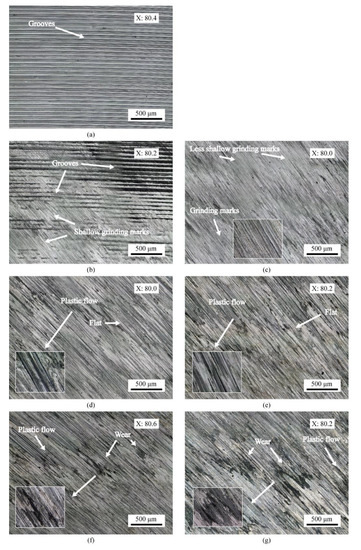
Figure 5.
OM of the ground rail surfaces: (a) before grinding, (b) 120 N, (c)160 N, (d) 200 N, (e) 240 N, (f) 280 N, (g) 320 N.
Figure 6 shows the 3D surface topographies and profiles of the rail sample before grinding and after passive grinding under different loads. In Figure 6, the Sa and Sz are surface roughness and maximum topographic depth, respectively. Meanwhile, the grinding surface topographies of the rail are visually represented by the profile lines in the figures. According to the results shown in Figure 6, the surface roughness and topographic depth of the rails before and after grinding were quantitatively analyzed, and the results after repeated test and data statistics are shown in Figure 7. Based on Figure 6 and Figure 7, the grinding pressure load could greatly affect the roughness and topographic depth of rail surface after passive grinding. Although the grooves are still present on the rail surface when the test grinding load is 120 N as shown in Figure 6b, the roughness and topographic depth of rail surface observably decrease from 2.613 μm and 19.283 μm to 0.459 μm and 5.146 μm as shown in Figure 7. With the grinding load raised to 160 N, the groove defects are completely removed from the rail surface as shown in Figure 6c, and the surface roughness and topographic depth further reduce to 0.210 μm and 3.515 μm as shown in Figure 7. While the grinding load is over 160 N, the elevation in the expression of surface roughness and topographic depth increases with the increase of grinding load. However, when the load gets to 240 N, the trend is broken. The surface roughness keeps increasing, while the depth did not change much when the load increased from 240 N to 280 N. Furthermore, as the grinding load gets to 320 N, the surface roughness does not change much but the topographic depth increases greatly. From Figure 5, the wear areas appear on the rail grinding surface when the grinding load is over 280 N. The worn part increases the grinding marks depth significantly, as shown in Figure 7. These show that the excessive pressure load will not significantly improve the grinding effectiveness.
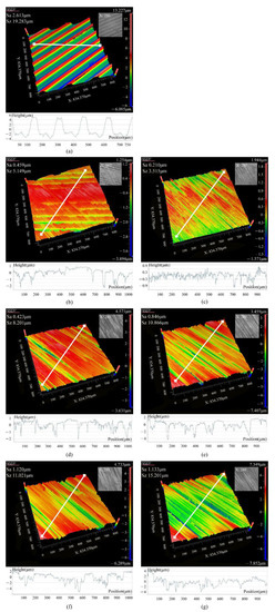
Figure 6.
3D surface topographies and profiles: (a) before grinding, (b) 120 N, (c)160 N, (d) 200 N, (e) 240 N, (f) 280 N, (g) 320 N.
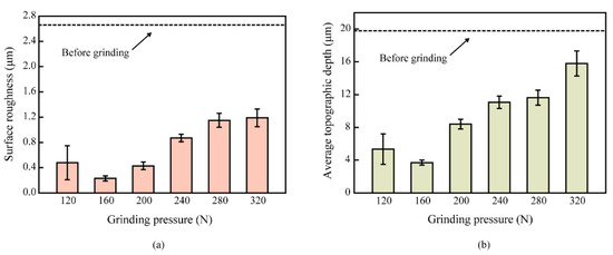
Figure 7.
(a) surface roughness, and (b) topographic depth.
Those results indicate the passive grinding pressure load markedly affects not only the grinding efficiency but also the grinding quality of the rail surface.
3.3. Residual Stress on Rail Surface
The surface of the rail material is under severe plastic strain by abrasive cutting during the grinding of the rail with the grinding wheel. The material change will result in the growth of residual stress on the rail surface [30]. Figure 8 shows the residual stresses on the rail surface before and after passive grinding. The rail surface before grinding mainly appears residual compressive stress of −145 MPa. After grinding, the residual stress of rail grinding surface changes significantly. In addition, due to grinding along the 45° direction, the residual stress can be divided into parallel and perpendicular directions of grinding marks [31]. The influence rules of grinding loads on residual stress along parallel and vertical to grinding direction are different. The residual stress along vertical to grinding direction is always maintained at a low stress; however, the residual stress along parallel to grinding direction continuously augments with the enhancement of grinding pressure load.
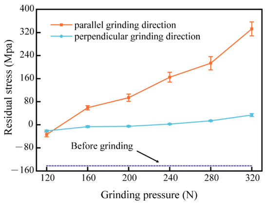
Figure 8.
Residual stress on the rail surface before and after grinding.
It is generally known that the abrasive cutting edge can be regarded as a tool with a large negative front angle. The rail material is stretched during grinding, and the stress exceeds the yield limit of the material causing plastic deformation; in consequence, the grinding heat generates on grinding surface. However, the rail surface temperature will drop rapidly when the abrasive passes through the grinding zone, and the steel surface will shrink, resulting in the emergence of residual tensile stress [32,33]. This phenomenon has become more obvious by the fact that there is no cooling fluid in the dry grinding of the rail during maintenance grinding. With the increase of grinding load, the grinding depth also increases, which leads to the serious deformation in the grinding surface. As a result, the residual stress along direction parallel to grinding direction increases distinctly; additionally, the residual stress perpendicular to the grinding direction also increases slightly due to extrusion.
3.4. Wear Morphologies of Grinding Wheels
Figure 9 shows optical micrographs of the grinding surface of grinding wheels after grinding tests. At low grinding load, there is a small amount of aging resin layer on the surface of the grinding wheel, and the abrasive is not basically worn, as shown in Figure 9a,b. With the increase of grinding load, the aging residual resin layer reduces; concurrently, fine cracks can be observed in some abrasives when the load is over 160 N, as shown in Figure 9c,d. These cracks are the precursor of abrasive self-sharpening. If the cracks continue to increase and expand, it will produce noticeable abrasive self-sharpening, as shown in Figure 9e,f. This characteristic that occurred in grinding wheel surface is a normal phenomenon which is attributed to zirconium corundum keeping its grinding sharpness in grinding process. With the increase of grinding load, the amounts of fine cracks and abrasive self-sharpening increases, and some fissures appear on the interface between resin bond and abrasive, as shown in Figure 9e. While the load further increases to 320 N, not only the number of fissures increases but also some crushed abrasives are observed. Some holes even formed because of abrasives shedding. Excessive fissures and abrasive self-sharpening in a short grinding time will seriously shorten the service life of grinding wheels, accelerate the wear of the grinding wheel and result in the grinding ratio decreasing remarkably as shown in Figure 4. The results suggest that besides the passive grinding pressure affecting the surface quality after rail maintenance, it also directly reduces the durability of grinding wheel; furthermore, it affects the grinding schedule of the rail. Therefore, it is important to choose the suitable grinding pressure load for passive grinding to achieve the best maintenance.
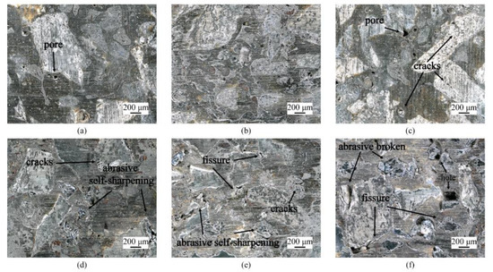
Figure 9.
OM of the grinding wheels: (a) 120 N, (b)160 N, (c) 200 N, (d) 240 N, (e) 280 N, (f) 320 N.
3.5. Grinding Force
Recording the grinding force generated during the grinding process can assist in analyzing the passive grinding. In this work, the three-dimensional mechanical sensor was used to measure the grinding force. The total grinding force along the direction of the grinding marks was directly calculated by LabView software, and the result is shown in Figure 10. Obviously, the grinding force rises with the increase of grinding pressure load. At the same time, the grinding force with the grinding time appears slightly diverse at different grinding pressure load. For example, as the grinding load is 120 N, the grinding force with grinding time is relatively stable; Whereas, when the load is over 280 N, the grinding force fluctuates slightly up and down around a value with the increase of grinding time. At this point, a significant vibration of the grinding wheel during grinding can be observed.
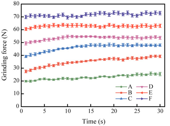
Figure 10.
Grinding force under different grinding loads.
It is known that the grinding force is one of the most important parameters to affect the grinding effectiveness, which depends on the grinding pressure. However, in passive grinding, the grinding pressure is not only the source of the cutting force but also provides torque to the grinding wheel. Accordingly, when the grinding pressure load is low, there is not sufficient grinding force and torque to keep the grinding wheel turning steadily. The weak grinding force results in a lower grinding efficiency that cannot completely remove the surface defects of the rail. Meanwhile, the self-sharpening of grinding wheel may not be adequately carried out. With the increase of grinding load over 160 N, the sufficient grinding force is generated to make the grinding wheel effectively remove the rail defects within the specified time and rotate steadily. Simultaneously, the self-sharpening of grinding wheels may occur gradually during the grinding process, as shown in Figure 9c–e. The surface morphology of the rail changes as the cutting occurs. However, with the further increase of grinding load over 280 N, the excessive grinding load and grinding force may cause grinding wheel damage and rail surface wear during grinding, resulting in slight fluctuations of grinding force with the grinding time.
3.6. Grinding Temperature
In the process of maintaining the rail, it is an important problem that the surface of the rail is burnt because of the high grinding heat and no coolant to cool the surface. Figure 11 shows the temperature change of the contact interface between the grinding wheel and the rail under different grinding pressure loads, in which Figure 11a is measured by thermocouple and Figure 11b is measured by infrared thermometer. The results obtained by the two methods differed significantly. The main reason for the difference is that the measuring point of the thermocouple is the grinding center, while the measuring point of the infrared thermometer is the surface of the rail near the grinding center. Due to the high speed of passive grinding, once the rail surface is removed from the grinding center, the heat source will be lost immediately and part of the heat will be quickly taken away by the air flow and ambient temperature difference. It is worth noting that the higher the grinding pressure load, the faster the temperature rises and the higher the maximum grinding temperature at the end of grinding. According to the relevant research study [34], when the grinding temperature exceeds 470 °C, oxidation and burns may occur on the rail surface. In the test, the temperature exceeded 470 °C only as the grinding load was 320 N (i.e., 485.5 °C), and the maximum grinding temperature at the end of the test did not exceed 400 °C at any other grinding load. The results in Figure 5 can also be confirmed: no yellow or blue oxide film can be observed on the surface of the rail. The results indicate that the passive grinding has higher speed (the passive grinding train is 60~80 km/h) and the grinding time on the rail surface is relatively short (around 15~30 s). Therefore, the rapid heat diffusion will not easily cause the rail surface to burn under proper grinding pressure load.
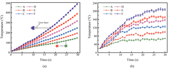
Figure 11.
Temperature curves under different grinding pressure loads, (a) grinding center temperature, (b) rail surface temperature.
3.7. Grinding Debris
The removal mechanism of passive grinding rail can be studied according to morphology and composition of grinding debris. Figure 12 shows the SEM images of debris under different grinding load. There are mainly three types of grinding debris collected after the experiment: serrated debris, spherical melt debris and banded debris. Apparently, the grinding pressure affects the characteristics of the debris. As the grinding load is 120 N, the number of spherical melt debris is relatively small, most of which are banded and lump serrated debris with larger size, as shown in Figure 12a. Nevertheless, when the grinding load increases to 160 N, the size of grinding debris becomes smaller, as shown in Figure 12b. Then, as the grinding load continues to rise, the size of debris gradually increases, while the amount of spherical melt debris also gradually grows. Especially, as the grinding force is greater than 280 N, the banded debris becomes large and continuous, and obvious abrasive chips appear in the debris.
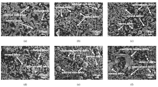
Figure 12.
The SEM of debris, (a) 120 N, (b)160 N, (c) 200 N, (d) 240 N, (e) 280 N, (f) 320 N.
Figure 13 shows the SEM images and EDS analysis of the three main forms of grinding debris. The spherical grinding debris has a very fine irregular dendritic microstructure and its main elements are iron, manganese and oxygen. This suggests that spherical melt debris is oxidized in the air. Furthermore, because of the extremely rapid melting and solidification stages, its internal structure is hollow inside. Compared with spherical melt debris, serrated debris also contains the elements of iron, manganese and oxygen, but the oxygen content is less than spherical melt debris. This indicates that although there is oxidation in serrated debris, the degree of oxidation is lower than that in spherical melt debris. The banded debris has almost no oxidation because no oxygen can be discovered in it.
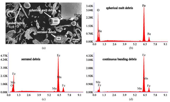
Figure 13.
SEM images and EDS analysis of the grinding debris, (a) SEM of debris, (b) spherical melt debris, (c) serrated debris, (d) continuous banding debris.
Figure 14 shows the XRD spectrum of the grinding debris collected from grinding under grinding load of 240 N. The debris mainly consists of five substances: Fe, Fe2O3, Fe3O4, ZrO2 and Al2O3. The result illustrates that the rail is removed to form debris, and debris is oxidized in the process of passive grinding. Meanwhile, some abrasives fall off from grinding wheel during the grinding process, which results in the phenomenon of self-sharpening.
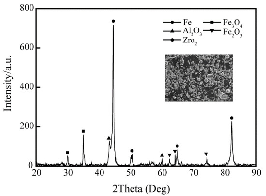
Figure 14.
XRD spectrum of debris under pressure load of 240 N.
4. Discussion
Passive rail grinding is a new rail grinding strategy. Compared with the traditional active grinding method, it has the characteristics of speed and efficiency [12,16], which can effectively make up for the deficiency of active grinding in railway preventive grinding [13,17]. During the process of rail passive grinding, complex material removal and tribological behaviors take place between the grinding wheel and rail. However, it is difficult to detect and analyze passive grinding under the actual working condition, and there is no test equipment available that is specialized in passive grinding. Therefore, a kind of small-scale simulation equipment of rail passive grinding was designed based on the tool grinding machine in this work.
In practical applications, grinding pressure is a key factor in the effectiveness of passive grinding. Under different grinding pressure load conditions, not only the rail surface topographies after passive grinding are significantly diverse but also the service life of the grinding wheel is affected. In order to understand the passive grinding characteristics and develop process specifications for grinding pressure, a series of experiments were performed to study the influence of grinding pressure load on the rail material removal performance and the use of grinding wheels in passive grinding.
According to experimental results, it can be found that the change of grinding pressure has a profound influence on the grinding effect. Concerning the grinding quality, the increase in grinding pressure load will lead to the change of rail surface topography and the increase of surface residual stress. In the experiment, as the grinding pressure load increases from 120 N to 320 N, the rail surface roughness first decreases and then increases, as shown in Figure 7. The first decline occurs because the surface defects are removed by passive grinding, which gives rise to the decrease of roughness and topographic depth. After that, the downward trend converts as the grinding pressure load increases sufficiently to completely remove the defects. The roughness and topographic depth increase with the increase of grinding pressure load. Finally, when the grinding pressure load increases to a certain level, the upward trend will not be prominent. It indicates that the surface roughness of the rail after passive grinding can be controlled within a certain range by adjusting the load, to meet the maintenance requirements of the rail. Moreover, under pressure load exceeding 280 N, the rail surface emerges to wear after grinding, which is harmful to the rail. In addition, the residual stress and plastic deformation on the rail surface increase with the grinding pressure load. These will shorten the service life of the rail because the residual stress and plastic deformation promote the formation and propagation of fatigue cracks [35]. However, there is not enough research to explain how residual stresses interact with grinding wheels or wheels in rolling contact. It is still an open point that is worth investigating. Therefore, after conversion, it is suggested that the actual passive grinding pressure load should be controlled between 1600 N and 2800 N according to the grinding quality.
For maintenance efficiency, under low grinding pressure load, though passive grinding can be carried out, the defects may not be completely removed in the required time due to the low grinding efficiency. For instance, when the grinding load is 120 N, the grinding efficiency of a single test wheel on the rail is only 13.4 mg/s, as shown in Figure 4. After 30 s of passive grinding on the rail sample, the grooves existing on the rail surface are not completely removed, as shown in Figure 5b and Figure 6b. The advantage of passive grinding is high speed and high efficiency, which can complete rail maintenance in a short “skylight time”. A low removal rate will make passive grinding lose its superiority. The most convenient solution to improve grinding efficiency is to increase the grinding pressure load. The results demonstrate a significant increase in grinding efficiency from 13.4 mg/s to 107.5 mg/s with the increase in grinding load from 120 N to 320 N, as shown in Figure 4.
The removal principle of passive grinding can be analyzed by analogy with heavy load fixed force grinding. The relationship between grinding removal rate and grinding pressure load is obtained through the comparative analysis of cutting models and expressed as Equation (1) [26].
In formula (1), the parameter K is related to the grinding force characteristics of passive grinding, while qs is related to the quality of the abrasive particles themselves. The value of qs depends on the chemical composition of the abrasive particles rather than the size or shape. High zirconium content abrasive is commonly used in rail grinding. The high zirconium content of zirconium corundum abrasive has a lower qs value in grinding steel because it has a higher melting point and chemical stability than the alumina abrasive [26]. It can be viewed in the formula that under ideal conditions if the abrasive particles never wear (qs = 0), the rail removal rate is only related to the grinding pressure under a certain speed. The higher the grinding pressure, the higher the grinding removal rate. However, the abrasive must be worn in actual grinding. If qs is set as a constant value, the greater the wear rate of the grinding wheel (Qs), the higher the rail removal rate (Qw). These demonstrate that the increase of passive grinding efficiency is related to the pressure load and related to the grinding wheel wear.
Although more grinding wheel wear can improve grinding efficiency, the service life of grinding wheels plays a non-negligible role in the economics of grinding. The grinding ratio drops off with the increase of grinding pressure load, which shows the durability of grinding wheel decreases as the working pressure load increases. The phenomenon of frequency wheel replacement caused by excessive grinding load is undesirable to see. When observing the surface morphology of grinding wheel after grinding test, there is no obvious wear on the grinding surface under the load below 200 N. However, when the grinding load exceeds 240 N, visible fissures would appear on the grinding surface of the wheel, and the abrasive will break or even fall off to form holes, as shown in Figure 9. If the grinding wheel shows serious abrasion only after 30 s grinding, it is not the normal self-sharpening of the grinding wheel but the damage caused by excessive pressure load. Therefore, it is not appropriate for the grinding pressure load to exceed 2400 N in actual working conditions. This is essential for the application of passive grinding in practice. Frequent replacement of grinding wheels is often caused by excessive grinding pressure load during online grinding, which adds significant economic costs.
So, the influence of the increase of grinding pressure load on the passive grinding is not just a favorable relationship. The enhancement of grinding load will not only increase the grinding efficiency but reduce the service life of grinding wheel and the rail surface quality after grinding. It is inseparably linked to the variation of the grinding force.
In passive grinding, the grinding pressure load is part of the necessary conditions to produce the grinding behavior, and it also has a very profound impact on the grinding force. Mechanical analysis of passive rail grinding is carried out, as shown in Figure 15. The Fn is the grinding pressure load and Ft is the grinding force that follows the rotating direction of the grinding wheel under the action of the deflection Angle (i.e., θ). For a single abrasive particle, its grinding force Ft′ can be decomposed into Fy′ caused by grinding deformation and Fx′ caused by friction, as shown in Equation (2).
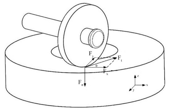
Figure 15.
Mechanical analysis of passive rail grinding.
The total grinding force is obtained by calculating the sum of grinding force of all abrasive per unit width, as shown in Equation (3) [26].
In the formula, the grinding depth can be expressed as Equation (4) [26].
Therefore, at low grinding load, the grinding depth generated by passive grinding is shallow and the grinding force is low, so the grinding wheel and rail wear less. However, when the grinding load is too high, the bond of grinding wheel will crack, and part of the abrasive will break owing to the excessive grinding force. It is also demonstrated by the presence of abrasive debris in the SEM image as shown in Figure 12e,f. This premature self-sharpening behavior is not conducive to continuous rail grinding and it causes the fluctuation of grinding force. In the meantime, the rail surface is worn. The abnormal wear area and residual stress on the rail surface are not beneficial to the extension of rail service life.
The morphology and size of the debris produced by passive grinding under different pressure load can also explain the distinction of grinding process. It is not difficult to find that there is a lot of spherical melt debris under each grinding load. This is because passive grinding is often accompanied by a large number of sparks, and the main components of these sparks are spherical melt debris, as shown in Figure 1c. The number of spherical debris increases with the grinding load, which indicates that more grinding sparks are generated, thus reflecting that the higher grinding force will produce greater rail removal. Whereas the size of the debris is not just increasing with pressure load. In low pressure passive grinding, the cutting depth of the grinding wheel on the rail is shallow as a result of low grinding force, so that the rail is extruded by the abrasive without significant plastic deformation, resulting in large-size serrated lump debris. As the grinding force increases with pressure load, the cutting process returns to normal sliding, plowing and cutting accomplished by the abrasive [36], and the size of the debris decreases. After that, when the grinding load continues to increase, the size of the debris will increase again with the increase of grinding force. However, the large-size debris is not lumped when extruded, but continuous banging debris is. It shows that the change of grinding pressure load will influence the passive grinding process of rail by grinding wheel.
Rail burn caused by grinding heat is one of the common problems in rail maintenance. Assuming that the grinding heat generated by passive grinding does not lose and is uniformly distributed within the grinding area, the maximum resulting heating value (θm) rise can be expressed in terms of Equation (5) [26].
The greater the grinding pressure, the more heat will be produced. In the grinding time of 30 s, the grinding temperature gradually increases with the increase of grinding time. There are two main reasons for the difference in grinding temperature between the grinding center and its vicinity, one is that the grinding debris goes away with the heat, and the other is that the self-sharpening of the grinding wheel also takes some of the heat away. The rapid relative motion causes a large number of spherical melt debris to emit along the grinding direction, forming a sparking bouquet that carries away heat.
Normally, due to the low running speed (3~20 km/h) of the train in the maintenance mode of active grinding, a large amount of heat generated between the rail and the grinding wheel cannot be released. It can easily cause burns to the surface of the rail [34]. The results of passive grinding experiments show that passive grinding is not easy to produce rail burn at suitable grinding pressure loads. There are no obvious blue or yellow oxidation areas on the surface of the rail after grinding, as shown in Figure 5. Under the maximum grinding load, the maximum grinding temperature within 30 s of grinding time was 485.5 °C as shown in Figure 11, which just reached the temperature that could cause rail burns. The temperature under other grinding loads did not reach the burn temperature of the rail. In practice, it has also been proved that passive rail grinding can effectively relieve the burns during rail maintenance compared with active rail grinding with the end face of grinding wheels. It is not only because of the heat taken away by the rail debris and abrasive chips but also because of the high speed and efficiency of passive grinding. Usually, grinding heat often accumulates in the contact area of grinding. High speed grinding is advantageous to the diffusion of heat.
In summary, grinding pressure is one of the key factors affecting passive grinding. The rail maintenance effect should be considered the grinding efficiency and the use of the grinding wheel equally. High grinding efficiency cannot be blindly pursued by improving grinding pressure load. The appropriate grinding pressure is the basic condition for achieving the passive grinding dressing target. Therefore, combined with the guidance of grinding test results to the actual working conditions, the optimal operating effect can be achieved when the passive grinding pressure load of the actual working conditions is between 2000 N and 2400 N. In this grinding pressure load range, it can also take into account the service life of the grinding wheel while ensuring the grinding efficiency and grinding quality. Furthermore, by studying the influence of passive grinding pressure on grinding results, our research team developed the special grinding wheels that match the parameters used in passive grinding according to the characteristics of passive grinding. These wheels have been used in high-speed rail grinding and perform well. The structure and grinding performance of the grinding wheels will be published in a future study.
5. Conclusions
This work investigated a new passive grinding method. Different from the conventional active grinding method, passive grinding has no motor to drive the wheel to rotate. It relies solely on grinding pressure load, wheel deflection angle and relative motion to produce the grinding behavior. As a new technology, this grinding method has the advantages of high speed and efficiency when applied to rail preventive maintenance. However, the current research on rail grinding is all about active grinding and there is no research on the methods of passive grinding. In order to study the passive grinding behavior, a passive grinding simulation machine which can measure the grinding force and temperature was developed, and it proved that the tester can be used for the test of passive grinding. Under the condition of control of grinding speed, grinding time and grinding wheel deflection angle, the passive grinding tests of different grinding pressure loads were carried out on the rail surface, and the grinding results were tested and analyzed. The main conclusions from this work are as follows.
- (1)
- The increase in passive grinding pressure load will improve the grinding efficiency but will reduce the service life of the grinding wheel and increase the residual stress on the rail surface. Too low grinding load cannot completely remove defects on the rail surface, and excessive grinding load will cause rail wear and lead to rail maintenance quality degradation. According to the calculation of the experimental results, the passive grinding effect is best when the grinding load is in the range of 2000~2400 N under actual working conditions.
- (2)
- Through the analysis of grinding force in passive grinding, it is found that the grinding depth will deepen with the increase of grinding pressure load, which will enhance the grinding force. For every 40 N increase in load on a single grinding wheel in the test, the grinding force increases by about 10 N.
- (3)
- The maximum surface temperature of the rail was below 500 °C after the grinding wheel continued to passively grind the rail for 30 s in the test. Due to the characteristics of high speed, passive grinding does not make it easy to burn the rail surface at suitable grinding pressure loads.
- (4)
- The hollow spherical melt debris accounts for the majority of grinding debris and contains a large amount of oxygen, which is the main component of the spark produced by grinding. The distinction in debris morphology and composition reflects the influence of grinding pressure load on the passive grinding process.
Author Contributions
P.-Z.L.: Validation, Methodology, Visualization, Investigation, Data Curation, Writing—original draft. W.-J.Z. and J.P.: Resources, Funding acquisition, Project administration. X.-D.S.: Formal analysis. F.-R.X.: Conceptualization, Supervision, review and editing. All the authors confirm that the manuscript has been read and approved, and the order of authors listed in the manuscript has been approved by all of the authors. All authors have read and agreed to the published version of the manuscript.
Funding
This research was funded by Science and Technology Department of Henan Province, grant number No. 181200212000.
Institutional Review Board Statement
The study did not involve humans or animals.
Informed Consent Statement
Not applicable. The study did not involve humans.
Data Availability Statement
The datasets used or analysed during the current study are available from the corresponding author on reasonable request.
Conflicts of Interest
The authors declare that they have no known competing financial interests or personal relationships that could have appeared to influence the work reported in this paper.
Nomenclature
| OM | optical microscope |
| SEM | scanning electron microscope |
| XRD | X-Ray Diffraction |
| lc | contact arc length |
| αp | depth of cut (grinding depth) |
| d | equivalent diameter of grinding wheel |
| Qw | removal rate of rail |
| Qs | wear of grinding wheel |
| K | removal coefficient |
| qs | sensitivity of abrasive wear of grinding wheel |
| vs | linear velocity of grinding wheel |
| Fn | grinding pressure |
| Ft | grinding force |
| θ | deflection angle of grinding wheel |
| Fp | grinding forces on unit cutting area |
| α | half-angle of the cone at the top of the abrasive grain |
| vw | linear velocity of rail |
| N | the number of abrasive grains involved in grinding per unit width |
| μ | friction coefficient |
| δ | actual contact area between the rail and the abrasive grains |
| average contact pressure between the actual wear surface of the abrasive grains and the rail | |
| b | grinding width |
| E* | equivalent elastic modulus |
| θm | maximum resulting heating value |
| q | energy input per unit area of the grinding area flowing to the grinding target |
| σ | thermal diffusivity |
| thermal conductivity | |
| vw’ | relative movement speed of rail (speed of grinding train) |
References
- Satoh, Y.; Iwafuchi, K. Effect of rail grinding on rolling contact fatigue in railway rail used in conventional line in Japan. Wear 2008, 265, 1342–1348. [Google Scholar] [CrossRef]
- Ishida, M.; Akama, M.; Kashiwaya, K.; Kapoor, A. The current status of theory and practice on rail integrity in Japanese railways—Rolling contact fatigue and corrugations. Fatigue Fract. Eng. Mater. Struct. 2010, 26, 909–919. [Google Scholar] [CrossRef]
- Tyfour, W.R. Predicting the Effect of Grinding Corrugated Rail Surface on the Wear Behavior of Pearlitic Rail Steel. Tribol. Lett. 2008, 29, 229–234. [Google Scholar] [CrossRef]
- Cuervo, P.A.; Santa, J.F.; Toro, A. Correlations between wear mechanisms and rail grinding operations in a commercial railroad. Tribol. Int. 2015, 82, 265–273. [Google Scholar] [CrossRef]
- Singleton, R.; Marshall, M.B.; Lewis, R.; Evans, G. Rail grinding for the 21st century—Taking a lead from the aerospace industry. Proc. Inst. Mech. Eng. Part F J. Rail Rapid Transit 2014, 229, 457–465. [Google Scholar] [CrossRef]
- Magel, E.; Roney, M.; Kalousek, J.; Sroba, P. The blending of theory and practice in modern rail grinding. Fatigue Fract. Eng. Mater. Struct. 2010, 26, 921–929. [Google Scholar] [CrossRef]
- Grassie, S.L. Rolling contact fatigue on the British railway system: Treatment. Wear 2005, 258, 1310–1318. [Google Scholar] [CrossRef]
- Dlest, K.V. Preventive grinding to combat rolling contact fatigue. Railw. Gaz. Int. 2011, 167, 32–34. [Google Scholar]
- Stanford, J. Preventive-Gradual Rail Grinding Pays Dividends. Int. Railw. J. Rapid Transit Rev. 2000, 40, 25–26. [Google Scholar]
- Li, H.; Tang, S. Experimental Study on the GMC96B Rail Grinding Train. Railw. Qual. Control 2011, 12, 38–44. (In Chinese) [Google Scholar]
- Zhou, K.; Ding, H.; Wang, R.; Yang, J.; Wang, W. Experimental investigation on material removal mechanism during rail grinding at different forward speeds. Tribol. Int. 2019, 143, 106040. [Google Scholar] [CrossRef]
- Von Diest, K.; Meyer, R. German turnouts get the high-speed grinding treatment. Int. Railw. J. 2016, 56, 36–38. [Google Scholar]
- Von Diest, K.; Beier, M. High-speed grinding is beneficial for noise abatement too. Rail Technol. Rev. 2012, 52, 40–44. [Google Scholar]
- Neto, A.C.; Diest, K.V.; Ferrarotti, G.; Kik, W. Wear Analysis of the High-Speed-Grinding Vehicle HSG-2: Validation, Simulation and Comparison with Measurements. In Dynamics of Vehicles on Roads and Tracks, Proceedings of the 25th International Symposium on Dynamics of Vehicles on Roads and Tracks (IAVSD 2017), Rockhampton, Australia, 14–18 August 2017; CRC Press: Boca Raton, FL, USA, 2018. [Google Scholar]
- Von Diest, K.; Puschel, A. High speed grinding—Railway noise reduction through regular rail grinding without traffic interruptions. In Proceedings of the INTER-NOISE and NOISE-CON Congress and Conference Proceedings, Innsbruck, Austria, 15 September 2013. [Google Scholar]
- Diest, K.; Beier, M. High Speed Grinding: Evolution einer etablierten Technik. Senbahntechnische Rundsch. 2015, 64, 54–57. [Google Scholar]
- Diest, K.V. High Speed Grinding: Schienenschleifen 2.0. Der Eisenb. 2010, 61, 30–32,34. [Google Scholar]
- Uhlmann, E.; Lypovka, P.; Hochschild, L.; SchrÖEr, N. Influence of rail grinding process parameters on rail surface roughness and surface layer hardness. Wear 2016, 287–293. [Google Scholar] [CrossRef]
- Zhang, W.; Zhang, P.; Zhang, J.; Fan, X.; Zhu, M. Probing the effect of abrasive grit size on rail grinding behaviors. J. Manuf. Process. 2020, 53, 388–395. [Google Scholar] [CrossRef]
- Wang, R.X.; Zhou, K.; Yang, J.Y.; Ding, H.H.; Wang, W.J.; Guo, J.; Liu, Q.Y. Effects of abrasive material and hardness of grinding wheel on rail grinding behaviors. Wear 2020, 454–455, 203332. [Google Scholar] [CrossRef]
- Wu, H.; Xiao, B.; Xiao, H.; Zhang, Y.; Dou, L. Study on wear characteristics of brazed diamond sheet for rail’s composite grinding wheel under different pressures. Wear 2019, 424–425, 183–192. [Google Scholar] [CrossRef]
- Pereverzev, P.P.; Pimenov, D.Y. A grinding force model allowing for dulling of abrasive wheel cutting grains in plunge cylindrical grinding. J. Frict. Wear 2016, 37, 60–65. [Google Scholar] [CrossRef]
- Zhang, S.; Zhou, K.; Ding, H.; Guo, J.; Liu, Q.; Wang, W. Effects of Grinding Passes and Direction on Material Removal Behaviours in the Rail Grinding Process. Materials 2018, 11, 2293. [Google Scholar] [CrossRef]
- Zhe, H.; Li, J.; Liu, Y.; Meng, N.; Fan, W. Investigating the effects of contact pressure on rail material abrasive belt grinding performance. Int. J. Adv. Manuf. Technol. 2017, 93, 779–786. [Google Scholar] [CrossRef]
- Lu, Z.W. Selection of rail materials for high-speed railway. China Railw. 2004, 10, 35–38. (In Chinese) [Google Scholar]
- Malkin, S. Grinding technology: Theory and Applications of Machining with Abrasives; Society of Manufacturing Engineers: Southfield, MI, USA, 1989. [Google Scholar] [CrossRef]
- Meng, N.; Jianyong, L.; Haikuo, S.; Shaodan, Z. Study on Reducing the Grinding Pressure Fluctuation on Rail Grinding Train. Adv. Inf. Sci. Serv. Sci. 2013, 5, 932–939. [Google Scholar]
- Termite, L.; Grüner, L.; Diest, K.V. Grindstone Assembly with Minimal Resulting Momentum and Power. EP2390415A1, 29 April 2015. [Google Scholar]
- Zhang, Y.; Li, C.; Ji, H.; Yang, X.; Yang, M.; Jia, D.; Zhang, X.; Li, R.; Wang, J. Analysis of grinding mechanics and improved predictive force model based on material-removal and plastic-stacking mechanisms. Int. J. Mach. Tools Manuf. 2017, 122, 81–97. [Google Scholar] [CrossRef]
- Ding, Z.; Li, B.; Liang, S.Y. Phase transformation and residual stress of Maraging C250 steel during grinding. Mater. Lett. 2015, 154, 37–39. [Google Scholar] [CrossRef]
- Cao, Y.J.; Sun, J.Q.; Ma, F.; Chen, Y.Y.; Cheng, X.Z.; Gao, X.; Xie, K. Effect of the microstructure and residual stress on tribological behavior of induction hardened GCr15 steel. Tribol. Int. 2017, 115, 108–115. [Google Scholar] [CrossRef]
- Chen, X.; Rowe, W.B.; Mccormack, D.F. Analysis of the transitional temperature for tensile residual stress in grinding. J. Mater. Process. Technol. 2000, 107, 216–221. [Google Scholar] [CrossRef]
- Balart, M.J.; Bouzina, A.; Edwards, L.; Fitzpatrick, M.E. The onset of tensile residual stresses in grinding of hardened steels. Mater. Sci. Eng. A Struct. Mater. 2004, 367, 132–142. [Google Scholar] [CrossRef]
- Lin, B.; Zhou, K.; Guo, J.; Liu, Q.Y.; Wang, W.J. Influence of grinding parameters on surface temperature and burn behaviors of grinding rail. Tribol. Int. 2018, 122, 151–162. [Google Scholar] [CrossRef]
- ÖSterle, W.; Li, P.X.; Nolze, G. Influence of surface finishing on residual stress depth profiles of a coarse-grained nickel-base superalloy. Mater. Sci. Eng. A 1999, 262, 308–311. [Google Scholar] [CrossRef]
- Zhou, K.; Ding, H.H.; Wang, W.J.; Wang, R.X.; Guo, J.; Liu, Q.Y. Influence of grinding pressure on removal behaviours of rail material. Tribol. Int. 2019, 134, 417–426. [Google Scholar] [CrossRef]


Publisher’s Note: MDPI stays neutral with regard to jurisdictional claims in published maps and institutional affiliations. |
© 2021 by the authors. Licensee MDPI, Basel, Switzerland. This article is an open access article distributed under the terms and conditions of the Creative Commons Attribution (CC BY) license (https://creativecommons.org/licenses/by/4.0/).