Article

Contrastive Analysis on the Ventilation Performance of a Combined Solar Chimney

1
College of Urban Construction, Nanjing Tech University, Nanjing 210009, China
2
Anhui Province Key Laboratory of Human Safety, Hefei Institute for Public Safety Research, Tsinghua University, Hefei 230602, China
*
Author to whom correspondence should be addressed.
Appl. Sci. 2022, 12(1), 156; https://doi.org/10.3390/app12010156
Submission received: 30 September 2021 / Revised: 23 November 2021 / Accepted: 26 November 2021 / Published: 24 December 2021
(This article belongs to the Special Issue Recent Progress in Solar Thermal Technologies and Applications)

Abstract

:
A combined solar chimney is proposed in this paper that integrates an inclined-roof solar chimney with a traditional Trombe wall. The ventilation performance of the combined solar chimney is analyzed numerically and then compared with the Trombe wall and the inclined-roof solar chimney. The feasibility of different operation modes and the ventilation effect under different environment conditions are also discussed. The results show that when the ambient temperature ranges from 298 to 303 K in the summer, a natural ventilation mode is appropriate. Otherwise, an anti-overheating mode is recommended. When the ambient temperature is lower than 273 K in the winter, a space heating mode has a better heating effect. A preheating mode can be employed to improve the indoor air quality when the ambient temperature is higher than 278 K. The simulation results indicates that the ventilation effect of the combined solar chimney is better than that of the Trombe wall and the inclined-roof solar chimney, and the problem of overheating can be avoided. The study provides guidance for the optimal operation of a combined solar chimney.

1. Introduction

With rapid economic growth and continuous urbanization, the world’s energy consumption is increasing rapidly. The CO2 emissions in 2019 in China—the world’s largest energy consumer—were approximately 9.825 billion tons, accounting for nearly one third of the world’s total emissions [1]. Building energy consumption accounts for 30% of the total energy consumption, mainly for building heating, ventilation, and air-conditioning [2,3,4,5]. Therefore, measures of using renewable energy to reduce the energy consumption and carbon emissions of buildings have been promoted to realize the goal of an emissions peak by 2030 and to be carbon neutral by 2060.
At present, solar energy is one of the most commonly used renewable energy sources. A solar chimney is an efficient technology combining chimney technology with solar thermal utilization technology to enhance the natural ventilation of a building [6]. The solar chimney has a simple structure and is mainly composed of a glass cover, an inlet and outlet, and a storage wall. According to the combination of a solar chimney and a building, there are three main structural types: an inclined-roof solar chimney, a vertical solar chimney, and a Trombe wall solar chimney [7,8,9]. A vertical solar chimney and an inclined-roof solar chimney have a better ventilation effect in the summer but they are not suitable for winter heating. A Trombe wall can be used for both summer ventilation and winter heating. However, when it is used in the summer, the ventilation flow rate is usually restricted and overheating is inevitable [10,11,12,13].
The ventilation performance of a solar chimney is mainly affected by structural factors and environmental conditions, for example [14]. Studies indicate that the daily average air-conditioning energy consumption of houses with solar chimneys can reduce by approximately 10% to 20% compared with ordinary rooms. If the operation mode is suitable, it can save 30% of operating costs [15]. Hosien [16] found that when the air gap of a vertical solar chimney is 0.1–0.5 m, the corresponding mass flow rate is 0.04–0.18 kg/s. The mass flow rate increase can reach up to 4.5 kg/s∙m, which is 900 times higher than that of a chimney height in the range of 2–8 m. Bassiouny [17] compared the indoor air distribution of an inclined solar chimney at different inclination angles. It was found that when the inclination angle was below 30°, the flow resistance at the inlet of the chimney was higher due to a worse penetration depth and a streamlined distribution of the air flow. In addition, it was pointed out that when the latitude was 28.4° N, the optimal inclination angle ranged from 45° to 70°. Harris [18] conducted a comparative simulation analysis of a vertical solar chimney and an inclined solar chimney at a latitude of 52° in the Edinburgh area of Scotland. The simulation results showed that the air flow rate was the largest when the inclination angle was 67.5°. Compared with a vertical solar chimney, the air flow rate of an inclined solar chimney increased by 11%. Jing [19] conducted an experiment on an inclined solar chimney with a thickness-to-height ratio between 0.2 and 0.6. The results showed that the air flow rate could be maximized when the height was 2 m and the air gap was 1 m. The optimum thickness-to-height ratio was approximately 0.5.
In order to improve the performance of a solar chimney, structurally improved systems have been proposed and studied by researchers. Du [20] studied the ventilation performance of a combined solar chimney (CSC) with a two-story house. It indicated that the optimal length-to-width ratio was 12:1 and the ratio of the length of the vertical part to the inclined part was 1.175. Aboulnaga [21] compared a combined solar chimney with an inclined solar chimney. It was indicated that when the solar radiation was 850 W/m2, the air flow rate of the inclined solar chimney and the combined solar chimney were 0.81 m3/s and 2.3 m3/s, respectively. The results showed that the combined solar chimney had a better ventilation effect than that of an inclined solar chimney. Zhang [22] established a mathematical model of a combined solar chimney by an energy balance method. It was found that the ventilation performance was improved with the increase of the width and height of the chimney but an excessive air gap reduced the air flow rate. The optimal air gap was 0.1 m and the optimum inclination angle could be controlled between 30° and 60° depending on the situation.
A combined solar chimney (CSC) can be utilized for both summer ventilation and winter heating. However, the influence of structural parameters on the ventilation performance of a combined solar chimney is different from that of a single-structured solar chimney. At present, research has mostly focused on the thermal and ventilation properties of a solar chimney as well as the influences of structural and environmental factors on the ventilation effect, especially in a single-structured solar chimney. Few studies have focused on the operation modes and their applicability in different environmental conditions [23].
In this study, numerical models of a combined solar chimney (CSC) were established to research the natural ventilation and space heating effect of four different operation modes; that is, natural ventilation modes in summer, an anti-overheating mode in summer, a space heating mode in winter, and a preheating mode in winter. In order to verify the improvement of the ventilation performance, an inclined-roof solar chimney (IRSC) and a Trombe wall (TW) system were also discussed for comparison.
The novelty of this paper lies in the comparative analysis on the ventilation performance of three different structural solar chimneys under particular operation modes that focuses on the ventilation effect and overheating prevention in the summer. The feasibility and applicability of different operating modes under different environment conditions are discussed as an emphasis. The study is significant for promoting the application of a combined solar chimney in practical engineering, providing guidance for the optimal operation of a solar chimney.

2. Materials and Methods

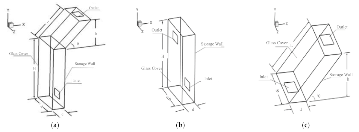
2.1. Physical Models

The schematic of the combined solar chimney (CSC) is shown in Figure 1. The structure was composed of a Trombe wall and an inclined-roof solar chimney, which consisted of an external glass cover and an internal storage wall both in the vertical and inclined part. An air channel was formed between the external glass cover and the internal storage wall. There were four operation modes for the combined solar chimney: a natural ventilation mode for the summer, an anti-overheating mode for the summer, a space heating mode for the winter, and a preheating mode for the winter. The changing of the operation modes could be realized by the switching of the air vents. The natural ventilation mode in the summer (S1) was to open the indoor air outlet, the roof air outlet, and the north air inlet; all other vents were closed, as shown in Figure 1. The anti-overheating mode in the summer (S2) was to open the outdoor air inlet and the roof air outlet; all other vents were closed. The baffle in the above both modes was open. The space heating mode in the winter (W1) was to open the indoor air inlet and the indoor air outlet; all other vents were closed. The preheating mode in the winter (W2) was to open the outdoor air inlet and indoor air inlet; all other vents were closed. The baffle in the above both modes was closed.
In order to simplify the expression, the CSC summer operation mode 1 (natural ventilation mode) and summer operation mode 2 (anti-overheating mode) were referred to as S1CSC and S2CSC, respectively. By this analogy, the operation modes of the Trombe wall in the summer and winter were written as S1TW, S2TW, W1TW, and W2TW for short. There was only a natural ventilation mode for the inclined-roof solar chimney (IRSC) so only the performance in the summer was considered. For the CSC, the top outlet of the inclined part was closed in the winter and its operations were the same as those of the Trombe wall. Therefore, only the performance of the space heating mode and the preheating mode of the Trombe wall in winter conditions were analyzed in this paper.
The physical model of the CSC in different modes as well as the contrastive structures of the TW and IRSC are presented in Figure 2. The geometric parameters of the chimney were determined according to the real size of a rural house in China (with a floor height of over 3.0 m). The dimensions of the different models are listed in Table 1.

2.2. Mathematical Description

The heat transfer process inside a combined solar chimney is a complex dynamic process involving heat convection and radiation. To simplify the theoretical analysis and numerical calculations, assumptions were made as follows:
  • The air inside the chimney was an incompressible Newtonian fluid;
  • The heat transfer was in a steady-state [16]. Both the solar irradiation and the outdoor ambient temperature were constant;
  • All relevant physical properties of the chimney material were independent of the temperature [20];
  • Air penetration was ignored. Heat storage on the storage wall was also ignored to simplify the heat transfer process;
  • This simulation only considered the ventilation performance of a solar chimney under hot-pressing [18].
Three-dimensional steady-state turbulence control equations [24,25]:
Continuity equation:
v i x i   =   0 .
Momentum equation:
v i v j x j   =   1 ρ P x i   +   x j υ   +   υ t v i x j     g i β T     T .
Energy equations:
v j T x j   =   x j Γ T x j
Γ   =   υ Pr   +   υ t σ t .
Turbulent kinetic energy:
k v i x i   =   1 ρ x j υ   +   υ t σ k k x j     ε + G k .
Dissipation rates:
ε v i x i   =   1 ρ x j υ   +   υ t σ ε ε x j   +   ε k c 1 G k     c 2 ε
G k   =   υ t ρ u i x j u i x j   +   u j x i
where vi is the average velocity component in the xi direction, m/s; xi is the coordinate; ρ refers to the air density, kg/m3; P is the pressure, Pa; υt and υ are the turbulent viscous coefficient and laminar viscous coefficient, respectively; gi is the gravitational acceleration in the i direction, m/s2; β is the air thermal expansion coefficient, L/K; T and T are the average temperature and reference point temperature, respectively, K; Γ is the generalized diffusion coefficient; k is the turbulent kinetic energy; ε refers to the dissipation of kinetic energy; Gk refers to the generation of turbulence kinetic energy; Pr is the Prandtl number; and σk, σε, σt, c1, and c2 are empirical values of 1.0, 1.2, 0.9, 1.44, and 1.9, respectively [26,27].
The flowing fluid in the model was air, conforming to the Boussinesq hypothesis [28]. The physical parameter of the main materials and air are listed in Table 2 and Table 3.

2.3. Boundary Conditions

The simulation used the realizable k-ε model and the enhanced wall function method. The finite volume method was used to solve the above governing equations. The SIMPLE algorithm was used to calculate the coupling between the velocity and pressure. The discrete format of the convection term adopted the second-order upwind style. The radiation model used the DO (discrete ordinates) radiation model [29], in which the incident angle of the solar radiation was calculated according to the solar calculator. The solar irradiation was 800 W/m2. The outdoor ambient temperature was 300 K and the operating pressure was 101,325 Pa. The air inlet and outlet were set as the pressure inlet and pressure outlet, respectively. The air temperature at the inlet can be seen in Table 4 and Table 5, according to the seasonal average temperature of Nanjing.

3. Validation

3.1. Mesh Independence Verification

The accuracy of the simulation results and the calculation time depended on the division of the model mesh in the CFD simulation. In this paper, the structured mesh in the ICEM (Integrated Computer Engineering and Manufacturing code) was used for the chimney model and the natural ventilation mode was selected for the verification. The specific structural dimensions and parameter settings of the model are shown in the aforementioned tables. The results showed that the optimal mesh numbers of the IRSC, S1TW, and S1CSC were 158276, 213948, and 357440, respectively. The minimum mesh size was 0.02 m × 0.015 m × 0.025 m and the maximum was 0.04 m × 0.015 m × 0.025 m. More than 95% of the meshes had a mesh quality of 1, indicating that the mesh quality was good and could be used for the simulation.

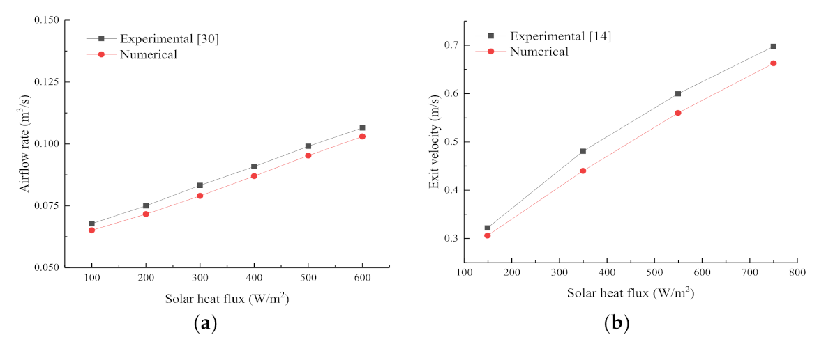
3.2. Validation of the Simulation Method

The structure of a combined solar chimney can be considered to be the composition of a Trombe wall and an inclined-roof solar chimney. Therefore, it is feasible to validate the reliability of the two simple structures of a Trombe wall and an inclined-roof solar chimney. In this paper, the experimental results of the natural ventilation of the Trombe wall and the inclined solar chimney in [14,30] were selected for the simulation verification of the numerical simulation method and model. The same sized models as mentioned in these references were established and the simulation method described in this paper was used for the simulation comparison and verification. The comparison of the numerical simulation results and the experimental results is shown in Figure 3. The relative error was calculated as follows:
E   =   X exp , i     X sim , i X exp , i   ×   100 %
where E is the relative error, Xexp,i is the experimental value, and Xsim,i is the simulation value.
As the wind pressure and other factors were not considered in the simulation, there was a certain relative error between the simulation value and the experimental value. However, it can be seen from Figure 3 that the simulation results were basically consistent with the experimental results and the relative error between the two was less than 7%. The numerical simulation results showed that the flow rate of the solar chimney increased with the increase in the heat flux, which was consistent with the change trend in the experiment. The comparison of the simulation and experimental results showed that the numerical simulation method and models used in this paper had a certain validity and reliability and could be used for subsequent research.

4. Results and Discussion

The same sections of the Y-axis of a section in the solar chimney were selected for a comparative analysis. Due to the difference of the coordinate system, the relative positions for the IRSC were Y = 0.1 m, Y = 0.5 m, and Y = 1 m, respectively. The relative positions for the TW were Y = 0.3 m, Y = 1.25 m, and Y = 2.5 m, respectively. There were five sections of the Y-axis for the CSC; Y = 0.3 m, Y = 1.25 m, Y = 2.5 m, Y = 3 m, and Y = 3.5 m, respectively. The section at Z = 0.75 m was conducted to compare the temperature distribution.

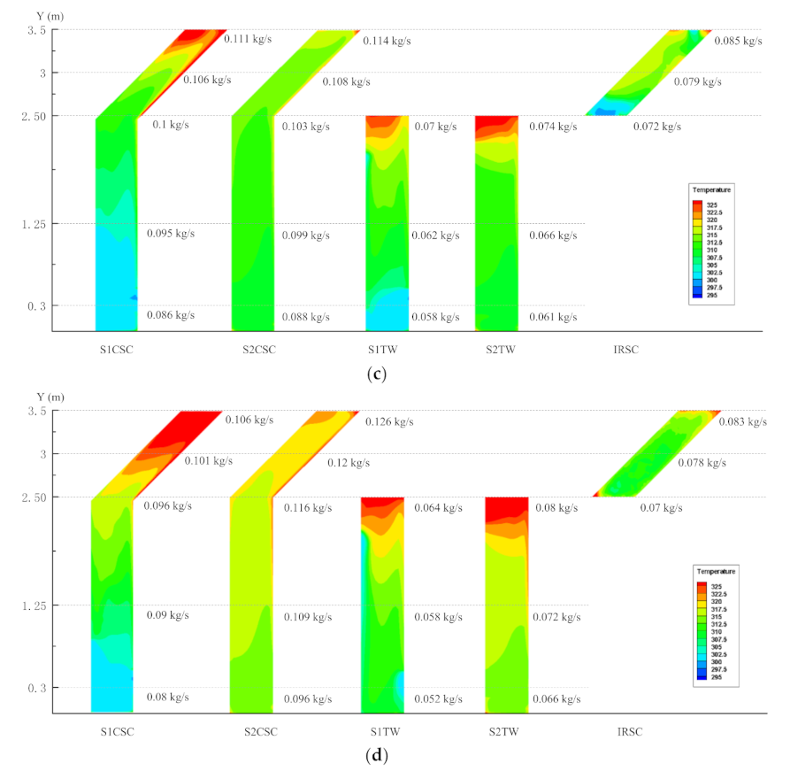
4.1. Temperature Distributions

The temperature distributions of the three structural solar chimneys are shown in Figure 4. For the combined solar chimney in the natural ventilation mode (S1CSC), the temperature distribution of the air in the hot channel was lower and uniform at a given air temperature of 298 K. At this time, the inlet temperature of S1CSC was 300 K and the air temperature in the hot channel was lower than that of S2CSC. When the ambient temperature was 303 K, the temperature close to the inclined storage wall began to rise. The temperature distribution was also uniform with a modicum of an increase both for S1CSC and S2CSC. However, when the ambient temperature was 308 K, the near-wall temperature at the inclined part of S1CSC increased significantly, which was much higher than that of S2CSC. The temperature at the outlet could reach up to 320.4 K. The temperature in the air channel was relatively evenly distributed for S2CSC with little difference from the ambient temperature. There was obvious overheating in the air channel when the ambient air temperature was 313 K. As the inlet temperature of S1CSC was constant and lower than that of S2CSC (equal to the ambient temperature), the air temperature of the hot channel was relatively low when the ambient temperature was 308 K or 313 K. However, the cooling load of the room increased if operated in S1CSC.
Figure 5 shows the changing of the average air temperature in the channel and the temperature of the internal walls with the outdoor ambient temperature. It could be concluded that the temperature of the CSC was lower whereas that of the Trombe wall and the IRSC was relatively higher in the same ambient temperature condition. Owing to the structure composition, the hot air of the CSC was mainly located in the inclined part. It had little influence on the internal wall temperature and the indoor temperature and the problem of overheating could be alleviated to an extent. In contrast, the temperature near the wall of the Trombe wall and the inclined-roof solar chimney was higher, which had an influence on the indoor thermal environment. In addition, the overheating phenomenon was more obvious at a higher ambient temperature.
As shown in Figure 5, the average air temperature in the channel and the storage wall of S1CSC were at the lowest values of 300.8 K and 304.6 K when the ambient temperature was 298 K. These values were 316.2 K and 320.4 K, respectively, for S2CSC when the ambient temperature was 313 K. By comparing the temperature distribution of different structures, it could be indicated that the average air temperature in the channel and the internal wall temperature of S1TW and S2TW were always higher than those of S1CSC, S2CSC, and the IRSC. The Trombe wall structure was more likely to cause indoor overheating in the summer whereas the combined solar chimney structure had the lowest temperature in the air channel and storage wall, which could effectively alleviate overheating in the summer.

4.2. Ventilation Performance

The variation of the ventilation mass flow rate with sections of the Y-axis for different structures is demonstrated in Figure 4. When the ambient temperature was 298 K and 303 K, the mass flow rate of S1CSC was the maximum and that of S2TW was the minimum. The mass flow rate was the maximum for S2CSC and the minimum for S1TW when the ambient temperature varied from 308 K to 313 K. It increased from 0.096 kg/s to 0.128 kg/s for S1CSC with a growth rate of 33.3% at an ambient temperature of 298 K. With the variation of the ambient temperature from 298 K to 313 K, the mass flow rate of S1CSC with sections of the Y-axis increased by 33.3%, 31.2%, 29.4%, and 28.6%, respectively. The growth rate of the S2CSC mass flow rate with sections of the Y-axis were 27.8%, 29.4%, 31.7%, and 32.3%, respectively. The mass flow rate of S1CSC decreased with an increase in the growth rate, which was the reverse for S2CSC. The results illustrated that the ventilation performance of S2CSC gradually improved with the increase in the ambient temperature compared with that of S1CSC. The mass flow rate of the IRSC had no significant changes with the increase in the ambient temperature and ranged from 0.7 to 0.8 kg/s. With the changing of the ambient temperature from 298 K to 313 K, the average mass flow rate of S1CSC decreased from 0.112 kg/s to 0.095 kg/s with a reduction rate of 15.2%. Similarly, the variations of the mass flow rates for S2CSC, S1TW, and S2TW were 0.089~0.113 kg/s, 0.076~0.058 kg/s, and 0.057~0.073 kg/s, respectively. Consequently, the mass flow rate of S1CSC and S1TW decreased gradually whereas that of S2CSC and S2TW increased with the increase in ambient temperature.
In brief, when the ambient temperature was 298 K or 303 K, the average air temperature and the internal wall temperature of S1CSC were the lowest and the mass flow rate was the maximum. In this situation, the natural ventilation mode of the combined solar chimney (S1CSC) in the summer was more suitable without overheating. However, when the ambient temperature reached 308 K or above, the average air temperature in the channel and the internal wall temperature began to rise and the mass flow rate decreased gradually. In this case, the anti-overheating mode (S2CSC) was more suitable. The selection of a suitable operation mode can effectively solve the indoor overheating problem in the summer.

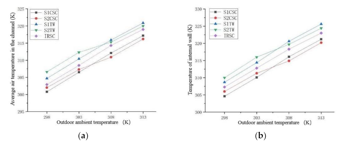
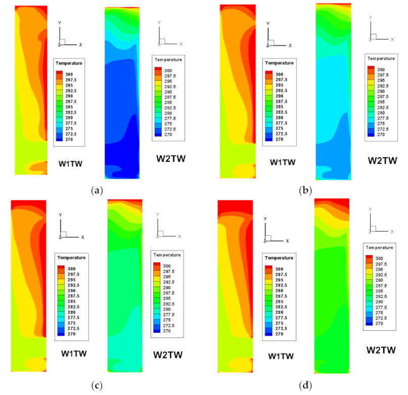
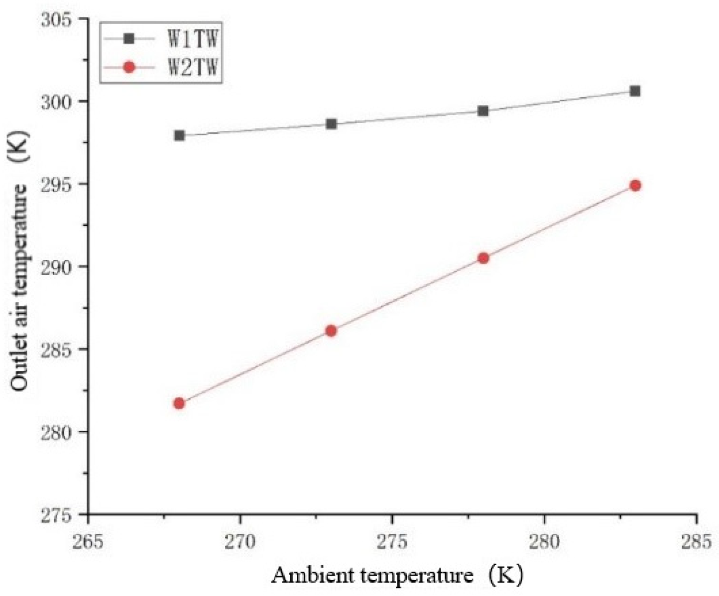
4.3. Thermal Performance in Winter Conditions

The temperature distributions in the hot channel of W1TW and W2TW are presented in Figure 6. The right boundary is the wall and the left boundary is the glass in each heat map. The temperature in the hot channel increased obviously along with an increase in the sections of the Y-axis, which had similar regulations to the summer conditions. The temperature difference along the thickness direction was approximately 8.6 K. The results demonstrated that the temperature in the hot channel was much higher in WITW than in W2TW. However, the temperature difference between the different modes declined with an increase in the ambient temperature.
The outlet air temperature increased with an increase in the ambient temperature for both W1TW and W2TW, as plotted in Figure 7. As the inlet temperature was constant with a value of 291 K, the outlet temperature of W1TW was definite and the temperature rose approximately 8 K. Comparatively, the inlet temperature of W2TW was the same as the ambient temperature and the temperature difference between the outlet and inlet was 11 K. When the ambient temperature was 268 K and 273 K, the outlet temperatures of W1TW were 297.9 K and 198.6 K, respectively, which were much higher than that of W2TW. Therefore, the space heating effect was prominent and applicable in this condition. With an increase in the ambient temperature, the outlet temperature of W2TW raised and the temperature difference between the different modes ranged from 6–9 °C. In this case, the heating effect was approximately identical and W2TW was recommended to preheat fresh air to indoors.

5. Conclusions

The natural ventilation and space heating performance of a combined solar chimney was studied comparatively in this paper. A combined solar chimney has a fine ventilation and space heating effect, which can be utilized in hot summer and cold winter areas. The key findings of the study are summarized below:
  • The ventilation effect of a combined solar chimney was better than that of a Trombe wall and an inclined-roof solar chimney in the summer. The benefit from the structure and the reasonability of the operation mode suggested that the problem of overheating was negligible for a combined solar chimney.
  • In the summer, the natural ventilation mode of a combined solar chimney (S1CSC) was appropriate when the ambient temperature ranged from 298 K to 303 K; the anti-overheating mode was feasible when the ambient temperature was higher than 308 K.
  • When the ambient temperature was lower than 273 K, the operation mode of space heating in winter (W1TW) was suitable with a better heating effect. A preheating mode could be employed to improve the indoor air quality when the ambient temperature was higher than 278 K.

Author Contributions

Conceptualization, H.L. and B.Y.; methodology, H.L., B.Y., Y.W. and Y.Z.; validation, H.L. and B.Y.; formal analysis, P.L., M.Z. and Q.T.; investigation, P.L., M.Z. and Q.T.; data curation, P.L. and Q.T.; writing—original draft preparation, P.L. and Q.T.; writing—review and editing, H.L. and Y.W. All authors have read and agreed to the published version of the manuscript.

Funding

This research was funded by grants from the National Natural Science Foundation of China (No. 51908527), the Natural Science Foundation of the Higher Education Institutions of Jiangsu Province, China (No. 18KJB560009) and The Key Research and Development Projects of Anhui Province, Grant/Award (No. 201904a07020029).

Institutional Review Board Statement

Not applicable.

Informed Consent Statement

Not applicable.

Data Availability Statement

No new data were created or analyzed in this study. Data sharing is not applicable to this article.

Conflicts of Interest

The authors declare no conflict of interest.

References

  1. bp Statistical Review of World Energy 2020: A Pivotal Moment. Available online: https://www.bp.com/en/global/corporate/news-and-insights/press-releases/bp-statistical-review-of-world-energy-2020-published.html (accessed on 23 November 2021).
  2. Li, H.; Yu, Y.; Niu, F.; Shafik, M.; Chen, B. Performance of a coupled cooling system with earth-to-air heat exchanger and solar chimney. Renew. Energy 2014, 62, 468–477. [Google Scholar] [CrossRef]
  3. Perez-Lombard, L.; Ortiz, J.; Pout, C. A review on buildings energy consumption information. Energy Build. 2008, 40, 394–398. [Google Scholar] [CrossRef]
  4. Cheng, X.; Shi, L.; Dai, P.; Zhang, G.; Yang, H.; Li, J. Study on optimizing design of solar chimney for natural ventilation and smoke exhaustion. Energy Build. 2018, 170, 145–156. [Google Scholar] [CrossRef]
  5. Omrany, H.; Ghaffarianhoseini, A.; Ghaffarianhoseini, A.; Raahemifar, K.; Tookey, J. Application of passive wall systems for improving the energy efficiency in buildings: A comprehensive review. Renew. Sustain. Energy Rev. 2016, 62, 1252–1269. [Google Scholar] [CrossRef]
  6. Kasaeian, A.B.; Molana, S.; Rahmani, K.; Wen, D. A review on solar chimney systems. Renew. Sustain. Energy Rev. 2017, 67, 954–987. [Google Scholar] [CrossRef]
  7. Zhai, X.Q.; Song, Z.P.; Wang, R.Z. A review for the applications of solar chimneys in buildings. Renew. Sustain. Energy Rev. 2011, 15, 3757–3767. [Google Scholar] [CrossRef]
  8. Su, Y.; Liu, Z. Research Status on Solar Chimney for Natural Ventilation Enhancement. Sci. Technol. Rev. 2011, 29, 67–72. [Google Scholar]
  9. Monghasemi, N.; Vadiee, A. A review of solar chimney integrated systems for space heating and cooling application. Renew. Sustain. Energy Rev. 2018, 81, 2714–2730. [Google Scholar] [CrossRef]
  10. Wan, W.Q.; Xuan, Y.M. Research Status and Theoretical Analysis on Tilt Solar Chimney. Contam. Control. Air Cond. Technol. 2014, 4, 31–33. [Google Scholar]
  11. Gupta, N.; Tiwari, G.N. Review of passive heating/cooling systems of buildings. Energy Sci. Eng. 2016, 4, 305–333. [Google Scholar] [CrossRef] [Green Version]
  12. Hu, Z.; He, W.; Ji, J.; Zhang, S. A review on the application of Trombe wall system in buildings. Renew. Sustain. Energy Rev. 2017, 70, 976–987. [Google Scholar] [CrossRef]
  13. Chan, H.-Y.; Riffat, S.B.; Zhu, J. Review of passive solar heating and cooling technologies. Renew. Sustain. Energy Rev. 2010, 14, 781–789. [Google Scholar] [CrossRef]
  14. Imran, A.A.; Jalil, J.M.; Ahmed, S.T. Induced flow for ventilation and cooling by a solar chimney. Renew. Energy 2015, 78, 236–244. [Google Scholar] [CrossRef]
  15. Khedari, J.; Rachapradit, N.; Hirunlabh, J. Field study of performance of solar chimney with air-conditioned building. Energy 2003, 28, 1099–1114. [Google Scholar] [CrossRef]
  16. Hosien, M.A.; Selim, S.M. Effects of the geometrical and operational parameters and alternative outer cover materials on the performance of solar chimney used for natural ventilation. Energy Build. 2017, 138, 355–367. [Google Scholar] [CrossRef]
  17. Bassiouny, R.; Koura, N.S.A. An analytical and numerical study of solar chimney use for room natural ventilation. Energy Build. 2008, 40, 865–873. [Google Scholar] [CrossRef]
  18. Harris, D.J.; Helwig, N. Solar chimney and building ventilation. Appl. Energy 2007, 84, 135–146. [Google Scholar] [CrossRef]
  19. Jing, H.; Chen, Z.; Li, A. Experimental study of the prediction of the ventilation flow rate through solar chimney with large gap-to-height ratios. Build. Environ. 2015, 89, 150–159. [Google Scholar] [CrossRef]
  20. Du, W.; Yang, Q.; Zhang, F. A study of the ventilation performance of a series of connected solar chimneys integrated with building. Renew. Energy 2011, 36, 265–271. [Google Scholar] [CrossRef]
  21. AboulNaga, M.M.; Abdrabboh, S.N. Improving night ventilation into low-rise buildings in hot-arid climates exploring a combined wall-roof solar chimney. Renew. Energy 2000, 19, 47–54. [Google Scholar] [CrossRef]
  22. Zhang, S.S.; Yang, W.B.; Liu, Y. Research on the Performance of a Composite Structure of Solar Chimney and Trombe Wall. Refrig. Air-Cond. 2012, 26, 112–116. [Google Scholar]
  23. Zhang, H.H.; Yang, D.; Tam, V.W.Y.; Tao, Y.; Zhang, G.M.; Setunge, S.; Shi, L. A critical review of combined natural ventilation techniques in sustainable buildings. Renew. Sustain. Energy Rev. 2021, 141. [Google Scholar] [CrossRef]
  24. Hosseini, S.S.; Ramiar, A.; Ranjbar, A.A. Numerical investigation of rectangular fin geometry effect on solar chimney. Energy Build. 2017, 155, 296–307. [Google Scholar] [CrossRef]
  25. Gu, Y.; Lei, Y.; Wang, F. Numerical Investigation on Ventilation Performance of a New Roof Solar Chimney. J. Eng. Therm. Energy Power 2016, 31, 98–104. [Google Scholar]
  26. Khanal, R.; Lei, C. A numerical investigation of buoyancy induced turbulent air flow in an inclined passive wall solar chimney for natural ventilation. Energy Build. 2015, 93, 217–226. [Google Scholar] [CrossRef]
  27. Liu, Y.; Wang, D.; Ma, C.; Liu, J. A numerical and experimental analysis of the air vent management and heat storage characteristics of a trombe wall. Sol. Energy 2013, 91, 1–10. [Google Scholar] [CrossRef]
  28. Wu, S.-Y.; Xu, L.; Xiao, L. Air purification and thermal performance of photocatalytic-Trombe wall based on multiple physical fields coupling. Renew. Energy 2020, 148, 338–348. [Google Scholar] [CrossRef]
  29. Concepts, R. Fluent User’s Guide, Version 5.0; ANSYS, Inc.: Canonsburg, PA, USA, 2014. [Google Scholar]
  30. Hou, Y.; Li, H.; Li, A. Experimental and theoretical study of solar chimneys in buildings with uniform wall heat flux. Sol. Energy 2019, 193, 244–252. [Google Scholar] [CrossRef]
Figure 1. Schematic diagram of a combined solar chimney: (a) summer natural ventilation mode (S1); (b) summer anti-overheating mode (S2); (c) winter space heating mode (W1); and (d) winter preheating mode (W2).
Applsci 12 00156 g001
Figure 2. Models of a solar chimney with different structures: (a) CSC; (b) TW; and (c) IRSC.
Applsci 12 00156 g002
Figure 3. The comparison of the simulation data and the experimental data: (a) a Trombe wall [30] and (b) an inclined solar chimney at 45° [14].
Applsci 12 00156 g003
Figure 4. Temperature distributions and the mass flow rate under different ambient temperatures in the summer: (a) Ta = 298 K; (b) Ta = 303 K; (c) Ta = 308 K; and (d) Ta = 313 K. (For all heat maps, the left boundary is the glass cover and the right boundary is the wall).
Applsci 12 00156 g004aApplsci 12 00156 g004b
Figure 5. The temperatures of the thermal gap and interior wall at different ambient temperatures: (a) average temperature of the air channel and (b) the temperature of the internal wall.
Applsci 12 00156 g005
Figure 6. The temperature distributions in the winter: (a) Ta = 268 K; (b) Ta = 273 K; (c) Ta = 278 K; and (d) Ta = 283 K. (For all heat maps, the left boundary is the glass cover and the right boundary is the wall).
Applsci 12 00156 g006
Figure 7. The changing of the outlet air temperature with the ambient temperature.
Applsci 12 00156 g007
Table 1. Geometrical parameters of the different models of a solar chimney.
ModelH (m)h (m)W (m)d (m)θ (°)Size of Air Vent (m2)
CSC2.511.50.545°0.5 × 0.3
TW2.5--1.50.5--0.5 × 0.3
IRSC--11.50.545°0.5 × 0.3
Table 2. The physical parameters of the main materials.
MaterialDensity kg/m3Specific Heat
Capacity J/(kg ∙ K)
Heat Conductivity
Coefficient W/(m ∙ K)
Absorptivity
α
Transmissivity
τ
Glass cover2500837.40.750.080.82
Storage wall25009201.740.95--
Insulation10013800.0470.6--
Table 3. The physical parameters of air.
Density kg/m3Specific Heat
Capacity J/(kg ∙ K)
Heat Conductivity
Coefficient W/(m ∙ K)
Viscous Coefficient
kg/(m ∙ s)
Thermal Expansion
Coefficient K−1
1.2051005.430.02591.81 × 10−50.0034
Table 4. The air temperature at the inlet under different operation modes in Nanjing in the summer.
Operation ModeTa = 298 KTa = 303 KTa = 308 KTa = 311 K
S1CSC300300300300
2CSC298303308311
S1TW300300300300
S2TW298303308311
IRSC300300300300
Table 5. The air temperature at the inlet under different ventilation modes in Nanjing in the winter.
Operation ModeTa = 268 KTa = 273 KTa = 278 KTa = 283 K
W1TW291291291291
W2TW268273278283
Publisher’s Note: MDPI stays neutral with regard to jurisdictional claims in published maps and institutional affiliations.

