Abstract
The purpose of this simulation study is the examination of a solar-driven power cycle that is driven by collectors with evacuated tubes. The power cycle is an organic Rankine cycle (ORC) that works with cyclopentane. The novelty of the cycle is the use of reheating in order to enhance its thermodynamic efficiency, while the cycle also has a recuperator. Moreover, the cycle is compared with the conventional ORC in order to determine the performance enhancement with the examined idea. The analysis is done with a developed program in Engineering Equation Solver and both in steady-state and transient conditions for a typical year. The analysis was conducted in terms of energy and economic performance. According to an optimization procedure for maximizing the net present values of the investment, it is found that the novel design leads to a net present value of 68 k€, a simple payback of 10 years, and a yearly energy efficiency of 7.0%, while the respective values for the conventional ORC are 44 k€, 10.8 years, and 5.1% for its optimal design according to the net present values maximization. Thus, it is obvious that the suggested design increases both energy and financial performance, compared to the usual design.
1. Introduction
The utilization of renewable energies is an important weapon in order to face the increasing price of electricity, the greenhouse effect, and the depletion of fossil fuels [1]. Solar-driven power cycles are interesting ideas for producing significant amounts of electricity from a small to great scale [2]. The advantage of this idea is the possibility of using thermal storage for storing thermal energy and using it when there is electricity demand [3]. This fact makes possible the avoidance of batteries that are used in configurations with photovoltaics [4]. The most usual choice is sensible storage, while in the last years there are ideas about latent storage and thermochemical storage designs.
One of the most usual power cycles for combination with solar thermal collectors is the organic Rankine cycle (ORC), which is an ideal choice for low and medium temperature levels, usually up to 300 °C [5]. ORC is a cycle like the conventional water/steam Rankine cycle but it works with organic fluids and generally is a less complex unit than the water/steam Rankine cycle [6]. The typical design of the ORC consists of a heat recovery system (HRS), an expanding device, a condenser, and an organic fluid pump. A critical issue about ORC is the selection of the expanding device. For low capacities up to 10 kW, the most usual choice is the scroll expander for capacities up to 100 kW, while for higher capacities, axial turbines can be used [7].
An idea for improving the performance of the ORC is the incorporation of a recuperator after the expanding device in order to recover heat and to reduce the energy need in the HRS, something that improves the thermodynamic efficiency. Tian et al. [8] found that the use of a recuperator increases the ORC efficiency from 5.23% to 6.49% which means an enhancement of around 25%. In another investigation, Wu et al. [9] found 9% enhancement with the use of a recuperator in off-design conditions of an ORC. Another idea is the use of a double-stage ORC, an idea that uses two different ORCs. Liu et al. [10] found that this configuration is able to improve the ORC efficiency by 8% to 12%. Furthermore, Soulis et al. [11] studied a double-stage ORC driven by solar energy. They conducted a geospatial analysis in order to evaluate this technology properly and they found the overall system performance to be ranged from 2.2% to 2.8% on an annual basis.
In the literature, there are plenty of papers about solar-fed ORC, but they usually investigate the conventional ORC. Wang et al. [12] performed a thermodynamic analysis of a solar-driven organic Rankine cycle with flat plate collectors and concluded that system efficiency can be up to 7.8%. In another paper, Pinerez et al. [13] investigated a simple ORC driven by flat plate collectors and found a global maximum efficiency of 14.6%. Atiz et al. [14] studied the idea of incorporating evacuated tube collectors with an ORC for electricity and hydrogen production. They concluded at 5.92% energy efficiency and 18.21% exergy efficiency. Tzivanidis et al. [15] investigated a solar-driven regenerative ORC with parabolic trough solar collectors for Greek climate conditions. They found that the payback period of the investment is close to nine years and the yearly system efficiency is 15.1%. In a similar configuration, Bellos and Tzivanidis [16] concluded that the utilization of nanofluids in the solar field and in the storage system can improve the efficiency up to 1.75%. The use of linear Fresnel reflectors for driving an ORC has been studied by Xu et al. [17]. They concluded with maximum system efficiency at 19.65% at steady-state conditions.
The previous literature summary makes clear that there is a high interest in the domain of solar-driven ORCs. Different solar collectors have been tested, and different configurations of ORC can be found in the literature. The objective of this paper is to investigate a novel idea about the use of a reheating ORC with a recuperator driven by evacuated tube collectors (ETC). This configuration has not been studied in the literature and thus this study comes to cover this scientific gap. Reheating ORC is a technology that is seldom found in the literature, and there are no studies with ETC, a common solar system ideal for industrial and building applications. The proposed ORC is compared with the conventional regenerative one in order to extract useful conclusions about performance enhancement with reheating. The analysis is conducted in steady-state and dynamic conditions for the city of Athens in Greece. All the simulations are conducted with models written in Engineering Equation Solver [18]. The results presented in terms of energy efficiency, electricity yield, as well as proper financial parameters are given. Moreover, the final selection of the optimum design is based on achieving the maximum net present value.
2. Material and Methods
All the details about the system description, the mathematical background, and the followed methods for the simulation of the examined configuration are included in Section 2.
2.1. The Configurations of the Solar-Power Units
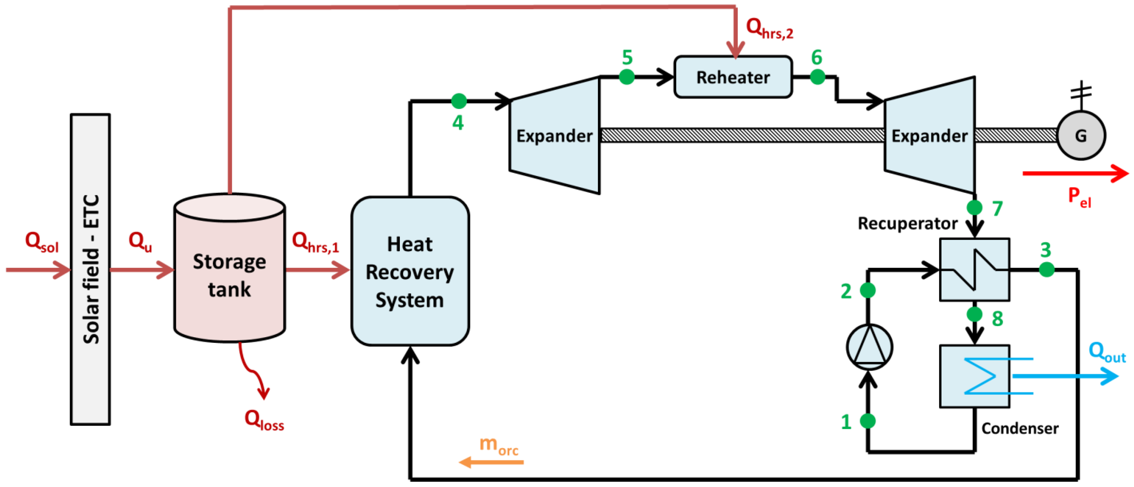
The two solar-driven ORCs of the present work are depicted in Figure 1 and Figure 2, respectively. Figure 1 displays the conventional solar-driven ORC with a recuperator, while Figure 2 depicts a system with reheating, which is suggested in this work. The working medium is selected to be cyclopentane as an efficient choice according to other studies [19,20]. In both examined cycles, the use of a recuperator is selected because it significantly increases efficiency, as has been stated in References [8,9].
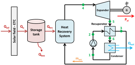
Figure 1.
The conventional solar-driven regenerative ORC.

Figure 2.
The suggested solar-driven regenerative ORC with reheating.
Both systems are fed by evacuated tube collectors (ETC), while there is a sensible thermal storage tank in order to store thermal heat during the day. ETCs are a proper choice for applying this system in the building sector [21] because they do not have requirements for tracking the sun during the day, thus leading to lower complexity. The sensible storage tank is an insulated one that stores the produced thermal energy from the solar field and the temperature level inside it is increased. At this point, it is essential to say that the working medium in the solar collectors’ field and the storage tank is selected to be thermal oil in order to achieve temperatures over 100 °C. More specifically, Therminol VP-1 is selected as a proper choice for the present solar system [22].
The ORCs operate with small superheating of ΔTsh = 5 K [23] in order not to work in very high-temperature levels. This assumption is reasonable because the increase in superheating is not so beneficial for the ORCs [24]. It is useful to state that this superheating regards the high-pressure expander in the reheating system. Moreover, in this work, the minimum temperature difference on the recuperator is chosen at ΔTrec = 5 K [23] and the pinch point in the heat recovery system at PP = 5 K [23].
The efficiency of the electrical generator is chosen at ηgen = 98%, the shaft mechanical efficiency ηm = 99%, the pump’s motor efficiency at ηmotor = 80%, and the pump’s isentropic efficiency at ηis,pump = 80% [23]. For the case of Figure 2 with the reheating, the inlet temperature of both expanders is selected to be the same (T4 = T6), a usual assumption that is done in reheating power cycles. Furthermore, the condenser temperature is selected to be at least 5 K higher than the ambient temperature for achieving a suitable heat rejection to the ambient. It is useful to state that the fluid from the condenser is a saturated liquid.
2.2. The Developed Mathematical Formulation
The present section includes the main equations that describe the behavior of the studied systems. These equations were inserted in the developed programs to conduct this work. Moreover, some extra typical equations for the thermodynamic properties of the unit were used. It is useful to state that the present mathematical formulation is written for the system with reheating (system in Figure 2), which is the new one. The modeling of the conventional systems (system in Figure 1) is a simpler case and thus its modeling is not given separately.
2.2.1. Modeling of the Solar System and Storage Tank
Below, the basic formulas for the mathematical description of the used models are presented. These equations mainly regard the definition of efficiencies.
The solar field thermal efficiency (ηcol) is given by the following expression [25]:
The useful heat product of the solar field (Qu) can be found as follows:
The collector incident solar energy (Qsol) is calculated according to the next expression:
The solar field aperture (Acol) and the irradiation incident angle on the collector area (GT) are used in the previous equation.
The energy balance in the thermal tank can be expressed according to the following expression:
The heat output to the ORC is described by the terms (Qhrs,1) and (Qhrs,2), while the thermal losses with the term (Qloss). It can be added that the thermal losses include the convective, radiation, and conductance parts. More specifically, the thermal losses of the tank (Qloss) can be calculated by the next equation:
The tank’s thermal loss coefficient is chosen at Utank = 0.5 W/m2 K, while the outer area is calculated according to the tank geometry. It is useful to state that in this work, the tank is divided into five mixing zones and in every zone, the proper energy balance is conducted. The tank is selected to be a cylindrical one with the height to be the same as the diameter. A deeper description of the detailed modeling can be found in Reference [26].
Furthermore, the stored thermal energy (Qstr) is written as:
The aforementioned equation is the energy balance in the storage fluid. The thermal oil density (ρ), specific heat capacity (cp), tank volume (V), tank mean temperature (Tst), and time (t) are used in the previous expression. It is also important to say that this formula is the core of the dynamic simulation of the system.
2.2.2. Mathematical Background for the Organic Rankine Cycle
The organic pump’s consumption (Wp) is written as below:
The specific enthalpy of the state-point (2) can be estimated using the pump isentropic efficiency (ηis,pump) as below:
The isentropic point (2,is) has enthalpy, which is calculated by using the high pressure of the system and the entropy of the state point (1). The electrical consumption of the motor that moves the compressor of the heat pump can be found as below:
The energy balance in the recuperator is calculated as:
Moreover, the minimum approach temperature is found on the cold side of the heat exchanger and thus the following expression can be written as:
The heat rejection to the ambient (Qout) is calculated as below:
It is also useful to highlight that the outlet of the condenser (state point 1) is chosen to be saturated liquid with low-pressure (pl).
The heat input in the HRS leads to the production of vapor with high pressure (ph) and 5 K superheating (state point 4). More specifically, the heat input in the heat recovery system (Qhrs,1) is expressed by the next formula:
The expansion in the high-pressure expander is described with the following isentropic efficiency (ηis,exp−1) definition:
The isentropic point (5,is) has medium pressure (pm) and entropy of the state point (4).
In this work, screw expanders are selected to be used based on the operating capacities. The isentropic efficiency of the high-pressure expander can be found with the developed formula of Astolfi [27]:
The parameters (Vr,1) and (Vout,1) are the volumetric ratio (Vr,1 = V5/V4) and the outlet specific volume (Vout,1 = V5).
The intermediate pressure (pm) is estimated as the geometric mean of the high-pressure (ph) and the low-pressure (pl). This is a usual assumption in thermodynamic cycles, which was tested in the present work and found to be acceptable. More specifically, it can be written as:
The reheater adds heating in the organic fluid until (T6 = T4). The heat input is given by the solar field and expressed as below:
The expansion in the high-pressure expander is described with the following isentropic efficiency (ηis,exp−2) definition:
The isentropic point (7,is) has low pressure (pl) and the specific entropy of the state-point (6). The isentropic efficiency of the low-pressure expander can be found with the developed formula of Astolfi [27].
The parameters (Vr,2) and (Vout,2) are the volumetric ratio (Vr,2 = V7/V6) and the outlet specific volume (Vout,2 = V7).
The produced work by the high-pressure expander (Wexp−1) is given as:
The produced work by the low-pressure expander (Wexp−2) is given as:
The produced electricity by the electrical generator (Pgen) is given below:
The produced net electricity of the ORC (Pel) is given as:
The ORC’s efficiency (ηORC) is given as:
The system efficiency (ηsys) is given as:
2.2.3. Yearly Analysis and Financial Evaluation
The yearly electricity production (Eel) is calculated as below:
The yearly solar irradiation input (Esol) is calculated as below:
The yearly system efficiency (ηsys,y) is calculated as below:
The capital cost of the investment (C0) is given below:
The yearly cash flow of the system (CF) is given as follows:
The yearly operation and maintenance costs (O&M) are chosen to be 0.5% of the investment cost.
The definition of the simple payback period (SPP) is given as follows:
The definition of the net present value of the investment (NPV) is given as follows:
where (N) is the project lifetime and (d) the discount factor.
2.3. Simulation of the Developed Models
The present investigation is completed with the software Engineering Equation Solver [18]. Two models, one for steady-state and one for dynamic analysis, were developed. In the dynamic analysis, climate conditions for the location of Athens in Greece and more information about them can be found in Ref. [26]. It is useful to state that the ETCs are selected to have a slope of 38°, which is the same as the latitude of Athens for maximizing the incident solar potential on a yearly basis. The equations of Section 2.2 have been used in the developed models. Proper discretization was performed in order to make the results independent of the time step. The condenser temperature is slated to be 5 K over the maximum daily ambient temperature in order to achieve a proper operation of the ORC. Moreover, it is useful to state that the system was studied for 12 representative days—one day for each month in order to properly simulate the annual performance of the solar-fed configuration.
In the first part of the analysis, a simple comparison of the two examined ORCs in steady-state conditions is performed by selecting nominal electricity capacity at 15 kW. The next step is the dynamic analysis of the two systems for a typical day. The final evaluation of the system is conducted on a yearly basis by investigating two critical parameters—the saturation temperature of the ORC and the nominal electricity capacity of the ORC. The results are evaluated in terms of energy efficiency and financial indexes such as SPP and NPV. The final global optimum choice is the selected one that maximizes the investment NPV.
In the last part of this section, Table 1 and Table 2 summarize the main data of the present simulation. Table 1 includes the input parameters of the thermodynamic analysis and the system design, while Table 2 summarizes the data of the financial investigation. An assumption of this work is the selection of the solar field area at 300 m2 and the storage tank at 5 m3.

Table 1.
Details of the thermodynamic analysis and the solar field.
Table 2.
Details of the economic evaluation.
Moreover, It is critical to say that the thermodynamic model for simple ORC has been validated in our previous works [28]. However, it is important to again provide validation evidence in order to be clear about the accuracy of the developed model. More specifically, the developed model has been compared with experimental results from Reference [29]. In order to perform a suitable validation, all the proper modifications of the existing model have been done in order to be in accordance with the “boundary conditions” of the experimental setup in Reference [29]. Table 3 summarizes the comparative results for different working fluids and it has to be said that the deviation in the electricity yield was found close to 0.6% and thermodynamic efficiency close to 0.5%. These are small deviations that indicate the high accuracy of the developed model.
Table 3.
Validation of the simple ORC system with experimental data [29].
3. Results and Discussion
Section 3 presents the results of this work for steady-state conditions and the time-dependent investigation. Moreover, the results are deeply analyzed and discussed.
3.1. Thermodynamic Analysis of the ORCs in the Steady-State Analysis
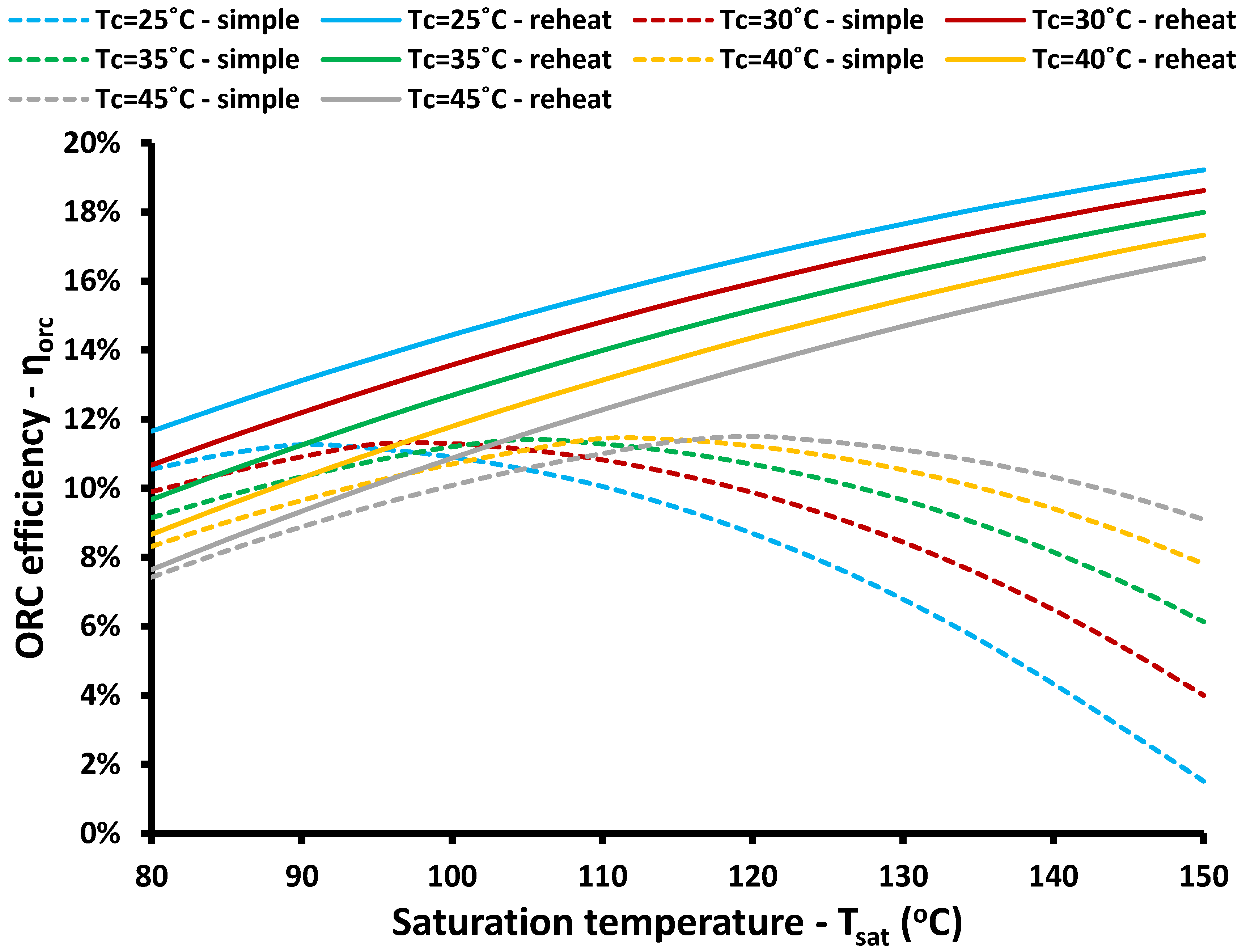
The first step in this work is the thermodynamic analysis of the reheat cycle and the conventional (simple) cycle. Figure 3 illustrates the ORC thermodynamic efficiency for different operating conditions for both the reheat and simple cycle. More specifically, the saturating temperature in the ORC’s HRS and the condenser temperature are the studied parameters. Practically, these temperature levels are associated with the operating pressure levels and the pressure ratio. In the present study, isentropic efficiency is dependent on the expander pressure ratio, a critical fact that affects a lot of the results. More specifically, Figure 3 indicates that for every condenser temperature, the curves of the simple cycle are maximized for a specific saturation temperature and after this point, the efficiency curves have decreasing rates. Practically, after this limit, the increase in saturation temperature increases the pressure ratio a lot, something that reduces the efficiency of the expander and consequently of all the system. On the other hand, this behavior is not observed for the case with two expanders because a turbine has a smaller pressure ratio (the square root of the respective value in the simple case). This fact makes the expanders of the reheating system achieve high performance, and thus the reheating system has higher performance for higher saturation temperatures, a result in accordance with the efficiency of a thermodynamic cycle according to the “Carnot Cycle” behavior. It is useful to state that lower condenser temperature increases the efficiency of the reheat cycle, while for the simple cycle, there is a different behavior. More specifically, in low saturation temperatures, both cycles have higher performances for lower condenser temperatures, while for high temperatures, the low condenser temperature reduces the isentropic efficiency and consequently the global system efficiency a lot. The aforementioned analysis indicates that the system with one expander faces critical problems when it has to operate with high-pressure ratios and is thus a limitation of this configuration. Special expander designs are needed in every case in order to achieve suitable efficiency.
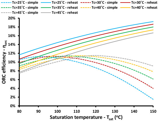
Figure 3.
ORC thermodynamic efficiency for the heat and simple cycles.
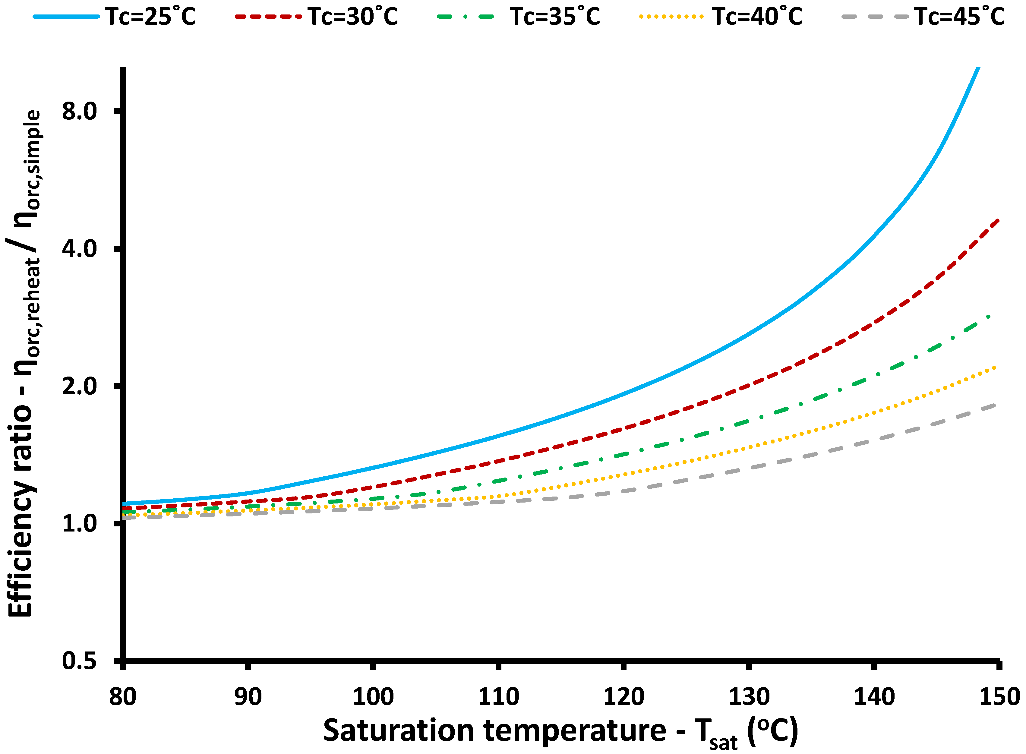
Figure 4 exhibits the ratio of the ORC thermodynamic efficiencies for the reheating system to the simple system. It was observed that for all the examined operating scenarios, this ratio takes values over 100% and thus the reheating case is a more efficient choice than the conventional simple cycle. The increase of this ratio is more intense in high saturation temperatures and also in lower condenser temperature levels. These results are in accordance with the aforementioned analysis of Figure 3.
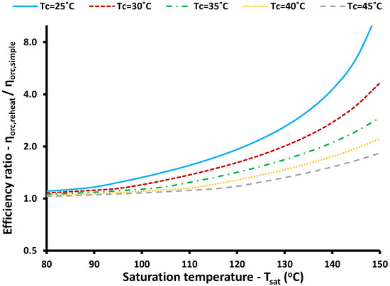
Figure 4.
Ratio of the thermodynamic efficiency of the reheat case to the simple case (vertical axis is in a logarithmic scale).
3.2. Dynamic Comparison for a Typical Day
The second stage in the present study is the dynamic analysis of the unit. A typical sunny day is selected to be examined in June (172 day of the year) and the results are presented below. Figure 5 depicts the solar collector efficiency, the ORC thermodynamic efficiency, and the system efficiency on a daily basis for different saturation temperature levels for the reheat system. The nominal electricity capacity is selected at 15 kW, while the heat rejection temperature is selected at 36 °C in order to be 5 K higher than the maximum daily temperature of the day [26]. According to Figure 5, a higher saturation temperature reduces the solar thermal efficiency because the system operates at higher temperatures and thus the solar field operates also in higher temperatures, a fact that leads to greater thermal losses and lower collector thermal efficiency. On the other hand, higher saturation temperature leads to higher thermodynamic efficiency, a result in accordance with Figure 3. The system efficiency is found to be maximized for a saturation temperature at 140 °C with 7.13%, while the ORC efficiency is 17.03% and collector efficiency 42.02%. The maximization of the system efficiency in an intermediate temperature is a result of the different behavior of the collector and the ORC efficiencies with the saturation temperature. In other words, a higher saturation temperature enhances the ORC efficiency and reduces the collector efficiency. System efficiency, which is proportional to the product of these parameters, is maximized in an intermediate value, a critical conclusion that indicates the need for a detailed optimization procedure.
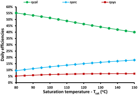
Figure 5.
The influence of the saturation temperature on different efficiencies (reheat case—Pel,nom = 15 kW).
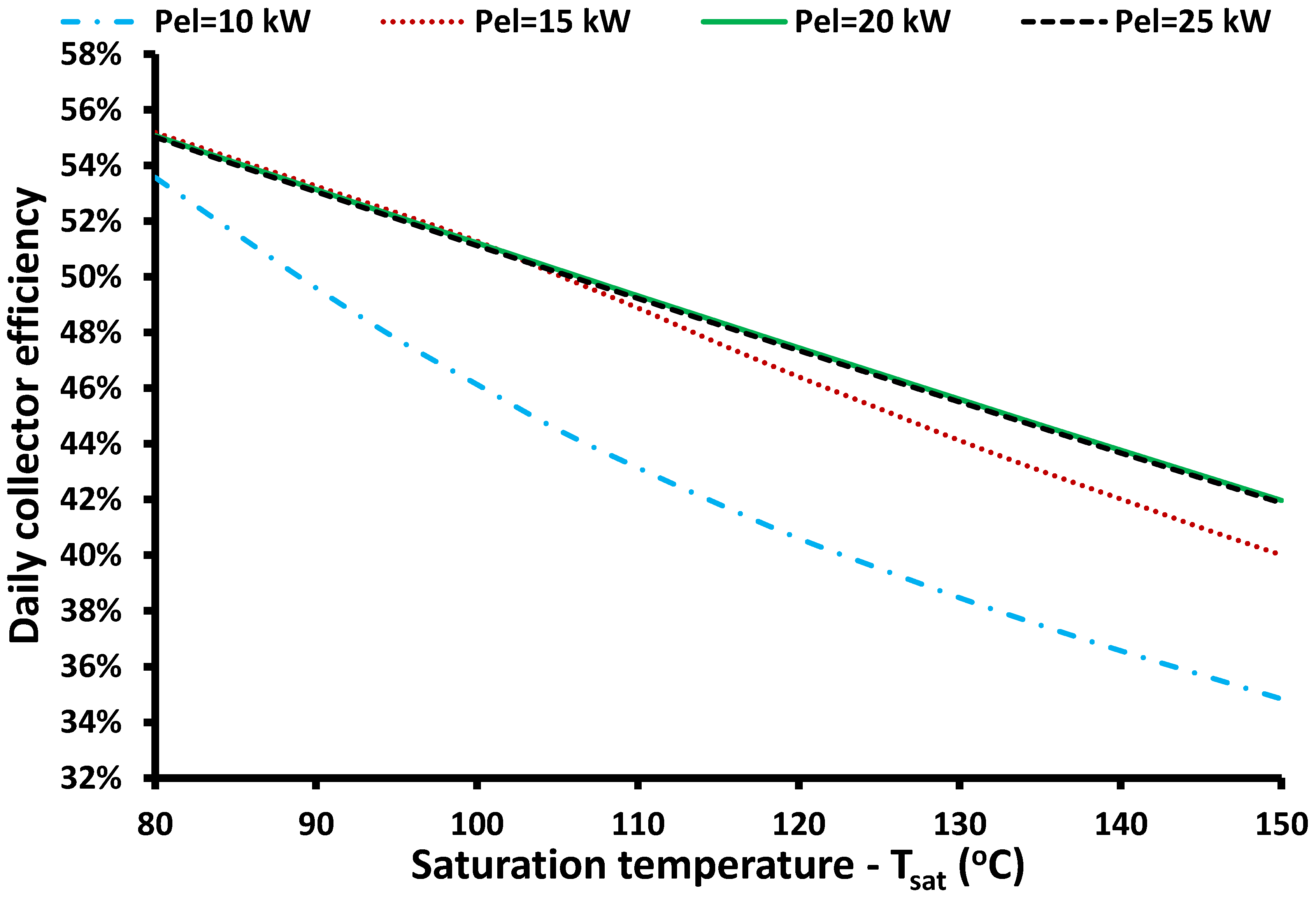
After an initial evaluation, the next step is the parametric analysis for different combinations of the saturation temperature and the nominal electricity capacity. It is useful to state that the nominal electricity capacity of the system is selected at 10, 15, 20, and 25 kW. Figure 6 depicts the daily solar efficiency for the different examined design scenarios of the reheating system. It is obvious that a higher saturation temperature reduces the daily collector efficiency. Moreover, in cases with lower electricity capacity, the collector efficiency is lower and its reduction is also more intense with the augmentation of the saturation temperature. For the scenario of 10 kW capacity, solar collector efficiency is significantly reduced; the fact proves that in this case, the system operates at high-temperature levels where there are high thermal losses. Practically, low electricity production means low heat extraction from the tank to the HRS, something that leads to great storage in the tank associated with high operating temperatures in solar collectors.
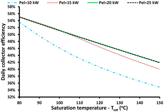
Figure 6.
Daily collector efficiency for different combinations of saturation temperature levels and electricity capacities (reheat case).
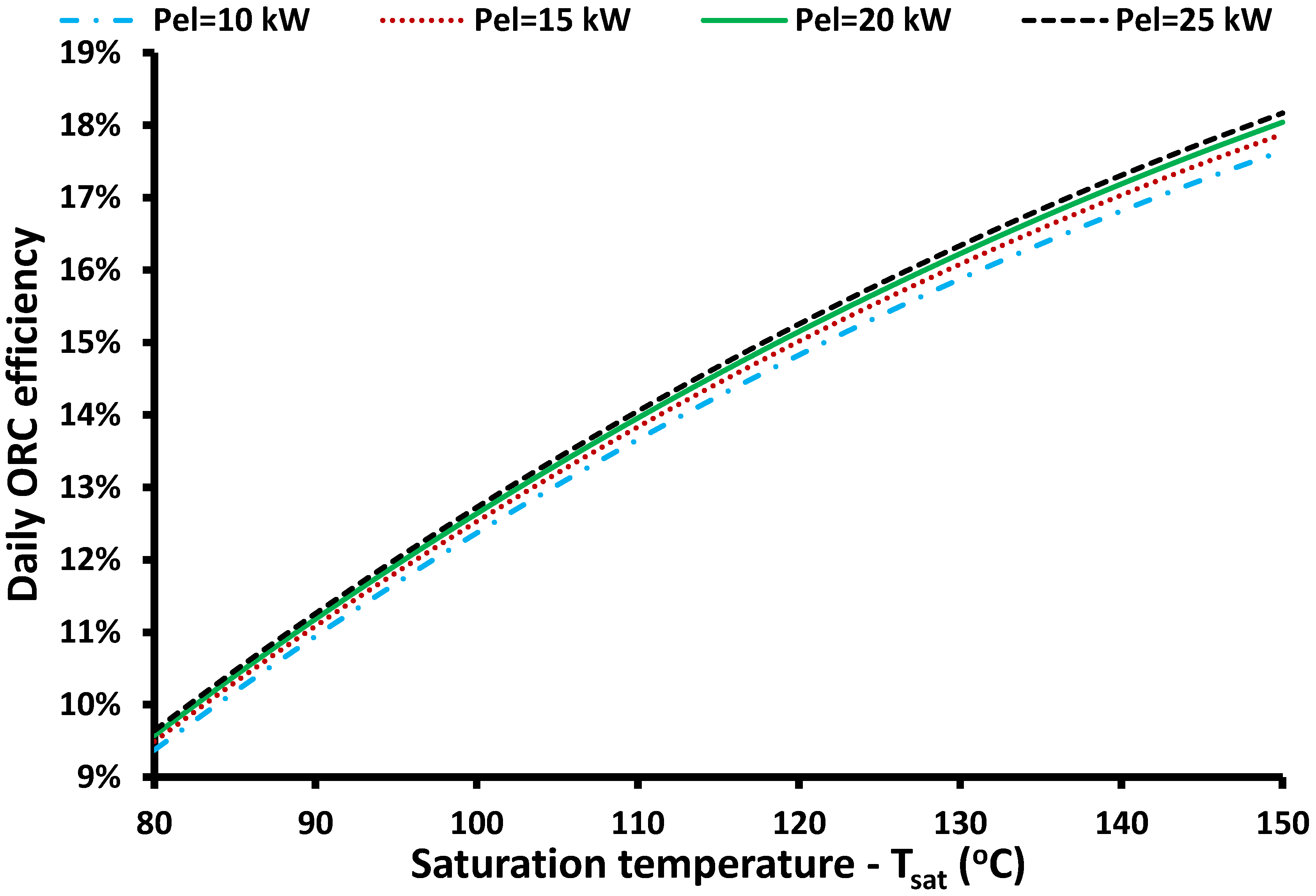
Figure 7 depicts the results of the ORC thermodynamic efficiency. Higher saturation temperature enhances the ORC performance for the reheating system, a reasonable result according to the aforementioned analysis (see Figure 3). The interesting result is that the ORC is not highly influenced by the electricity capacity of the unit. However, it is useful to state that higher electricity capacity increases the thermodynamic efficiency of the system.
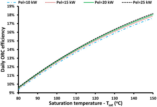
Figure 7.
Daily thermodynamic efficiency of the ORC for different combinations of saturation temperature levels and electricity capacities (reheat case).
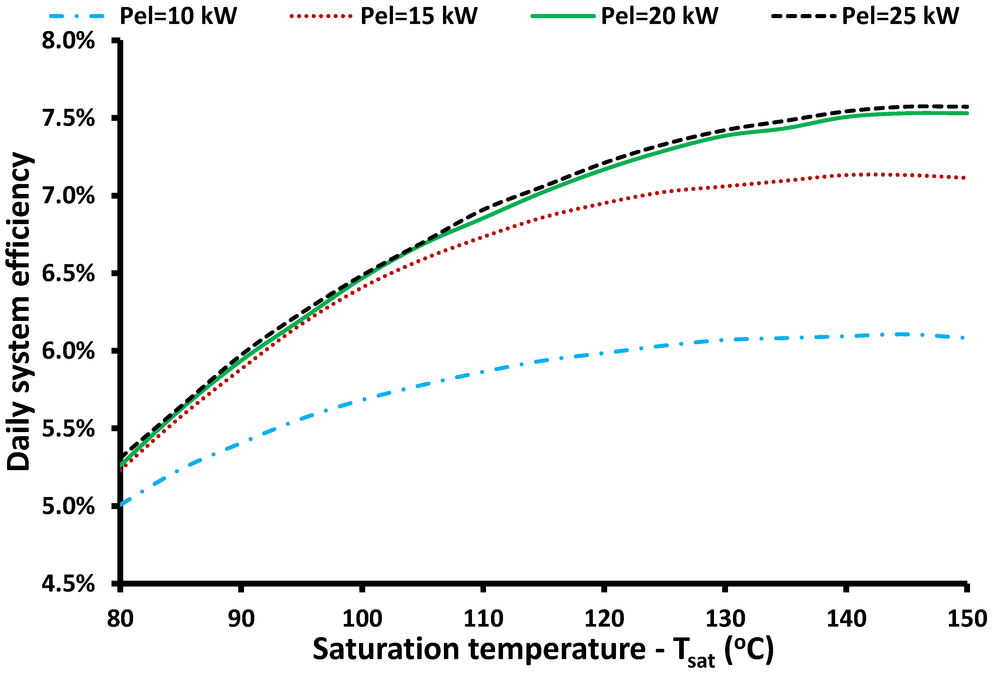
Figure 8 demonstrates the system efficiency for the different designed cases of the reheating system. The system efficiency has higher values when the saturation temperature and electricity capacity increase. It is very interesting to state that the increase of the capacity is very important and more specifically the case of 10 kW leads to significantly low yield, while 20 kW leads to an adequate yield. Moreover, the saturation temperature is a very important parameter and has to be over 120 °C because, after this limit, its increase is not as effective in the system. Moreover, the higher saturation temperatures may create manufacturing difficulties or increase costs. In any case, operation in the range of 120–130 °C is an easy manufacturing choice that can lead to sustainable designs.
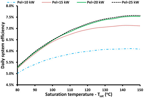
Figure 8.
Daily system efficiency for different combinations of saturation temperature levels and electricity capacities (reheat case).
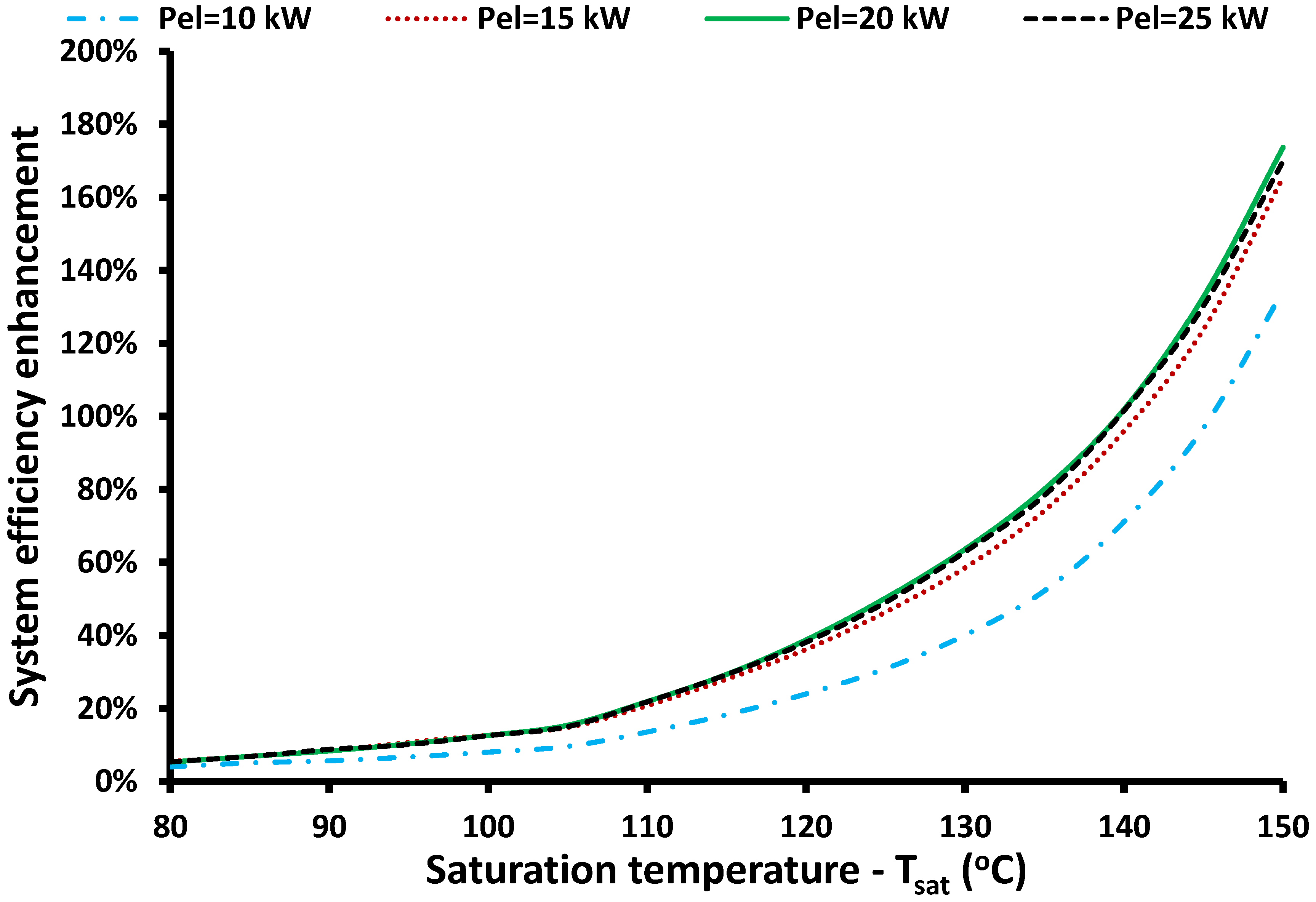
In the last part of the present section, system efficiency enhancement of the reheating unit compared to the simple unit is presented for different design scenarios; the results are presented in Figure 9. It is obvious that the reheating system is a more efficient choice for all the studied cases. The enhancement reaches up to 174% for 20 kW electricity capacity and 150 °C saturation temperature. It is also useful to highlight that the enhancement is higher for greater saturation temperatures and the increase is more intense after 110 °C. The highest enhancement is found for the 20 kW case, with the other cases in the following sequence: 25 kW, 15 kW, and 10 kW.
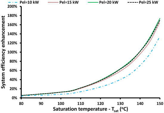
Figure 9.
Daily system efficiency enhancement with the reheat system compared to the simple system for different combinations of saturation temperature levels and electricity capacities.
3.3. Yearly Energetic Performance
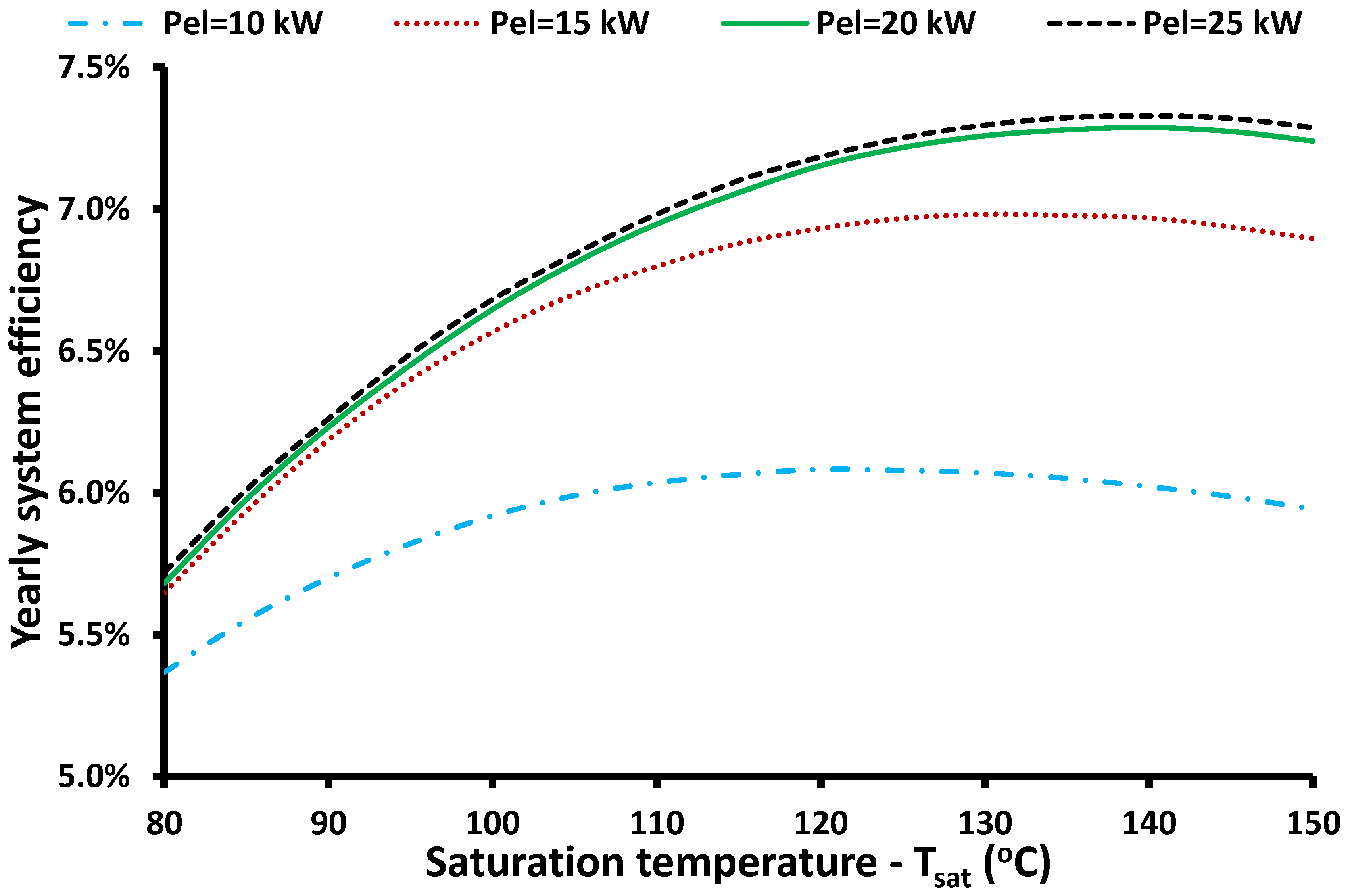
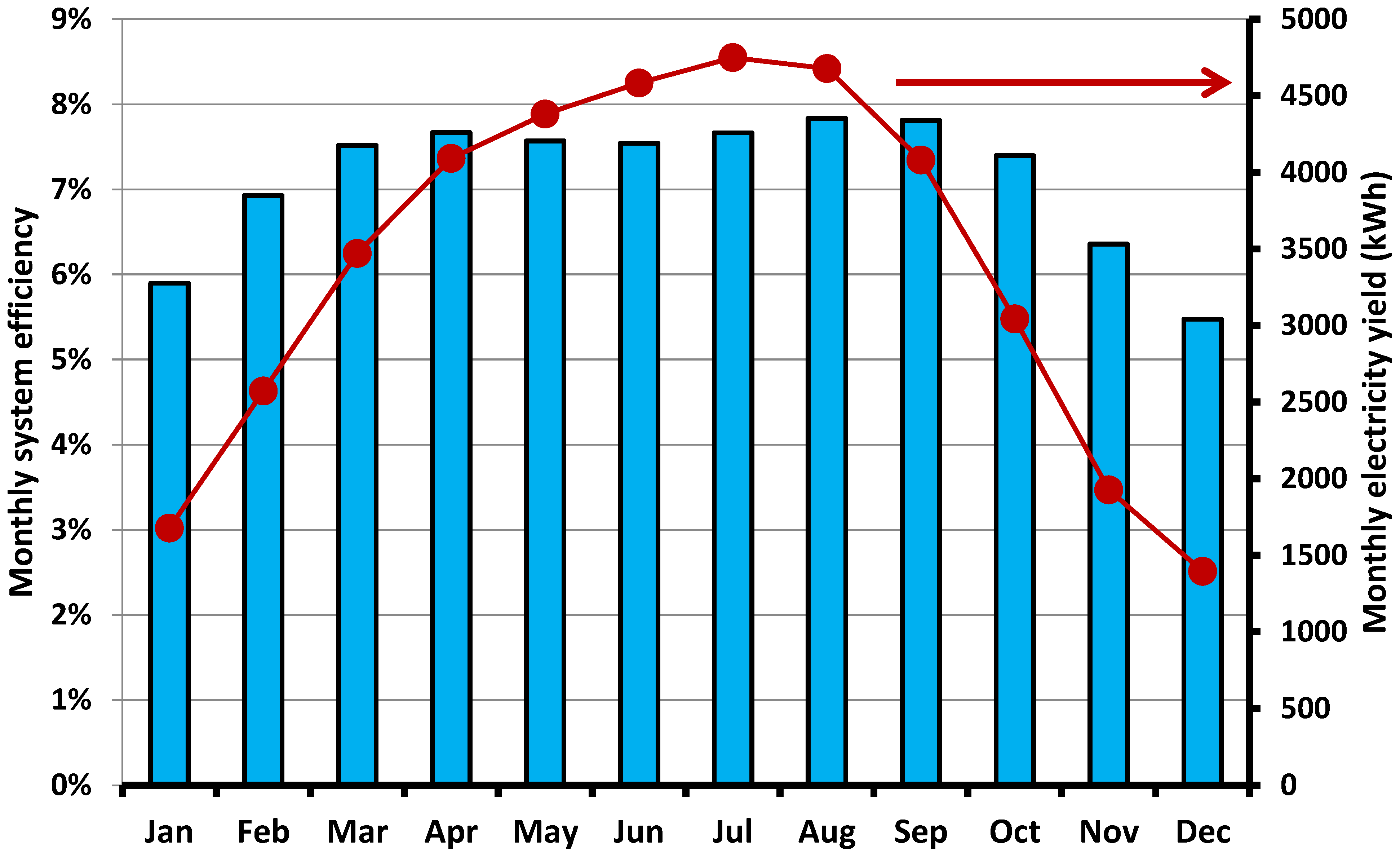
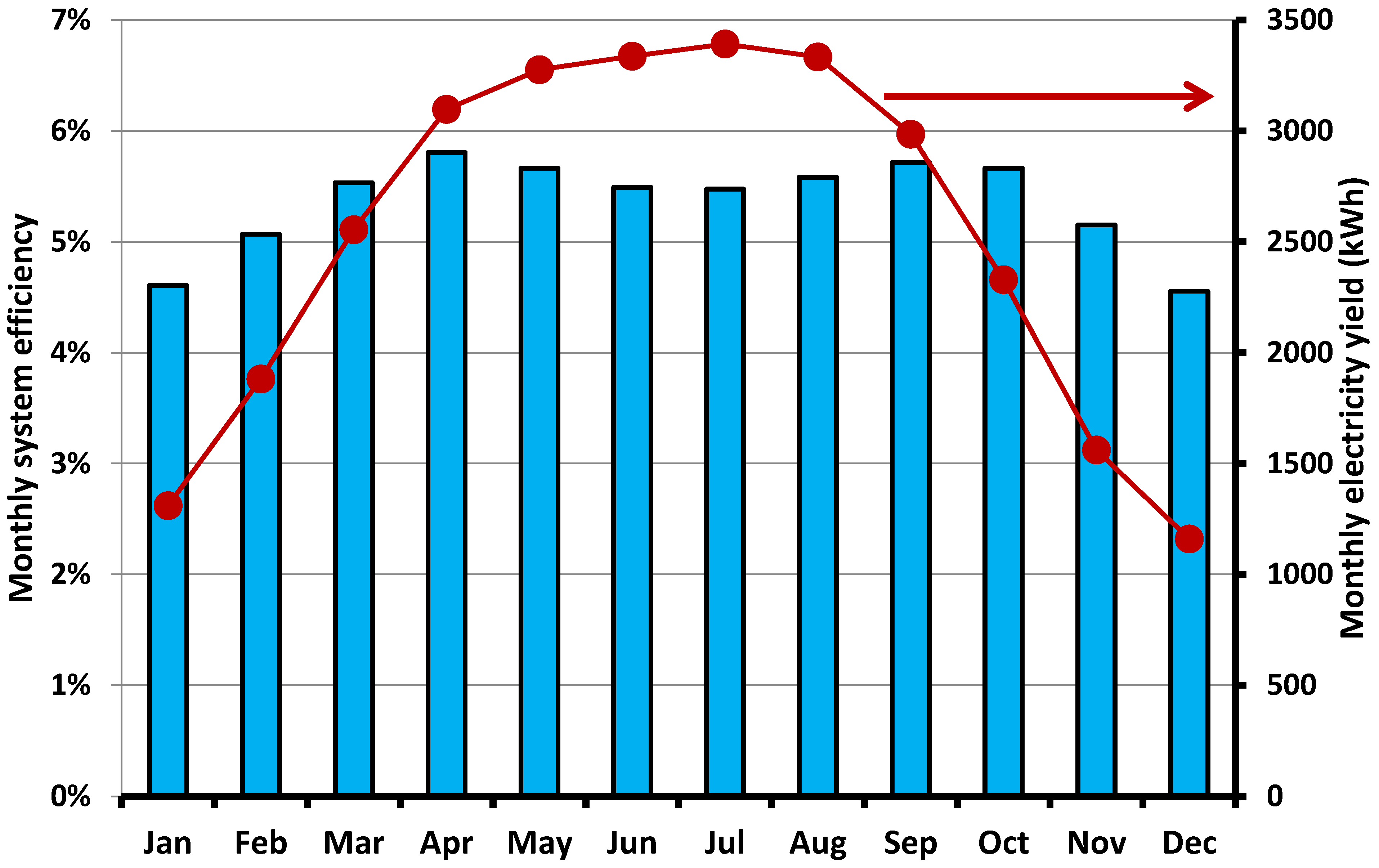
The annual investigation of the studied configurations is very important in order to define their real performance. The climate conditions in Athens are selected for this analysis. One typical data for every month was examined, which is a usual methodology for solar thermal application analysis. Figure 10 displays the results of the yearly system efficiency of the reheat system for different electricity capacities and saturation temperatures. It is useful to state that a higher capacity leads to a higher yield, a reasonable result because greater nominal capacity offers the possibility to produce higher amounts of electrical energy, especially in summer when there is adequate solar potential. The global maximum system efficiency was found for 25 kW electricity capacity and 140 °C saturation temperature. In this design, system efficiency was 7.33%, ORC efficiency 18.09%, and collector efficiency is 40.70%. It is also useful to state that for this case, electricity production yield was maximized at 40.6 MWh. Figure 11 displays the monthly variation of the electricity yield production and system efficiency. It can be said that system efficiency is maximized in August, while yield production is maximized in July. Generally, the system has a higher performance in the summer compared to winter, an acceptable result because in the summer there is higher solar potential and the solar rays are more “vertical” in the ETC aperture.
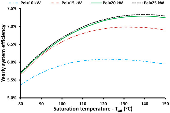
Figure 10.
Yearly system efficiency for the reheat ORC case for different combinations of saturation temperature levels and electricity capacities.
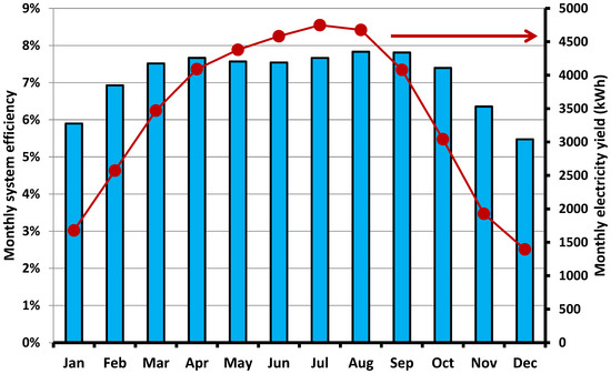
Figure 11.
Monthly system efficiency and electricity yield for the optimum case of the reheat ORC case according to system efficiency maximization (Tsat = 140 °C − Pel = 25 kW).
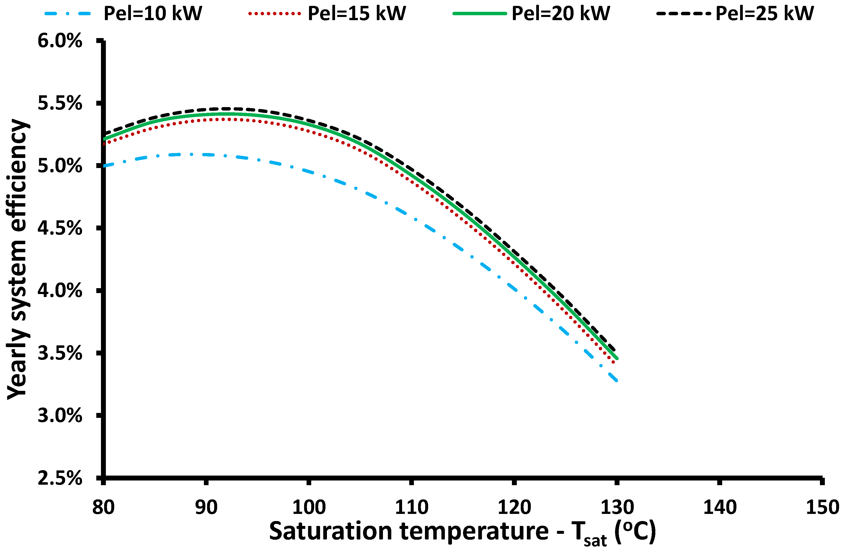
Figure 12 displays the yearly performance of the simple system, while Figure 13 shows the monthly performance for the optimum case. The maximum saturation temperature is selected to be up to 130 °C in order to avoid very high expansion ratios in the system. In addition, Figure 12 indicates that in high saturation temperatures, the system efficiency is significantly reduced, so this range is not interesting. According to Figure 12, the optimum saturation temperature of the ORC is found at 90 °C, while the capacity of 25 kW is the best choice. For this scenario, the yearly system efficiency is 5.45%, cycle efficiency is 10.81%, and collector efficiency is 50.51%. The electricity yield for this case is found at 30.2 MWh. Figure 13 shows that monthly efficiency is maximized in April and monthly yield in July.
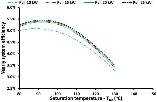
Figure 12.
Yearly system efficiency for the simple ORC case for different combinations of saturation temperature levels and electricity capacities.

Figure 13.
Monthly system efficiency and electricity yield for the optimum case of the simple ORC case according to system efficiency maximization (Tsat = 90 °C − Pel = 25 kW).
The energetic comparison of the two optimum scenarios indicates that the reheating system leads to 34.5% higher performance, which is an important enhancement. This result clearly shows that on a yearly basis, the suggested reheating configuration can lead to a significant enhancement in solar irradiation harvesting, which can make solar-fed ORC a viable choice for achieving the sustainable development goals of 2030 [30].
3.4. Financial Performance
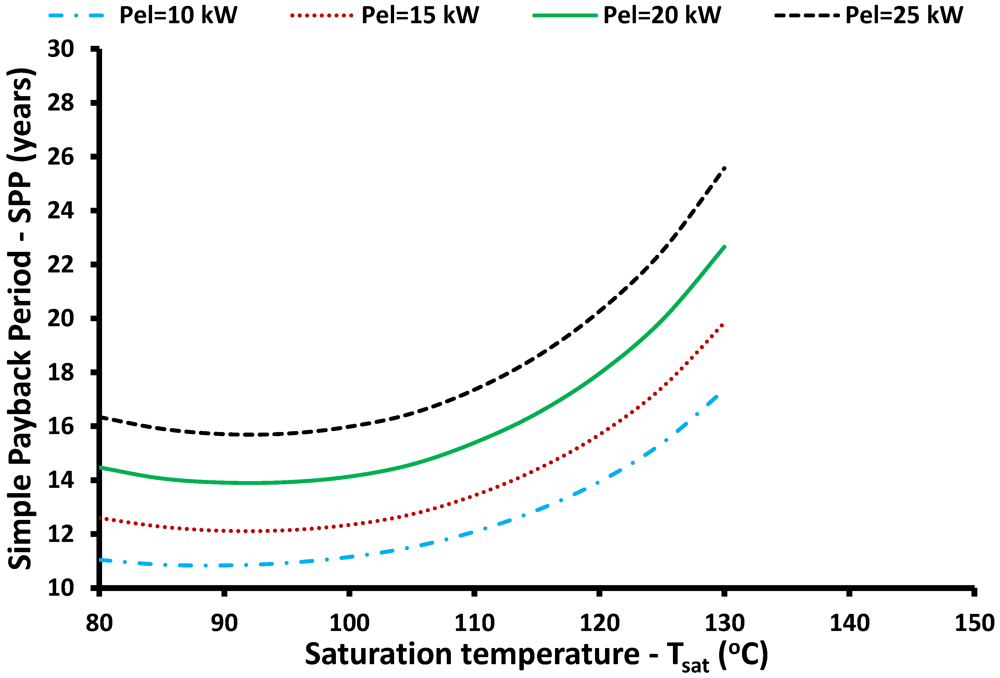
The last step in the present work is the presentation of the financial analysis of the studied solar-fed ORCs. Figure 14 depicts the simple payback period of the reheat ORC case for different scenarios. It can be said that the lower electricity capacity reduces the SPP, while the optimal saturation temperature is in the range of 120–140 °C. More specifically, the global minimum SPP is found for 10 kW and 120 °C at 9.63 years. For higher capacities, the optimum saturation temperature presents a small increase according to the results.
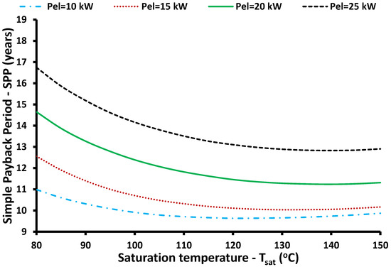
Figure 14.
Simple payback period for the reheat ORC case for different combinations of saturation temperature levels and electricity capacities.
Figure 15 depicts the SPP for the simple ORC and it is obvious that the global minimum value is found for 10 kW and 90 °C saturation temperature at 10.84 years. For all the capacities, the SPP is minimized for 90 °C, which is an interesting result because it is significantly lower than the respective optical values for the reheat system (120–140 °C). Moreover, an interesting result is that for both cases, the minimum capacity is the best one according to the SPP criterion.
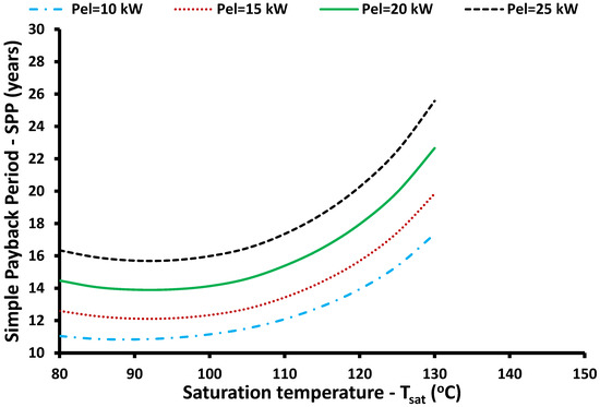
Figure 15.
Simple payback period for the simple ORC case for different combinations of saturation temperature levels and electricity capacities.
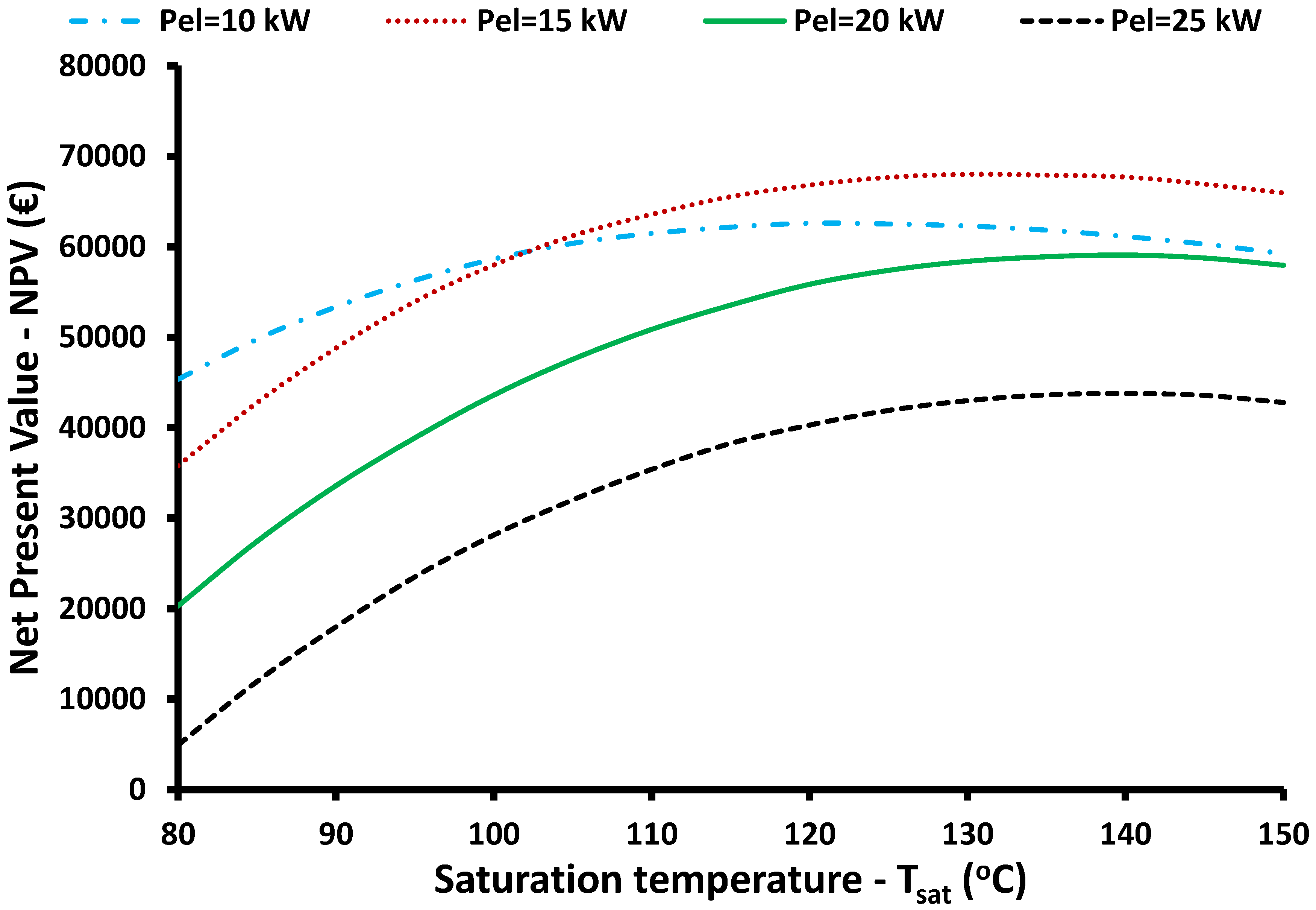
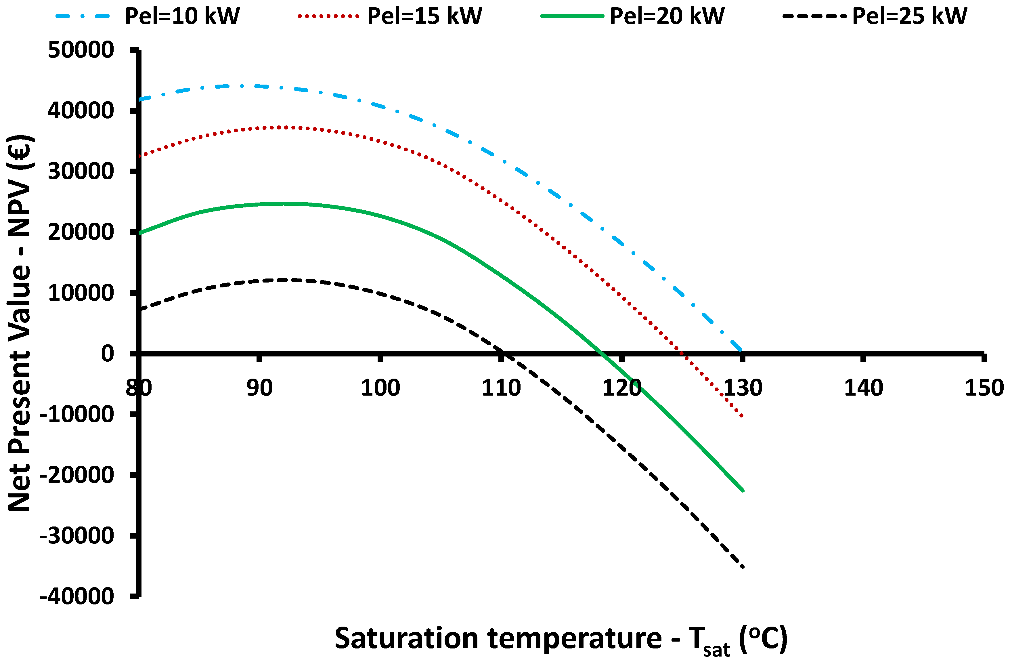
Figure 16 and Figure 17 illustrate the NPV of the examined investments for the heat and simple scenarios, respectively. The global maximum NPV for the reheat system is found for 15 kW capacity and 130 °C saturation temperature at 68 k€. On the other hand, the global maximum NPV for the simple case is found for 10 kW and 90 °C saturation temperature at 44 k€.
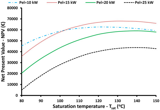
Figure 16.
Net present value for the reheat ORC case for different combinations of saturation temperature levels and electricity capacities.
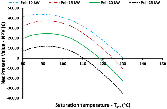
Figure 17.
Net present value for the simple ORC case for different combinations of saturation temperature levels and electricity capacities.
At the end of this section, the optimal cases according to the NPV maximization are summarized in Table 4. It can be said that all the indexes are better for the reheat ORC, compared to the simple ORC. Thus, it is clear that the suggested system is an efficient and viable one compared to the conventional scenario. Thus, it is suggested that the reheat ORC is an attractive choice for solar-driven ORCs. It is essential to state that for these cases, system efficiency is 6.98% for the reheat case and 5.09% for the simple cases, presenting an enhancement of 37.1%. The NPV is 68 k€ for the reheat case and 44 k€ for the simple case, something that indicates 24 k€ net gain from the investment in the reheating system.
Table 4.
Comparison of the optimum scenarios for maximization of the NPV.
3.5. Discussion
The present work compares two different types of solar-driven ORCs. The conventional system is compared to the reheat design, which is a novel cycle. This cycle is found to be more efficient than the conventional one, an important result that indicates that the reheat ORC can be a sustainable technology. It has been found that the energy optimization of the reheat ORC system leads to a global maximum efficiency of 7.33% on a yearly basis, compared to 5.45% of the conventional system. This enhancement is important and about 34.4%. Financial optimization leads to optimal systems financially, with the reheat system to present 6.98% yearly system efficiency and the simple system 5.09%. Again, there is a significant enhancement in efficiency with the reheat design which is 37.1%.
At this point, it is useful to state the performance of other similar configurations in the literature in order to discuss the results of the present work in energy terms. Twomey et al. [31] conducted a dynamic analysis on solar ORC with Dymola and found efficiency of 3.5%. In another study, Wang et al. [32] conducted a thermoeconomic optimization about a solar-driven ORC with ETC and concluded a 5.5% efficiency. In another work, Ramos et al. [33] conducted an optimization of a unit with ETC coupled to ORC and found 5.5% efficiency for the city of Athens in Greece. In addition, they indicated that the use of evacuated tube collectors is a better choice than the use of flat plate collectors.
The aforementioned literature indicates that the obtained values of the present work for the conventional system (5.45%) are very close to the values of the references [32,33] for the system efficiency. This fact verifies that the present work estimates with high accuracy the simple ORC performance and is a very important point of verification. Therefore, the obtained enhancement with the reheat ORC (7.33%) provides clear enhancement, compared to the usual values of the conventional ORCs, taking into account the present work, as well as other works from the literature.
4. Conclusions
The goal of the present work is the analysis of a solar-fed organic Rankine cycle with reheating and its comparison with the conventional organic Rankine cycle. Both ORCs include a recuperator after the expander device, while the solar field consists of evacuated tube collectors. The comparative analysis is conducted mainly on dynamic conditions with a created model in Engineering Equation Solver. The analysis is energetic and economic for the weather data of Athens. Below, the most valuable conclusions are briefly presented:
- -
- The reheating system presents higher performance mainly due to the lower expansion ratio in every expanding device and consequently to higher isentropic efficiency.
- -
- For the reheat ORC, the global maximum system efficiency is found for 25 kW electricity capacity and 140 °C saturation temperature. The yearly system efficiency is 7.33%, ORC efficiency is 18.09%, and solar field efficiency is 40.70%.
- -
- For the simple ORC, the global maximum system efficiency is found for 25 kW electricity capacity and 90 °C saturation temperature. The yearly system efficiency is 5.45%, ORC efficiency is 10.81%, and solar field efficiency is 50.51%.
- -
- The optimum financial capacity is 15 kW for the reheat case and 10 kW for the simple case. The optimum saturation temperature is 130 °C for the reheat system and 90 °C for the simple case.
- -
- It is important to state that the optimum financial designs are found for the smaller capacities, while these present lower efficiency than higher capacities. This result indicates that the increase in capacity does not lead to a significant energy yield increase in order to overcome the extra cost due to the extra capacity.
- -
- It is useful to highlight that the results of this work indicate that the reheat system can operate in higher saturation temperatures compared to the simple system.
- -
- For optimum cases according to the NPV maximization, system efficiency for the reheat system is 6.98%, presenting an increase of 37.1% compared to the conventional case.
- -
- The maximum NPV for the reheat ORC is found at 68 k€, while it is 44 k€ for the simple ORC.
- -
- In the future, this system can be investigated with different working fluids (e.g., mixtures), phase change materials in storage devices, and other heat sources. Biomass and concentrating solar collectors are interesting choices that can be checked with the ORC reheat cycle.
Author Contributions
Conceptualization, E.B.; methodology, E.B. and P.L.; software, E.B., P.L. and C.T.; investigation, E.B.; writing—original draft preparation, E.B., P.L. and C.T.; writing—review and editing, E.B., P.L. and C.T.; supervision, C.T. All authors have read and agreed to the published version of the manuscript.
Funding
This research received no external funding.
Institutional Review Board Statement
Not applicable.
Informed Consent Statement
Not applicable.
Data Availability Statement
Data available after request.
Conflicts of Interest
The authors declare no conflict of interest.
Nomenclature
| A | Area, m2 |
| C0 | Investment cost, € |
| c1 | Coefficient of equation 16, - |
| c2 | Coefficient of equation 21, - |
| CF | Cash flow, € |
| d | Discount factor, % |
| Eel | Yearly electricity yield, kWh |
| Esol | Yearly solar yield, kWh |
| GT | Solar incident irradiation, W/m2 |
| h | Specific enthalpy, kJ/kg |
| Kcol | Collector specific cost, €/m2 |
| Ktank | Tank specific cost, €/m3 |
| KORC | Thermodynamic cycle’s specific cost, €/kW |
| mORC | Mass flow rate of the organic fluid, kg/s |
| N | System life span, years |
| NPV | Net present value, € |
| O&M | Cost for operation and maintenance, € |
| p | Pressure, bar |
| Pel | Net electricity production, kW |
| Pgen | Generator electrical production, kW |
| Ppump | Pump electricity demand, kW |
| Qloss | Tank thermal losses, kW |
| Qhrs | Heat input in the heat recovery system, kW |
| Qu | Useful heat production, kW |
| Qout | Heat rejection, kW |
| Qsol | Solar energy rate, kW |
| PP | Pinch Point in the heat recovery system, K |
| SPP | Simple payback period, € |
| T | Temperature, K |
| Utank | Thermal loss coefficient, W/m2 K |
| V | Storage system volume, m3 |
| Vr | Volumetric ratio of the expander, - |
| Vout | Specific volume in the expander outlet, m3/kg |
| Wexp | Work production of the expander, kW |
| Wpump | Work consumption in the pump, kW |
| Greek Symbols | |
| ΔTrec | Approach Temperature in the recuperator, K |
| ΔTsh | Superheating in the high-pressure expander inlet, K |
| ηcol | Collector thermal efficiency, - |
| ηgen | Electrical generator efficiency, - |
| ηis,exp | Expander isentropic efficiency, - |
| ηis,pump | Pump isentropic efficiency, - |
| ηm | Mechanical efficiency, - |
| ηmotor | Motor efficiency, - |
| ηORC | Organic Rankine cycle efficiency, - |
| ηsys | System efficiency, - |
| ηsys,y | Yearly system efficiency, - |
| Subscripts and Superscripts | |
| am | Ambient |
| c | Condenser |
| col | Collector |
| fluid | Working fluid |
| is | Isentropic |
| h | High |
| l | Low |
| m | Medium |
| nom | Nominal |
| sat | Saturation |
| simple | Simple—conventional cycle |
| st | Storage |
| opt | Optimum |
| reheat | Reheating |
| y | Yearly |
| Abbreviations | |
| ETC | Evacuated tube collector |
| HRS | Heat recovery system |
| ORC | Organic Rankine cycle |
References
- Sanchez, E.; Ordonez, A.; Sánchez, A.; Garcia Ovejero, R.; Parra-Dominguez, J. Exploring the Benefits of Photovoltaic Non-Optimal Orientations in Buildings. Appl. Sci. 2021, 11, 9954. [Google Scholar] [CrossRef]
- Loni, R.; Najafi, G.; Bellos, E.; Rajaee, F.; Said, Z.; Mazlan, M. A review of industrial waste heat recovery system for power generation with Organic Rankine Cycle: Recent challenges and future outlook. J. Clean. Prod. 2021, 287, 125070. [Google Scholar] [CrossRef]
- Yang, M.; Wang, Z.; Yang, J.; Yuan, G.; Wang, W.; Shi, W. Thermo-economic analysis of solar heating plant with the seasonal thermal storage in Northern China. Sol. Energy 2022, 232, 212–231. [Google Scholar] [CrossRef]
- Gevel, T.; Zhuk, S.; Leonova, N.; Leonova, A.; Trofimov, A.; Suzdaltsev, A.; Zaikov, Y. Electrochemical Synthesis of Nano-Sized Silicon from KCl–K2SiF6 Melts for Powerful Lithium-Ion Batteries. Appl. Sci. 2021, 11, 10927. [Google Scholar] [CrossRef]
- Loni, R.; Mahian, O.; Markides, C.N.; Bellos, E.; le Roux, W.G.; Kasaeian, A.; Najafi, G.; Rajaee, F. A review of solar-driven organic Rankine cycles: Recent challenges and future outlook. Renew. Sustain. Energy Rev. 2021, 150, 111410. [Google Scholar] [CrossRef]
- Loni, R.; Mahian, O.; Najafi, G.; Sahin, A.Z.; Rajaee, F.; Kasaeian, A.; Mehrpooya, M.; Bellos, E.; le Roux, W.G. A critical review of power generation using geothermal-driven organic Rankine cycle. Therm. Sci. Eng. Prog. 2021, 25, 101028. [Google Scholar] [CrossRef]
- Macchi, E.; Astolfi, M. Organic Rankine Cycle (ORC) Power Systems; Woodhead Publishing Series in Energy; Woodhead Publishing: Sawston, UK, 2017. [Google Scholar]
- Tian, Z.; Gan, W.; Qi, Z.; Tian, M.; Gao, W. Experimental study of organic Rankine cycle with three-fluid recuperator for cryogenic cold energy recovery. Energy 2022, 242, 122550. [Google Scholar] [CrossRef]
- Wu, C.; Wang, S.S.; Li, J. Parametric study on the effects of a recuperator on the design and off-design performances for a CO2 transcritical power cycle for low temperature geothermal plants. Appl. Therm. Eng. 2018, 137, 644–658. [Google Scholar] [CrossRef]
- Liu, X.; Niu, J.; Wang, J.; Zhang, H.; Dong, L. Coupling mechanism of double-stage ORC based on hot dry rock utilization. Case Stud. Therm. Eng. 2021, 28, 101619. [Google Scholar] [CrossRef]
- Soulis, K.X.; Manolakos, D.; Ntavou, E.; Kosmadakis, G. A geospatial analysis approach for the operational assessment of solar ORC systems. Case study: Performance evaluation of a two-stage solar ORC engine in Greece. Renew. Energy 2022, 181, 116–128. [Google Scholar] [CrossRef]
- Wang, M.; Wang, J.; Zhao, Y.; Zhao, P.; Dai, Y. Thermodynamic analysis and optimization of a solar-driven regenerative organic Rankine cycle (ORC) based on flat-plate solar collectors. Appl. Therm. Eng. 2013, 50, 816–825. [Google Scholar] [CrossRef]
- Pinerez, G.P.; Ochoa, G.V.; Duarte-Forero, J. Energy, exergy, and environmental assessment of a small-scale solar organic Rankine cycle using different organic fluids. Heliyon 2021, 7, e07947. [Google Scholar] [CrossRef] [PubMed]
- Atiz, A.; Karakilcik, H.; Erden, M.; Karakilcik, M. Assessment of electricity and hydrogen production performance of evacuated tube solar collectors. Int. J. Hydrogen Energy 2019, 44, 14137–14144. [Google Scholar] [CrossRef]
- Tzivanidis, C.; Bellos, E.; Antonopoulos, K.A. Energetic and financial investigation of a stand-alone solar-thermal Organic Rankine Cycle power plant. Energy Convers. Manag. 2016, 126, 421–433. [Google Scholar] [CrossRef]
- Bellos, E.; Tzivanidis, C. Parametric analysis and optimization of an Organic Rankine Cycle with nanofluid based solar parabolic trough collectors. Renew. Energy 2017, 114, 1376–1393. [Google Scholar] [CrossRef]
- Xu, G.; Song, G.; Zhu, X.; Gao, W.; Li, H.; Quan, Y. Performance evaluation of a direct vapor generation supercritical ORC system driven by linear Fresnel reflector solar concentrator. Appl. Therm. Eng. 2015, 80, 196–204. [Google Scholar] [CrossRef]
- F-Chart Software, Engineering Equation Solver (EES). 2015. Available online: http://www.fchart.com/ees (accessed on 5 January 2022).
- Bellos, E.; Tzivanidis, C.; Said, Z. Investigation and optimization of a solar-assisted pumped thermal energy storage system with flat plate collectors. Energy Convers. Manag. 2021, 237, 114137. [Google Scholar] [CrossRef]
- Eppinger, B.; Zigan, L.; Karl, J.; Will, S. Pumped thermal energy storage with heat pump-ORC-systems: Comparison of latent and sensible thermal storages for various fluids. Appl. Energy 2020, 280, 11540. [Google Scholar] [CrossRef]
- Bellos, E.; Tzivanidis, C.; Antonopoulos, K.A. Exergetic, energetic and financial evaluation of a solar driven absorption cooling system with various collector types. Appl. Therm. Eng. 2016, 102, 749–759. [Google Scholar] [CrossRef]
- Available online: https://www.therminol.com/product/71093459 (accessed on 5 January 2022).
- Bellos, E.; Lykas, P.; Tzivanidis, C. Pumped Thermal Energy Storage System for Trigeneration: The Concept of Power to XYZ. Appl. Sci. 2022, 12, 970. [Google Scholar] [CrossRef]
- Tchanche, B.F.; Lambrinos, G.; Frangoudakis, A.; Papadakis, G. Low-grade heat conversion into power using organic Rankine cycles–A review of various applications. Renew. Sustain. Energy Rev. 2011, 18, 3963–3979. [Google Scholar] [CrossRef]
- Zambolin, E.; Del Col, D. An improved procedure for the experimental characterization of optical efficiency in evacuated tube solar collectors. Renew. Energy 2012, 43, 37–46. [Google Scholar] [CrossRef]
- Bellos, E.; Tzivanidis, C.; Tsifis, G. Energetic, Exergetic, Economic and Environmental (4E) analysis of a solar assisted refrigeration system for various operating scenarios. Energy Convers. Manag. 2017, 148, 1055–1069. [Google Scholar] [CrossRef]
- Astolfi, M. Techno-economic Optimization of Low Temperature CSP Systems Based on ORC with Screw Expanders. Energy Procedia 2015, 69, 1100–1112. [Google Scholar] [CrossRef] [Green Version]
- Georgousis, N.; Lykas, P.; Bellos, E.; Tzivanidis, C. Multi-objective optimization of a solar-driven polygeneration system based on CO2 working fluid. Energy Convers. Manag. 2022, 252, 115136. [Google Scholar] [CrossRef]
- Eyerer, S.; Dawo, F.; Kaindl, J.; Wieland, C.; Spliethoff, H. Experimental investigation of modern ORC working fluids R1224yd(Z) and R1233zd(E) as replacements for R245fa. Appl. Energy 2019, 240, 946–963. [Google Scholar] [CrossRef]
- Available online: https://ec.europa.eu/international-partnerships/sustainable-development-goals_en (accessed on 5 January 2022).
- Twomey, B.; Jacobs, P.A.; Gurgenci, H. Dynamic performance estimation of small-scale solar cogeneration with an organic Rankine cycle using a scroll expander. Appl. Therm. Eng. 2013, 51, 1307–1316. [Google Scholar] [CrossRef]
- Wang, Y.; Song, J.; Chatzopoulou, M.A.; Sunny, N.; Simpson, M.C.; Wang, J.; Markides, C.N. A holistic thermoeconomic assessment of small-scale, distributed solar organic Rankine cycle (ORC) systems: Comprehensive comparison of configurations, component and working fluid selection. Energy Convers. Manag. 2021, 248, 114618. [Google Scholar] [CrossRef]
- Ramos, A.; Chatzopoulou, M.A.; Freeman, J.; Markides, C.N. Optimisation of a high-efficiency solar-driven organic Rankine cycle for applications in the built environment. Appl. Energy 2018, 228, 755–765. [Google Scholar] [CrossRef]


Publisher’s Note: MDPI stays neutral with regard to jurisdictional claims in published maps and institutional affiliations. |
© 2022 by the authors. Licensee MDPI, Basel, Switzerland. This article is an open access article distributed under the terms and conditions of the Creative Commons Attribution (CC BY) license (https://creativecommons.org/licenses/by/4.0/).