Article

Biomechanical Assessment of Mobile-Bearing Total Knee Endoprostheses Using Musculoskeletal Simulation

1
Department of Orthopaedics, Rostock University Medical Center, 18057 Rostock, Germany
2
Research and Development, Aesculap AG, 78532 Tuttlingen, Germany
3
Department of Orthopaedic and Trauma Surgery, Musculoskeletal University Center Munich (MUM), Campus Grosshadern, Ludwig Maximilians University Munich, 80331 Munich, Germany
4
Chair of Technical Mechanics/Dynamics, University of Rostock, 18051 Rostock, Germany
*
Author to whom correspondence should be addressed.
Appl. Sci. 2022, 12(1), 182; https://doi.org/10.3390/app12010182
Submission received: 26 November 2021 / Revised: 19 December 2021 / Accepted: 21 December 2021 / Published: 24 December 2021
(This article belongs to the Special Issue New Frontiers in Arthroplasty and Translational Research)

Abstract

:
The purpose of this computational study was to analyze the effects of different mobile-bearing (MB) total knee replacement (TKR) designs on knee joint biomechanics. A validated musculoskeletal model of the lower right extremity implanted with a cruciate-retaining fixed-bearing TKR undergoing a squat motion was adapted for three different MB TKR design variants: (I) a commercially available TKR design allowing for tibial insert rotation about the tibial tray with end stops to limit the range of rotation, (II) the same design without end stops, and (III) a multidirectional design with an additional translational degree-of-freedom (DoF) and end stops. When modeling the MB interface, two modeling strategies of different joint topologies were deployed: (1) a six DoF joint as a baseline and (2) a combined revolute-prismatic joint (two DoF joint) with end stops in both DoF. Altered knee joint kinematics for the three MB design variants were observed. The commercially available TKR design variant I yielded a deviation in internal-external rotation of the tibial insert relative to the tray up to 5° during knee flexion. Compared to the multidirectional design variant III, the other two variants revealed less femoral anterior-posterior translation by as much as 5 mm. Concerning the modeling strategies, the two DoF joint showed less computation time by 68%, 80%, and 82% for design variants I, II, and III, respectively. However, only slight differences in the knee joint kinematics of the two modeling strategies were recorded. In conclusion, knee joint biomechanics during a squat motion differed for each of the simulated MB design variants. Specific implant design elements, such as the presence of end stops, can impact the postoperative range of knee motion with regard to modeling strategy, and the two DoF joint option tested accurately replicated the results for the simulated designs with a considerably lower computation time than the six DoF joint. The proposed musculoskeletal multibody simulation framework is capable of virtually characterizing the knee joint dynamics for different TKR designs.

1. Introduction

Total knee replacement (TKR) is a well-established surgical procedure for the treatment of advanced osteoarthritis of the human knee joint [1,2]. Despite excellent survival rates of total knee implants, patient dissatisfaction after primary TKR is about 15% to 20% higher than in comparable orthopedic treatments, e.g., total hip replacement [1,2,3,4,5].
Currently, cruciate-retaining TKR’s are widely used, with available fixed-bearing (FB) and mobile-bearing (MB) options [6,7,8,9]. In contrast to the FB designs, i.e., the tibial insert is fixed to the tibial tray, MB designs enable rotation or multidirectional movement of the tibial insert relative to the tibial tray, i.e., anterior-posterior translation as well as internal-external rotation [10,11,12,13,14,15,16,17,18,19]. MB TKRs are considered forgiving in terms of the intraoperative implant component malpositioning [6,20,21]. Clinically, the superiority of FB versus MB designs is still controversially discussed [22,23]. Additionally, knowledge of the biomechanical behavior of MB TKRs is not fully understood so far [24,25,26]. It is difficult to obtain the kinematic behavior of the tibial insert [10], especially during weight-bearing activities [26]. Numerical simulations, such as finite element analysis (FEA) and multibody simulation, have been frequently used to describe and analyze the biomechanical behavior of MB TKR designs [21,24,25,27,28,29,30,31].
From the modeling perspective, the question arises how an MB TKR can be modeled and to what extent this influences the results on total knee joint dynamics. The FB insert can be assumed to be fixed on the tibial component with zero degrees-of-freedom (DoF). Contrarily, MB designs enable rotation around a rotation pin or translation and rotation on the tibial tray depending on the design principle [14,32,33]. To our knowledge, several strategies for modeling MB designs are possible. Most commonly, the MB interface is modeled by a six DoF joint with a contact interface between the tibial insert and tibial tray; therefore, the motion of the tibial insert relative to the tibial tray is constrained by the respective design features of the bearing geometry [14,24,29,34,35]. Using FEA, Koh et al. [24] investigated the effect of the femoral component malalignment in the case of an MB TKR on the total knee joint dynamics. In their study, the MB TKR was modeled deploying a friction contact condition between the tibial insert and tibial tray considering six DoF [24]. Using a multibody analysis, Muller et al. [29] modeled MB TKRs through a compliant contact algorithm described by Guess et al. [36]. The next possible strategy would be to kinematically constrain some of these DoF, while the remaining DoF should allow for motion compatible with the modeled geometry. This approach aims to increase numerical stability and reduce computation time by maintaining the accuracy of numerical results. For MB TKR with a frictionless uniaxial articulation between the tibial insert and tray, the interface may be modeled as an idealized revolute joint, as shown in previous studies [6,21,30,37].
However, few comprehensive studies have been conducted to investigate the influence of different MB design variants on the total knee joint dynamics. Therefore, the objective of our computational study is to compare MB TKRs with different design principles by deploying a validated musculoskeletal multibody model of the lower right extremity during an active knee squat movement [38]. Additionally, the influence of two different modeling strategies on the kinematic behavior of the knee joint was investigated for the MB designs.

2. Materials and Methods

In the following section, the previously validated musculoskeletal model of the lower right extremity [38], which is used in this study, is briefly presented. The developed multibody model to consider TKRs with three different MB design variants is then outlined. Two modeling strategies are finally proposed and assessed in terms of the kinematics of the knee joint and computation time during an active squat movement.

2.1. Musculoskeletal Multibody Simulation Model of the Knee Joint for Different Mobile-Bearing Design Variants

In the present study, the musculoskeletal model of the lower right extremity includes a posterior cruciate-retaining TKR and undergoes a squat motion. This model was based on the fourth “Grand Challenge Competition to Predict In Vivo Knee Loads” open-source dataset [39] and Twente Lower Extremity Model 2.0 [40]. More precisely, the model integrates a variant of the computed muscle controller with static optimization to compute the muscle forces necessary to mimic the squat movement based on the motion capturing within a forward dynamics multibody simulation [38,41]. The predicted knee joint contact forces were successfully validated against in vivo measured knee forces from the telemetric knee replacement [39].
To virtually implant MB TKRs, native bone geometries are necessary. Therefore, we reconstructed the native geometries of the femur, tibia, fibula, and patella from the preoperative CT data of the open-source dataset [39]. For this purpose, the DICOM files were imported into the software AMIRA® (v5.4.1, Zuse Institute Berlin, Berlin, Germany; Thermo Fisher Scientific, Waltham, MA, USA) to segment the bone geometries, after which the 3D reconstruction was performed in Geomagic Studio (v2013, 3D Systems, Rock Hill, SC, USA). The positioning and orientation of the implant components were conducted in Geomagic Studio based on the segmented and reconstructed osseous geometries from CT scans of the male patient (age = 88 years, height = 168 cm, and weight = 66.7 kg) [39]. The virtual implantation and bone resections were conducted based on anatomical landmarks (e.g., transepicondylar axis). The implant components were virtually positioned on bones according to the surgical guideline and verified by an experienced orthopedic surgeon.
In the current study, we used the Columbus® uniaxially rotating platform TKR design (Aesculap AG, Tuttlingen, Germany) as a baseline TKR design from which the two other design variants were derived. The implant size of the Columbus® rotating platform was chosen to ensure a similar dimension to the previously implanted posterior cruciate-retaining TKR. In this context, the size of the femoral component was F6N with a tibial baseplate of T4 and a patellar component of P5. The femoral component represents a multi-radius design, and the tibial tray has a symmetrical deep-dish design (Figure 1). The tibial insert rotates about the centrally located pin PC on the planar surface of the tibial tray. To limit the maximum extent of internal-external rotation of the tibial insert relative to the tibial tray, another pin positioned on the anterior region PA of the planar surface of the tibial tray glides in a guide groove positioned on the bottom surface of the tibial insert [42]. This design variant corresponds to type I according to Walker and Sathasivam [18,43].
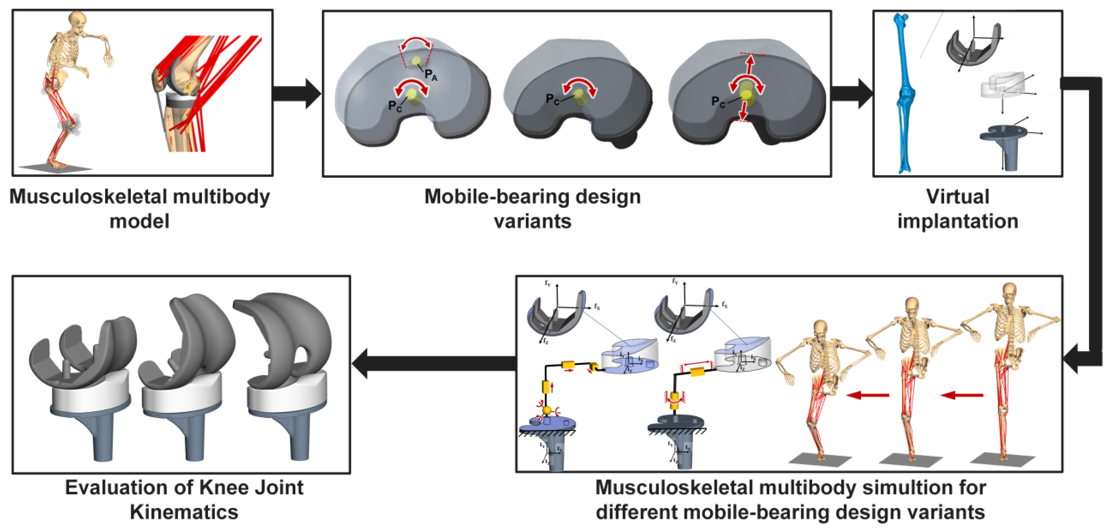
The multibody model of the lower extremity (Figure 2) consists of the pes, tibia, fibula, patella, pelvis, and torso, as well as the implant components. Specifically, the body weight (m = 66.7 kg) of the male subject (age = 88 years, height = 168 cm) with a neutral limb alignment was considered [41], and the mass of each body part was defined as a function of the patient’s body weight using regression equations [44]. The ligament structures were modeled as nonlinear springs using a mathematical model [45,46]. Muscles were modeled as active force elements, applying loads on the insertion and origin attachment sites. To calculate joint loads within the patellofemoral and tibiofemoral joint, a polygon contact model based on the elastic foundation theory was deployed [47]. This model was implemented computationally in SIMPACK (v9.7, Dassault Systèmes Deutschland GmbH, Gilching, Germany). To maintain a proper connection between the femoral component and the tibial insert, the tibial insert and the tibial tray, and the patellar component and the femoral component, a static equilibrium analysis was conducted in which the flexion angle of the knee joint was kept fixed.
Considering the established MB TKR design (Figure 3A, MB design variant I [13,18,43]) as the baseline design, we investigated two other MB design variants in order to reflect a broader range of currently available design principles on the market [13,18,43]. These modifications to the native manufacturer’s design were conducted because most MB knee implant designs from manufacturers are stand alone with only one design principle for the articulation between the tibial insert and the tibial tray, which makes the comparison between different MB designs difficult. For the analysis of the MB design variants, the native geometry (Figure 3A, MB design I) was imported into the software Creo Parametric (v6.0, Parametric Technology Corporation, Boston, MA, USA). To create the second design variant, the anterior pin and the guide groove were removed (Figure 3B, MB design II [13,18,43]). Compared to MB design I, the rotation of the insert is no longer limited by end stops. The MB design III enables a DoF movement of the tibial insert comprising a uniaxial rotation around the central pin PC and a translation along the surface of the tibial insert in the anterior-posterior direction [13,18,43]. For this purpose, we provided an elongated hole in the tibial insert (Figure 3C, mobile-bearing design III). This hole provides end stops to the translational motion, while the rotation is not limited by end stops.
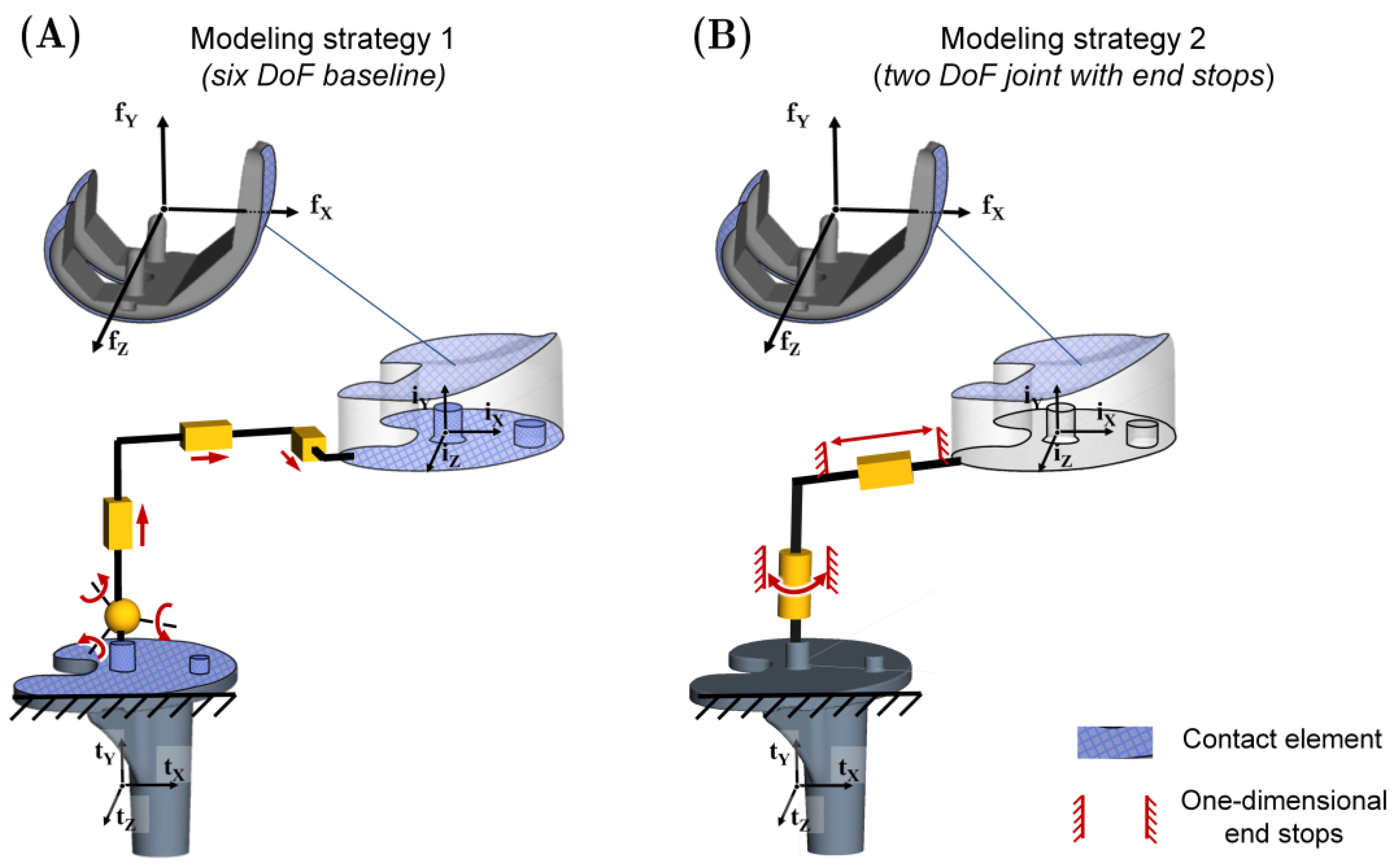
In order to compare the knee joint kinematics for the above-mentioned MB design variants during the squat motion, we deployed a six DoF joint between the tibial insert and tibial tray with a contact definition [47] between the 3D geometry of the tray and insert (Figure 4A). The design-specific mobility of the insert relative to the tray is completely modeled by the contact elements. Compliant contacts were also defined between the femoral and patellar component as well as the femoral component and tibial insert. The femoral component, tibial insert and tibial tray were assumed to be made of cobalt-chromium alloy (CoCr), ultra-high-molecular-weight polyethylene (UHMWPE), and titanium alloy (TiAlV), respectively. Similar to previous studies, the material properties regarding Young’s modulus (E) and Poisson’s ratio (ν) were as follows: ECoCr = 220 GPa and νCoCr = 0.3; EUHMWPE = 465 MPa and νUHMWPE = 0.45; and ETiAlV = 110 GPa and νTiAlV = 0.3 [24,37,41,48,49]. The surrounding bones were considered as rigid bodies and the interface between bone and implant components were fixed by zero DoF constraints.

2.2. Description of the Different Modeling Strategies to Consider Mobile-Bearing Total Knee Replacements

After the evaluation of the knee joint kinematics of the different MB design variants, we compared two different modeling strategies concerning the interface between the tibial insert and tibial tray with different kinematic joint topologies (Figure 4). Here it is worth mentioning that the terminology for the three MB design variants (MB design I, II, and III in Figure 3) should not be mixed up with the two modeling strategies 1 and 2 (Figure 4). In modeling strategy 1 (Figure 4A), the six DoF joint, as previously described, between insert and tray with a contact definition was used. This represents our baseline model (named six DoF baseline). Modeling strategy 2 comprises a two DoF joint consisting of a revolute and a prismatic joint (Figure 4B). It describes the rotation about the y-axis (superior-inferior translation iY) as well as the translation along the x-axis anterior-posterior translation iX). The translation is limited by end stops modeled by one-dimensional contact elements. This model can describe the MB design variant III. It can be used for MB design variant I by modeling rotational end stops, and for MB design variant II by setting the translational range of motion to zero. This modeling strategy is named as two DoF joint (Figure 4B).

3. Results

The resulting kinematic behavior of the TF joint was changed within the different MB design variants during the squat motion (Figure 5). The medio-lateral translation, femoral anterior-posterior translation, and tibiofemoral contact force showed almost no differences between MB design variants I and II. However, for MB design variant III, the kinematic pattern was considerably different compared to the other two MB design variants.
The peak femoral anterior-posterior translation value for all design variants occurred between flexion angles of 15°–30°. For design variant III, the peak value of 2.9 mm occurred at 18° knee flexion. The first two design variants (I and II) showed the peak value of 2.8 mm after 20°. Variants I and II showed a similar behavior concerning the femoral anterior-posterior translation (Figure 5A). However, variants I and II showed considerably less femoral anterior-posterior translation compared to variant III. For instance, during the squat motion, we detected a posterior translation of 12.6 mm (variant II), whereas variant III showed a posterior translation of 16.8 mm at 90° knee flexion. Furthermore, the paradoxical anterior translation of variant III ceased in an earlier flexion range. The pattern of the mediolateral translation was similar between variants I and II, but there were differences compared to variant III in which the amount of the mediolateral translation was higher (Figure 5B). Concerning the commercially available variant I with a rotation pin and end stops, the end stops affected the mechanically possible internal-external rotation of the tibial insert relative to the tibial tray (Figure 5C). In this regard, we detected a maximum difference by more than 5° compared to variants II and III. Design variants II and III showed the maximum value of external rotation at 13°. The resulting tibiofemoral contact force during the squat motion remained nearly unchanged between the three variants (Figure 5D). However, during early knee flexion (30°–40°), the tibiofemoral contact force increased by more than 250 N for design variant III.
Concerning the modeling strategies, compared to the six DoF baseline, the two DoF joint captured the kinematic pattern well in the case of all three MB design variants (Figure 6). The maximum deviations occurred mostly at the end of the squat motion. Only slight deviations were observed for the tibial insert rotation (Figure 6(CI–CIII)), e.g., for design variant III the deviation was less than 1° at 90° knee flexion. Most of the deviations in calculated kinematics for the different modeling strategies occurred after 50° flexion. However, for design variants I and II, the deviations also occurred during mid-flexion. As mentioned above, the amount of deviation for all investigated parameters was low. While the differences between the modeling strategies were minor, the computation time was remarkably decreased in the case of the two DoF joint model with translational end stops for all three MB model design variants (Figure 6(DI–DIII)). For design variants I, II, and III, the computation time decreased by 68% (167 min), 80% (307 min), and 82% (278 min), respectively, when using the two DoF joint modeling strategy compared to the six DoF baseline modeling strategy.

4. Discussion

In the present study, differences in knee joint kinematics for MB TKRs with different design variants were presented deploying a musculoskeletal multibody model of the lower right extremity during a squat motion. Regarding the selection of these designs from a surgeon’s point of view, it is important to understand the design-specific elements of MB TKR´s and the biomechanical behavior in terms of the knee joint parameters (femoral translation or internal-external rotation). In this context, the computational prediction of these knee joint parameters is useful [11,24,25,29,31]. We intended to show the feasibility to integrate diverse MB design variants into a musculoskeletal multibody model and to systematically analyze the effects of different MB design variants on knee joints kinematics and kinetics.
The results revealed differences in the kinematics of the knee joint for the various MB TKR design variants. Compared to the commercially available MB design variant I, the other design variants showed differences in terms of the tibial insert internal-external rotation. As expected, constraining the insert rotation mechanically by end stops is mandatory when a limited rotational range of motion is in demand. Although the tibial insert rotation was mechanically constrained by end stops, design variant I showed almost the identical femoral anterior-posterior translation compared to variant II. This leads to the assumption that the tibial insert internal-external rotation does not directly influence the femoral translation. In the case of the design variant III, according to the previous studies [8,9], a higher range of motion should be enabled due to a facilitated increased femoral rollback when a functioning posterior cruciate ligament remains, since the femoral component is sliding on the tibial insert. Our results revealed that this design variant (III) had more than 4 mm higher femoral posterior translation compared to the other MB design variants. Our data correspond well with previous studies [8,9]. During flexion, the femoral rollback is an important characteristic as it significantly affects patellofemoral and tibiofemoral contact forces [50]; therefore, it should not be neglected. Furthermore, the range of motion in terms of the medio-lateral translation was also higher.
TKR with MB design poses various challenges to computational modeling. For instance, one challenge is to generate a realistic and stable model with an appropriate representation of the additional articulating interface between the tibial insert and the tibial tray [51]. Previous studies revealed that there are different modeling strategies to consider MB TKR model design variants within the numerical models [6,11,21,24,25,29,30,52]. The most frequently used modeling strategy is a six DoF joint between the tibial insert and tray [11,24,25,29,34,35,52,53]. In this study, we proposed a new modeling strategy as a two DoF joint with one-dimensional end stops in both DoFs. During the squat motion, only slight differences were observed between the kinematics of the six DoF baseline and the two DoF joint, which could be a result of either the pure contact definitions between the tibial insert and tray or numerical effects in the interaction of the tibiofemoral contact [47]. This strategy is computationally more efficient compared to the six DoF baseline and is able to map the investigated MB design variants. On the one hand, our data showed the versatility of the six DoF modeling strategy, which can be applied to all currently available MB design variants. On the other hand, this strategy resulted in considerably more computation time compared to the proposed two DoF joint with end stops, which makes large-scale parameter studies less efficient. Therefore, the modeling strategy with six DoF baseline is the least favorable for multibody modeling. Additionally, for further preclinical testing, computational time is an important factor that should be considered. Previous studies [6,21,30,37] used revolute joints with/without contact to efficiently consider MB design variants. A modeling strategy as unrestricted rotation in the MB interface (like MB design variant II in our study) is possible and computationally efficient for such designs. However, it is not suitable for all available MB design variants, e.g., there is no possibility to consider multidirectional movements.
The current study did not aim to show superior results for FB or MB TKR designs. In future studies, the influence of design-specific parameters, e.g., the location of the axis of rotation of the rotating bearing [20], the position of the rotation pin with the presented simulation model, or intraoperative parameters such as the malrotation of the tibial component, should be analyzed. Our computational study shows some limitations. Firstly, one dataset was used for geometry derivation, which makes the results prone to patient individual factors as there are considerable differences in knee joint morphology, age, and weight of the patients, which all influence the results [54,55]. Therefore, the proposed results should be interpreted carefully. Based on a commercially available MB design, two additional design variants were created using computer-aided design modifications. A more efficient representation may be achieved by implementing MB TKR design variants, which are on the market. Furthermore, most MB implants from manufactures are stand alone with only one articulating design variant, which makes the comparison difficult. Thus, the investigation of inter-individual variability with several subjects and the assessment of different off-the-shelf MB designs are important topics for using the presented approach in future studies. However, our study represents fundamental work to analyze different MB design variants with an efficient modeling strategy (a two DoF joint with end stops) and the option to provide boundary conditions for finite element models taking into account the musculoskeletal system. Validation of the joint parameters on the kinematic and kinetic levels was also restricted due to the limited availability of open-source datasets [39,56] as they commonly used FB TKRs.

5. Conclusions

In our computational study, altered knee joint kinematics were observed depending on the MB design variant. The range of knee motion as the femoral anterior-posterior translation can be influenced by specific design elements, such as the presence of end stops. Our study, therefore, assists the biomechanical understanding of the analysis of MB total knee systems that is offered by different design variants. Furthermore, the present study identified if a two DoF joint modeling strategy is capable of generating reliable results for different MB design variants. Compared to the commonly used six DoF baseline strategy, this modeling strategy is more efficient since it requires contact definition only to limit the specific DoF, which seems to be mandatory to consider specific design elements (e.g., end stops) of MB TKR´s. We investigated the kinematics of three different total knee endoprostheses design variants to show the ability of the proposed musculoskeletal simulation framework for developing and virtually testing new design concepts of total knee endoprostheses. Our musculoskeletal multibody simulation framework can be employed for motions outside of the studied squat motion. It could be used to study, e.g., sport activities after TKR, which are commonly recommended [57,58,59,60].

Author Contributions

Conceptualization, M.K., C.W. and R.B.; methodology, M.K., I.S., S.K., C.W., T.M.G. and R.B.; software, M.K. and I.S.; data curation, M.K.; resources, R.B.; visualization, M.K., I.S., C.W. and R.B.; investigation, M.K., I.S., S.K., T.M.G., C.W. and R.B.; writing—original draft preparation, M.K.; writing—review and editing, I.S., S.K., T.M.G., C.W. and R.B.; supervision, T.M.G., C.W. and R.B. All authors have read and agreed to the published version of the manuscript.

Funding

This research received no external funding.

Institutional Review Board Statement

Not applicable.

Informed Consent Statement

Not applicable.

Data Availability Statement

The data presented in this study are available in the article.

Acknowledgments

Special thanks to Kurt Johnson (Department of Orthopaedics, Rostock University Medical Center, Rostock, Germany) for his help in drawing some of the figures and proofreading the manuscript.

Conflicts of Interest

Two of the authors (S.K. and T.M.G.) are employees of Aesculap AG Tuttlingen, a manufacturer of orthopedic implants. The role of the two authors (S.K. and T.M.G.) had no effect on the collection and processing of the data. There are no personal circumstances or interests that influenced the representation or interpretation of the reported results. The other authors (M.K., I.S., C.W. and R.B.) declare no conflict of interest.

References

  1. Anderson, J.G.; Wixson, R.L.; Tsai, D.; Stulberg, S.D.; Chang, R.W. Functional outcome and patient satisfaction in total knee patients over the age of 75. J. Arthroplast. 1996, 11, 831–840. [Google Scholar] [CrossRef]
  2. Bourne, R.B.; Chesworth, B.M.; Davis, A.M.; Mahomed, N.N.; Charron, K.D.J. Patient satisfaction after total knee arthroplasty: Who is satisfied and who is not? Clin. Orthop. Relat. Res. 2010, 468, 57–63. [Google Scholar] [CrossRef] [Green Version]
  3. Gibon, E.; Goodman, M.J.; Goodman, S.B. Patient Satisfaction After Total Knee Arthroplasty: A Realistic or Imaginary Goal? Orthop. Clin. N. Am. 2017, 48, 421–431. [Google Scholar] [CrossRef]
  4. Baker, P.N.; van der Meulen, J.H.; Lewsey, J.; Gregg, P.J. The role of pain and function in determining patient satisfaction after total knee replacement. Data from the National Joint Registry for England and Wales. J. Bone Jt. Surg. Br. 2007, 89, 893–900. [Google Scholar] [CrossRef]
  5. Mannion, A.F.; Kämpfen, S.; Munzinger, U.; Kramers-de Quervain, I. The role of patient expectations in predicting outcome after total knee arthroplasty. Arthritis Res. Ther. 2009, 11, R139. [Google Scholar] [CrossRef] [Green Version]
  6. Kessler, O.; Lacatusu, E.; Sommers, M.B.; Mayr, E.; Bottlang, M. Malrotation in total knee arthroplasty: Effect on tibial cortex strain captured by laser-based strain acquisition. Clin. Biomech. 2006, 21, 603–609. [Google Scholar] [CrossRef] [PubMed]
  7. Kobayashi, H.; Mitsugi, N.; Mochida, Y.; Taki, N.; Akamatsu, Y.; Aratake, M.; Ota, H.; Ishii, K.; Harigane, K.; Ideno, T.; et al. Mid- term results of stryker® scorpio plus mobile bearing total knee arthroplasty. Sports Med. Arthrosc. Rehabil. Ther. Technol. 2012, 4, 38. [Google Scholar] [CrossRef] [Green Version]
  8. Hwang, B.-H.; Lee, W.-S.; Park, K.-K.; Yang, I.-H.; Han, C.-D. Anterior-posterior glide mobile-bearing total knee arthroplasty: Complications related to prosthesis design. J. Arthroplast. 2011, 26, 1438–1444. [Google Scholar] [CrossRef] [PubMed]
  9. Kim, K.T.; Kang, M.S.; Lim, Y.H.; Park, J.W.; Wang, L. Short-Term Results of Total Knee Arthroplasty with Anterior-Posterior Glide LCS Mobile-Bearing System. Knee Surg. Relat. Res. 2014, 26, 162–167. [Google Scholar] [CrossRef] [PubMed] [Green Version]
  10. Yamazaki, T.; Futai, K.; Tomita, T.; Sato, Y.; Yoshikawa, H.; Tamura, S.; Sugamoto, K. 3D kinematics of mobile-bearing total knee arthroplasty using X-ray fluoroscopy. Int. J. Comput. Assist. Radiol. Surg. 2015, 10, 487–495. [Google Scholar] [CrossRef]
  11. Maas, A.; Kim, T.K.; Miehlke, R.K.; Hagen, T.; Grupp, T.M. Differences in anatomy and kinematics in Asian and Caucasian TKA patients: Influence on implant positioning and subsequent loading conditions in mobile bearing knees. BioMed Res. Int. 2014, 612838. [Google Scholar] [CrossRef]
  12. Huang, Z.-M.; Ouyang, G.-L.; Xiao, L.-B. Rotating-platform knee arthroplasty: A review and update. Orthop. Surg. 2011, 3, 224–228. [Google Scholar] [CrossRef] [PubMed]
  13. Vertullo, C.J.; Easley, M.E.; Scott, W.N.; Insall, J.N. Mobile bearings in primary knee arthroplasty. J. Am. Acad. Orthop. Surg. 2001, 9, 355–364. [Google Scholar] [CrossRef] [PubMed]
  14. Walker, P.S.; Komistek, R.D.; Barrett, D.S.; Anderson, D.; Dennis, D.A.; Sampson, M. Motion of a mobile bearing knee allowing translation and rotation. J. Arthroplast. 2002, 17, 11–19. [Google Scholar] [CrossRef]
  15. Chouteau, J.; Lerat, J.-L.; Testa, R.; Moyen, B.; Fessy, M.-H.; Banks, S.A. Mobile-bearing insert translational and rotational kinematics in a PCL-retaining total knee arthroplasty. Orthop. Traumatol. Surg. Res. 2009, 95, 254–259. [Google Scholar] [CrossRef] [Green Version]
  16. Munzinger, U.K.; Boldt, J.G. Mobile-Bearing Knee Prostheses. In European Surgical Orthopaedics and Traumatology; Bentley, G., Ed.; Springer: Berlin/Heidelberg, Germany, 2014. [Google Scholar]
  17. Jenny, J.-Y.; Saragaglia, D. No Detectable Polyethylene Wear 15 Years After Implantation of a Mobile-Bearing Total Knee Arthroplasty with Electron Beam-Irradiated Polyethylene. J. Arthroplast. 2019, 34, 1690–1694. [Google Scholar] [CrossRef]
  18. Mulcahy, H.; Chew, F.S. Current concepts in knee replacement: Complications. AJR Am. J. Roentgenol. 2014, 202, W76–W86. [Google Scholar] [CrossRef]
  19. Lee, D.-H.; Lee, D.-K.; Shin, Y.-S.; Han, S.-B. Mid-term outcomes of floating platform mobile-bearing total knee arthroplasty under navigational guidance with a minimum 4-year follow-up. J. Arthroplast. 2013, 28, 1801–1805. [Google Scholar] [CrossRef]
  20. Williams, J.L.; Gomaa, S.T. Kinematics of Rotating Platform Total Knee Replacements: Does the Position of the Rotating Platform Axis Matter? In Proceedings of the 3rd Frontiers in Biomedical Devices Conference, Imaging and Anatomic Interaction; Simulation and Testing, Irvine, CA, USA, 18–20 June 2008; pp. 15–16. [Google Scholar]
  21. Colwell, C.W.; Chen, P.C.; D’Lima, D. Extensor malalignment arising from femoral component malrotation in knee arthroplasty: Effect of rotating-bearing. Clin. Biomech. 2011, 26, 52–57. [Google Scholar] [CrossRef] [PubMed]
  22. Capella, M.; Dolfin, M.; Saccia, F. Mobile bearing and fixed bearing total knee arthroplasty. Ann. Transl. Med. 2016, 4, 127. [Google Scholar] [CrossRef] [Green Version]
  23. Hanusch, B.; Lou, T.N.; Warriner, G.; Hui, A.; Gregg, P. Functional outcome of PFC Sigma fixed and rotating-platform total knee arthroplasty. A prospective randomised controlled trial. Int. Orthop. 2010, 34, 349–354. [Google Scholar] [CrossRef] [Green Version]
  24. Koh, Y.-G.; Lee, J.-A.; Lee, H.-Y.; Suh, D.-S.; Kim, H.-J.; Kang, K.-T. Effect of sagittal femoral component alignment on biomechanics after mobile-bearing total knee arthroplasty. J. Orthop. Surg. Res. 2019, 14, 400. [Google Scholar] [CrossRef] [Green Version]
  25. Kang, K.-T.; Koh, Y.-G.; Son, J.; Kwon, O.-R.; Lee, J.-S.; Kwon, S.K. Comparison of Kinematics in Cruciate Retaining and Posterior Stabilized for Fixed and Rotating Platform Mobile-Bearing Total Knee Arthroplasty with respect to Different Posterior Tibial Slope. BioMed Res. Int. 2018, 5139074. [Google Scholar] [CrossRef] [Green Version]
  26. Futai, K.; Tomita, T.; Yamazaki, T.; Tamaki, M.; Yoshikawa, H.; Sugamoto, K. In vivo kinematics of mobile-bearing total knee arthroplasty during deep knee bending under weight-bearing conditions. Knee Surg. Sports Traumatol. Arthrosc. 2011, 19, 914–920. [Google Scholar] [CrossRef] [PubMed]
  27. Zhang, J.; Chen, Z.; Wang, L.; Li, D.; Jin, Z. A patient-specific wear prediction framework for an artificial knee joint with coupled musculoskeletal multibody-dynamics and finite element analysis. Tribol. Int. 2017, 109, 382–389. [Google Scholar] [CrossRef] [Green Version]
  28. Catani, F.; Benedetti, M.G.; Bianchi, L.; Marchionni, V.; Giannini, S.; Leardini, A. Muscle activity around the knee and gait performance in unicompartmental knee arthroplasty patients: A comparative study on fixed- and mobile-bearing designs. Knee Surg. Sports Traumatol. Arthrosc. 2012, 20, 1042–1048. [Google Scholar] [CrossRef] [PubMed]
  29. Müller, J.H.; Zakaria, T.; van der Merwe, W.; D’Angelo, F. Computational modelling of mobile bearing TKA anterior-posterior dislocation. Comput. Methods Biomech. Biomed. Engin. 2016, 19, 549–562. [Google Scholar] [CrossRef]
  30. Sharma, A.; Komistek, R.D.; Ranawat, C.S.; Dennis, D.A.; Mahfouz, M.R. In vivo contact pressures in total knee arthroplasty. J. Arthroplast. 2007, 22, 404–416. [Google Scholar] [CrossRef]
  31. Innocenti, B.; Pianigiani, S.; Labey, L.; Victor, J.; Bellemans, J. Contact forces in several TKA designs during squatting: A numerical sensitivity analysis. J. Biomech. 2011, 44, 1573–1581. [Google Scholar] [CrossRef]
  32. Wen, Y.; Liu, D.; Huang, Y.; Li, B. A meta-analysis of the fixed-bearing and mobile-bearing prostheses in total knee arthroplasty. Arch. Orthop. Trauma Surg. 2011, 131, 1341–1350. [Google Scholar] [CrossRef]
  33. McEwen, H.M.J.; Barnett, P.I.; Bell, C.J.; Farrar, R.; Auger, D.D.; Stone, M.H.; Fisher, J. The influence of design, materials and kinematics on the in vitro wear of total knee replacements. J. Biomech. 2005, 38, 357–365. [Google Scholar] [CrossRef] [PubMed]
  34. Zhu, G.-D.; Guo, W.-S.; Zhang, Q.-D.; Liu, Z.-H.; Cheng, L.-M. Finite Element Analysis of Mobile-bearing Unicompartmental Knee Arthroplasty: The Influence of Tibial Component Coronal Alignment. Chin. Med. J. 2015, 128, 2873–2878. [Google Scholar] [CrossRef]
  35. Anuar, M.A.M.; Todo, M.; Nagamine, R.; Hirokawa, S. Dynamic finite element analysis of mobile bearing type knee prosthesis under deep flexional motion. Sci. World J. 2014, 2014, 586921. [Google Scholar]
  36. Guess, T.M.; Thiagarajan, G.; Kia, M.; Mishra, M. A subject specific multibody model of the knee with menisci. Med. Eng. Phys. 2010, 32, 505–515. [Google Scholar] [CrossRef] [PubMed]
  37. Srinivas, G.R.; Deb, A.; Kumar, M.N. A study on polyethylene stresses in mobile-bearing and fixed-bearing total knee arthroplasty (TKA) using explicit finite element analysis. J. Long Term Eff. Med. Implants 2013, 23, 275–283. [Google Scholar] [CrossRef]
  38. Kebbach, M.; Darowski, M.; Krueger, S.; Schilling, C.; Grupp, T.M.; Bader, R.; Geier, A. Musculoskeletal Multibody Simulation Analysis on the Impact of Patellar Component Design and Positioning on Joint Dynamics after Unconstrained Total Knee Arthroplasty. Materials 2020, 13, 2365. [Google Scholar] [CrossRef]
  39. Fregly, B.J.; Besier, T.F.; Lloyd, D.G.; Delp, S.L.; Banks, S.A.; Pandy, M.G.; D’Lima, D.D. Grand challenge competition to predict in vivo knee loads. J. Orthop. Res. 2012, 30, 503–513. [Google Scholar] [CrossRef] [Green Version]
  40. Carbone, V.; Fluit, R.; Pellikaan, P.; van der Krogt, M.M.; Janssen, D.; Damsgaard, M.; Vigneron, L.; Feilkas, T.; Koopman, H.F.J.M.; Verdonschot, N. TLEM 2.0—A comprehensive musculoskeletal geometry dataset for subject-specific modeling of lower extremity. J. Biomech. 2015, 48, 734–741. [Google Scholar] [CrossRef] [Green Version]
  41. Thelen, D.G.; Won Choi, K.; Schmitz, A.M. Co-simulation of neuromuscular dynamics and knee mechanics during human walking. J. Biomech. Eng. 2014, 136, 021033. [Google Scholar] [CrossRef]
  42. Lampe, F.; Sufi-Siavach, A.; Bohlen, K.E.; Hille, E.; Dries, S.P.M. One year after navigated total knee replacement, no clinically relevant difference found between fixed bearing and mobile bearing knee replacement in a double-blind randomized controlled trial. Open Orthop. J. 2011, 5, 201–208. [Google Scholar] [CrossRef]
  43. Walker, P.S.; Sathasivam, S. Design forms of total knee replacement. Proc. Inst. Mech. Eng. Part H 2000, 214, 101–119. [Google Scholar] [CrossRef] [PubMed]
  44. Winter, D.A. Biomechanics and Motor Control of Human Movement, 4th ed.; Wiley: Hoboken, NJ, USA, 2009. [Google Scholar]
  45. Blankevoort, L.; Kuiper, J.H.; Huiskes, R.; Grootenboer, H.J. Articular contact in a three-dimensional model of the knee. J. Biomech. 1991, 24, 1019–1031. [Google Scholar] [CrossRef] [Green Version]
  46. Wismans, J.; Veldpaus, F.; Janssen, J.; Huson, A.; Struben, P. A three-dimensional mathematical model of the knee-joint. J. Biomech. 1980, 13, 677–685. [Google Scholar] [CrossRef] [Green Version]
  47. Hippmann, G. An Algorithm for Compliant Contact Between Complexly Shaped Bodies. Multibody Syst. Dyn. 2004, 12, 345–362. [Google Scholar] [CrossRef]
  48. Golish, S.R.; Mihalko, W.M. Principles of biomechanics and biomaterials in orthopaedic surgery. J. Bone Jt. Surg. Am. 2011, 93, 207–212. [Google Scholar] [CrossRef]
  49. Kurt, S.M. UHMWPE Biomaterials Handbook; Elsevier: Amsterdam, The Netherlands, 2016. [Google Scholar]
  50. Shoifi Abubakar, M.; Nakamura, S.; Kuriyama, S.; Ito, H.; Ishikawa, M.; Furu, M.; Tanaka, Y.; Matsuda, S. Influence of Posterior Cruciate Ligament Tension on Knee Kinematics and Kinetics. J. Knee Surg. 2016, 29, 684–689. [Google Scholar] [CrossRef]
  51. Morra, E.A.; Heim, C.S.; Greenwald, A.S. Preclinical computational models: Predictors of tibial insert damage patterns in total knee arthroplasty: AAOS exhibit selection. J. Bone Jt. Surg. Am. 2012, 94, e137. [Google Scholar] [CrossRef]
  52. Kwon, O.-R.; Kang, K.-T.; Son, J.; Kwon, S.-K.; Jo, S.-B.; Suh, D.-S.; Choi, Y.-J.; Kim, H.-J.; Koh, Y.-G. Biomechanical comparison of fixed- and mobile-bearing for unicomparmental knee arthroplasty using finite element analysis. J. Orthop. Res. 2014, 32, 338–345. [Google Scholar] [CrossRef]
  53. Zhang, J.-Y.; Wang, J.; Tian, D.-M.; Jiang, D.-P.; Li, J.-J.; Hu, Y.-C. Spherical center and rotating platform hinged knee prosthesis: Finite-element model establishment, verification and contact analysis. Knee 2020, 27, 731–739. [Google Scholar] [CrossRef]
  54. Kim, T.K.; Phillips, M.; Bhandari, M.; Watson, J.; Malhotra, R. What Differences in Morphologic Features of the Knee Exist Among Patients of Various Races? A Systematic Review. Clin. Orthop. Relat. Res. 2017, 475, 170–182. [Google Scholar] [CrossRef] [Green Version]
  55. Mahfouz, M.; Abdel Fatah, E.E.; Bowers, L.S.; Scuderi, G. Three-dimensional morphology of the knee reveals ethnic differences. Clin. Orthop. Relat. Res. 2012, 470, 172–185. [Google Scholar] [CrossRef] [PubMed] [Green Version]
  56. Kutzner, I.; Heinlein, B.; Graichen, F.; Bender, A.; Rohlmann, A.; Halder, A.; Beier, A.; Bergmann, G. Loading of the knee joint during activities of daily living measured in vivo in five subjects. J. Biomech. 2010, 43, 2164–2173. [Google Scholar] [CrossRef]
  57. Witjes, S.; Gouttebarge, V.; Kuijer, P.P.F.M.; van Geenen, R.C.I.; Poolman, R.W.; Kerkhoffs, G.M.M.J. Return to Sports and Physical Activity After Total and Unicondylar Knee Arthroplasty: A Systematic Review and Meta-Analysis. Sports Med. 2016, 46, 269–292. [Google Scholar] [CrossRef] [PubMed] [Green Version]
  58. Mündermann, A.; Dyrby, C.O.; D’Lima, D.D.; Colwell, C.W.; Andriacchi, T.P. In vivo knee loading characteristics during activities of daily living as measured by an instrumented total knee replacement. J. Orthop. Res. 2008, 26, 1167–1172. [Google Scholar] [CrossRef]
  59. Vitalis, L.; Russu, O.; Zuh, S.; Pop, T.S. Recommendations for Sport and Physical Activity after total Hip and Knee Arthroplasty: A Systematic Review. Acta Med. Transilv. 2021, 26, 63–66. [Google Scholar] [CrossRef]
  60. Shabani, B.; Bytyqi, D.; Batailler, C.; Servien, E.; Lustig, S. Sports After Knee Arthroplasty. In The Sports Medicine Physician; Piedade, S.R., Imhoff, A.B., Clatworthy, M., Cohen, M., Espregueira-Mendes, J., Eds.; Springer: Cham, Switzerland, 2019. [Google Scholar]
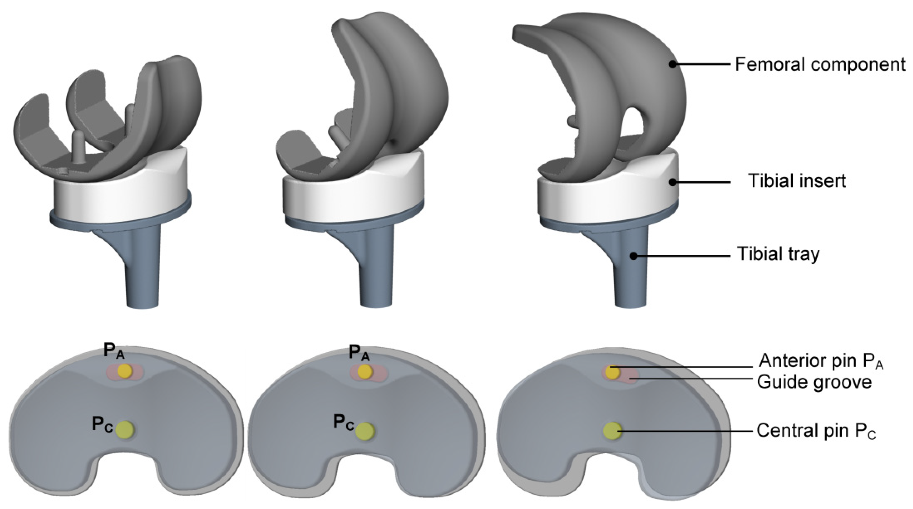
Figure 1. Exemplary movement of the commercially available mobile-bearing total knee replacement design (Columbus® uniaxially rotating platform total knee replacement) during the squat motion.
Applsci 12 00182 g001
Figure 2. Illustration of the procedure to analyze different mobile-bearing design variants. Using a musculoskeletal multibody model of the lower right extremity, we implemented different mobile-bearing design variants within virtual implantation. These designs were analyzed within a dynamic musculoskeletal multibody simulation during the squat motion to evaluate the knee joint kinematics.
Applsci 12 00182 g002
Figure 3. Mobile-bearing (MB) total knee replacement design variants investigated in this study. Baseline MB design variant I (A) is the commercially available design (Columbus® uniaxial rotating platform total knee replacement) with the central pin PC defining the axis of rotation and the anteriorly positioned pin PA limiting the range of rotation. In MB design variant II (B), the anterior pin PA was removed. In MB design variant III (C), the tibial insert has two degrees-of-freedom relative to the tray with a rotation around the central pin PC and an anterior-posterior translation along the elongated hole in the tibial insert.
Applsci 12 00182 g003
Figure 4. The interface between the tibial insert and the tibial tray of mobile-bearing (MB) design variants was modeled using two different modeling strategies. Exemplarily representation of the implant components and the coordinate systems for the femoral component f, tibial insert i, and tibial tray t. Depiction of the modeling strategy 1 (A) and 2 (B) as well as the corresponding degrees-of-freedom (DoF) between the tibial insert and tibial tray for the three MB design variants.
Applsci 12 00182 g004
Figure 5. Tibiofemoral kinematics and kinetics during the dynamic squat motion for the three mobile-bearing (MB) total knee replacements (MB design variants I, II, and III). Evaluation of the femoral anterior(+)-posterior(−) translation (A), tibial medio(−)-lateral(+) translation (B), tibial insert rotation with respect to the tibial tray (C), and tibiofemoral contact force (D).
Applsci 12 00182 g005
Figure 6. Tibiofemoral kinematics during the dynamic squat motion for the three mobile-bearing design variants I–III in case of two modeling strategies with different joint topologies (first: six DoF baseline; second: two DoF joint). Evaluation of the femoral anterior(+)-posterior(−) translation (AIAIII), tibial medio()-lateral(+) translation (BIBIII), and tibial insert rotation with respect to the tibial tray (CICIII). Furthermore, the computation time of the modeling strategies 1 and 2 was compared for the different mobile-bearing design variants (DIDIII).
Applsci 12 00182 g006
Publisher’s Note: MDPI stays neutral with regard to jurisdictional claims in published maps and institutional affiliations.