Article

Vertical Seismic Isolation Device for Three-Dimensional Seismic Isolation of Nuclear Power Plant Equipment—Case Study

1
Korea Atomic Energy Research Institute, Daejeon 34057, Korea
2
SMARTEK E&C, Daejeon 34013, Korea
3
School of Mechanical, Automotive and Aeronautical Engineering, Korea National University of Transportation, Chungju 27469, Korea
4
Nuclear Power Team & Structural Group, Korea Electric Association, Seoul 05718, Korea
*
Author to whom correspondence should be addressed.
Appl. Sci. 2022, 12(1), 320; https://doi.org/10.3390/app12010320
Submission received: 24 November 2021 / Revised: 24 December 2021 / Accepted: 24 December 2021 / Published: 29 December 2021
(This article belongs to the Special Issue Efficient Damping and Isolation Systems for Civil Structures)

Abstract

:
The purpose of this study was to develop a vertical seismic isolation device essential for the three-dimensional seismic isolation design of nuclear power plant equipment. The vertical seismic isolation device in this study has a concept that can be integrally combined with a conventional laminated rubber bearing, a horizontal seismic isolator with a design vertical load of 10 kN. To develop the vertical seismic isolation device, the vertical spring and the seismic energy dissipation device capable of limiting the vertical displacement of the spring were designed and their performances were verified through actual tests. In this study, the target elevation of the floor is 136 ft, where safety-related nuclear equipment, such as cabinet and remote shutdown console, etc., is installed. The sensitivity studies were carried out to investigate the optimal design vertical isolation frequencies for the target building elevation. Based on the results of the sensitivity study, a disc spring and a helical coil spring were selected for the vertical stiffness design, and the steel damper was selected for the seismic energy dissipation, and their performance characteristics were tested to confirm the design performance. For the steel damper, three types were designed and their energy dissipation characteristics by hysteretic behavior were confirmed by the inelastic finite element analyses and the tests in static fully reversed cyclic conditions. Through the study of the vertical seismic isolation device, it was found that 2.5 Hz~3.0 Hz is appropriate for the optimal design vertical isolation. With results of the vertical seismic isolation performance analysis, the appropriate number of steel dampers are proposed to limit the vertical seismic displacement of the spring within the static displacement range by the design vertical load.

1. Introduction

After the Fukushima nuclear power plant accident, nuclear power plant safety improvement against earthquakes has emerged as a major issue. The current Safe Shutdown Earthquake (SSE) design basis required for nuclear power plant design is 0.3 g, which is 50% higher than the previous 0.2 g. In recent years, seismic design requirements are being strengthened to ensure the seismic safety of nuclear power plants in case of beyond-design-basis earthquakes, and various methods are being studied to solve this issue [1,2,3].
In general, it is true that the improvement of seismic capacity of nuclear power plants has been mainly focused on plant buildings and structures. To achieve this goal, the seismic base isolation design technology using laminated rubber bearings (LRBs) has been studied worldwide for a long time as one of the measures to ensure the safety of nuclear power plants against large earthquake loads. In the development of seismic isolation design technology for nuclear power plant application, the entire major nuclear power plant buildings are constructed on one common mat, and this is supported by seismic isolators. Most of the future advanced nuclear power plants currently under development adopt seismic isolation design for nuclear power plant buildings [4,5,6].
So far, the development of seismic isolation design technology for nuclear power plant buildings has been mainly focused on LRBs that can support the heavy building weight stably and allow horizontally flexible deformation. These LRBs have been continuously developed as a seismic isolator only for horizontal seismic isolation of nuclear power plant buildings because the horizontal design earthquake level is much larger than the vertical design level. Recently, the vertical seismic design load is required to be equal to the horizontal load level. Therefore, the unavoidable disadvantage of the LRBs amplifying the vertical earthquake response by vertical earthquakes is a big issue to overcome [7,8,9]. In particular, as the vertical seismic load level has recently increased and the importance of nuclear power plant design covering this has become more of an issue, horizontal seismic isolation design using only LRBs may not be able to ensure the required seismic design goal.
To overcome the disadvantage of the horizontal seismic isolation with the LRBs, much research and development on three-dimensional (3D) seismic isolators has been carried out worldwide [10,11,12,13,14,15]. However, there are still not many practical cases applied to nuclear power plants. One of the design barriers of vertical seismic isolation for whole reactor buildings may be to construct a rigid upper mat supporting the reactor buildings to prevent local uneven settlement due to the flexibility of the vertical seismic isolation device.
The goal of this study is to develop a 3D seismic isolator for individual nuclear power plant facilities that are relatively easy to install and maintain when compared with the whole building seismic isolation design. For this purpose, a study was conducted on a vertical seismic isolation device having a spring and a steel damper that can be integrally combined with lead-inserted small LRBs for horizontal seismic isolation developed for individual facilities in nuclear power plants [16,17].
There are many studies for the supplemental seismic energy dissipation using the LRBs, such as ring-type steel [18], high damping rubber [19], friction pad [20], and viscous damper [21]. In this study, various dimensions and shapes of thin plate-type steel dampers integrated with the LRBs are investigated, and the capacity of their seismic energy dissipation is verified by the tests and simulations.
A disc spring or a helical coil spring was used for the vertical stiffness design that determines the vertical seismic isolation frequency (VIF) of the vertical seismic isolation device, and a steel damper was used for the vertical seismic energy dissipation that controls the vertical relative displacement. In this study, with the goal of 3D seismic isolation design for nuclear power plant facilities installed in 136 ft of an actual nuclear power plant building, a vertical spring design for determining the optimal VIF and an optimal steel damper that can accommodate relative vertical displacement were designed and verified. The feasibility of the design concept was confirmed by performing verification tests and simulations for spring and steel damper.

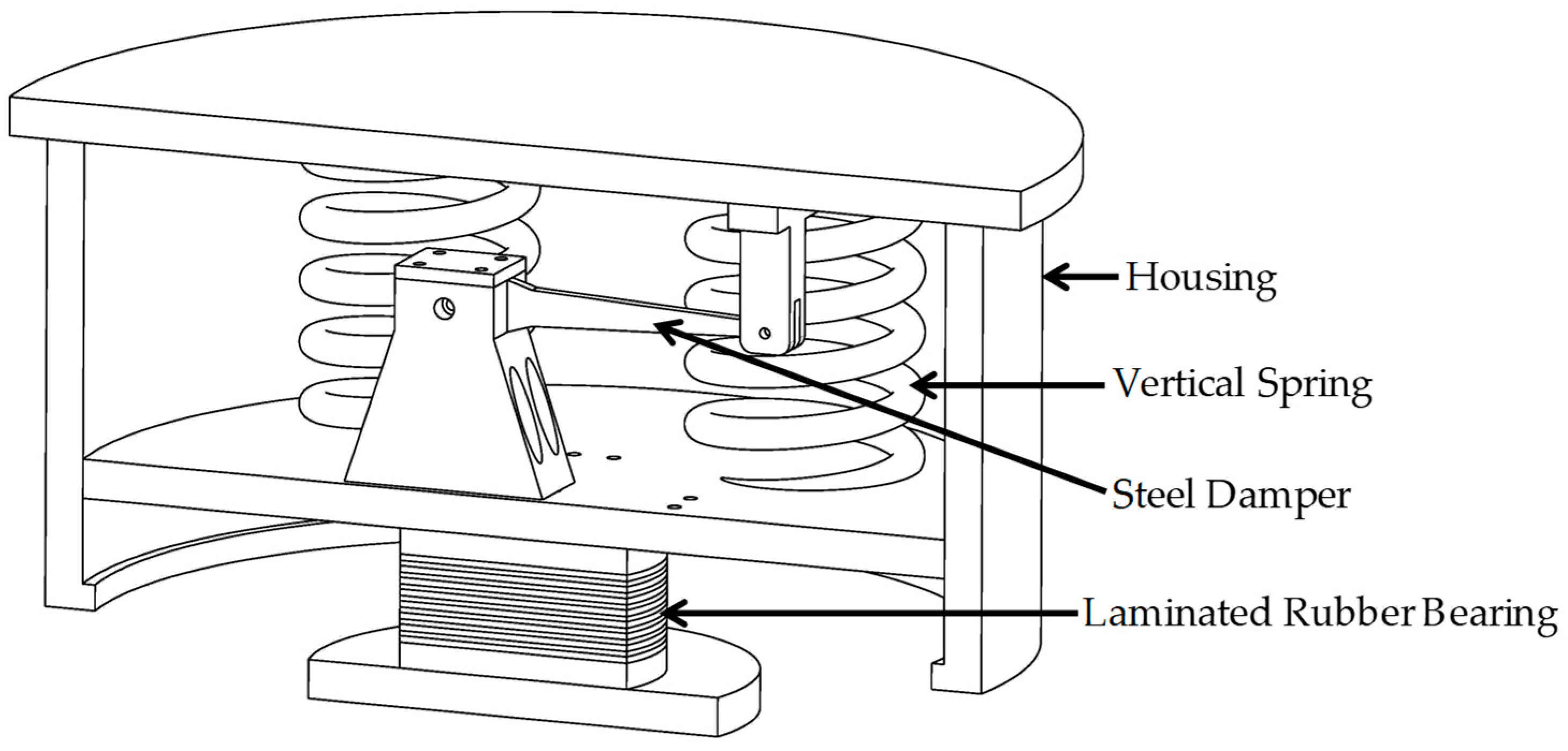
2. Concept of Vertical Seismic Isolation Device

2.1. Configurations and Dimensions

The 3D seismic isolator being developed in this study is intended to be applied to individual facilities of nuclear power plants where severe vertical earthquake response amplification is expected. To this end, the horizontal seismic isolator uses a lead-inserted small LRB with proven stability and seismic isolation performance [16,17], and a spring-damper-based vertical seismic isolator is mounted on the top of the LRB.
Figure 1 presents the conceptual configuration of the horizontal–vertical integrated 3D seismic isolator being developed in this study. As shown in the figure, the LRB with relatively high vertical stiffness supports vertical springs and dampers of the vertical seismic isolation device.
The housing in Figure 1 has a function to transmit the horizontal seismic load, simultaneously guiding the vertical seismic motion of the spring due to the superstructure. Table 1 shows the specifications of the 3D seismic isolator based on the lead-inserted LRB used in this study.
As shown in Table 1, the design vertical load of the 3D seismic isolator considered in this study is 10 kN, the total height of the LRB is 34 mm, and the design horizontal seismic frequency is 2.3 Hz. The vertical seismic isolation device mounted on the top of the LRB will maintain the vertical stiffness by a disc spring or a helical spring and dissipate the vertical seismic energy by steel dampers.
In the design of the vertical seismic isolation device, the vertical spring mainly controls the VIF, and the vertical damper controls the vertical displacement of the spring. The higher the vertical stiffness, the higher the vertical seismic isolation frequency, and the lower the vertical seismic isolation performance. The lower the vertical stiffness, the better the vertical seismic isolation performance, but the displacement of the vertical spring will significantly increase so that it may not meet the design concept of integral 3D seismic isolator presented in Figure 1. Therefore, a vertical spring design having an appropriate design VIF and a damping device design capable of properly suppressing the vertical spring displacement are required in a design stage.

2.2. Vertical Design Displacement Limit

Figure 2 presents the operation concept of the 3D seismic isolator. Figure 2b shows the schematics of static vertical displacement condition due to dead weight of the super structure, and Figure 2c shows the horizontal and vertical displacement condition during earthquake events. The housing of the vertical seismic isolator transmits the horizontal load of the superstructure to the LRB and guides the vertical seismic movement. The dimension design of such a housing is determined according to the shape and dimensions of the vertical spring and steel dampers, which are determined according to the determination of the design VIF. The most important aspect in this design concept is that the housing should be designed so that interference with the LRB does not occur during the beyond-design-basis earthquakes. To do this, the vertical seismic displacement of the spring should be properly limited by the determination of a design VIF and damper design.
In this paper, the design target is established to limit the maximum vertical seismic displacement response within the static displacement of the spring by design vertical load of 10 kN. This will prevent detachment between the housing and the vertical spring.
Table 2 presents the required vertical stiffness of the spring according to the design VIF for a design vertical load of 10 kN and their static vertical displacement values.

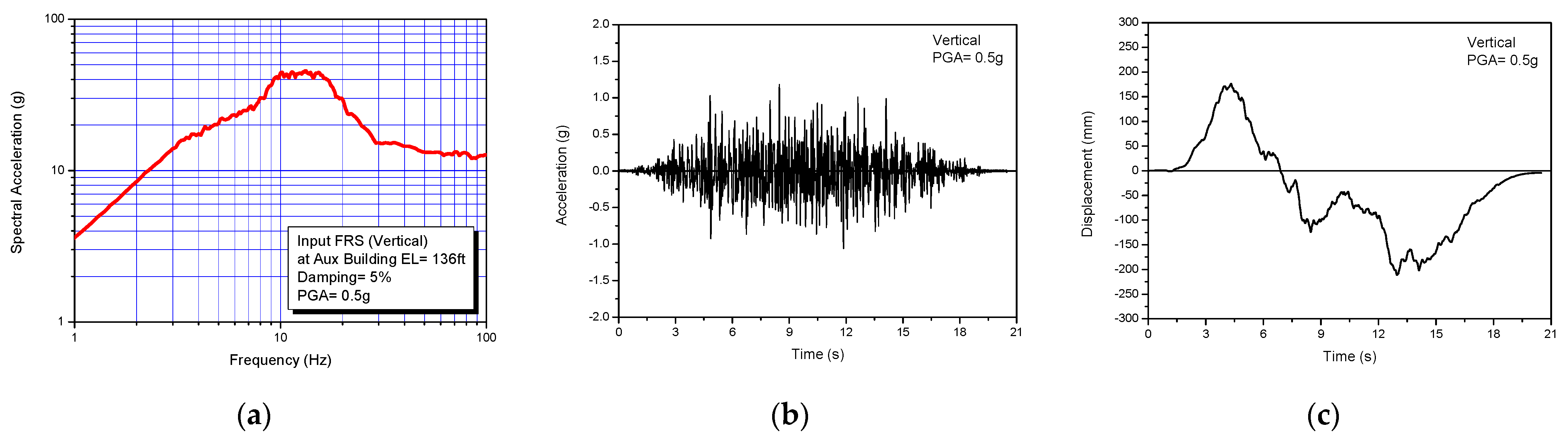
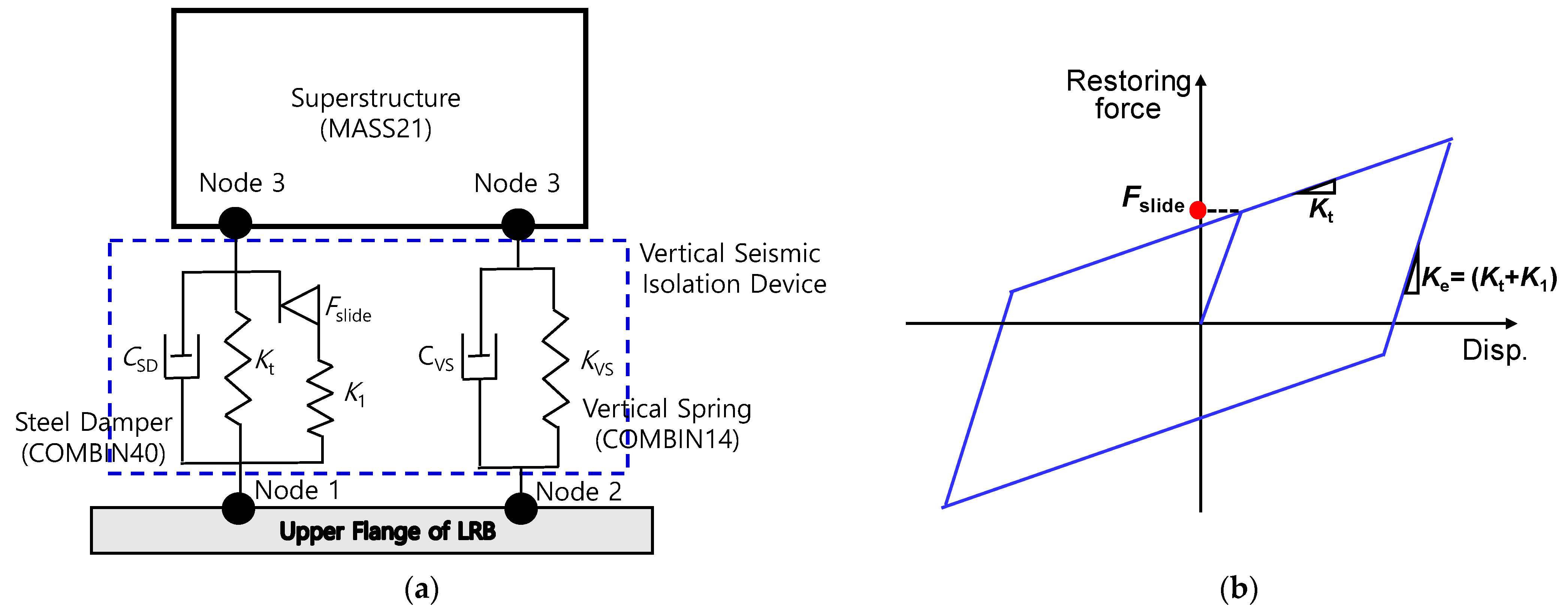
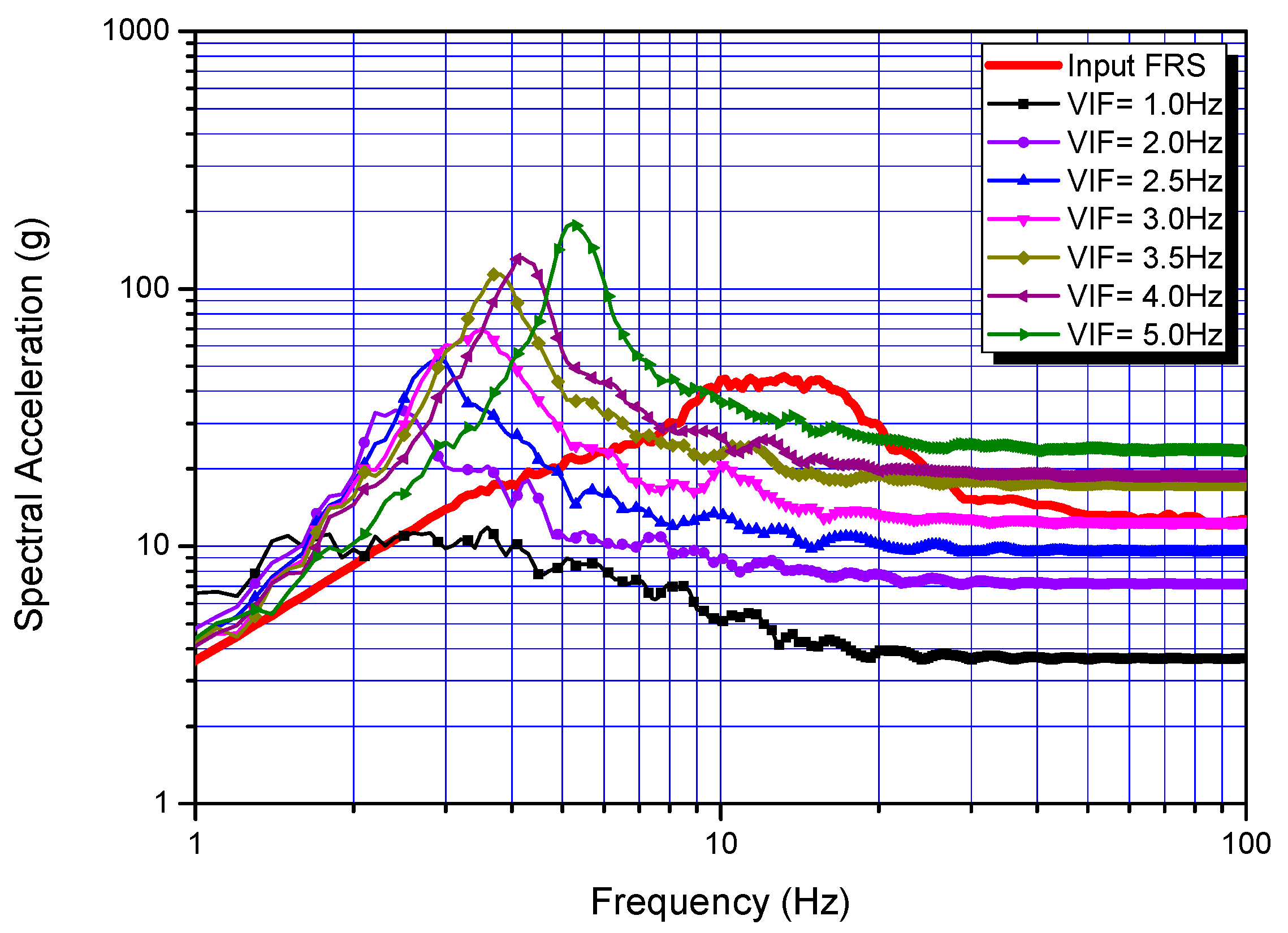
3. Sensitivity Study on Vertical Seismic Isolation Performance with VIF

In principle, the basic concept of seismic isolation design is to design an appropriate seismic isolation frequency to avoid resonance with input earthquakes by moving the natural frequency of the superstructure in the frequency range of a strong earthquake to a sufficiently low frequency using a seismic isolator.
In general, the vertical natural frequency of a nuclear power plant building is around 10~20 Hz, which is out of the range of peak spectral frequency band, 3 Hz to 10 Hz in the US NRC RG-1.60 design ground-response spectrum [22]. However, there is possibility of resonance seismic response if the earthquake level increases enough to invoke severe cracks in the nuclear power plant building structures. In this case, the spectral peak frequencies of the response spectrum at the floor where the nuclear power plant equipment is seismically isolated may be shifted to a lower region due to the decrease of the structural stiffness of the nuclear power plant building. This situation can cause severe vertical seismic response amplification in nuclear power plants. Therefore, in the vertical seismic isolation design of nuclear power plants against a large earthquake, it is very important to determine the design VIF that can deviate from the floor-response spectrum peak frequency band and the resonant frequency of the upper structure.
In this study, a remote shutdown console (RSC), which is installed at elevation of 136 ft of an actual nuclear power plant building, is chosen as one of the target 3D seismic isolation equipment. To investigate the sensitivity of the VIF, the vertical seismic isolation performance analyses are carried out with the preliminary specified design parameters of the vertical seismic isolation device, as shown in Table 3.
Figure 3 presents the input earthquake used in the design of the vertical seismic isolation device in this study. Figure 3a is the vertical floor-response spectrum at 136 ft of the auxiliary building, corresponding to the peak ground acceleration, PGA = 0.5 g, which is 1.67 times the Safe Shutdown Earthquake (PGA = 0.3 g). We can see that the peak spectral frequency band exists at 10 Hz to 16 Hz and the peak spectral acceleration is large at about 40 g. As shown in Figure 3b,c, the zero-period acceleration (ZPA) value is 1.2 g, and the peak/valley displacements are −211 mm/+176 mm.
Figure 4 presents the simple seismic analysis model used for the sensitivity of the vertical seismic isolation performance on the VIF. For the transient seismic time history analysis, a commercial finite element program ANSYS [23] was used. As shown in Figure 4a, the vertical spring is modeled by a simple stiffness–damping element (COMBIN14), and the vertical damper is model with a bilinear force–displacement element (COMBIN40), reflecting the hysteretic characteristics of the steel damper. It was assumed that the inertia mass of the superstructure acts as a concentrated mass (MASS21) at node 3. Figure 4b shows the concept of the bilinear model of the steel damper.
To investigate the sensitivity of the design VIF on the vertical seismic isolation performance, the design VIF was considered in the range of 1 Hz~5 Hz. The equivalent damping ratio and stiffness of the steel damper corresponding to the hysteretic bilinear model in Table 3 are 30.7% and 75,291 N/m, respectively. The equivalent stiffness of the steel damper has a corresponding natural frequency of about 1.38 HZ for a vertical design load of 10 kN. Therefore, the actual VIF will be determined by considering both spring and steel damper stiffness.
Figure 5 shows the result of the calculated vertical response spectrum for the super structure according to the design VIF determined by the stiffness value of the vertical spring. As shown in the figure, it can be seen that the lower the design VIF, the higher the seismic isolation performance is due to the frequency shift effect. When the design VIF is 1.0 Hz, the spectral acceleration response of the superstructure is significantly reduced compared with the input response spectrum throughout frequencies. When the design VIF increases to 3 Hz, the superstructure exhibits the vertical seismic isolation effect in the range of about 6 Hz to 50 Hz, and the ZPA value is almost similar to that of the input earthquake without vertical seismic isolation effect. When the design VIF exceeds 3.0 Hz, the vertical seismic isolation effect is greatly reduced in the overall frequency range, and the ZPA value of the superstructure becomes larger than that of the input earthquake.
Figure 6 shows the maximum vertical spring displacement response according to the design VIF. As shown in Figure 6a, when only a vertical spring is used without using a steel damper, the vertical spring displacement becomes very large (e.g., 101.3 mm when VIF = 3 Hz). Therefore, it is not possible to design a vertical seismic isolation device actually accommodating the LRB dimensions in Table 1. When the steel damper with the design characteristics of Table 3 is used, the vertical spring displacement can be significantly reduced to 30 mm or less, as shown in Figure 6b.
Table 4 summarizes the sensitivity analysis results of the vertical seismic isolation performance according to the design VIF. As shown in the table, it can be seen that as the design VIF increases, the effective frequency range in which the actual seismic isolation effect can be obtained is rapidly reduced. When the design VIF is equal to or higher than 3.0 Hz, the ZPA response becomes larger than that of the input floor response spectrum, and then the vertical seismic isolator has the opposite effect of amplifying the vertical seismic response in the high-frequency region.
In addition, it can be seen that the actual VIF is larger than the design value assumed for the vertical stiffness spring due to the stiffness effect of the steel damper, showing the hysteretic characteristic. The lower the design VIF, the larger the stiffness effect of the steel damper. When the design VIF is 1.0 Hz, the actual VIF increases by 80%.

4. Vertical Spring Design for Vertical Seismic Isolation Device

As shown in Figure 1 above, the spring for vertical stiffness is designed to be applied to a vertical seismic isolator that can be integrally mounted on a small-sized LRB with a vertical design load of 10 kN, which is a horizontal seismic isolator for individual facilities in a nuclear power plant. To substantiate the stiffness of the vertical seismic isolation device, the spring design was investigated in detail based on the sensitivity analysis results above.
In this study, two types, such as disc spring and helical coil spring, were chosen for a stiffness design of the vertical seismic isolation device.

4.1. Disc Spring Design

The disc spring used in this study is a cone-shaped, thin steel structure with outer diameter (D), inner diameter (d), thickness (t), and height (H) as shown in Figure 7. When a vertical force is applied, the disc spring stably undergoes compression deformation and has a constant stiffness value within the operating displacement. Once the design stiffness value is determined, it can be designed to have the appropriate load capacity and displacement range by stacking the required number of disc springs in series or in parallel.
The relationship between the applied load (F) and the corresponding displacement (y) in the disc spring in Figure 7 can be described as the following equation [24]:
F = 2 E t ( 1 ν 2 ) Z D 2 [ y 3 3 h y 2 + 2 y ( h 2 t 2 ) ]    
where
Z = 1 π ( C 1 C ) 2 [ ( C + 1 C 1 ) ln 2 C ] 1
C = D d    
In the above equation, E and ν represent the elastic modulus and Poisson’s ratio of the material, respectively. When the disc springs are stacked in series, the total displacement and equivalent stiffness are proportional to 1/n (n is number of disc springs). Therefore, when the design VIF is determined, it can be implemented by connecting an appropriate number of disc springs in series.
Table 5 presents the design parameters of the disc spring designed in this study. The plate spring material used in the design is JIS SUP10 spring steel.
In Table 5 above, the shut displacement (h) refers to the maximum displacement that the disc spring can accommodate. The disc spring is mounted on the upper flange of LRB, which functions as a horizontal seismic isolator. If the outer diameter of the disc spring is larger than the outer diameter of the LRB, bending deformation may occur in the upper flange of LRB due to the load reaction force applied to the disc spring by the seismic response of the superstructure. In this study, considering the outer diameter of 100 mm of the LRB, the outer diameter of the disc spring is determined to be 80 mm.
In general, the design-allowable displacement of the disc spring assumes 75% of the shut displacement. In this case, the design-allowable displacement for a single disc spring of Table 5 is 1.65 mm, considering the shut displacement (h = 2.2 mm). Therefore, assuming that the relationship between displacement and reaction force is linear within the design-allowable displacement of the single disc spring, the load capacity of the single disc spring becomes 22.9 kN from Equation (1) above, and, accordingly, the spring stiffness is determined to be 13,879 kN/m.
Figure 8 compares the stiffness test results for six single disc springs manufactured according to the design parameters in Table 5 and the stiffness values calculated from Equation (1). As shown in the figure, it was confirmed that the stiffness test results and calculation results were well matched up to the design-allowable displacement of 1.65 mm, and linearity was guaranteed.
Table 6 presents the results of design summary for the set of disc spring that satisfies the design VIF. As shown in the table, when the design VIF is lower, the required number of disc springs greatly increases. This results in a significant increase in the total height of the spring and acts as a burden in the housing design. When the design VIF is set to 2.0 Hz or less, the required housing height of the vertical seismic isolation device is more than 500 mm. Therefore, when using a disc spring, it is desirable to determine the design VIF at least larger than 2.5 Hz with consideration of an appropriate height.

4.2. Helical Coil Spring Design

In this study, a helical coil spring, which is widely used in industry, was selected as another spring type to provide vertical stiffness. The main design variables that determine the stiffness characteristics of a helical coil spring are the coil diameter, section diameter, and number of turns, as shown in Figure 9.
In above figure, Lf and La indicate the free length and assembled length with compression force, respectively.
The relationship between the applied force (F) and the total stretch (y) of a helical coil spring in Figure 9 can be approximately described as follows [24]:
y = F ( 8 D 3 N a ) d 4 G
where D, d, Na, and G represent the helical coil diameter measured from spring axis to center of section, diameter of circular section, number of active turns, and shear modulus of the material, respectively.
As the helical coil spring has relatively less rigidity than the disc spring, it is recommended to install the springs in parallel. In this study, four helical coil springs, which have a spring diameter D = 88 mm and coil section diameter d = 12 mm, are considered for a vertical stiffness design corresponding to vertical design load of 10 kN.
Table 7 presents the results of design summary for the set of helical coil springs that satisfies the design VIF.
As shown in the above table, as the design VIF decreases, the number of coil turns required for the spring stiffness increases rapidly, which leads to a great increase in the total height of the spring. In this study, the design VIF of 2.5 Hz~3.0 Hz was selected to be an appropriate total height of the helical coil spring for substantiation of the design.
Table 8 shows the detailed design parameter values for the helical coil spring that satisfies the selected design VIF of 2.5 Hz and 3.0 Hz.
To substantiate the actual stiffness design of the helical coil springs satisfying the design VIF of 2.5 Hz and 3.0 Hz in Table 8, the springs were fabricated, and static stiffness tests were performed with 16 specimens. Figure 10 presents the comparison results between tests and the design values calculated by Equation (4). As shown in the figure, the stiffness test results reveal a deviation of less than 1%, on average, when VIF = 2.5 Hz compared to the design value, and about 2%, on average, when VIF = 3.0 Hz.

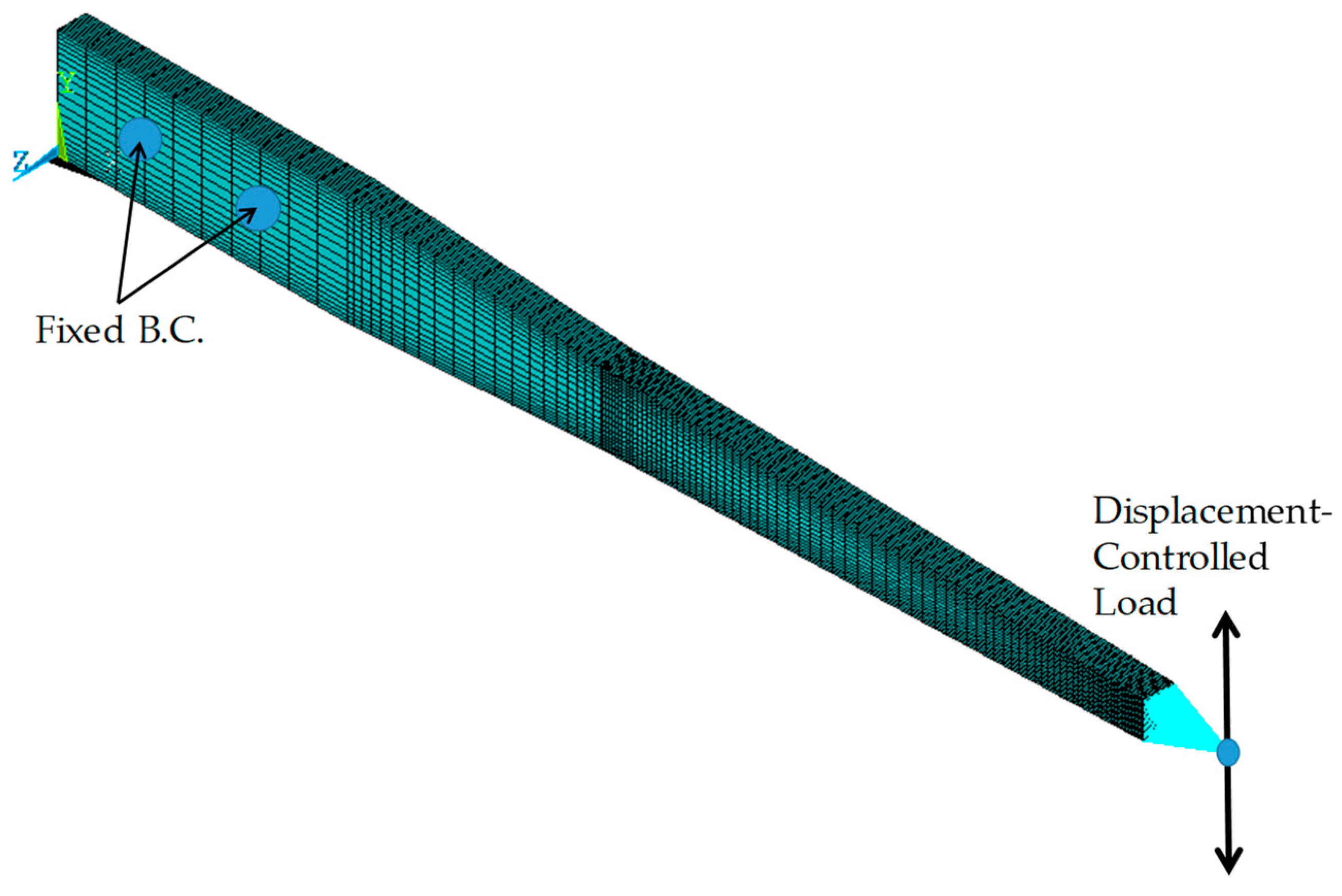
5. Design and Verification of Vertical Steel Damper

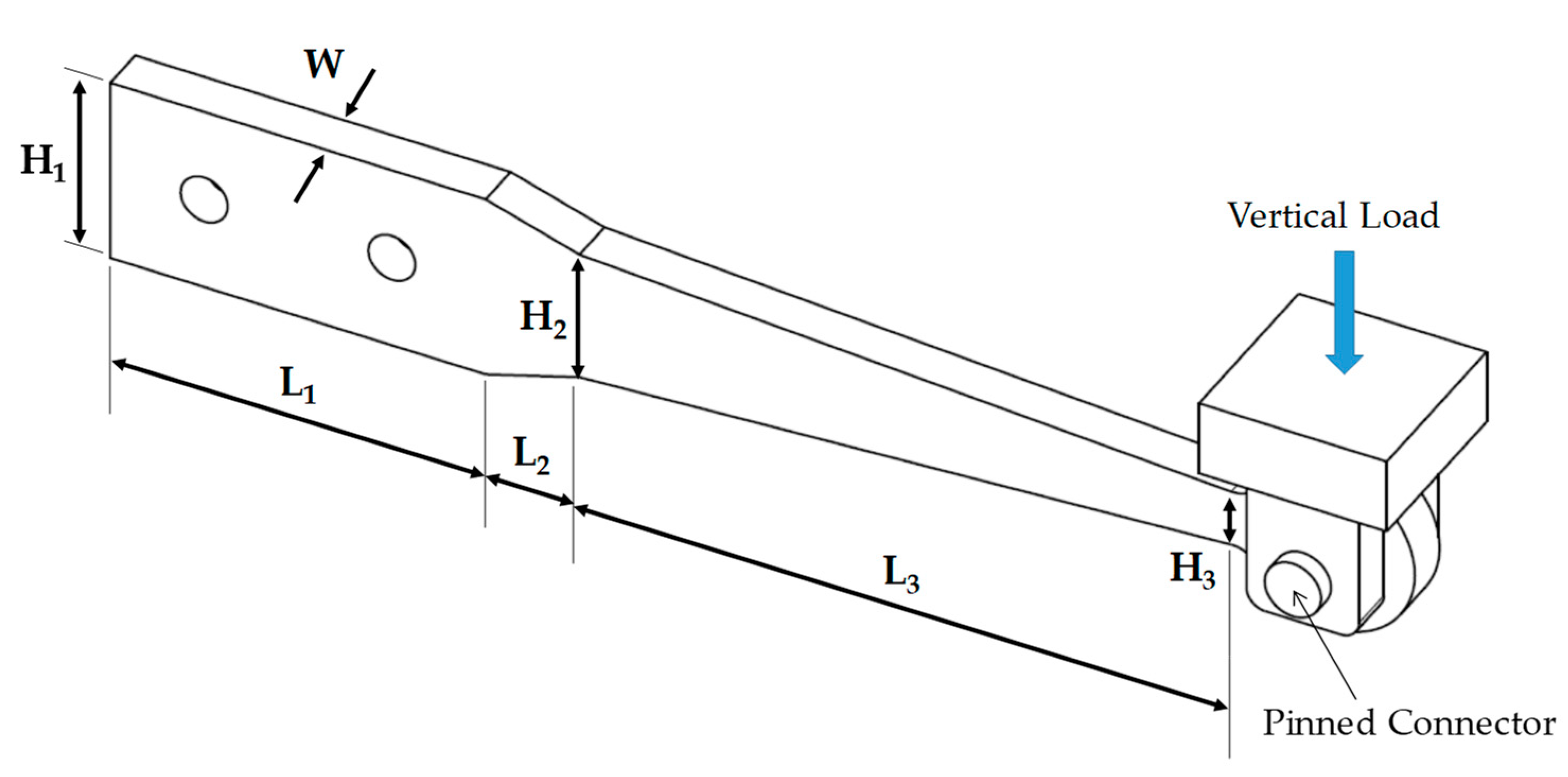
5.1. Design Configurations and Dimensions

The seismic energy dissipation performance of the steel damper reduces the vertical seismic displacement response of the spring with an appropriate size and configuration. As shown in the results of vertical seismic isolation performance in Table 4, the vertical damper should be designed enough to control the seismic displacement of the spring to avoid the interference with the LRB.
Figure 11 shows the configuration and dimensional parameters of the steel damper designed in this study. As shown in the figure, the steel damper is a thin beam plate having a tapered length. The steel damper is fixed by a specific jig mounted on the LRB upper flange, and its end is connected to the superstructure with pin joint.
In this study, the dimensions of three shapes were considered to investigate the hysteretic damping characteristics. Table 9 presents the design dimensions considered in this study.

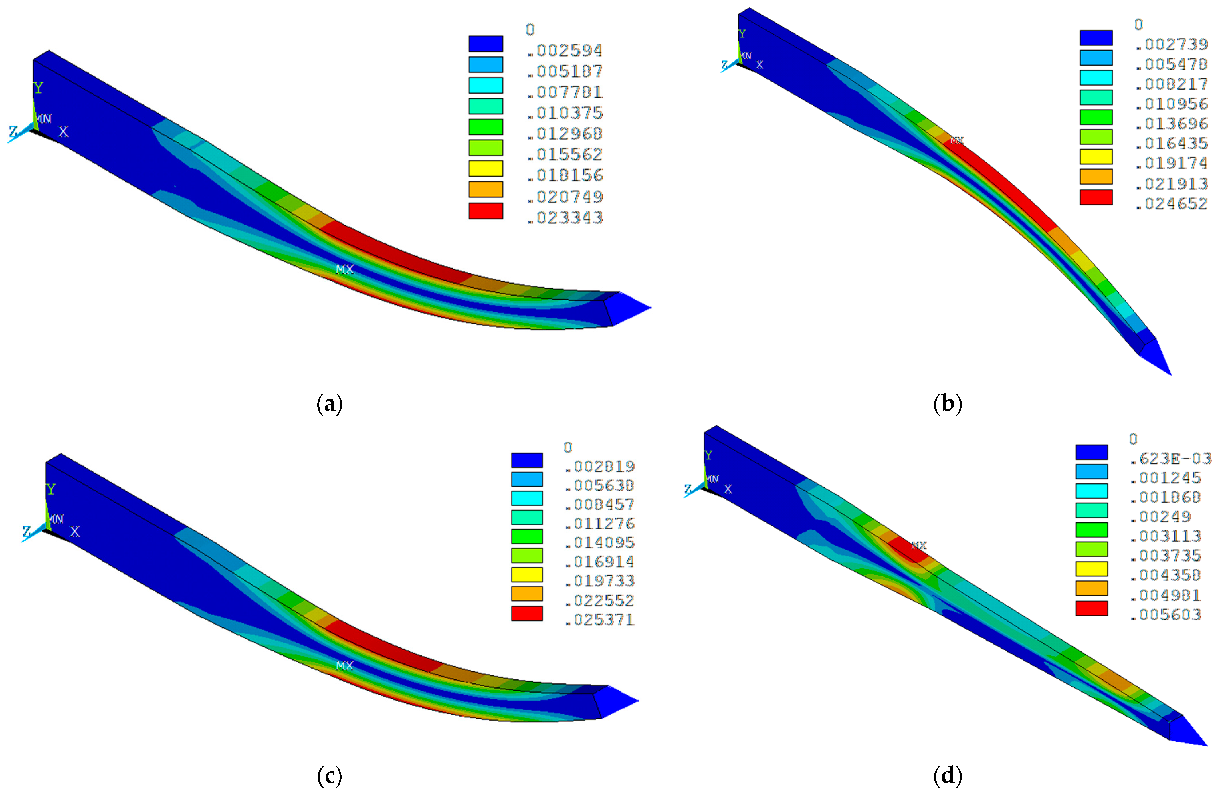
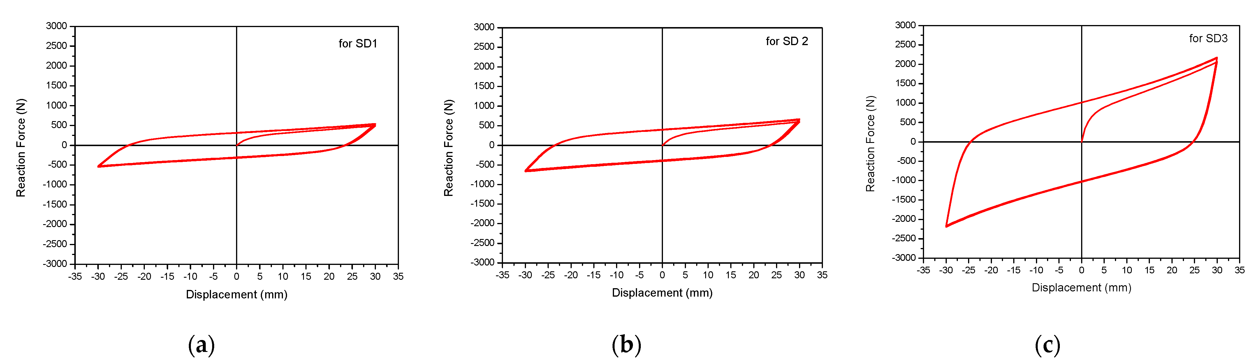
5.2. Evaluations of Energy Dissipation Performance

To evaluate the damping performance of the considered steel dampers in Table 9, force–displacement analysis was performed for the cyclic displacement load. Figure 12 shows the detailed finite element analysis model for the steel damper. As shown in the figure, a three-dimensional solid element (SOLID181) was used for the steel damper model, and it was modeled to have a sufficient number of elements and aspect ratio to enable more accurate plastic deformation analysis. As a boundary condition, a virtual node that can transmit the load from the superstructure was set and modeled so that a cyclic displacement load could be applied to the end of the steel damper using the connecting element (MPC184). As shown in Figure 12, all displacements at two pin holes are assumed to be constrained as fixed conditions, and the displacement-controlled cyclic load is applied at the end of the pinned joint.
In order to accurately describe the plastic behavior of Type 316SS, the material of the steel damper used in this study, for the finite element analysis, the following Chaboche’s inelastic constitutive equations [25,26] were used for the kinematic hardening model:
α ˙ i j = k = 1 3 [ 2 3 C k ε ˙ i j p γ k ( α i j ) k p ˙ ]
where α ˙ i j and p ˙ indicate the revolution of back stress and an accumulated plastic strain, respectively, and Ck and γk (k = 1~3) are material constants to be used in the ANSYS program.
For the isotropic hardening model, the inelastic Voce model [27] is used as follows:
R ˙ = b [ Q R ] p ˙
where R ˙ indicates the revolution of drag stress, and b and Q are material constants.
Table 10 is the material constants for Type 316 stainless steel used in the above inelastic material constitutive equations [28].
To evaluate the hysteretic damping performance of the steel damper, the vertical cyclic displacement range was set to ±30 mm and inelastic finite element analysis was performed on the triangular waveform input.
Figure 13 shows the distribution of an equivalent plastic deformation for the steel damper of SD2 during five cycles. As shown in the figure, the maximum equivalent plastic strain occurs at the upper and lower surfaces of the middle part of the steel damper by about 2.5%, and after the final fifth cyclic load, the maximum residual plastic strain remains about 0.56% at the transition region.
Figure 14 presents the analysis results of an equivalent plastic strain time history at the node where the maximum plastic strain occurs for SD2. As shown in the figure, the maximum equivalent plastic strain in the middle of the steel damper is about 2.6% at the time of the maximum and minimum cyclic displacement loads. Considering that Type 316 SS material used in this study has a total elongation of 40% or more, it is expected that sufficient plastic strain margin can secure the structural integrity of the steel damper without fracture during the strong vertical earthquakes.
Figure 15 presents the analysis results of hysteretic behavior for five cycles, which is the vertical displacement–reaction force relationship of the steel damper. As shown in the figure, the effective stiffness increases in order of SD1, SD2, and SD3, and energy dissipation area increases inversely, and it can be seen that all shapes of steel dampers exhibit hysteretic behavior in which all isotropic hardening properties are quickly stabilized after about three cycles.
Table 11 presents the results of calculating the energy dissipation performance of the steel dampers from the following relational expression [16], assuming idealized bilinear hysteretic behavior extracted from the third cycle.
ζ d = W / ( 2 π K e f f D 2 )
In the above equation, W, Keff, and D represent the energy dissipation area per cyclic load, the effective stiffness, and the maximum displacement of the hysteresis curve, respectively. As shown in the table, all steel dampers designed in this study were evaluated to have damping performance with a critical damping ratio of 30% or more.

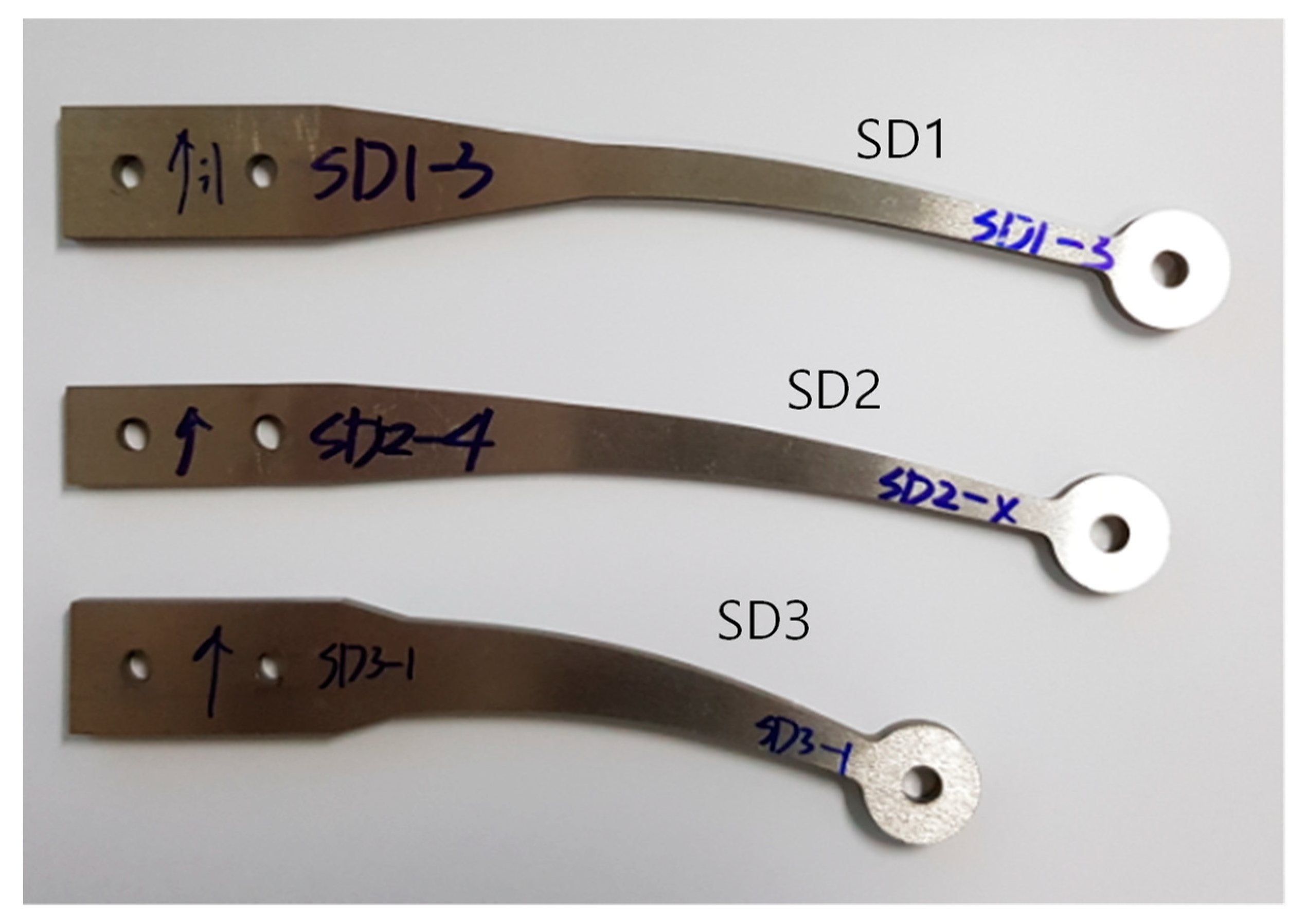
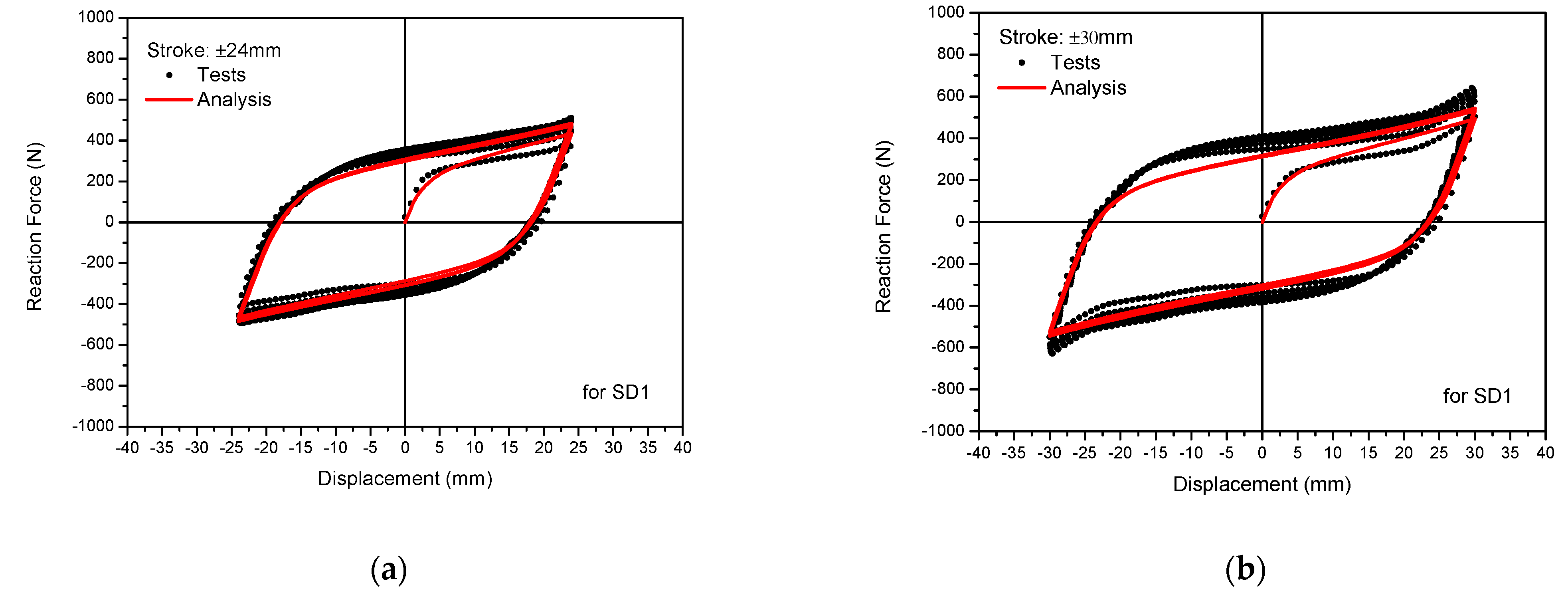
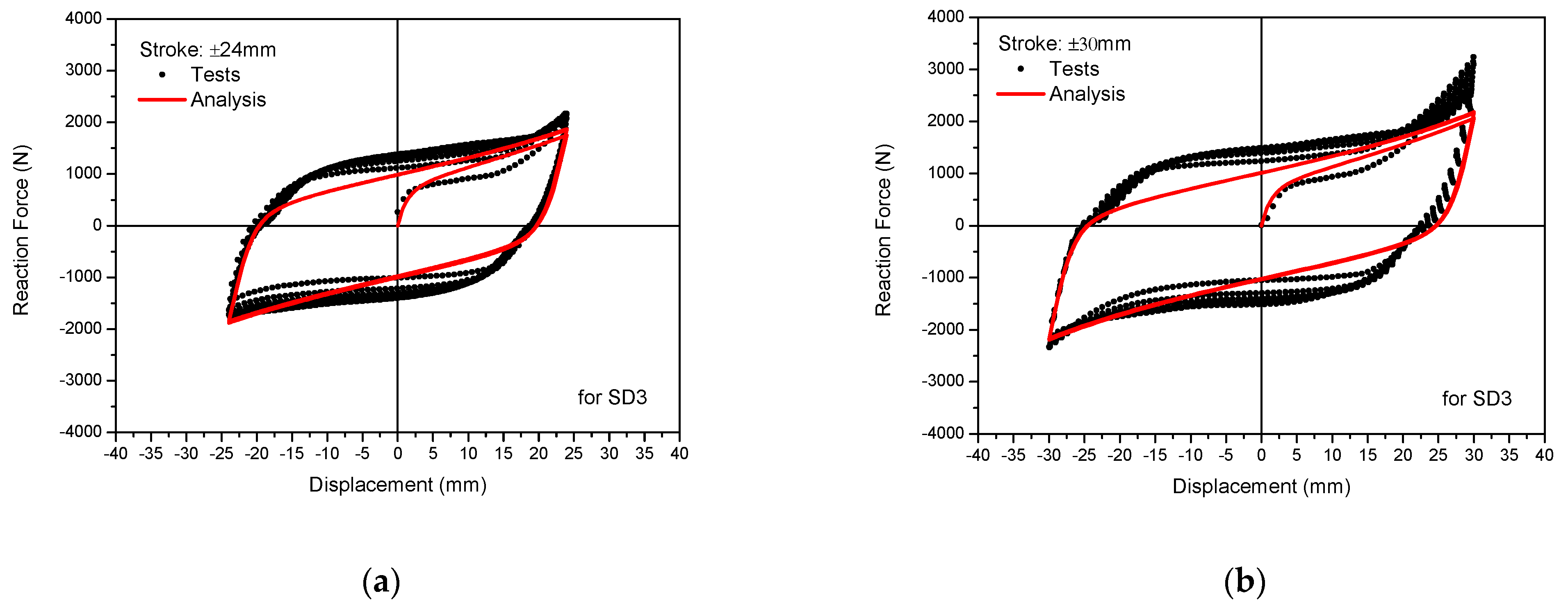
5.3. Verification Tests of Steel Damper Performance

The quasistatic test was performed to verify the hysteretic damping performance of the steel dampers in Table 11. In the verification test, three specimens were used for each steel damper ID. Figure 16 is a photograph of the steel damper specimen shapes and test facility with installation of the steel damper specimen. Table 12 shows the specifications of the DC motor-driven testing machine used in this test.
In order to verify the hysteretic energy dissipation performance, the test was carried out in five cycles for two ranges of maximum ±24 mm and ±30 mm, considering the target design displacement limit with quasistatic displacement control. The test speed applied to the quasistatic displacement control test is 5 mm/min. Figure 17 shows a photograph of the deformed shape under the maximum displacement load during the cyclic tests on the steel damper. Through visual inspection after the test, it was confirmed that there were no surface cracks on all steel damper specimens.
Figure 18, Figure 19 and Figure 20 present a comparison of the results of the hysteretic behavior of the steel dampers between the tests and inelastic analyses.
As shown in the figures above, we can see that the hysteretic behavior of the steel dampers by tests are in good agreement with the analysis results. In addition, the initial yield behavior and cyclic hardening characteristics are well matched, and all steel dampers are rapidly stabilized after three cycles. Therefore, it is expected that there is no significant change in the energy dissipation performance due to the increase in the yield strength according to the cyclic load. From the comparison results of these tests and analysis results, it is confirmed that the design of the steel damper presented in this study for application to the vertical seismic isolation device of the 3D seismic isolator can ensure the damping performance of 30% or more, which is the design target in terms of energy dissipation performance.

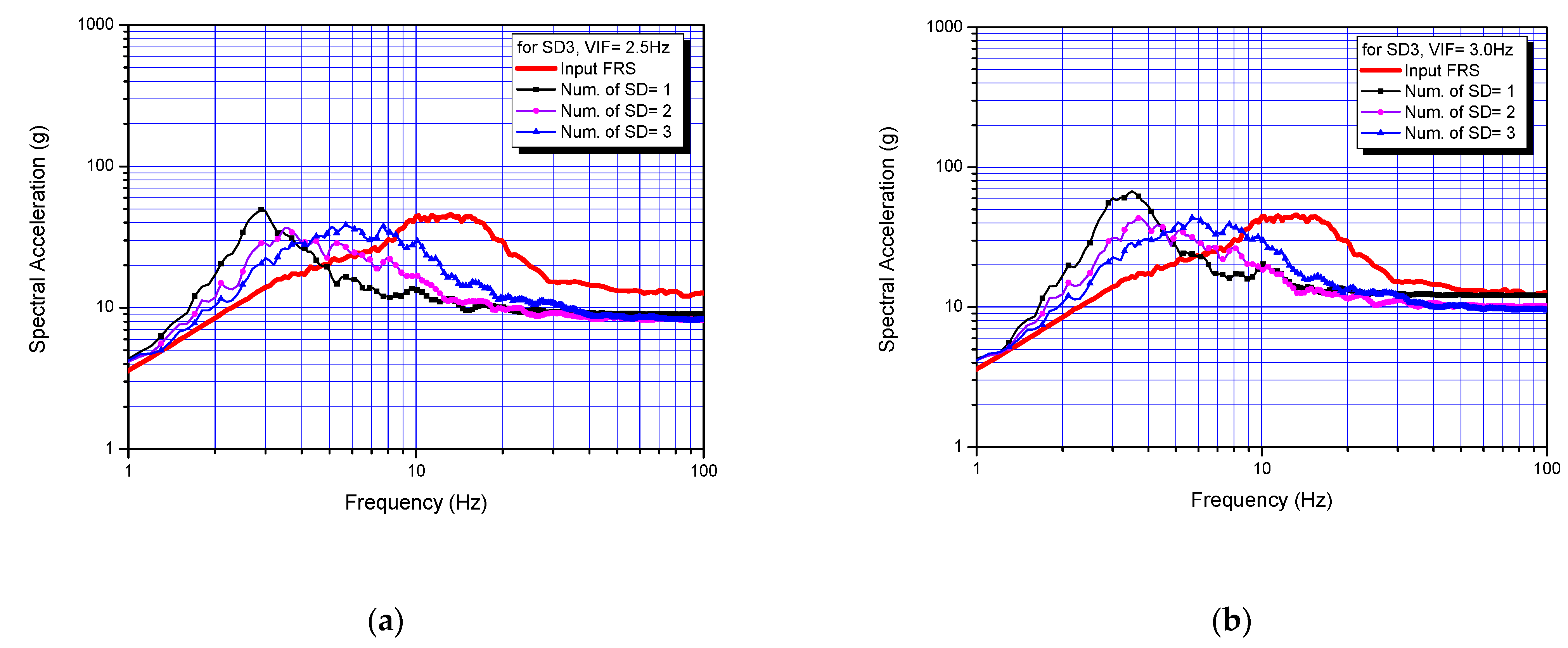
6. Evaluations of Vertical Seismic Isolation Performance

To investigate the seismic energy dissipation performance and find the adequate number of steel dampers required for the vertical displacement limits, the vertical seismic isolation performance evaluations are carried out for the chosen design VIF of 2.5 Hz and 3.0 Hz with three designed steel dampers of SD1, SD2, and SD3. The used finite element seismic analysis model is shown in Figure 4, and the steel damper is modeled by the bilinear stiffness, as identified in Table 11.
Figure 21, Figure 22 and Figure 23 present the calculation results of the floor response spectrum according to the used number of steel dampers. As shown in Figure 21, in the case of the relatively flexible steel damper SD1, the variation of the actual VIF is not sensitive to the used number of steel dampers. However, in order to obtain effective vertical seismic isolation performance, it was found that two or more SD1 dampers should be used when VIF is 2.5 Hz, and three or more when design VIF is 3.0 Hz. From the results of Figure 22, it can be seen that the steel damper SD2 shows almost similar vertical seismic isolation performance characteristics to that of the steel damper SD1.
In the case of the SD3 steel damper, which has relatively strong rigidity, as the used number of steel dampers increases, the actual VIF significantly increases, and the effective frequency range in which the seismic isolation effects can be obtained is greatly reduced, especially at lower frequency less than 10 Hz as shown in Figure 23. However, in case of vertical seismic isolation design for nuclear power plant equipment designed with a vertical natural frequency of 10 Hz or higher, it can be seen that an effective vertical seismic isolating effect can be obtained even if three steel dampers are used.
To check the vertical displacement limits, as discussed in Section 2.2 above, the seismic displacement responses were investigated for each case of the disc spring and helical coil spring. Table 13 presents the summary analysis results of the maximum vertical seismic displacement response of the vertical seismic isolation device according to the used number of steel dampers. In the table, the values of column 4 and column 5 represent the accommodatable vertical seismic displacement by extracting the static displacement from the shut displacement. As shown in the table, when the steel damper SD1 is used, five or more steel dampers must be used to satisfy the vertical displacement limits, and four or more steel dampers are required for SD2 and one or more steel dampers for SD3.

7. Conclusions

In this study, the design of a vertical seismic isolation device that can be integrally used combined with a lead-inserted small-sized laminated rubber bearing (LRB) was studied for three-dimensional seismic isolation of the nuclear power plant equipment. The overall study was based on the target equipment installed at 136 ft elevation of the typical nuclear power plant building, the input vertical seismic motions of Figure 3, and the rigid superstructure.
From the results of this study, some valuable conclusions are obtained, as follows:
  • The design VIF required for the design of the vertical seismic isolation device should be determined considering both seismic isolation performance and limitation of the vertical displacement of spring. In this study, the design VIF is recommended to be in the range of 2.5 Hz~3.0 Hz.
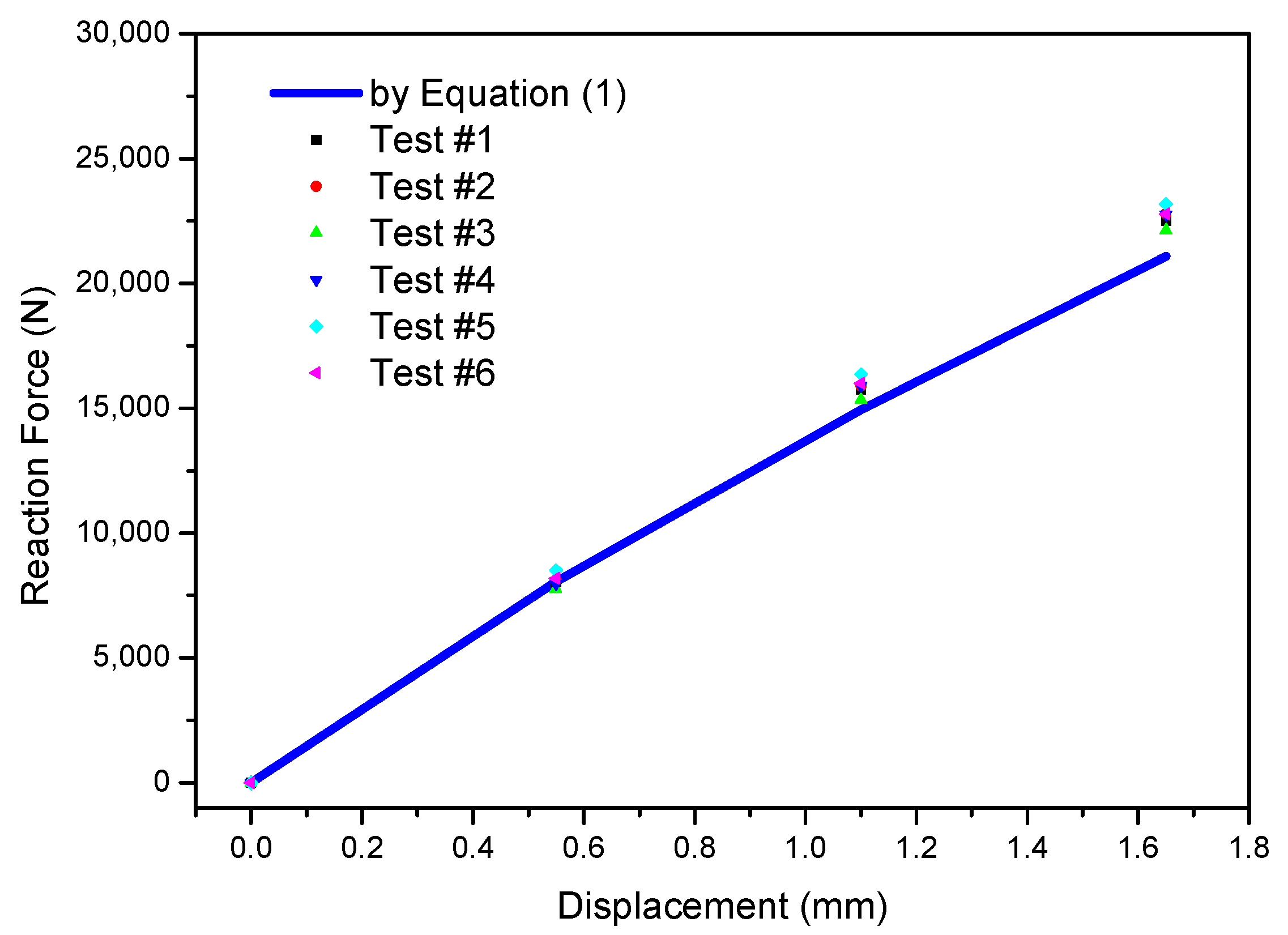
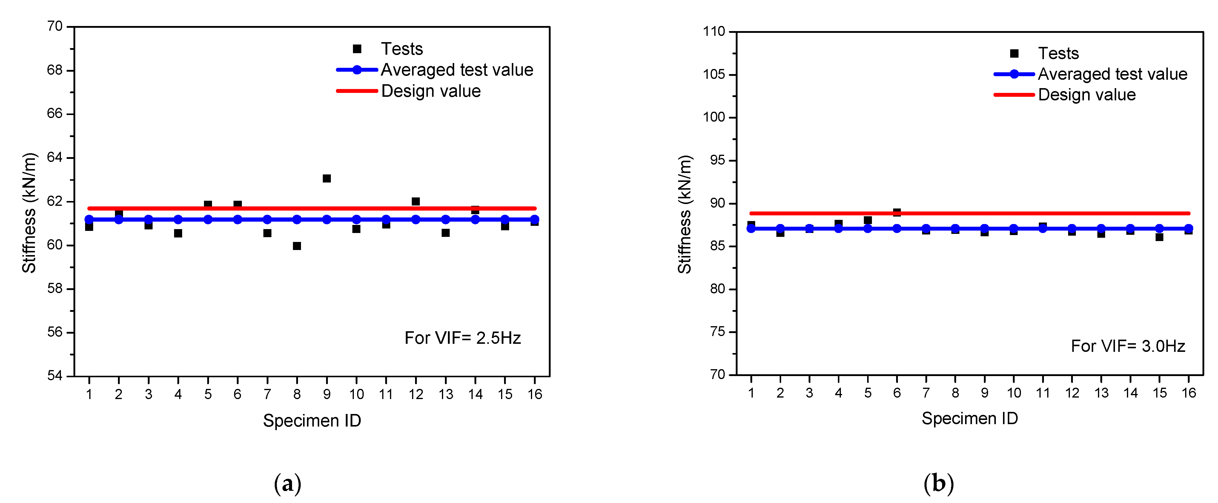
  • It is confirmed that the disc spring and the helical coil spring are useful for a stiffness design of the vertical seismic isolation device for equipment. The validation of the design values obtained from the equation of a force and displacement relationship are verified by tests.
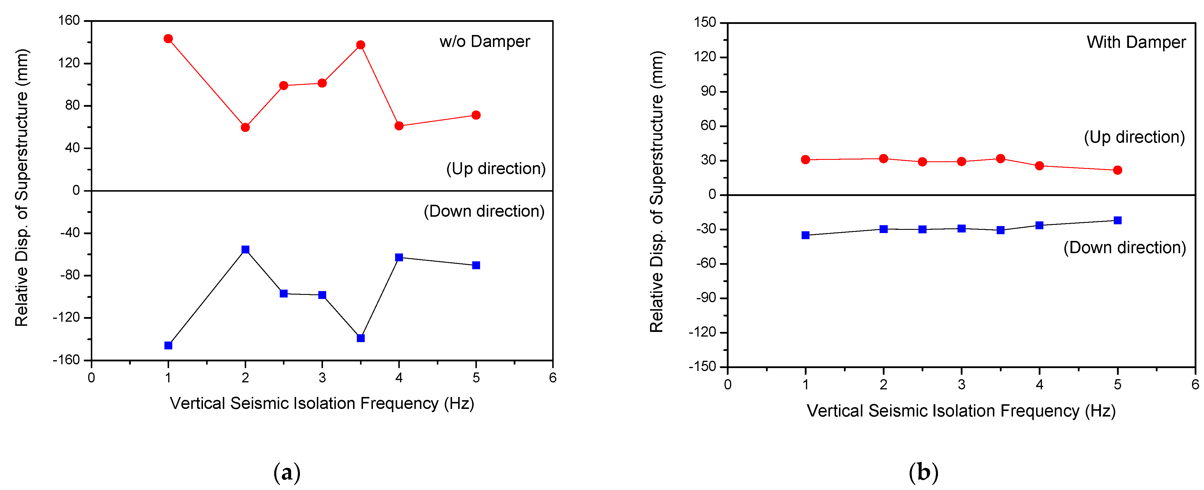
  • With an appropriate steel damper design, the vertical displacement response can be limited to the design value. In this study, the vertical displacement response is limited to 40.5 mm (disc spring) and 37.5 mm (helical coil spring) for the design VIF = 2.5 Hz and 28.1 mm for the design VIF = 3.0 Hz, which are based on the static displacement by the design vertical load of 10 kN.
  • It is verified that the designed three shapes of the steel dampers, SD1, SD2, and SD3 reveal the seismic energy dissipation performance over 30% critical damping ratio by tests and analyses.
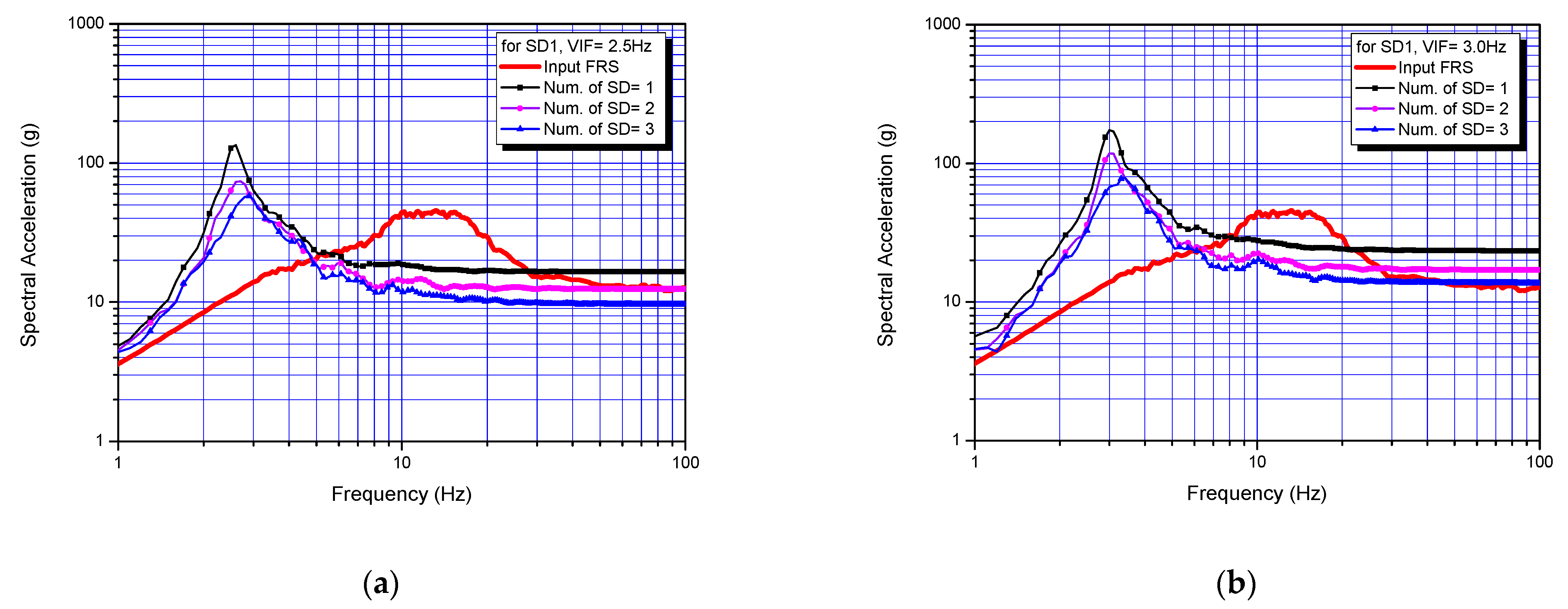
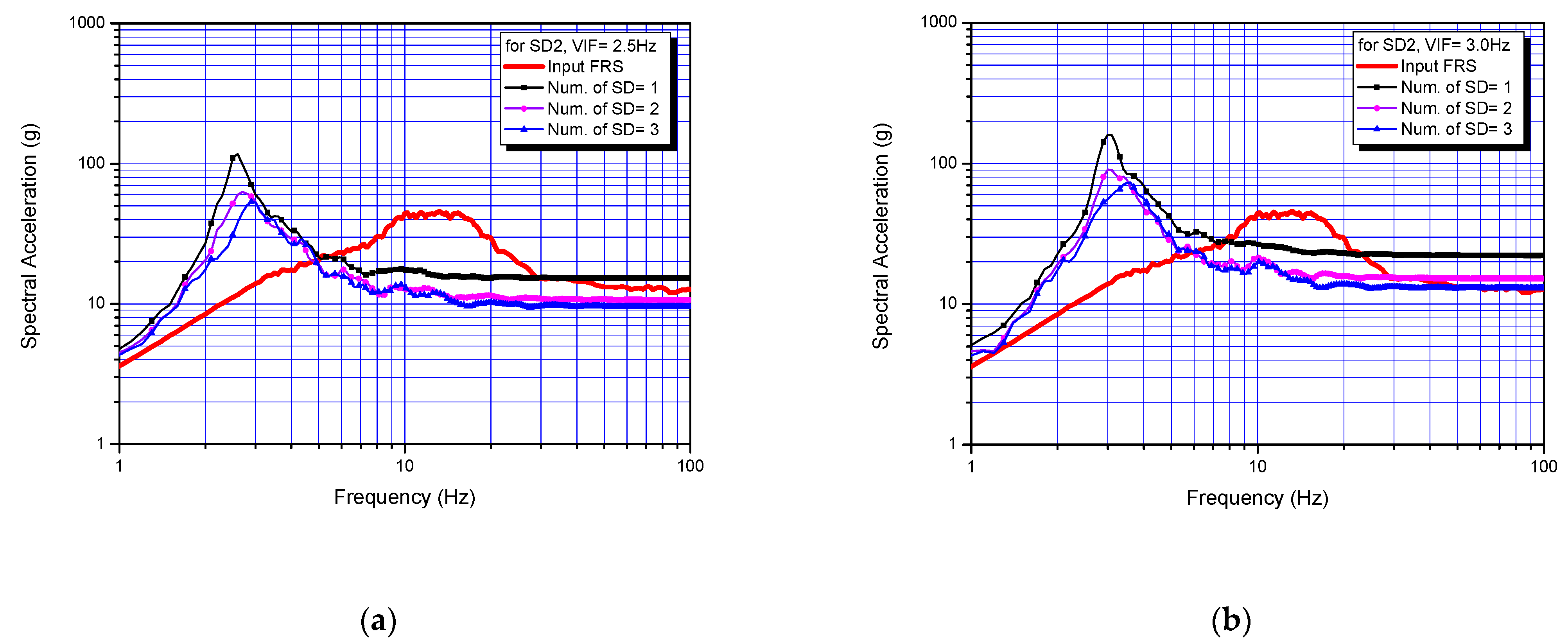
  • From the vertical seismic isolation performance analyses to find an adequate number of steel dampers satisfying the vertical displacement limits, it is found that the required number of steel dampers are at least five for SD1, four for SD2, and one for SD3.
  • The optimal VIF should be determined with consideration of the frequency characteristics of the input design response spectrum at a specific floor where the equipment is seismically isolated and the vertical natural frequency characteristics of the superstructure.

Author Contributions

Conceptualization, G.-H.K. and J.-Y.J.; methodology, G.-H.K., J.-Y.J. and J.-K.H.; validation, G.-H.K. and J.-Y.J.; formal analysis, G.-H.K.; investigation, T.-M.S. and M.-S.L.; writing—original draft preparation, G.-H.K.; writing—review and editing, J.-Y.J., J.-K.H., T.-M.S. and M.-S.L.; funding acquisition, G.-H.K. All authors have read and agreed to the published version of the manuscript.

Funding

This study was funded by the Ministry of Trade, Industry and Energy through KETEP (Korea Institute of Energy Technology Evaluation Planning). (No. 20181510102380).

Institutional Review Board Statement

Not Applicable.

Informed Consent Statement

Not Applicable.

Data Availability Statement

Not Applicable.

Acknowledgments

This study was funded by the Ministry of Trade, Industry and Energy through KETEP (Korea Institute of Energy Technology Evaluation Planning). (No. 20181510102380).

Conflicts of Interest

The authors declare no conflict of interest.

References

  1. Pierre, L. Pioneering actual use of seismic isolation for nuclear facilities. In Proceedings of the 1st Kashiwasaki International Symposium on Seismic Safety of Nuclear Installation, Kashiwasaki, Japan, 26 November 2010. [Google Scholar]
  2. Kwag, S.Y.; Kwag, J.S.; Lee, H.H.; Oh, J.H.; Koo, G.H. Enhancement in the Seismic Performance of a Nuclear Piping System using Multiple Tuned Mass Dampers. Energies 2019, 12, 2077. [Google Scholar] [CrossRef] [Green Version]
  3. Kostarev, V.; Petrenko, A.; Vasilev, P. A New Method for Essential Reduction of Seismic and External Loads on NPP’s Structures, Systems and Components. In Proceedings of the 17th International Conference on SMiRT, Prague, Czech Republic, 17–22 August 2003. [Google Scholar]
  4. Germane, L. Seismic Isolation of the Jules Horowitz Reactor. In Proceedings of the 1st Kashiwasaki International Symposium on Seismic Safety of Nuclear Installation, Kashiwasaki, Niigata, Japan, 26 November 2010. [Google Scholar]
  5. Tajirian, F.F.; Schrag, M.R. Conceptual design of seismic isolation for the PRISM liquid metal reactor. In Proceedings of the Transactions of the 9th International Conference on Structural Mechanics in Reactor Technology, Switzerland, Lausanne, 17–21 August 1987; Volume K2, pp. 705–710. [Google Scholar]
  6. Okamura, S.; Kamishima, Y.; Negishi, K.; Sakamoto, Y.; Kitamura, S.; Kotake, S. Seismic isolation design for JSFR. J. Nucl. Sci. Technol. 2011, 48, 688–692. [Google Scholar] [CrossRef]
  7. Koo, G.H.; Kim, S.H.; Kim, J.B. Seismic Modeling and Analysis for Sodium-cooled Fast Reactor. Struct. Eng. Mech. 2012, 43, 475–502. [Google Scholar] [CrossRef]
  8. Morishita, M.; Kitamura, S.; Moro, S.; Kamishima, Y.; Takahiro, S. Study on 3-dimensional seismic isolation system for next generation nuclear power plant-vertical component isolation system with coned disk spring, Technical Report No. 620. In Proceedings of the 13th World Conference on Earthquake Engineering, Vancouver, BC, Canada, 1–6 August 2004. [Google Scholar]
  9. Zhou, Z.; Wong, J.; Mahin, S. Potentiality of Using Vertical and Three-Dimensional Isolation Systems in Nuclear Structures. Nucl. Eng. Technol. 2016, 48, 1237–1251. [Google Scholar] [CrossRef] [Green Version]
  10. Tajirian, F.F.; Kelly, J.M.; Aiken, I.D.; Veljovich, W. Elastomeric bearings for three-dimensional seismic isolation. In Proceedings of the 1990 ASME PVP Conference, Nashville, TN, USA, 17–21 June 1990. [Google Scholar]
  11. Suhara, J. Research on 3D base isolation system applied to new power reactor 3D seismic isolation device with rolling seal type air spring: Part 1. In Proceedings of the SMiRT 17, Paper #K09e4, Prague, Czech Republic, 17–22 August 2003. [Google Scholar]
  12. Takahashi, O.; Aida, H.; Suhara, J.; Matsumoto, R.; Tsuyuki, Y.; Fujita, T. Construction of civil building using three dimensional seismic isolation system: Part 1, design of building using three dimensional seismic isolation system. In Proceedings of the 14th World Conference on Earthquake Engineering, Beijing, China, 12–17 October 2008. [Google Scholar]
  13. Ogiso, S.; Nakamura, K.; Suzuki, M.; Moro, S. Development of 3D seismic isolator using metallic bellows. In Proceedings of the 17th International Conference on Structural Mechanics in Reactor Technology (SMiRT 17), Prague, Czech Republic, 17–22 August 2003. [Google Scholar]
  14. Wong, J.; Lakshmipath, L.; Armas, P.J.; Paredes, A.E.; Park, C.; Campos, J.A. Design and Small-Scale Testing of 3D Printed Seismic Isolators. In Proceedings of the 2019 American Society for Engineering Education 126th Annual Conference & Exposition, Tampa, FL, USA, 15 June 2019. [Google Scholar]
  15. Okada, Y.; Suhara, J.; Tamura, T.; Ohta, K.; Moro, S. Development of Three Dimensional Seismic Isolation Device with Laminated Rubber Bearing and Rolling Seal Type Air Spring. In Proceedings of the GENES4/ANP2003, Kyoto, Japan, 15–19 September 2003. [Google Scholar]
  16. Koo, G.H.; Jung, J.Y.; Lee, J.H.; Shin, T.M. Development of Small-Sized Lead Inserted Laminated Rubber Bearing for Nuclear Component Seismic Isolation. Energies 2020, 13, 3193. [Google Scholar] [CrossRef]
  17. Koo, G.H.; Shin, T.M.; Ma, S.J. Shaking Table Tests of Lead Inserted Small-Sized Laminated Rubber Bearing for Nuclear Component Seismic Isolation. Appl. Sci. 2021, 11, 4431. [Google Scholar] [CrossRef]
  18. Sheikhi, J.; Fathi, M. Natural Rubber Bearing Incorporated with Steel Ring Damper (NRB-SRD). Int. J. Steel Struct. 2020, 20, 23–34. [Google Scholar] [CrossRef]
  19. Asgari, A.; Osma, S.A.; Azlan, A. Application of HDR Dampers in Seismic Protection of LRB-Controlled Cable-Stayed Bridges. In Proceedings of the Istanbul Bridge Conference, Istanbul, Turkey, 11–13 August 2014. [Google Scholar]
  20. Roh, J.E.; Hur, M.W.; Choi, H.H.; Lee, S.H. Development of a Multiaction Hybrid Damper for Passive Energy Dissipation. Shock. Vib. 2018, 2018. [Google Scholar] [CrossRef] [Green Version]
  21. Dolati, S.S.K.; Mehrabi, A.; Dolati, S.S.K. Application of Viscous Damper and Laminated Rubber Bearing Pads for Bridges in Seismic Regions. Metals 2021, 11, 1666. [Google Scholar] [CrossRef]
  22. Nuclear Regulatory Commission. Design Response Spectra for Seismic Design of Nuclear Power Plants; Regulatory Guide 1.60; Nuclear Regulatory Commission: Rockville, MD, USA, 1973. [Google Scholar]
  23. ANSYS Mechanical APDL Release 15.0; ANSYS, Inc.: Canonsburg, PA, USA, 2013.
  24. Norton, R.L. Machine Design, An Integrated Approach; Prentice Hall: Upper Saddle River, NJ, USA, 1996. [Google Scholar]
  25. Chaboche, J.L.; Rousselier, G. On the plastic and viscoplastic constitutive equations—Part II: Application of internal variable concepts to the 316 stainless steel. J. Press. Vessel. Technol. 1983, 105, 159–164. [Google Scholar] [CrossRef]
  26. Chaboche, J.L. Constitutive equations for cyclic plasticity and cyclic viscoplasticity. Int. J. Plast. 1989, 5, 247–302. [Google Scholar] [CrossRef]
  27. Voce, E. A Practical Strain hardening Function. Metallurgia 1955, 51, 219–226. [Google Scholar]
  28. Koo, G.H.; Yoon, J.H. Inelastic Material Models of Type 316H for Elevated Temperature Design of Advanced High Temperature Reactors. Energies 2020, 13, 4548. [Google Scholar] [CrossRef]
Figure 1. Overall design concept of integrated 3-dimensional seismic isolator (half-symmetric view).
Applsci 12 00320 g001
Figure 2. Schematics of 3D seismic isolator’s motions: (a) Without loads; (b) with vertical static load; (c) with horizontal and vertical seismic loads.
Applsci 12 00320 g002
Figure 3. Used vertical seismic input motion (PGA = 0.5 g): (a) Floor response spectrum; (b) acceleration time history; (c) displacement time history.
Applsci 12 00320 g003
Figure 4. Schematics of simple seismic analysis model used for sensitivity analysis: (a) Finite element model of vertical seismic isolation device; (b) bilinear model of steel damper.
Applsci 12 00320 g004
Figure 5. Spectral acceleration response of superstructure for various design VIF.
Applsci 12 00320 g005
Figure 6. Maximum spring displacement response for various design VIF: (a) Without steel damper; (b) with steel damper.
Applsci 12 00320 g006
Figure 7. Schematics of the disc spring configurations and dimensional design parameters.
Applsci 12 00320 g007
Figure 8. Comparison of the linearity characteristics between tests and calculation values by formula for a single disc spring.
Applsci 12 00320 g008
Figure 9. Configuration and dimensional parameters for helical coil spring.
Applsci 12 00320 g009
Figure 10. Comparison of stiffness between tests and design values of helical coil springs: (a) For VIF = 2.5 Hz; (b) for VIF = 3.0 Hz.
Applsci 12 00320 g010
Figure 11. Configurations and dimensional parameters of steel damper.
Applsci 12 00320 g011
Figure 12. Finite element model of steel damper for energy dissipation analysis.
Applsci 12 00320 g012
Figure 13. Analysis results of equivalent plastic strain distributions and deformation shapes of steel damper, SD2 during ±30 mm stroke: (a) After 1/4 cycle; (b) after 1(3/4) cycles; (c) after 3(1/4); (d) after 5 cycles.
Applsci 12 00320 g013
Figure 14. Analysis results of equivalent plastic strain time history during cyclic load for SD2.
Applsci 12 00320 g014
Figure 15. Analysis results of hysteretic response for steel dampers: (a) SD1; (b) SD2; (c) SD3.
Applsci 12 00320 g015
Figure 16. Photos of steel damper specimen and test facility: (a) Steel damper specimen; (b) test facility with specimen.
Applsci 12 00320 g016
Figure 17. Deformed shapes of steel dampers after the maximum displacement loads.
Applsci 12 00320 g017
Figure 18. Comparison results of hysteretic behavior between tests and analyses for steel damper, SD1: (a) for ±24 mm stroke; (b) for ±30 mm stroke.
Applsci 12 00320 g018
Figure 19. Comparison results of hysteretic behavior between tests and analyses for steel damper, SD2: (a) for ±24 mm stroke; (b) for ±30 mm stroke.
Applsci 12 00320 g019
Figure 20. Comparison results of hysteretic behavior between tests and analyses for steel damper, SD3: (a) for ±24 mm stroke; (b) for ±30 mm stroke.
Applsci 12 00320 g020
Figure 21. Results of vertical response spectrum for steel damper, SD1: (a) Design VIF = 2.5 Hz; (b) design VIF = 3.0 Hz.
Applsci 12 00320 g021
Figure 22. Results of vertical response spectrum for steel damper, SD2: (a) Design VIF = 2.5 Hz; (b) design VIF = 3.0 Hz.
Applsci 12 00320 g022
Figure 23. Results of vertical response spectrum for steel damper, SD3: (a) Design VIF = 2.5 Hz; (b) design VIF = 3.0 Hz.
Applsci 12 00320 g023
Table 1. Summary of 3D seismic isolator design parameters [16].
Isolation Devices Design ParametersDesign Value
Horizontal
Seismic Isolation Device (LRB)
 Outer diameter (mm)100
 Lead plug diameter (mm)21.5
 Total LRB height (mm)34
 Shape factor (S1, S2)9.9, 5.0
 Design vertical load (kN)10
 Design shear disp. (mm)35 (175%)
 Beyond design shear disp. (mm)80 (400%)
Vertical
Seismic Isolation Device
 Housing diameter (mm)450
 Total height (mm)140~360
 Design vertical load (kN)10
Table 2. Parameter values for simple seismic analysis model.
Design VIF
(Hz)
Required Vertical
Stiffness
(kN/m)
Static Disp. for 10 kN
(mm)
1.039.5253.3
2.0157.963.3
2.5246.740.5
3.0355.328.1
3.5483.620.7
4.0631.715.8
5.0987.010.1
Table 3. Preliminary design parameter values for sensitivity analysis.
ParametersValues
 Superstructure mass (kg)1000
 Stiffness of vertical spring, KVS (N/m)Variable depending on VIF
 Damping of vertical spring, CVS (kg/s)62.8
 Elastic stiffness of steel damper, Ke (N/m)621,700
 Tangential stiffness of steel damper, Kt (N/m)36,460
 Characteristic strength, Fslide (N)990
 Struct. Damping of steel damper, CSD (kg/s)0
Table 4. Summary results of vertical seismic isolation performance with design VIF.
Design
VIF
(Hz)
Effective
Frequency Range (Hz)
ZPA 1
Response
(g)
Max. Displacement (mm)VIF
with Damper
(Hz)
Without DamperWith Damper
1.02.6<0.37+143.4/−146.0+30.8/−35.11.8
2.04.2<0.73+59.7/−55.3+31.7/−29.82.4
2.55.0<0.97+99.2/−97.0+28.9/−30.02.9
3.06.2~80.01.27+101.3/−98.3+29.2/−29.33.5
3.57.5~26.01.78+137.6/−139.0+31.7/−30.73.8
4.08.0~24.01.91+61.2/−62.9+25.6/−26.54.2
5.09.5~20.02.40+71.2/−70.4+21.6/−22.15.2
1 Note that ZPA of input floor response spectrum is 1.27 g.
Table 5. Design parameter values for a single disc spring.
Design Parameters of Disc SpringValues
 Outer diameter, D (mm)80
 Inner diameter, d (mm)41
 Thickness, t (mm)4
 Shut displacement, h (mm)2.2
 Height, H(=t + h) (mm)6.2
 Design vertical load, F (kN)10
 Young’s modulus, E (GPa)190
 Poisson ratio, ν0.27
Table 6. Design summary of stacked disc springs for various design VIF.
Design
VIF
(Hz)
Required
Stiffness
(kN/m)
Required
Number of
Disc Spring 1
Total Height 1
(mm)
Total Shut
Disp.
(mm)
Static Disp. for 10 kN
(mm)
1.039.535221821408253.3
2.0157.98854635263.3
2.5246.75836023240.5
3.0355.34024816028.1
3.5483.63018612020.7
4.0631.7221368815.8
5.0987.016996410.1
1 In case of a serial stack.
Table 7. Design summary of helical coil spring system with design VIF.
Design
VIF
(Hz)
Required
Stiffness
(kN/m)
Number of
Spring 1
Required
Number of
Coil Turns
Total Height
(mm)
Total Shut
Displacement
(mm)
1.039.5429880368
2.0157.947.5230110
2.5246.74516078
3.0355.343.513560
3.5483.642.510050
4.0631.741.89045
5.0987.04---
1 Parallel mounting.
Table 8. Summary results of final design parameter values for a single helical coil spring.
Design ParametersValues
VIF = 2.5 HzVIF = 3.0 Hz
 Outer diameter, Do (mm)100100
 Coil diameter, d (mm)1212
 Mean spring diameter, D = Dod (mm)8888
 Number of coil turns, Na53.5
 Pitch, p (mm)27.2031.71
 Total height, Lf (mm)160135
 Assembled height, La (mm)119.47106.86
 Minimum height, Lm, (mm)7860
 Shear modulus, G (GPa)7575
 Spring constant, K (kN/m)61.6988.83
Table 9. Dimensions for steel dampers (mm).
Steel Damper
ID
L1L2L3H1H2H3W
SD140408020855
SD2403575151054
SD3401070201465
Table 10. Material constants for inelastic material models at room temperature.
Materialσyo
(MPa)
E
(GPa)
C1
× 109
C2
× 109
C3
× 109
γ1
× 103
γ2
× 103
γ3bQ
× 106
Type 316SS13519012020.210.671.01.01.045.085
Table 11. Evaluation results of energy dissipation capacity of steel dampers.
Steel Damper
ID
Kt
(kN/m)
Ke
(kN/m)
Fslide
(N)
W1
(N·m)
Critical Damping
Ratio (%)
SD17.21100.82330.6425.4435.17
SD29.00127.21413.2431.8735.25
SD337.00695.771064.6190.6031.70
1W is the area of hysteresis curve indicating the energy dissipation per cycle (EDC).
Table 12. Performance characteristics of test facility.
ItemPerformance
Facility model nameINSTRON 5982
Max. loading (kN)100
Footprint dimensions (mm)1130 × 777
Height (mm)2273
Control axes1
Max. displacement (mm)1330
Min. speed (mm/min)0.0001
Max. speed (mm/min)1016
Excitation mechanismBrush DC Motor
Control softwareINSTRON Bluehill 3
Table 13. Results of vertical seismic displacement responses of vertical isolation device.
Steel Damper ID# of
Dampers
Peak Vertical Seismic Disp.
Response (mm)
(DsdDdw) (1)
for Disc Spring (mm)
(DsdDdw) (1)
for Helical Coil Spring (mm)
Vertical Disp.
Limits (mm)
VIF = 2.5 HzVIF = 3.0 Hz2.5 Hz3.0 Hz2.5 Hz3.0 Hz2.5 Hz3.0 Hz
SD11−63.6/+62.1−63.2/+63.786.559.937.532.040.5 (2)28.1
2−45.1/+41.8−44.3/+42.7
3−30.9/+32.1−33.5/+33.6
4−29.8/+28.2−29.0/+30.5
5−25.9/+25.7−26.1/+27.9
SD21−57.8/+55.0−59.8/+59.786.559.937.532.040.5 (2)28.1
2−37.2/+36.3−38.6/+33.6
3−30.2/+28.7−29.7/+30.6
4−25.8/+25.6−26.0/+27.8
SD31−28.0/+27.9−27.9/+28.386.559.937.532.040.5 (2)28.1
2−18.9/+17.8−16.4/+18.7
3−13.6/+9.9−13.3/+10.5
(1)Dsd: Shut displacement, Ddw: Static displacement due to design vertical load of 10 kN. (2) It will be 37.5 mm in the case of helical coil spring.
Publisher’s Note: MDPI stays neutral with regard to jurisdictional claims in published maps and institutional affiliations.

