Modeling and Validation of a Passive Truss-Link Mechanism for Deployable Structures Considering Friction Compensation with Response Surface Methods
Abstract
:1. Introduction
2. Configuration Design of Truss-Link Mechanism
2.1. Concept Design
2.2. Configuration Design
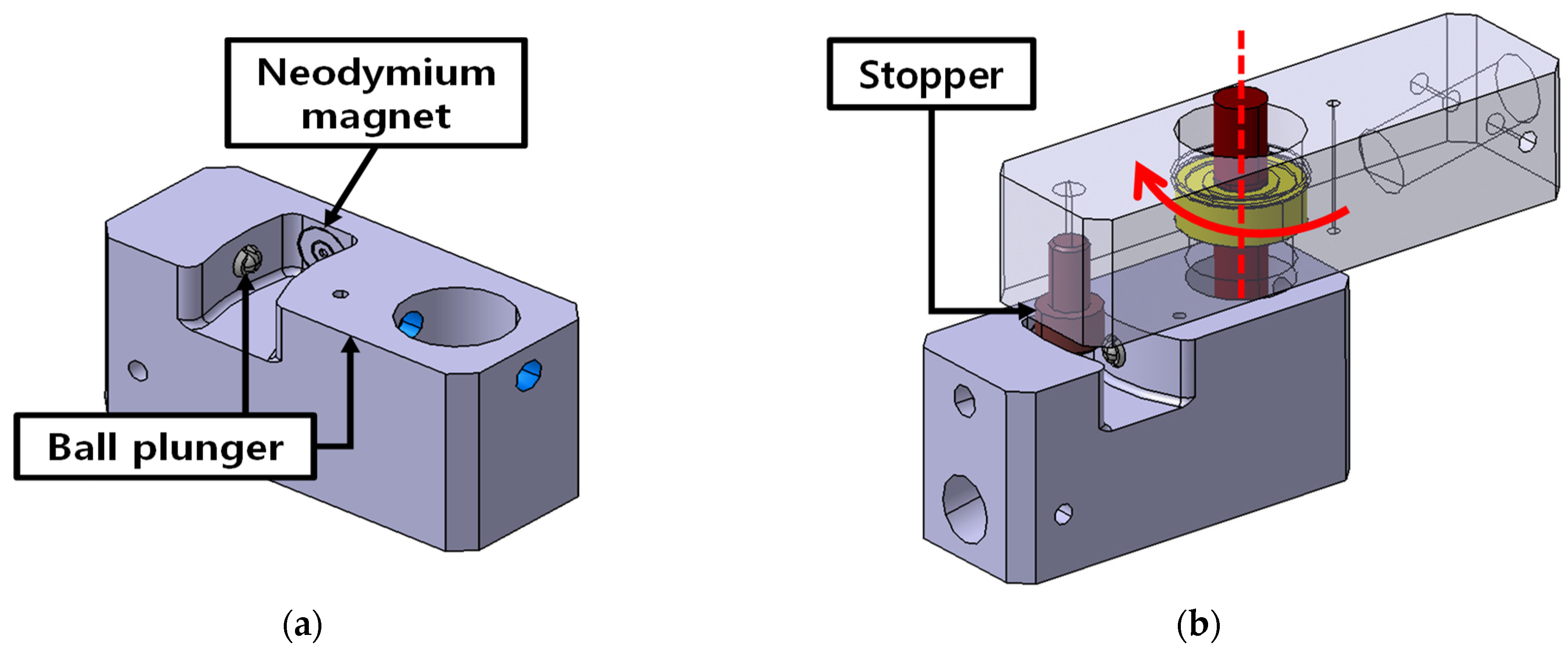
2.3. Latching Mechanism
3. Deployment Dynamics
3.1. Modeling of Kinematic Joints and Latching Mechanism
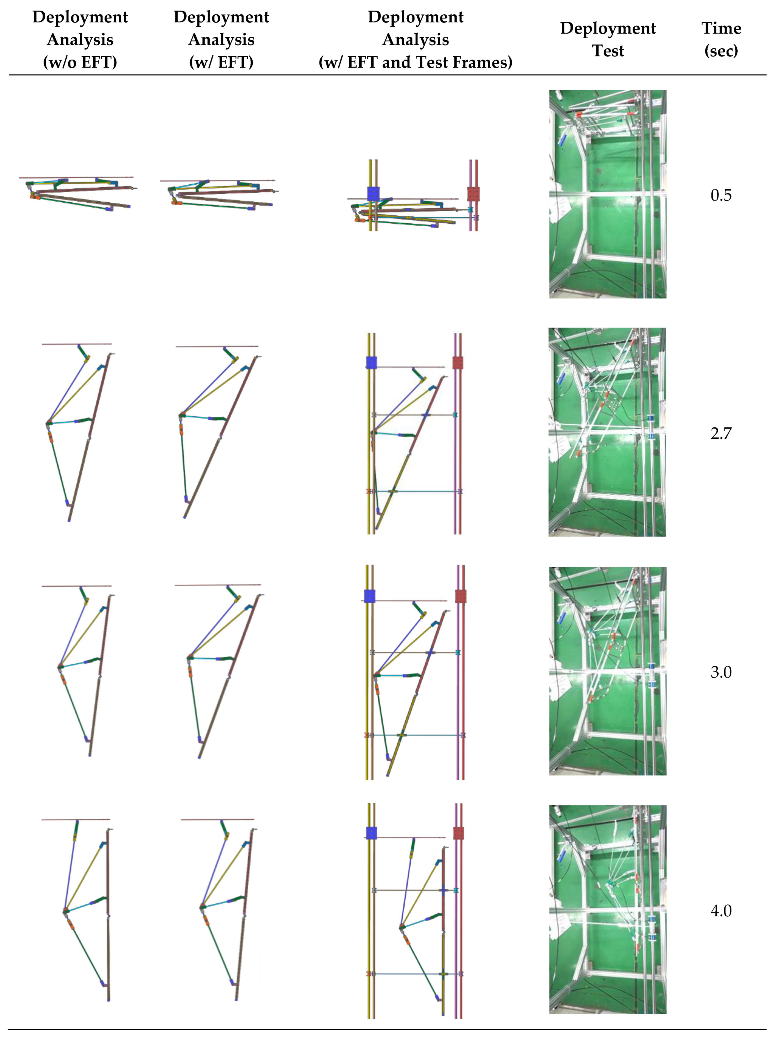
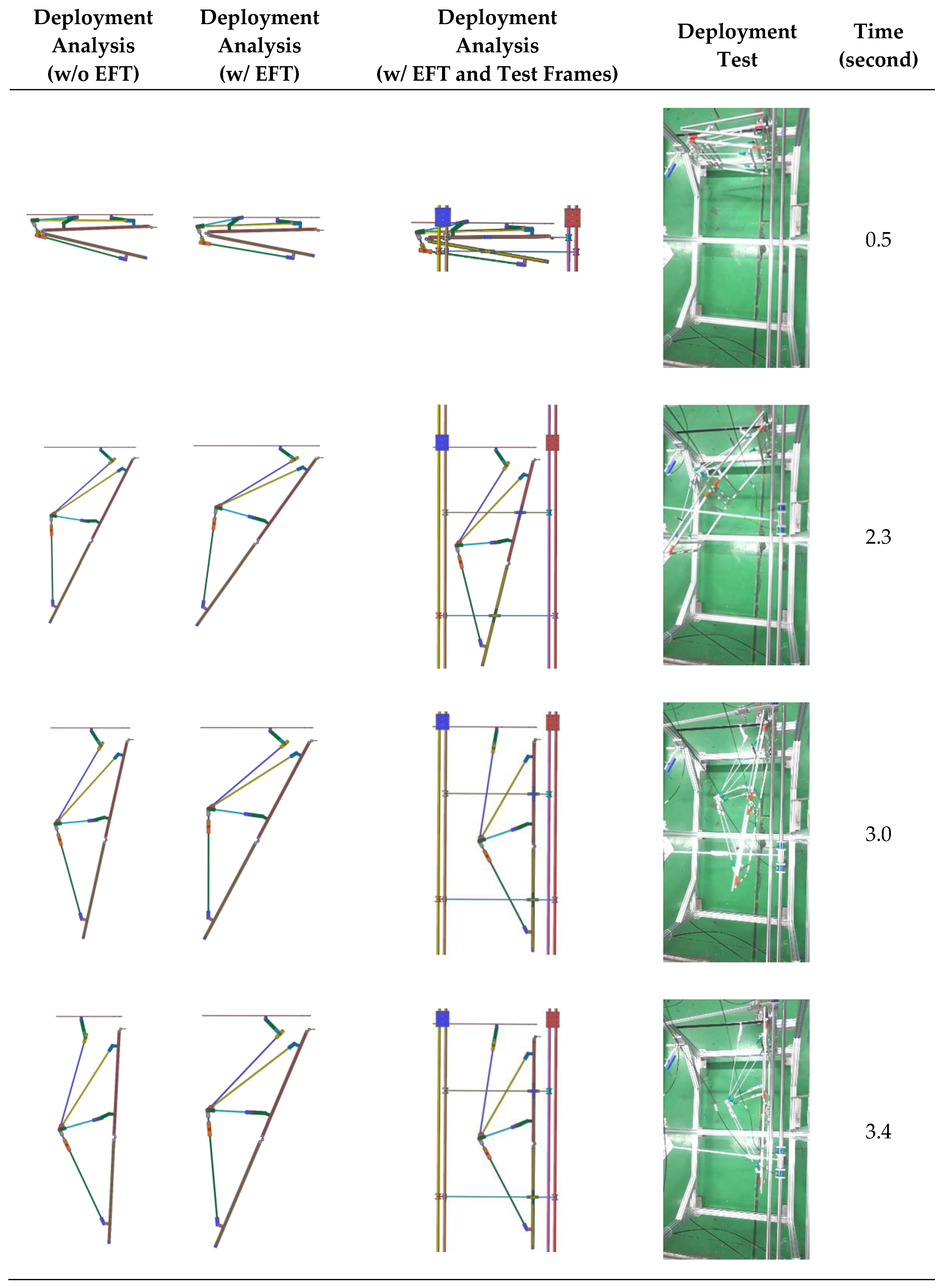
3.2. Deployment Dynamics Analysis
4. Deployment Test
4.1. Test Configuration and Test Cases
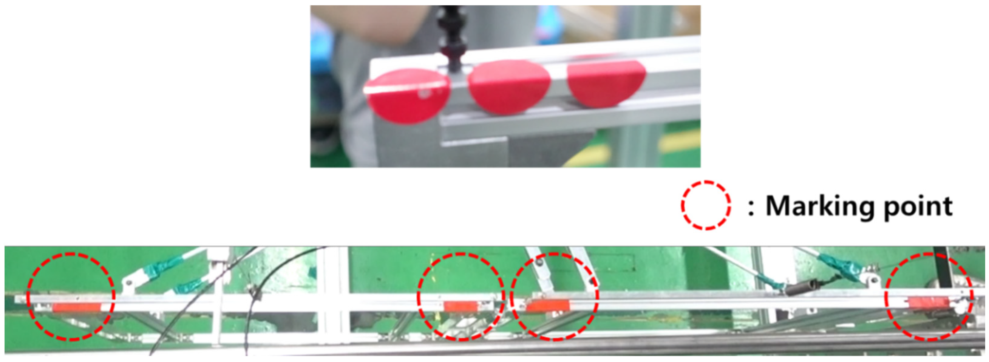
4.2. Modeling of Friction and Trajectory Error
4.3. Response Surface Methodology for Friction Identification
4.4. Torque Margin Evaluation
5. Conclusions
Author Contributions
Funding
Institutional Review Board Statement
Informed Consent Statement
Data Availability Statement
Conflicts of Interest
References
- Kim, S.-Y. SAR Antenna Technology. In Proceedings of the Korea Electromagnetic Engineering Society, Ilsan, Korea, 25 November 2011. [Google Scholar]
- Park, T.-Y.; Kim, S.-Y.; Yi, D.-W.; Jung, H.-Y.; Lee, J.-E.; Yun, J.-H.; Oh, H.-U. Thermal Design and Analysis of Unfurlable CFRP Skin-Based Parabolic Reflector for Spaceborne SAR Antenna. Int. J. Aeronaut. Space Sci. 2021, 22, 433–444. [Google Scholar] [CrossRef]
- Kim, D.-Y.; Lim, J.H.; Jang, T.-S.; Cha, W.H.; Lee, S.-J.; Oh, H.-U.; Kim, K.-W. Optimal design of stiffness of torsion spring hinge considering the deployment performance of large scale sar antenna. J. Aerosp. Syst. Eng. 2019, 13, 78–86. [Google Scholar]
- Hoffait, S.; Brüls, O.; Granville, D.; Cugnon, F.; Kerschen, G. Dynamic analysis of the self-locking phenomenon in tape-spring hinges. Acta Astronaut. 2010, 66, 1125–1132. [Google Scholar] [CrossRef]
- Kim, K.-W.; Park, Y. Systematic design of tape spring hinges for solar array by optimization method considering deploy-ment performances. Aerosp. Sci. Technol. 2015, 46, 124–136. [Google Scholar] [CrossRef]
- Lee, Y.; Lee, J.E.; Kim, M.-G.; Jung, S.Y. A Study of a Mobile Launch Platform Effect on Bi-folded Wing Deployment. Int. J. Aeronaut. Space Sci. 2021, 22, 560–566. [Google Scholar] [CrossRef]
- Calassa, M.C.; Kackley, R. Solar Array Deployment Mechanism. In Proceedings of the 29th Aerospace Mechanisms Symposium, Pasadena, CA, USA, 17–19 May 1995. [Google Scholar]
- Cha, W.-H.; Seo, J.-K.; Jang, T.-S.; Lee, S.Y.; Chae, J.-S.; Shin, G.-H.; Lee, S.-H.; Ryu, K.-S.; Kim, D.-K. NEXTSat-1 Solar Panel Deployment Device Test. In Proceedings of the Korean Society for Aeronautical and Space Sciences, Jeju-si, Korea, 18–20 November 2015. [Google Scholar]
- Kim, K.-W.; Park, Y. Solar array deployment analysis considering path-dependent behavior of a tape spring hinge. J. Mech. Sci. Technol. 2015, 29, 1921–1929. [Google Scholar] [CrossRef]
- Jeong, J.W.; Yoo, Y.I.; Shin, D.K.; Lim, J.H.; Kim, K.W.; Lee, J.J. A novel tape spring hinge mechanism for quasi-static deployment of a satellite deployable using shape memory alloy. Rev. Sci. Instrum. 2014, 85, 025001. [Google Scholar] [CrossRef] [PubMed]
- Lin, F.; Chen, C.; Chen, J.; Chen, M. Dimensional synthesis of antenna-deployable support structure. Int. J. Aeronaut. Space Sci. 2020, 21, 404–417. [Google Scholar] [CrossRef]
- Francis, R.; Graf, G.; Edwards, P.G.; McCaig, M.; McCarthy, C. The ers-1 spacecraft and its payload. ESA Bull. 1991, 65, 26–48. [Google Scholar]
- Ahmed, S.; Parashar, S.; Langham, E.; McNally, J. RADARSAT Mission Requirements and Concept. Can. J. Remote Sens. 1993, 19, 280–288. [Google Scholar]
- Thomas, W.D.R. RADARSAT-2 extendible support structure. Can. J. Remote Sens. 2004, 30, 282–286. [Google Scholar] [CrossRef]
- Thompson, A.A. Overview of the RADARSAT Constellation Mission. Can. J. Remote Sens. 2015, 41, 401–407. [Google Scholar] [CrossRef]
- Kankaku, Y.; Suzuki, S.; Osawa, Y. ALOS-2 mission and development status. In Proceedings of the 2013 IEEE International Geoscience and Remote Sensing Symposium—IGARSS, Melbourne, Australia, 21–26 July 2013. [Google Scholar]
- Born, G.H.; Dunne, J.A.; Lame, D.B. Seasat Mission Overview. Science 1979, 204, 1405–1406. [Google Scholar] [CrossRef] [PubMed]
- The European Space Agency. Earth Online. Available online: https://earth.esa.int/eogateway/missions/worldview-4 (accessed on 11 November 2021).
- The European Space Agency. Sentinel-5p. Available online: https://www.esa.int/Applications/Observing_the_Earth/Copernicus/Sentinel-5P (accessed on 11 November 2021).
- Wang, Y.; Deng, Z.; Liu, R.; Yang, H.; Guo, H. Topology Structure Synthesis and Analysis of Spatial Pyramid Deployable Truss Structures for Satellite SAR Antenna. Chin. J. Mech. Eng. 2014, 27, 2014. [Google Scholar] [CrossRef]
- Han, B.; Xu, Y.; Yao, J.; Zheng, D.; Guo, L.; Zhao, Y. Type synthesis of deployable mechanisms for ring truss antenna based on constraint-synthesis method. Chin. J. Aeronaut. 2020, 33, 2445–2460. [Google Scholar] [CrossRef]
- Uicker, J.J. Theory of Machines and Mechanisms, 5th ed.; OXFORD University Press: New York, NY, USA, 2017; pp. 12–17. [Google Scholar]
- Xu, Y.; Lin, Q.; Wang, X.; Li, L.; Cong, Q.; Pan, B. Mechanism Design and Dynamic Analysis of a Large-Scale Spatial Deployable Structure for Space Mission. In Proceedings of the Seventh International Conference on Electronics and Information Engineering, Nanjing, China, 17–18 September 2017. [Google Scholar]
- ASTM B209M, Standard Specification for Aluminum and Aluminum-Alloy Sheet and Plate (Metric); ASTM International: West Conshohocken, PA, USA, 21 November 2014.
- Available online: https://support.functionbay.com/ko/faq/single/79/revolute-joint-modeling-using-bushing-force (accessed on 8 October 2021).
- FunctionBay, Recurdyn/Solver Theoretical Manual. Available online: https://functionbay.com/documentation/onlinehelp/default.htm#!Documents/introduction.htm (accessed on 8 October 2021).
- Kim, D.-Y.; Choi, H.-S.; Lim, J.H.; Kim, K.-W.; Jeong, J. Experimental and Numerical Investigation of Solar Panels Deploy-ment with Tape Spring Hinges Having Nonlinear Hysteresis with Friction Compensation. Appl. Sci. 2020, 10, 7902. [Google Scholar] [CrossRef]
- Armstrong, B.; De Wit, C.C. Friction modeling and compensation. Control. Handb. 1996, 77, 1369–1382. [Google Scholar]
- Barber, J.R. Contact Mechanics; Springer: Cham, Switzerland, 2018; pp. 29–40. [Google Scholar]
- Postma, R.W. Force and Torque Margins for Complex Mechanical Systems. In Proceedings of the 37th Aerospace Mechanisms Symposium, Galveston, TX, USA, 18–21 May 2014; pp. 107–118. [Google Scholar]






| Type 1 (RADARSAT-1) | Type 2 (RADARSAT-2) | |
|---|---|---|
| Body (L) | Bus (1) + Links (11) = 12 | Bus (1) + Links (9) = 10 |
| J1, J2 | J1 = 12, J2 = 0 | J1 = 10, J2 = 0 |
| Degrees of freedom | 3 × (12 − 1) − 2 × (12) = 9 | 3 × (10 − 1) − 2 × (10) = 7 |
| Input | Output | |
|---|---|---|
| Angle variables | φ1, φ4, φ6 | φ2, φ3, φ5, φ7 |
| Length variables | L1, L4, L6 | L2, L3, L5, L7 |
| Absolute coordinate variables | A, C, D, F, G | B, E, H |
| Input Variables | Value | Output Variables | Value |
|---|---|---|---|
| φ1 | 91.55° | φ2 | 93.11° |
| φ4 | 129.18° | φ3 | 91.64° |
| φ6 | 92.06° | φ5 | 104.20° |
| L1 | 140.00 mm | φ7 | 27.77° |
| L4 | 86.00 mm | L2 | 726.28 mm |
| L6 | 661.34 mm | L3 | 753.58 mm |
| XA | (57.00, −288.00) | L5 | 309.38 mm |
| XC | (43.00, −120.00) | L7 | 129.54 mm |
| XD | (43.00, −640.00) | XB | (60.79, −148.05) |
| XF | (21.44, −873.27) | XE | (97.34, −573.34) |
| XG | (−69.40, −152.00) | XH | (−93.18, −812.91) |
| XO | (−13.00, 11.00) | XI | (−13.20, −813.00) |
| ID | Quantity [ea] | Length [mm] | Mass [g] |
|---|---|---|---|
| Link 1 | 1 | 140.00 | 173.60 |
| Link 2 | 1 | 726.28 | 176.86 |
| Link 3 | 2 | 753.58 | 370.41 |
| Link 4 | 2 | 86.00 | 321.96 |
| Link 5 | 2 | 309.38 | 379.38 |
| Link 6 | 2 | 661.34 | 437.19 |
| Link 7 | 2 | 129.54 | 342.14 |
| Panel | 2 | 800 × 800 | 8505.47 |
| Panel joints | 7 | - | 447.99 |
| Shaft | 10 | - | 291.31 |
| Total | - | - | 11,446.31 |
| Link | Connection Angle [°] | Link | Connection Angle [°] |
|---|---|---|---|
| Link 1 | 180 | Link 5 | 168 |
| Link 2 | 180 | Link 6 | 170 |
| Link 3 | 170.5 | Link 7 | 170 |
| Link 4 | 168 |
| Type | Expression |
|---|---|
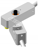 On/Off joint | Expression: [AZ(1,2) × RTOD > 180°] AZ(1,2): Angle between 1 and 2 (1: body 1, 2: body 2) RTOD: Radian to degree 180°: Latching angle |
| Panel 1 | Panel 2 | |
|---|---|---|
| Mass [kg] | 4.23 | 4.28 |
| Moment of inertia [kg∙mm2] w.r.t. C.G. | ||
| Dimension | 800 mm × 800 mm × 20 mm | |
| Test-ID | Joint O | Joint I | Truss-Links |
|---|---|---|---|
| Case 1 | 2.17 N·m (2ea) | 2.38 N·m (2ea) | × |
| Case 2 | 2.17 N·m (2ea) | 2.38 N·m (2ea) | O |
| Case 3 | 2.17 N·m (2ea) | 3.57 N·m (3ea) | O |
| No. | Design Variables | Response Variables | |||
|---|---|---|---|---|---|
| EFT1 | EFT2 | EFT3 | Trajectory Error 1 (%) | Trajectory Error 2 (%) | |
| 1 | 1.17 | 0.60 | 0.10 | 28.65 | 20.75 |
| 2 | 0.75 | 1.10 | 0.10 | 15.90 | 28.03 |
| 3 | 0.75 | 0.60 | 0.10 | 16.32 | 13.07 |
| 4 | 1.00 | 0.30 | 0.15 | 25.69 | 15.20 |
| 5 | 0.33 | 0.60 | 0.10 | 15.49 | 13.32 |
| 6 | 0.75 | 0.095 | 0.10 | 25.35 | 3.66 |
| 7 | 0.50 | 0.90 | 0.05 | 11.10 | 22.03 |
| 8 | 1.00 | 0.30 | 0.05 | 23.98 | 8.73 |
| 9 | 1.00 | 0.90 | 0.05 | 24.64 | 21.46 |
| 10 | 0.50 | 0.30 | 0.05 | 18.07 | 6.70 |
| 11 | 0.75 | 0.60 | 0.016 | 19.46 | 13.29 |
| 12 | 0.50 | 0.30 | 0.15 | 20.60 | 10.84 |
| 13 | 1.00 | 0.90 | 0.15 | 24.64 | 25.36 |
| 14 | 0.75 | 0.60 | 0.18 | 20.28 | 15.88 |
| 15 | 0.50 | 0.90 | 0.15 | 13.71 | 28.34 |
| Test-ID | Driving Torque Energy [N∙m] | Resistance Torque Energy [N∙m] |
|---|---|---|
| Case 1 | 2.818 | 0.848 |
| 4.484 | 1.473 | |
| Case 2 | 2.818 | 0.848 |
| 4.484 | 1.476 | |
| Case 3 | 2.818 | 0.848 |
| 6.726 | 1.476 |
| Test-ID | Joint | Driving Torque [N∙m] | Friction Torque [N∙m] | Torque Margin [%] | Test (Pass/Fail) | Analysis (Pass/Fail) |
|---|---|---|---|---|---|---|
| Case 1 | Joint O | 2.17 | 0.54 | 232.31 | Pass | Pass |
| Joint I | 2.38 | 0.47 | 204.41 | Pass | Pass | |
| Case 2 | Joint O | 2.17 | 0.54 | 232.31 | Pass | Pass |
| Joint I | 2.38 | 0.47 | 203.80 | Pass | Pass | |
| Case 3 | Joint O | 2.17 | 0.54 | 232.31 | Pass | Pass |
| Joint I | 3.57 | 0.47 | 355.69 | Pass | Pass |
Publisher’s Note: MDPI stays neutral with regard to jurisdictional claims in published maps and institutional affiliations. |
© 2022 by the authors. Licensee MDPI, Basel, Switzerland. This article is an open access article distributed under the terms and conditions of the Creative Commons Attribution (CC BY) license (https://creativecommons.org/licenses/by/4.0/).
Share and Cite
Choi, H.-S.; Kim, D.-Y.; Park, J.-H.; Lim, J.H.; Jang, T.S. Modeling and Validation of a Passive Truss-Link Mechanism for Deployable Structures Considering Friction Compensation with Response Surface Methods. Appl. Sci. 2022, 12, 451. https://doi.org/10.3390/app12010451
Choi H-S, Kim D-Y, Park J-H, Lim JH, Jang TS. Modeling and Validation of a Passive Truss-Link Mechanism for Deployable Structures Considering Friction Compensation with Response Surface Methods. Applied Sciences. 2022; 12(1):451. https://doi.org/10.3390/app12010451
Chicago/Turabian StyleChoi, Han-Sol, Dong-Yeon Kim, Jeong-Hoon Park, Jae Hyuk Lim, and Tae Seong Jang. 2022. "Modeling and Validation of a Passive Truss-Link Mechanism for Deployable Structures Considering Friction Compensation with Response Surface Methods" Applied Sciences 12, no. 1: 451. https://doi.org/10.3390/app12010451
APA StyleChoi, H.-S., Kim, D.-Y., Park, J.-H., Lim, J. H., & Jang, T. S. (2022). Modeling and Validation of a Passive Truss-Link Mechanism for Deployable Structures Considering Friction Compensation with Response Surface Methods. Applied Sciences, 12(1), 451. https://doi.org/10.3390/app12010451


