Article

Study on Load Transfer Mechanism of Pile-Supported Embankment Based on Response Surface Method

1
State Key Laboratory of Mechanical Behavior and System Safety of Traffic Engineering Structures, Shijiazhuang Tiedao University, Shijiazhuang 050043, China
2
School of Traffic and Transportation, Shijiazhuang Tiedao University, Shijiazhuang 050043, China
3
School of Civil Engineering, Hebei University of Science and Technology, Shijiazhuang 050018, China
4
School of Civil Engineering, Shijiazhuang Tiedao University, Shijiazhuang 050043, China
5
Hebei Transportation Research Institute, Shijiazhuang 050035, China
*
Author to whom correspondence should be addressed.
Appl. Sci. 2022, 12(10), 4905; https://doi.org/10.3390/app12104905
Submission received: 27 April 2022 / Revised: 10 May 2022 / Accepted: 10 May 2022 / Published: 12 May 2022

Abstract

:
Based on the improved three-dimensional finite element model, this paper studies the load transfer mechanism of pile-supported reinforced embankments. The model uses an elastic medium to replace the soft soil subgrade, which reduces the calculation depth of the subgrade and improves the calculation efficiency of the model. The validity of the model is proven by field test results and theoretical calculation results. By changing the cohesion, internal friction angle, elastic modulus of the embankment filler, and geogrid strength, the effects of various influencing factors on the pile–soil stress ratio, the load-sharing ratio of the soil arching effect, and the load-sharing ratio of the membrane effect was analyzed, and the sensitivity of each influencing factor was evaluated. Based on the response surface optimization test, the multiple regression equation of influencing factors and evaluation indicators was established. The interaction between the parameters was analyzed, and the optimal combination of parameters was solved. The results show the following: Increasing the cohesion, the internal friction angle, and the elastic modulus of the embankment filler can promote the soil arching effect to a certain extent. However, for reinforced embankments, a large cohesion, a large internal friction angle, and a high elastic modulus of an embankment will reduce the pile–soil differential settlement and the pile–soil stress ratio; an increase in geogrid strength has a certain promoting effect on the pile–soil stress ratio. When the geogrid strength reaches 120 kN/m, the pile–soil stress ratio tends to be stable; the tested regression model can accurately reflect the changes in the relationship between the influencing factors and the response values, and it fits the actual situation well. Numerical simulation results show that the optimized pile–soil stress ratio increases by 13.4%.

1. Introduction

Pile-supported reinforced embankments are complex geotechnical structures composed of foundations, piles, pile caps, reinforced cushions, and filled embankments. Through the soil arching effect and the membrane effect, most of the load is transferred to the pile, effectively controlling the embankment settlement. In recent years, many scholars have studied the load transfer mechanism of pile-supported reinforced embankments.
In a study on the calculation method of the load transfer, Hewlett and Randolph [1] considered the soil arch to be a hemispherical shell and split it into one spherical soil arch and four plane soil arches. This model was adopted by the British standard, BS 8006-1 [2]. Zeaske and Kempfert [3] proposed a multi-arch model, which assumed that soil arches are a system composed of a series of spherical shell elements with different centers and different radii. Chen Yun-min et al. [4] modified the Hewlett and Randolph model and introduced a coefficient, α, to determine whether the soil has entered a plastic state. Carlsson [5] proposed a wedge-shaped soil arch model with a top angle of 30°, assuming that the load acting on the soil between piles is equal to the weight of the wedge under any embankment height. This model was adopted by the Nordic Geotechnical Group [6]. On the basis of the Hewlett and Randolph model, as well as the Zeaske and Kempfert model, S.J.M. van Eekelen et al. [7] proposed the concentric arch model. Jones [8] assumed that the deformation curve of reinforcements under a vertical load follows a catenary distribution and deduced the calculation formula of reinforcement tension. Low [9] assumed that the deformation shape of reinforcements is a circular arc and deduced the calculation formula of reinforcement tension. Carlsson [5] proposed a simplified method to calculate the maximum deflection and tension of reinforcements in a two-dimensional plane based on the wedge-shaped soil arch model; on that basis, Rogbeck [10] added a correction coefficient while considering the three-dimensional effect. Li Bo [11] simulated the settlement form of reinforcements between two piles by a plane arc and simulated the deformation mode of reinforcements between four piles by a three-dimensional spherical equation. Xu Chao [12] studied the strain and force characteristics of bars in a three-dimensional state. Because of the different assumptions about the shape of soil arches and the deformation of reinforcements in pile-supported reinforced embankments, there are differences between the calculation methods.
In researching the load transfer mechanism, Chen Fuquan [13] considered the effect of the interfacial friction between the reinforcement and the soil, and used the Winkle elastic foundation model to simulate the foundation soil and analyze the load transfer law. Shunlei Hu [14] proposed a new design method for geogrid-reinforced piled embankments. The method was based on the soil arching effect and the membrane effect, and bearing capacity of the subsoil was considered. Rui [15] studied the effect of different embankment heights and reinforcement stiffness on the load transfer. Bao Ning [16,17] analyzed the embankment load and deformation response by changing the embankment height, the net pile spacing, the internal friction angle of the filler, and the porosity. Han-jiang Lai [18,19] studied the influence of embankment filler properties, embankment height, and pile spacing on the soil arching effect through the discrete element model. Xu Chao [20] showed, through model tests, that the load transfer efficacy could be improved by increasing the cohesion of the embankment filler and reducing the pile spacing. Cao Wei Ping [21] and Chen Yun-min [22] also used model tests to study the influence of pile–soil relative displacement, embankment height, and horizontal reinforcement on the soil arching effect. Through field tests, Liu [23], Wachman [24], and Briancon [25] monitored geogrid deformation, pore water pressure, the settlement of piles and soil between piles, and the lateral displacement of foundations. On this basis, the load transfer mechanism and settlement deformation law were analyzed. The above research on the load transfer law mainly analyzed its influence on the load transfer by changing a single variable. Due to the single evaluation index, it was impossible to clarify the embankment load transfer law under the influence of various factors, or to determine the contribution of the soil arching effect and the membrane effect to the load transfer.
From the above analyses, it can be seen that the research on the load transfer mechanism of pile-supported embankments still has the following problems: At present, the commonly used load transfer calculation method is, first, to use the relevant theory of the soil arching effect to calculate the load acting on the horizontal reinforcement. Then, the reinforced body is used as the research object for carrying out the force analysis and the deformation calculation. However, the soil arching effect and the membrane effect are interactive. The deformation of the reinforced material depends on the size of the load; that is, the degree of the soil arching effect. However, the existence of reinforced materials will affect the magnitude of differential settlement, and then affect the soil arching effect. Therefore, it is of great significance to clarify the contribution of the soil arching effect and the membrane effect to the load transfer mechanism.
In the study of the load transfer law, the main research method at present is single-factor analysis of each influencing factor, without considering the interaction between various factors. Response surface optimization design can determine the optimal design from a range of design variables under given constraints. Therefore, based on the single-factor test, this paper first clarifies the contribution of the soil arching effect and the membrane effect to the load transfer, as well as the degree of the load transfer under the combined action of the soil arching effect and the membrane effect. The sensitivity of each influencing factor was evaluated. Additionally, based on the response surface optimization test, the multiple regression equation of the influencing factors and the evaluation index was established, the interaction relationship between the embankment filling properties and the grid strength was analyzed, and the optimal parameter combination was solved.

2. Numerical Simulation of Pile-Supported Embankments

2.1. Model Establishment and Parameter Selection

As shown in Figure 1, the test section is located in the bridge-subgrade transition section of the Rongwu Expressway in the Xiongan New Area. The soft soil foundation was treated with a prestressed pipe pile composite foundation. The strength of the prestressed pipe pile concrete was C60, the pile length was 14 m, the pile diameter was 0.4 m, and the pile spacing was 2 m. The top of the pile was set with a C30 square-reinforced concrete pile cap of 1.0 m × 1.0 m × 0.3 m. The cushion thickness of the test section was 0.3 m; it was a geogrid-reinforced gravel cushion.
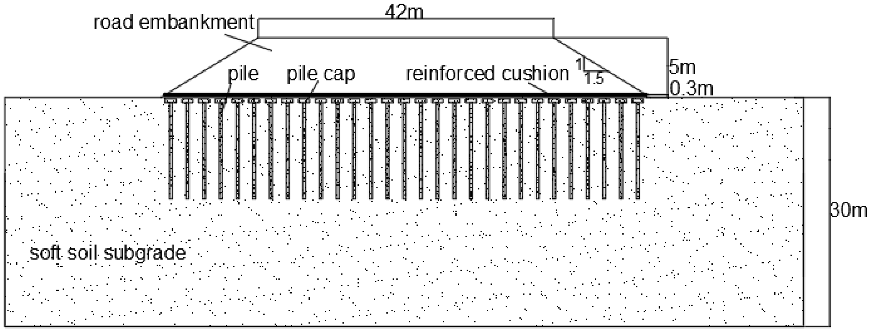
The dimensions of the pile-supported embankment are shown in Figure 2. The width of the subgrade surface was 42 m, and the slope ratio was 1:1.5. The soft soil of the foundation was continuously distributed, with a depth of 30 m. The thickness of the cushion was 0.3 m, the height of the embankment was 5 m, and the embankment was filled in layers.
In order to improve the calculation efficiency of the model, an elastic medium was used to replace the soft soil subgrade to reduce the calculation depth of the subgrade. The properties of the embankment filler and the geogrid strength in the numerical simulation were consistent with the field test conditions. The Mohr–Coulomb model was adopted for embankment materials, and the linear elastic model was adopted for piles and reinforcements; the parameters are shown in Table 1. The material parameters of piles, reinforcements, cushions, and embankment fillers were derived from laboratory tests. The material parameters of the soft soil foundation were inversely deduced by finite element software according to the deformation of the subgrade in the field test. The interaction between the geogrid and embankment filler was simulated by normal hard contact and tangential “penalty” contact. The contact friction angle between the geogrid and embankment was the same as the internal friction angle of the embankment filler [26].

2.2. Boundary Conditions and Mesh Division

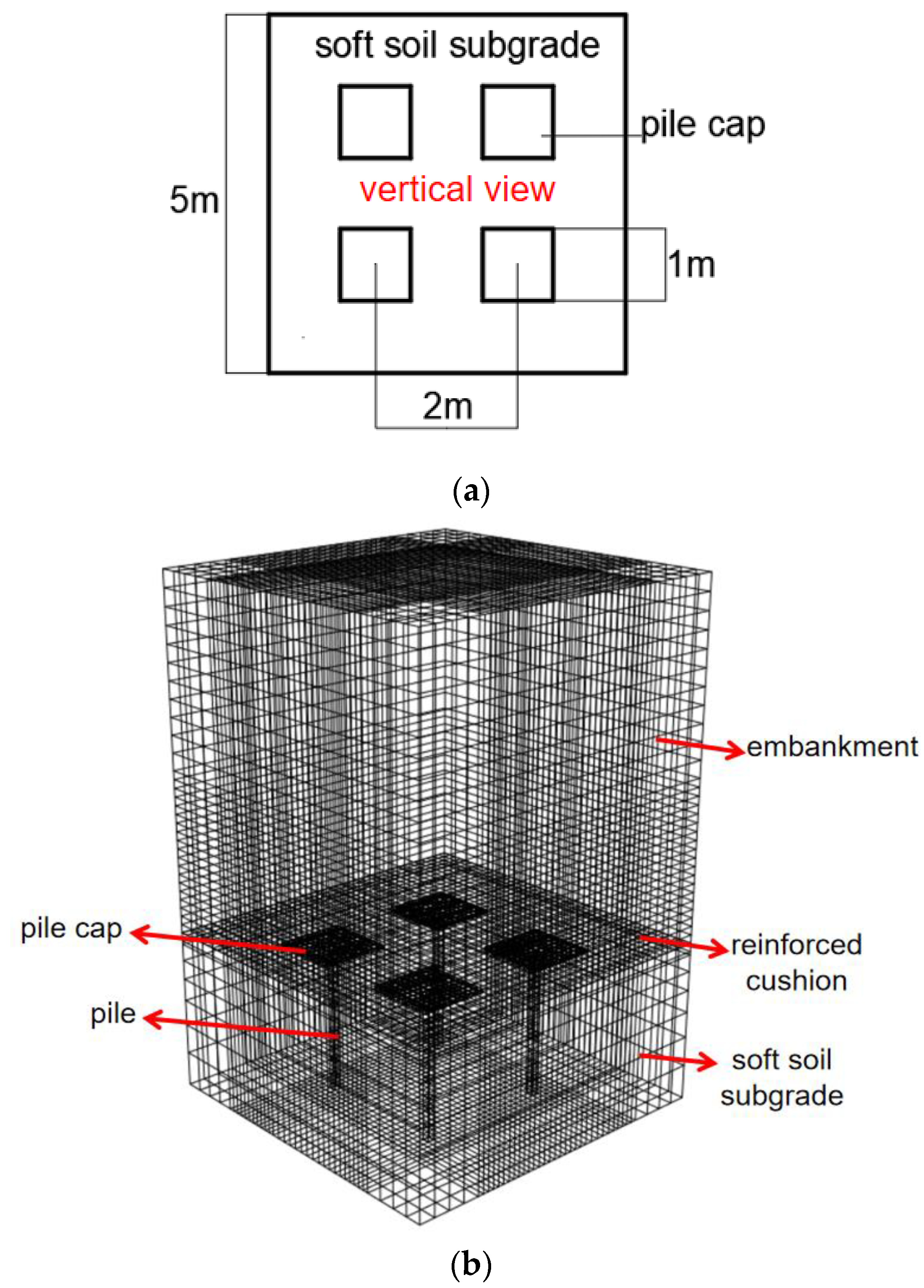
In this paper, a three-dimensional finite element model was established using the finite element software ABAQUS. As shown in Figure 3, four piles were selected as the research units to reduce the influence of artificial boundaries on the internal lateral deformation of the model. Considering the mesh division and the symmetry of the results, under the principle of an equivalent area, square piles were used instead of circular piles. The diameter of the circular pile was 0.4 m, so the side length of the square pile was about 0.35 m. The cushion thickness of the model was 0.3 m, and the embankment height was 5 m. It was filled in 21 layers, and the filling height of each layer, except the cushion, was 0.25 m. In order to explore the internal load transfer law of the embankment, the influence of the embankment slope was ignored, and only the internal filler part was established in the model. In order to improve the calculation efficiency of the model, the soil between piles was simulated by elastic materials, and the pile length was equal to the subgrade height. The bottom constrained the displacement in three directions, x, y, and z, and the horizontal displacement was constrained around the model. In the numerical model, the element type of the embankment, the pile, and the subgrade was C3D8, and the element type used by the geogrid was M3D4.

2.3. Model Verification

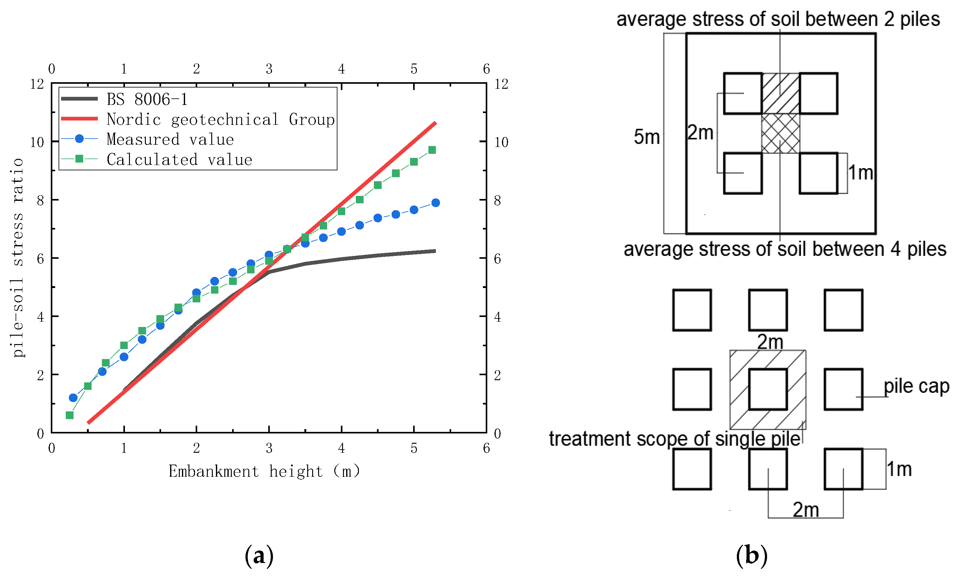
As shown in Figure 4a, in order to verify the accuracy of the model, the calculated values of the model were compared with the measured results of the field test. It can be seen that the calculated value of the pile–soil stress ratio is basically the same as the measured value. When the embankment height was greater than 3.5 m, the calculated value of the model was greater than the measured value. The main reason for this is that there are many uncontrollable factors in the field test, so it was impossible to accurately measure the average stress of the soil between the piles and the top of the pile cap. With the increase in the embankment filling height, the stress concentration effect gradually increased, so the difference between the measured value and the calculation gradually increased. In the model calculation, in order to ensure the accuracy of the data, the average stress of the soil between the piles and the top of the pile cap was calculated in different regions. As shown in Figure 4b, according to the pile spacing, the treatment scope of a single pile could be calculated, and the calculation Formula (1) of the pile–soil stress ratio, n, could be obtained by conversion.
n = σ p σ s σ s = σ s 4 + 2 σ s 2
In the equations: σ p is the average stress at the top of the pile cap, σ s is the average stress of the soil between piles within the single-pile treatment scope, σ s 2 is the average stress of the soil between two piles, and σ s 4 is the average stress of the soil between four piles. The theoretical value of the model was calculated according to BS 8006-1 [2] and the Nordic Geotechnical Group [6]. Since the theoretical basis of each specification was different, the obtained theoretical values were different. By comparison, it can be seen that the variation trend of the calculated value and the theoretical value was basically the same. This proved the rationality of the model.
Figure 4. Analysis of numerical simulation results: (a) model validation; (b) calculation diagram of pile-soil stress ratio.
Applsci 12 04905 g004

3. Analysis of the Numerical Simulation Results

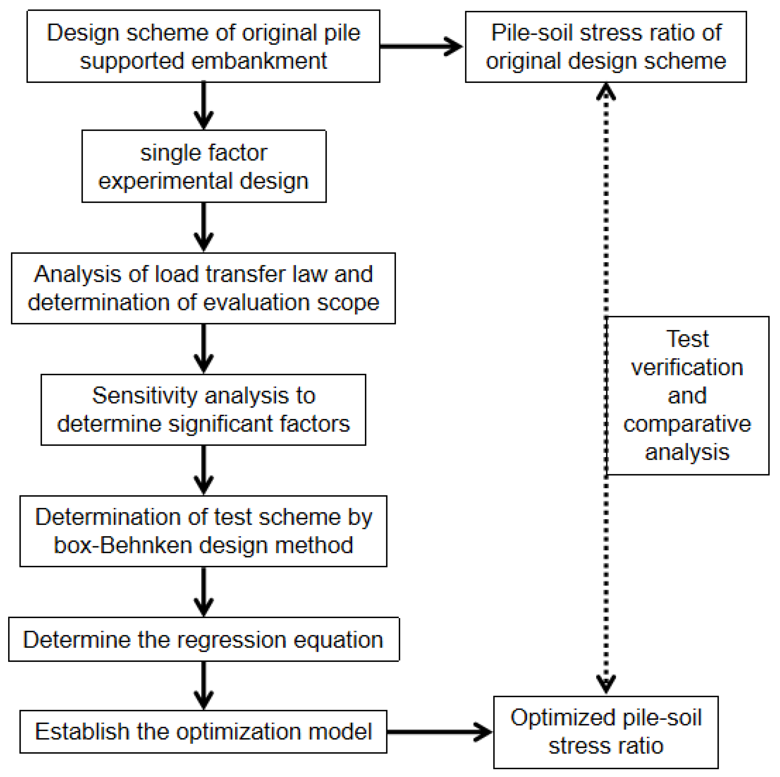
The properties of embankment fillers and the strength of the geogrid of pile-supported embankments were taken as the optimization objects. The pile–soil stress ratio was optimized by combining the ABAQUS numerical simulation calculation and the response surface method. The specific process is shown in Figure 5.

3.1. Single-Factor Test and Results Analysis

The design parameters of model 1 are consistent with the field test, so on the basis of model 1 the cohesion, the internal friction angle, and the elastic modulus of embankment fillers and the geogrid strength were changed, respectively, as a comparison model. In order to analyze the influence of various influencing factors on the pile–soil stress ratio, the load-sharing ratio of the soil arching effect and the load-sharing ratio of the membrane effect were utilized. The geometric parameters of each factor in the single-factor test are shown in Table 2.

3.1.1. Cohesion

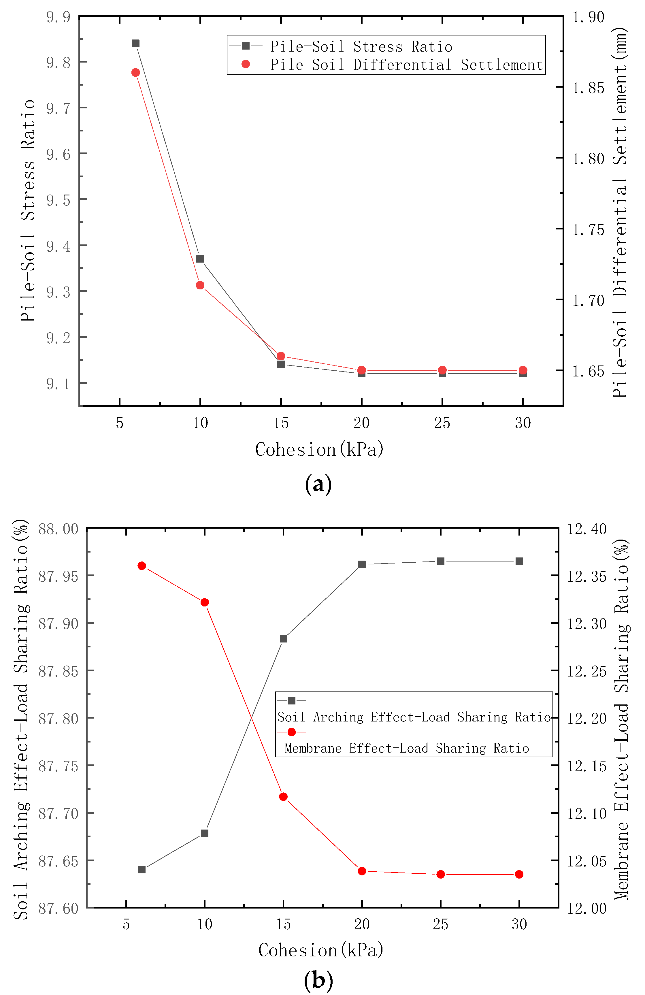
As shown in Figure 6a, with the increase in the cohesion of embankment fillers, the pile–soil stress ratio decreased gradually. When the cohesion was greater than 20 kPa, the pile–soil stress ratio tended to be stable. The variation law of the pile–soil differential settlement was basically the same as that of the pile–soil stress ratio.
The pile-supported reinforced embankment transferred the embankment load to the pile through the combined action of the soil arching effect and membrane effect. The soil arching effect was essentially due to the stress redistribution caused by the pile–soil differential settlement, but the change in the differential settlement affected the exertion of the membrane effect. In order to clarify the proportion of the load shared by the soil arching effect and the membrane effect in the process of the embankment load transfer, the earth pressure at the top and bottom of the geogrid at the top of the pile cap was extracted. The difference between the earth pressure on the upper part of the geogrid and the filling earth pressure was the load transfer caused by the soil arching effect, and the pressure difference between the lower part and the upper part of the geogrid was the load transfer caused by the membrane effect. After data processing, the development law of the load-sharing ratio of the soil arching effect and the membrane effect could be obtained. As shown in Figure 6b, when the cohesion is 5–20 kPa, the degree of the soil arching effect increased rapidly with the increase in the cohesion, and when the cohesion was greater than 20 kPa, the soil arching effect tended to be stable. The main reason for this was that the soil arching effect is related to the material properties of the embankment filler. Due to the pile–soil differential settlement, a shear surface appeared inside the soil, and the greater the cohesion, the greater the shear stress. Therefore, the greater the proportion of the embankment load above the soil between the piles that is transferred to the pile cap. That is, the degree of soil arching effect increases. In Figure 6a, it can be seen that with the increase in the cohesion, the pile–soil differential settlement decreased gradually. The shear deformation between the top embankment filler on the pile cap and the top embankment filler between the piles was reduced. Therefore, the shear stress decreased and the load sharing ratio of the soil arching effect tended to be stable. In addition, the reduction in the pile–soil differential settlement limited the exertion of the membrane effect to a certain extent. Therefore, as shown in Figure 6b, as the cohesion increased gradually, the load-sharing ratio of the membrane effect decreased gradually.
The variation law of the pile–soil stress ratio reflects the load transfer under the combined action of the soil arching effect and the membrane effect. In a comprehensive analysis of the patterns shown in Figure 6a,b, it is seen that with the increase in the cohesion, the soil arching effect increased and the membrane effect decreased, while the pile–soil stress ratio gradually decreased. It can also be seen that the membrane effect was more efficient for the load transfer, i.e., within the same variation range more loads were transferred through the membrane effect.

3.1.2. Internal Friction Angle

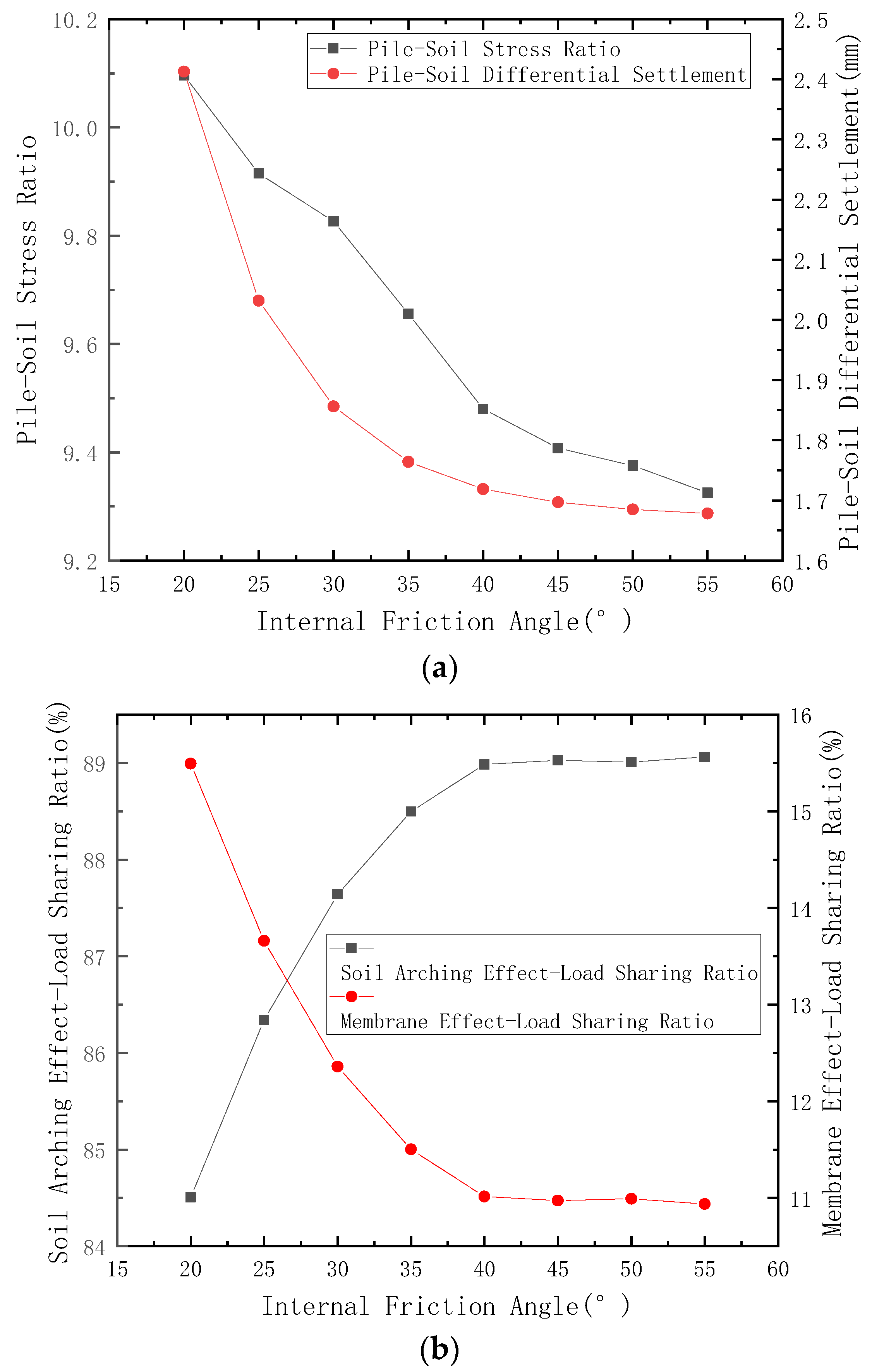
As shown in Figure 7a, when the internal friction angle was 20~40°, the pile–soil stress ratio decreased rapidly with the increase in the internal friction angle of the embankment filler. When the internal friction angle was greater than 40°, the change rate of the pile–soil stress ratio slowed down. The variation law of the pile–soil differential settlement was basically the same as that of the pile–soil stress ratio.
As shown in Figure 7b, when the internal friction angle was 20~40°, with the increase in the internal friction angle, the exertion of the soil arching effect increased rapidly. When the internal friction angle was greater than 40°, the soil arching effect tended to be stable. The main reason for this is that the soil arching effect is essentially a load transfer mechanism caused by the shear stress on the relative sliding surface between embankment fillers. The greater the internal friction angle of the embankment filler, the greater the shear stress on the shear plane; shear stress will transfer more load to the pile, so the load-sharing ratio of the soil arching effect will be greater.

3.1.3. Elastic Modulus of Embankments

As shown in Figure 8a, the pile–soil stress ratio decreased rapidly with the increase in the elastic modulus of the embankment filler, and reached its minimum value when the elastic modulus was 35 MPa. Then, with the increase in the elastic modulus, the pile–soil stress ratio increased slightly. The main reason for this is that the embankment load transfers to the pile under the combined action of the soil arching effect and the membrane effect. As shown in Figure 8b, when the elastic modulus of the embankment was small, the soil arching effect increased and the pulling film effect decreased. Since the membrane effect had higher efficiency for the load transfer, the pile–soil stress ratio decreased gradually when the elastic modulus of the embankment was less than 35 MPa. As the elastic modulus of the embankment continued to increase, the pile–soil differential settlement tended to be stable, so the membrane effect was gradually stable. A larger elastic modulus could promote the soil arching effect. Therefore, when the elastic modulus of the embankment was greater than 35 MPa, the pile–soil stress ratio increased slightly.
As shown in Figure 8b, with the increase in the elastic modulus, the load-sharing ratio of the soil arching effect increased rapidly, and when the elastic modulus was 10–35 MPa the growth rate of the load sharing ratio of the soil arching effect was larger. The main reason for this is that when the elastic modulus of the embankment increases, the load transfer of the embankment mainly comes from two parts: the first part is the shear stress caused by the pile–soil differential settlement of the embankment filler at the top of the pile cap and the top of the soil between the piles; the second part is the connection force between soil particles. The greater the elastic modulus of the embankment filler, the greater the deformation resistance of the embankment, and the higher the integrity.
From the microscopic point of view, this shows greater connection strength between soil particles. When differential settlement occurs on the subgrade surface, the embankment load on the upper soil between piles transfers to the pile cap through the connection force between soil particles. Therefore, with the increase in the elastic modulus, the load sharing ratio of the soil arching effect increased rapidly under the combined action of shear stress and connection force. In contrast, Figure 8a shows that when the elastic modulus was large, the pile–soil differential settlement gradually tended to be stable. The shear deformation between embankment fillers tended to be stable, that is, the load transferred by the shear stress remained basically unchanged. At this time, the load transfer was mainly caused by the connection force between soil particles. Therefore, as the elastic modulus continued to increase, the growth rate of the load sharing ratio of the soil arching effect gradually decreased.

3.1.4. Geogrid Strength

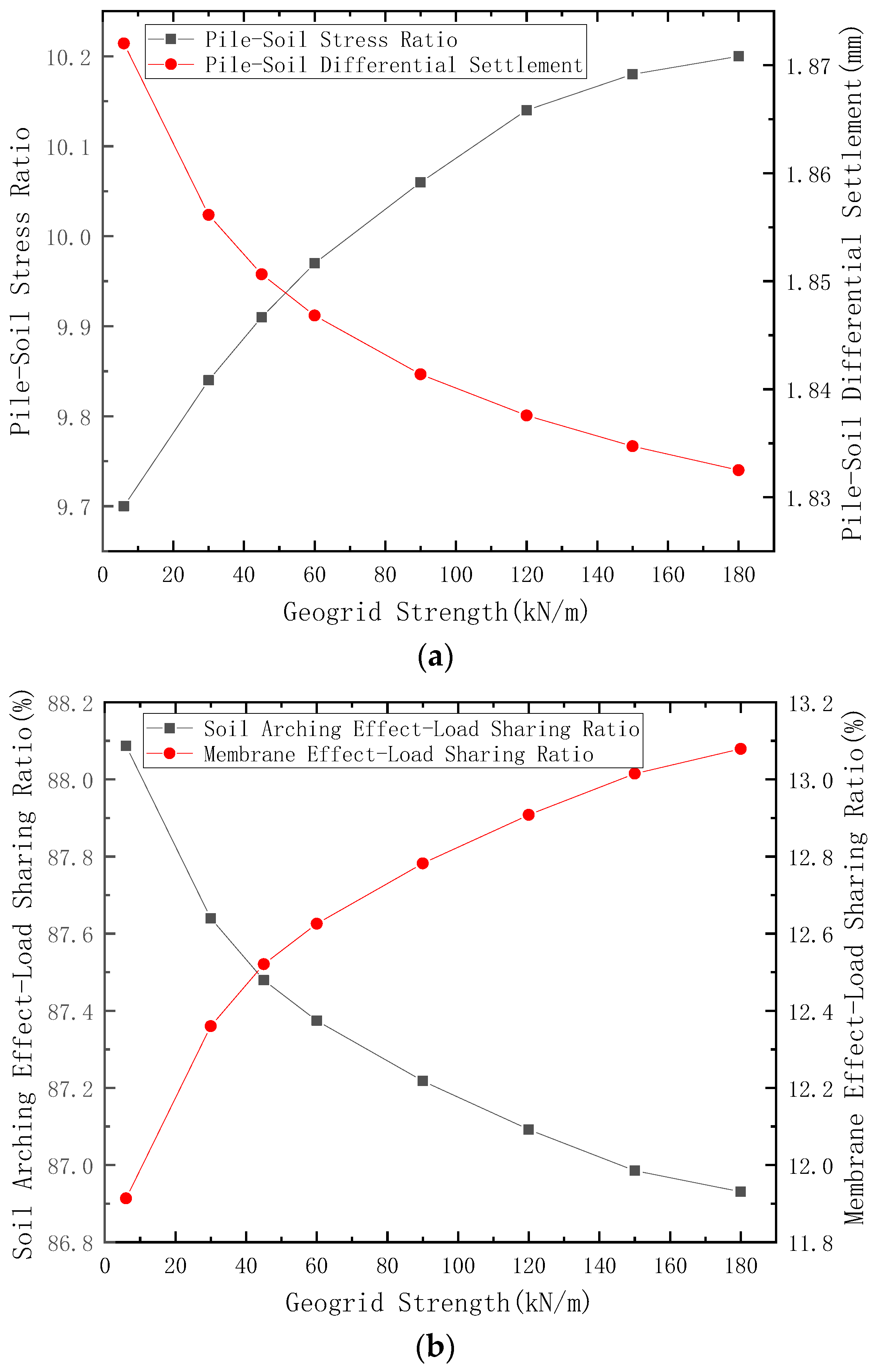
As shown in Figure 9a, with the increase in the geogrid strength, the pile–soil stress ratio gradually increased, but the increasing range gradually decreased. When the geogrid strength reached 120 kN/m, the pile–soil stress ratio did not increase significantly with the increase in the tensile strength. There were two main reasons for this: First, frictional resistance and occlusal force were generated at the interface between the filler particles and geo-reinforced material, which caused tension inside the geogrid and the transfer part of the filler load to the top of the pile; second, the geogrid had a “lifting effect” on the upper soil, and the geogrid shared the vertical load and transferred it to the pile top. Therefore, the setting horizontal reinforcement had a certain promotion effect on the load transfer.
It can be seen from the variation law of the pile–soil differential settlement, as shown in Figure 9a, that although the increase in the grid strength reduced the pile–soil differential settlement to a certain extent, the effect was not obvious. The main reason for this is that the “lifting effect” of the horizontal reinforcement reduces the load on the soil between piles, thereby reducing the settlement of the soil between piles. However, the horizontal reinforcement reduces the differential settlement of piles and soil, which affects the soil arching effect. Therefore, the load borne by the soil between piles increases, and the settlement of the soil between piles increases. Due to the cross-influence of the above reasons, the influence of reinforcement strength on the pile–soil differential settlement was not obvious.
In contrast, Figure 9b shows that with the increase in the geogrid strength, the load sharing ratio of the membrane effect increased gradually, but the growth rate decreased gradually. The reason for this is that, as the pile–soil differential settlement was basically unchanged, the deformation degree of the geogrid was certain. With the increase in the geogrid strength, the vertical component of the geogrid tension increased, so the embankment load on the soil between piles could be reduced. The geogrid strength continued to increase, but other conditions remained unchanged (such as the embankment load and the pile–soil differential settlement). That is, the embankment load balanced by the membrane effect was basically unchanged, so the growth rate of the load-sharing ratio of the membrane effect decreased.
In summary, increasing the cohesion, the internal friction angle, and the elastic modulus of the embankment filler can promote the soil arching effect to a certain extent. However, for pile-supported reinforced embankments, the degree of the load transfer under the combined action of the soil arching effect and the membrane effect was analyzed. Large cohesion, a large internal friction angle, and a high elastic modulus of the embankment reduced the pile–soil differential settlement and the pile–soil stress ratio; the increase in the geogrid strength had a certain promoting effect on the pile–soil stress ratio. However, when the geogrid strength reached 120 kN/m, the increase in the pile–soil stress ratio was small; therefore, in the design of pile-supported embankments, the properties of the embankment filler should be determined according to the reinforcement’s form to ensure that the embankment has a high load transfer efficiency.

3.1.5. Parameter Sensitivity Evaluation

Sensitivity analysis can be used to determine the influence of each influencing factor on the pile–soil stress ratio and to determine the weight of each influencing factor. By changing the size of the influencing factors, the change rule of the evaluation index can be determined. The sensitivity coefficient, SAF, represents the sensitivity of the influencing factors to the evaluation indexes. The larger |SAF| is, the more sensitive the evaluation index, A, is to the influencing factor, F. The calculation equation is as follows:
S A F = i = 1 n Δ A i A 0 Δ F i F 0
where Δ F i / F 0 is the change rate of the influencing factors, %; Δ F i : is the amount of change in the influencing factors; F0 represents the corresponding parameters in model 1; Δ A i / A 0 is the corresponding change rate of the evaluation index, A, when the influencing factor, F, changes in Δ F i ; Δ A i is the amount of change in the evaluation index; and A0 is the value of the evaluation index in model 1.
The evaluation range of each influencing factor was determined by the single–factor test, and the sensitivity coefficient of each influencing factor was calculated, as shown in Table 3. It can be seen that the pile–soil stress ratio is sensitive to the change in the internal friction angle and the elastic modulus of the embankment filling, followed by the cohesion. The geogrid strength had the lowest sensitivity due to its large evaluation range, i.e., when the variation range of the embankment filler properties is small, the pile–soil stress ratio will change significantly, while the pile–soil stress ratio will only be affected when the geogrid strength changes greatly. Therefore, it is suggested that, in the design of pile-supported embankments, in addition to the main design parameters, such as pile length, pile spacing, and grid strength, the influence of embankment filling properties on the load transfer should be considered.

3.2. Response Surface Optimization Test and Results Analysis

3.2.1. Response Surface Test Design

The main variation range of each influencing factor was determined by the single–factor test. Based on the Box–Behnken design method of Design-Expert software, the response surface experimental design was carried out, as shown in Table 4. According to the test design, the total number of tests was twenty-nine, of which twenty-four test points were external analysis and five test points were the center of the region. Center point repeat calculations were used to estimate the experimental error.
Table 5 shows the test design results.
The regression equation of the pile–soil stress ratio can be obtained by fitting the test results with a second-order polynomial. In order to further optimize the regression equation, the insignificant items in the variance analysis can be removed and refitted.
The optimized pile–soil stress ratio regression equation is as follows:
n = 9.30 − 0.24A − 0.033B + 0.056C + 0.089D + 0.078AB + 0.14AC + 0.26A2 + 0.14C2
To ensure the accuracy and adaptability of the model, its predictive ability needed to be evaluated. For the significance test of the response surface equation, the correlation coefficient, R2, and the determination coefficient, R a d j 2 , were generally used to express its approximation degree.
R 2 = S R S T = S T S E S T = 1 S E S T S T = i = 1 n y i y ¯ 2 S E = i = 1 n y y i 2
where ST is the total sum of the squares; SR is the regression sum of the squares; SE is the residual sum of the squares; y ¯ is the mean of the response values; and y is the predicted value of the response value. The correlation coefficient, R2, is a measure of complete fit, reflecting the degree of conformity between the response surface and the experimental data; R2 is greater than 0.9 to ensure the fitting effect:
R a d j 2 = 1 S E / n n p 1 S T / n 1 = 1 n 1 n p 1 ( 1 R 2 )
where n is the sample size, and np is the number of optimization variables. The determination coefficient, R a d j 2 , represents the correlation between the independent variables and dependent variables, and the closer the value is to 1, the better the fitting effect is.
The results of the variance analysis of the fitted regression equation are shown in Table 6. The value of Prob(P) > F of the regression equation of the pile–soil stress ratio was less than 0.0001, indicating that the model is highly significant. This shows that the equation can accurately reflect the relationship between the evaluation index and each influencing factor. The fact that the regression equation correlation coefficient, R2 = 0.959, was greater than 0.9 shows that the orthogonal experimental results and mathematical model fit well, and that the mathematical model can be used to infer the experimental results. The determination coefficient, R a d j 2 = 0.943, indicated that 94.3% of the data can be explained by this equation, and the higher fitting degree can be used to predict the pile–soil stress ratio. The coefficient of variation, CV, reflects the confidence of the model. The smaller the CV, the higher the confidence of the model. When the CV is less than 10, it is considered that the reliability of the test is higher. Precision reflects the accuracy of the model, and generally requires that the precision of the model should be greater than 4. The precision of the coefficient of variation, CV = 0.598, of the pile–soil stress ratio regression equation was 26.784, showing that the reliability and accuracy of the test are high, and that the regression equation obtained by fitting is meaningful and can be used to predict the pile–soil stress ratio of the pile-supported embankment.

3.2.2. Analysis of the Interaction between Parameters

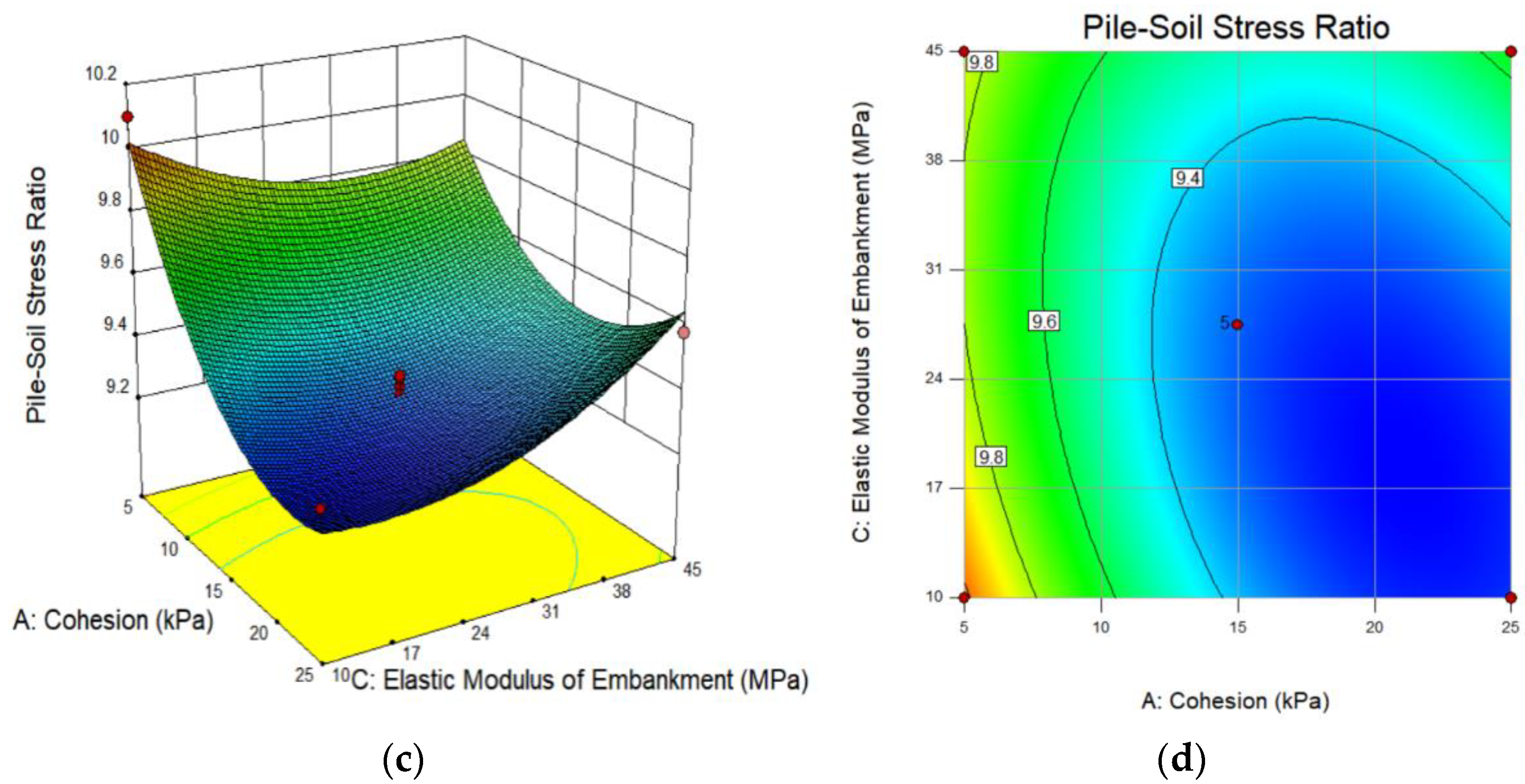
The pile–soil stress ratio was used as the main inspection index with which to study the mechanical properties of pile-supported embankments. The variation trend under the interaction of various parameters affecting the pile–soil stress ratio is shown in Figure 8. The parameters included the cohesion, A, the internal friction angle, B, the embankment elastic modulus, C, and geogrid strength, D.
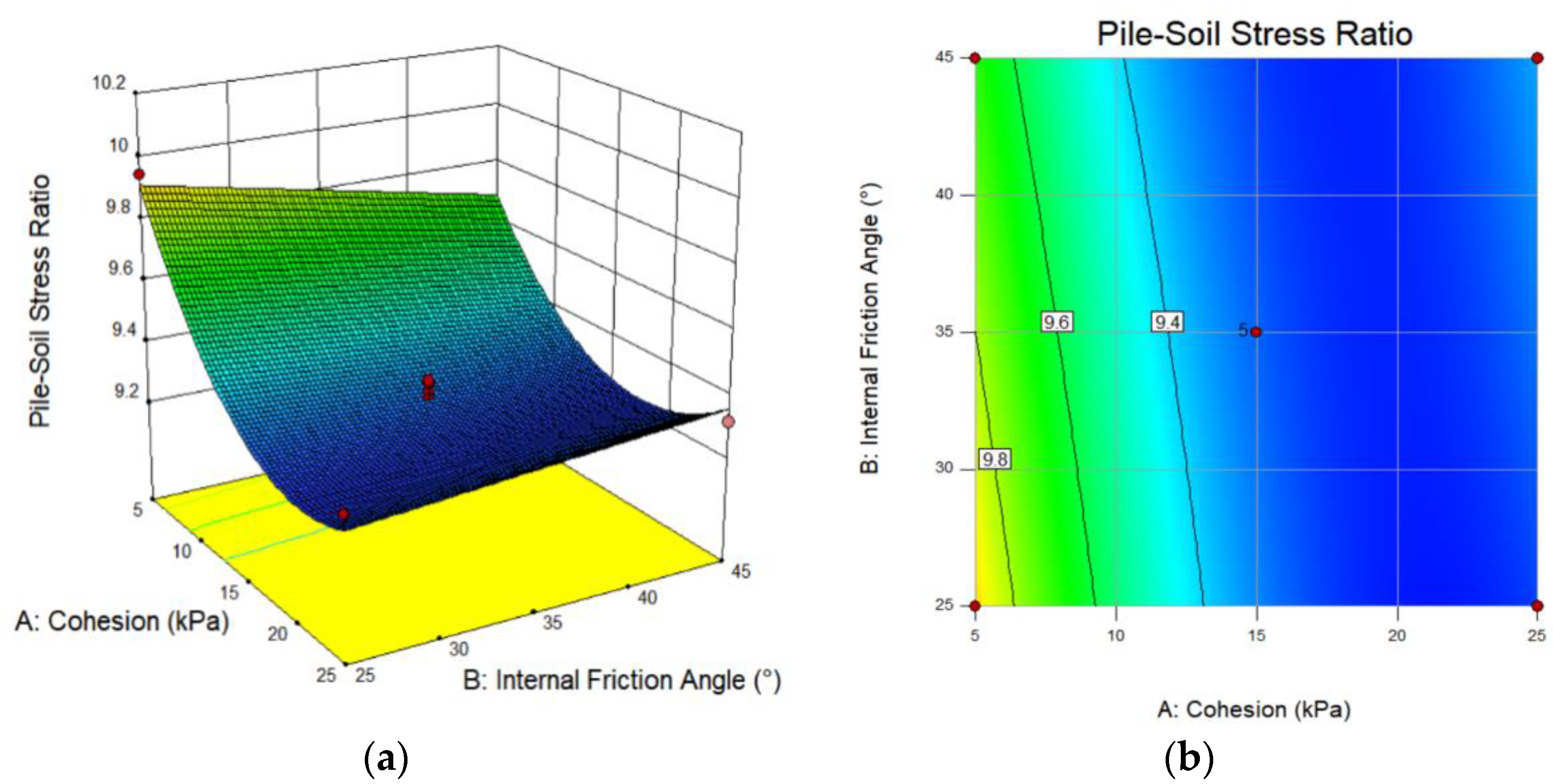
From the regression equation of the pile–soil stress ratio, it can be seen that the interaction terms affecting the pile–soil stress ratio are AB and AC. From the variation of the influencing factors, in the evaluation range, the pile–soil stress ratio gradually decreased and tended to be stable with the increase in cohesion. When the cohesion was greater than 15 kPa, the pile–soil stress ratio was basically unchanged; when the internal friction angle increased, the pile–soil stress ratio decreased, and the relationship between them was basically linear; when the elastic modulus of the embankment increased, the pile–soil stress ratio decreased; and when the elastic modulus was 24–38 MPa, the pile–soil stress ratio reached its minimum. If the elastic modulus continued to increase, the pile–soil stress ratio increased slightly.
It can be seen from Table 6 that the Prob(P) value of AB was 0.0118, indicating that the difference of AB is significant. The Prob(P) value of AC was less than 0.0001, indicating that the difference of AC is extremely significant. In addition, the contour line presents an ellipse with large curvature, indicating that the interaction is significant. As shown in Figure 10b,d, the slope of the response surface of the cohesion and embankment elastic modulus was relatively slow, and the contour line presented an ellipse with small curvature. However, the response surfaces of the cohesion and the internal friction angle are saddle-shaped, with large slopes. Therefore, from the perspective of interaction, the combination of the cohesion and internal friction angle had a great influence on the test results.

3.2.3. Validation of Response Surface Optimization Results

The regression Equation (3) was solved with the maximum pile–soil stress ratio. The optimal solution of the embankment filling parameters and grid strength could be obtained. Its parameters were a cohesion of 5 kPa, an internal friction angle of 25.076°, an embankment elastic modulus of 10 MPa, and a geogrid strength of 117.749 kN/m. In order to consider the convenience of construction, the internal friction angle was 25°, the grid strength was 120 kN/m, and the parameters were taken as the recommended values of the response surface optimization results, as shown in Table 7. The error between the prediction results of the response surface and the calculated values of the optimized model was 6.79%, indicating that the regression equation had a good fitting degree.
According to the parameters before and after optimization, the pile–soil stress ratio was calculated and compared in ABAQUS, as shown in Figure 11. The pile–soil stress ratio was 9.7 under the initial design, and the optimized pile–soil stress ratio was 11. Compared with the original design, the optimized pile–soil stress ratio increased by 13.4%. It can be seen that the optimized model can significantly promote the load transfer.

4. Conclusions

Based on the improved three-dimensional finite element model, this paper analyzed and compared the influence of the embankment filler properties and geogrid strength on the load transfer. Firstly, based on the single-factor test, the contribution of the soil arching effect and membrane effect to the load transfer, as well as the variation law of the pile–soil stress ratio under embankment load, were clarified. Then, based on the response surface optimization test, the interactive relationship between the embankment filler properties and the geogrid strength was analyzed, and the original design was optimized. The results showed that:
(1)
Using an elastic medium instead of a soft soil subgrade can reduce the calculation depth of the subgrade and improve the calculation efficiency of the model. The calculated values of the model were in good agreement with the measured results of the field test. The theoretical value of the model was calculated according to BS 8006-1 and the Nordic Geotechnical Group, and the change trend of the calculated value, as well as the theoretical value, were basically the same. This proved the rationality of this model.
(2)
Increasing the cohesion, the internal friction angle, and the elastic modulus of embankment filler can promote the soil arching effect to a certain extent. However, for reinforced embankments, larger cohesion, a larger internal friction angle, and a higher elastic modulus of the embankment will reduce the pile–soil differential settlement, affecting the load transfer and reducing the pile–soil stress ratio.
(3)
The increase in the geogrid strength had a certain promoting effect on the pile–soil stress ratio. However, when the geogrid strength reached 120 kN/m, the increase in the pile–soil stress ratio was small.
(4)
The pile–soil stress ratio was more sensitive to the changes of the internal friction angle of the embankment filler and the elastic modulus of the embankment, followed by the cohesion. The sensitivity of the geogrid strength was the lowest. Therefore, it is suggested that in the design of pile-supported embankments, in addition to the main design parameters, such as pile length, pile spacing, and grid strength., the influence of embankment filling properties on the load transfer should be considered.
(5)
The Box–Behnken design method was used for the experimental design, and the multiple regression model, considering the pile–soil stress ratio, was established. The variance analysis was used to test the fitting degree of the model. The results showed that the regression model can accurately reflect the change relationship between the influencing factors and response values, and that it is well-fitted to the actual situation.
(6)
The optimal parameter combination of the maximum pile–soil stress ratio was obtained by establishing a multiple regression equation. The numerical simulation results showed that the pile–soil stress ratio increased by 13.4%.
In summary, in this paper, a load transfer analysis method of embankments, considering the combined action of multiple factors, was proposed, to accurately calculate the pile–soil stress ratio under the embankment load. The change of embankment filling properties and geogrid strength will affect the degree of the soil arching effect and membrane effect, and the transfer efficiency of the soil arching effect and membrane effect on load is different. Therefore, in the design of pile-supported embankments, the reinforcement form of embankments should be determined first, and then the nature of embankment fillers should be determined to ensure that the design has a high load transfer efficiency.

Author Contributions

Writing—original draft preparation, X.W. (Xin Wang); writing—review, X.W. (Xizhao Wang); funding acquisition, G.Y.; validation, Y.Z. All authors have read and agreed to the published version of the manuscript.

Funding

This research was supported by the National Natural Science Foundation of China (Grant No.52079078); the Key R&D Projects in Hebei Province (Grant No.20375504D); the Hebei Provincial Department of Transportation Science and Technology Project (Grant No.RW-202014); and the Innovation Funding Project for Postgraduates in Hebei Province (Grant No. CXZZBS2022121).

Data Availability Statement

The data used to support the findings of this study are available from the corresponding author upon request.

Conflicts of Interest

The authors declare no conflict of interest.

References

  1. Hewlett, W.J.; Randolph, M.F. Analysis of piled embankment. Ground Eng. 1988, 21, 12–18. [Google Scholar]
  2. BS 8006-1; 2010 Code of Practice for Strengthened/Reinforced Soils and Other Fills. British Standards Institution: London, UK, 2010.
  3. Zaeske, D.; Kempfert, H.G. Calculation and mechanism of unreinforced and reinforced base layers on point and line-shaped support members. Civ. Eng. 2002, 77, 80–86. [Google Scholar]
  4. Yun-Min, C.; Ning, J.I.A.; Ren-Peng, C. Soil arch analysis of pile-supported embankment. China J. Highw. Transp. 2004, 17, 4–9. [Google Scholar]
  5. Carlsson, B. Reinforced Soil, Principles for Calculation; Terratema AB: Linöping, Sweden, 1987. [Google Scholar]
  6. Nordic Geotechnical Group. Nordic Guidelines for Reinforced Soils and Fills; Nordic Geotechnical Group: Stockholm, Sweden, 2004. [Google Scholar]
  7. Van Eekelen, S.J.M.; Bezuijen, A.; Van Tol, A.F. An analytical model for arching in piled embankments. Geotext. Geomembr. 2013, 39, 78–102. [Google Scholar] [CrossRef]
  8. Jones, C.J.F.P.; Lawson, C.R.; Ayres, D.J. Geotextile reinforced piled embankments. In Proceedings of the 4th International Conference on Geotextiles: Geomembranes and Related Products, Rotterdam, The Netherlands, 28 May–1 June 1990; A. A. Balkema: Rotterdam, The Netherlands, 1992; pp. 155–160. [Google Scholar]
  9. Low, B.K.; Tang, S.K.; Choa, V. Arching in piled embankments. J. Geotech. Eng. 1994, 120, 1917–1938. [Google Scholar] [CrossRef]
  10. Rogbeck, Y.; Gusta Vsson, S.; Sodergren, I. Reinforced piled embankments in Sweden-design aspects. In Proceedings of the 1998 Sixth International Conference on Geosynthetics, Atlanta, GA, USA, 25–29 March 1998; pp. 755–762. [Google Scholar]
  11. Bo, L.I.; Mao-Song, H.; Guan-Bao, Y.E. Analysis of Three-dimensional Soil Arching Effect of Pile-supported Embankment with Geosynthetics and Its Test Verification. China J. Highw. Transp. 2012, 25, 13–20. [Google Scholar]
  12. Chao, X.U.; Xiao, L.; Pan-Pan, S. Model tests of tensile membrane effect of geosynthetic-reinforced Piled embankments. Rock Soil Mech. 2016, 37, 182–1831. [Google Scholar]
  13. Chen, F.Q.; Li, A. Improved design method of geosynthetic reinforced pile supported embankments on soft soil. Chin. J. Geotech. Eng. 2007, 29, 1804–1808. [Google Scholar]
  14. Hu, S.; Zhuang, Y.; Zhang, X.; Dong, X. A Design Chart for the Analysis of the Maximum Strain of Reinforcement in GRPEs Considering the Arching and Stress History of the Subsoil. Appl. Sci. 2022, 12, 2536. [Google Scholar] [CrossRef]
  15. Rui, R.; Yi, W.; Cheng, C.; Yan, Z.; Kai, Z. Experimental Investigation on Influences of Geosynthetic Reinforcement on Deformation Pattern and Soil Arching in Piled Embankments. China J. Highw. Transp. 2020, 33, 40–50. [Google Scholar]
  16. Bao, N.; Wei, J.; Chen, J.-F. Three dimensional discrete element analysis of soil arching in piled embankment. Rock Soil Mech. 2020, 41 (Suppl. S1), 347–354. [Google Scholar]
  17. Bao, N.; Wei, J.; Chen, J.F.; Wei, P. 2D and 3D discrete numerical modelling of soil arching. J. Zhejiang Univ.-Sci. A (Appl. Phys. Eng.) 2020, 21, 350–365. [Google Scholar] [CrossRef]
  18. Lai, H.J.; Zheng, J.J.; Zhang, R.J.; Cui, M.J. Visualization of the formation and features of soil arching within a piled embankment by discrete element method simulation. J. Zhejiang Univ.-SCIENCE A (Appl. Phys. Eng.) 2016, 17, 803–817. [Google Scholar] [CrossRef] [Green Version]
  19. Lai, H.J.; Zheng, J.J.; Zhang, J.; Zhang, R.J.; Cui, L. DEM analysis of “soil”-arching within geogrid-reinforced and unreinforced pile-supported embankments. Comput. Geotech. 2014, 61, 13–23. [Google Scholar] [CrossRef]
  20. Xu, C.; Song, S. Scaled Modle Tests of Soil Arching Effect in Geosynthetic Reinforced and Pile Supported Embankments. Chin. J. Rock Mech. Eng. 2015, 34, 4343–4350. [Google Scholar]
  21. Cao, W.; Chen, R.P.; Chen, Y.M. Experimental investigation on soil arching in piled reinforced embankments. Chin. J. Geotech. Eng. 2007, 29, 436–441. [Google Scholar]
  22. Yun-Min, C.; Wei-Ping, C.; Ren-Peng, C. An experimental investigation of soil arching within basal reinforced and unreinforced piled embankments. Geotext. Geomembr. 2008, 26, 164–174. [Google Scholar] [CrossRef]
  23. Liu, H.L.; Ng, C.W.; Fei, K. Performance of a geogrid-reinforced and pile-supported highway embankment over soft clay: Case study. J. Geotech. Geoenviron. Eng. 2007, 133, 1483–1493. [Google Scholar] [CrossRef]
  24. Wachman, G.S.; Biolzi, L.; Labuz, J.F. Structural Behavior of a pile-supported embankment. J. Geotech. Geoenviron. Eng. 2010, 136, 26–34. [Google Scholar] [CrossRef]
  25. Briançon, L.; Simon, B. Performance of pile-supported Embankment over soft soil: Full-scale experiment. J. Geotech. Geoenviron. Eng. 2012, 138, 551–561. [Google Scholar] [CrossRef]
  26. Zhuang, Y.; Ellis, E. Finite-element analysis of a piled embankment with reinforcement compared with BS 8006 predictions. Geotechnique 2014, 64, 910–917. [Google Scholar] [CrossRef]
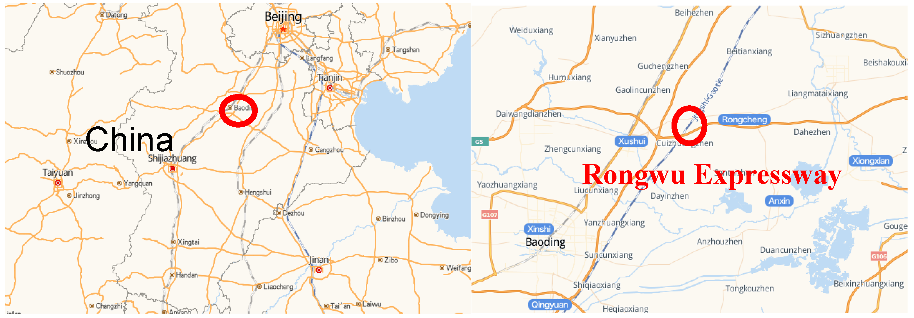
Figure 1. Geographical location of the test site.
Applsci 12 04905 g001
Figure 2. Cross-section of geosynthetic-reinforced piled embankment.
Applsci 12 04905 g002
Figure 3. Three-dimensional finite element model of geosynthetic-reinforced piled embankment: (a) model planar graph; (b) model grid partition diagram.
Applsci 12 04905 g003
Figure 5. Design optimization process of pile-supported reinforced embankment based on response surface method.
Applsci 12 04905 g005
Figure 6. Influence of cohesion on load transfer; (a) variation of pile-soil stress ratio and pile-soil differential settlement; (b) variation law of load sharing ratio.
Applsci 12 04905 g006
Figure 7. Influence of internal friction angle on load transfer. (a) variation of pile-soil stress ratio and pile-soil differential settlement; (b) variation law of load sharing ratio.
Applsci 12 04905 g007
Figure 8. Influence of embankment elastic modulus on load transfer. (a) variation of pile-soil stress ratio and pile-soil differential settlement; (b) variation law of load sharing ratio.
Applsci 12 04905 g008aApplsci 12 04905 g008b
Figure 9. Influence of geogrid strength on load transfer. (a) variation of pile-soil stress ratio and pile-soil differential settlement; (b) variation law of load sharing ratio.
Applsci 12 04905 g009
Figure 10. Interaction between parameters affecting pile-soil stress ratio; (a) response surface of cohesion and internal friction angle; (b) two-dimensional diagram of interaction between cohesion and internal friction angle; (c) response surface of cohesion and elastic modulus of embankment; (d) two-dimensional diagram of interaction between cohesion and elastic modulus of embankment.
Applsci 12 04905 g010aApplsci 12 04905 g010b
Figure 11. Variation curve of pile-soil stress ratio before and after response surface optimization.
Applsci 12 04905 g011
Table 1. Material parameters used in finite element model of piled embankment.
MaterialThickness (Length)
[m]
Volume Weight
[kN/m3]
E
[MPa]
Poisson RatioInternal Friction Angle
[°]
Cohesion
[kPa]
Pile22520,0000.2--
Geogrid--0.50.2--
Cushion0.320200.3376
Embankment518.5150.35306
Soft soil subgrade20.2540.34--
Table 2. Geometric parameters of factors in single factor test.
NO.Cohesion [kPa]Angle of Internal Friction [°]Elastic Modulus of Embankment [MPa]Geogrid Strength [kN/m]Declaration
16301530Model validation
210301530Models 1–6 analyze the effect of cohesion
315301530
420301530
525301530
630301530
76201530Model 1 and models 7–13 analyze the effect of internal friction angle
86251530
96351530
106401530
116451530
126501530
136551530
146301030Model 1 and models 14–21 analyze the effect of embankment elastic modulus
156302030
166302530
176303030
186303530
196304530
206305530
216306530
22630156Model 1 and models 22–28 analyze the effect of geogrid strength
236301545
246301560
256301590
2663015120
2763015150
2863015180
Table 3. Sensitivity coefficient |SAF| of influencing factors.
Influencing FactorEvaluation ScopeSensitivity Coefficient |SAF|
Cohesion [kPa]6–250.175
Internal Friction Angle [°]25–450.253
Elastic Modulus of Embankment [MPa]10–450.24
Geogrid Strength [kN/m]30–1200.048
Table 4. Test design factors and levels.
Influencing FactorsCoding Level
−101
Cohesion A [kPa]21527
Internal Friction Angle B [°]253545
Elastic Modulus of Embankment C [MPa]1027.545
Geogrid Strength D [kN/m]3075120
Table 5. Response surface design test results.
NO.Cohesion A [kPa]Internal Friction Angle B [°]Elastic Modulus of Embankment C [MPa]Geogrid Strength D [kN/m]Pile–Soil Stress Ratio n
1−1−1009.95
21−1009.32
3−11009.63
411009.32
500−1−19.21
6001−19.43
700−119.43
800119.61
9−100−19.66
10100−19.21
11−10019.94
1210019.40
130−1−109.39
1401−109.33
150−1109.51
1601109.52
17−10−1010.10
1810−109.32
19−10109.80
2010109.58
210−10−19.22
22010−19.21
230−1019.33
2401019.32
2500009.32
2600009.30
2700009.35
2800009.29
2900009.36
Table 6. Variance analysis of regression equation.
TypeSum of SquaresDegree of FreedomMean SquareF ValueProb(P) > F
Model1.49680.18758.475<0.0001
Cohesion A0.71510.715223.468<0.0001
Internal Friction Angle B0.01310.0133.9990.0593
Elastic Modulus of Embankment C0.03810.03811.8140.0026
Geogrid Strength D0.09510.09529.687<0.0001
AB0.02510.0257.6810.0118
AC0.07810.07824.270<0.0001
A20.46310.463144.622<0.0001
C20.12810.12839.990<0.0001
Residual0.064200.003
Pure Error0.00440.001
Lack of Fit0.060160.0044.0720.092
Cor Total1.56028
R2 = 0.959   R a d j 2 = 0.943 CV = 0.598 Adeq precision = 26.784
(Note: P < 0.05 indicates significant difference; P < 0.01 indicates extremely significant difference.)
Table 7. Response surface optimization results.
Cohesion [kPa]Internal Friction Angle [°]Elastic Modulus of Embankment [MPa]Geogrid Strength [kN/m]Pile–Soil Stress Ratio n
Original Embankment Design63015309.7
Predict the Optimal Combination525.07610117.74910.3
Optimization Model Verification5251012011
Publisher’s Note: MDPI stays neutral with regard to jurisdictional claims in published maps and institutional affiliations.