Article

Thermal Modeling of Ultrasound Diathermy in Tissues with a Circular Inclusion near a Curved Interface

1
Department of Civil Engineering, Chung Yuan Christian University, Taoyuan City 320314, Taiwan
2
R&D Center for Membrane Technology, Chung Yuan Christian University, Taoyuan City 320314, Taiwan
*
Author to whom correspondence should be addressed.
Appl. Sci. 2022, 12(10), 5166; https://doi.org/10.3390/app12105166
Submission received: 15 April 2022 / Revised: 14 May 2022 / Accepted: 17 May 2022 / Published: 20 May 2022
(This article belongs to the Section Applied Thermal Engineering)

Abstract

:

Featured Application

Pertinent findings may serve as a guide for clinical innovations in therapeutic ultrasounds.

Abstract

The influences of implants on the temperature field in tissues during ultrasound diathermy is controversial. In addition, most previous studies have focused on plate implants, and the effects of irregular implants and bones are seldom discussed. In this study, a hybrid computational framework per se is proposed to investigate the effects of double circular inclusions on the temperature distribution during ultrasound diathermy. The tissue–inclusion–bone structure is simplified as a two-dimensional bilayer composite model consisting of soft tissue and bone with a circular inclusion imbedded in the soft tissue. The interface between the bone layer and the soft-tissue layer is assumed as a convex surface for the incident ultrasonic waves. Multiply scattered waves originate between the two acoustic scatterers, i.e., the circular inclusion and the convex bone. The proposed computational framework consists of two kernels tackling ultrasound propagation and heat conduction problems, respectively. Making use of theoretical solutions of pressure fields, the transformed heat sources are efficiently obtained in the first kernel without sacrificing much computational burden. Temperature distributions in the composite media under ultrasound diathermy are evaluated via finite element numerical simulations in the second kernel. Numerical results indicate that the temperature distributions in the composite system obviously change when the bone layer changes from flat to convex. In addition, the inclusion size, location, material, and ultrasound operation frequency will also affect the temperature distribution and peak temperature during ultrasound diathermy. Pertinent findings could serve as a guide for clinical innovations in therapeutic ultrasounds.

1. Introduction

Therapeutic ultrasound has been wildly applied to treat patients with muscle spasm/pain or musculoskeletal injuries and to promote soft-tissue healing. During thermal therapy, the nominal intensity of ultrasound is 0.8–2.0 W/cm2 and the ultrasound transducer is moved manually at a rate of 2–4 cm/s with a linear or circular displacement pattern [1,2,3,4]. It is generally recommended to heat soft tissues below 45 °C for at least five minutes. When the temperature of soft tissues reaches beyond 45 °C, it is very likely to cause protein denaturation and tissue damage, which is not in line with the expected treatment goals [5].
Clinically, surgical implants can be used to fill tissues, fix prostheses, or protect bones in humans. Patients with implants might suffer joint contractures [6,7,8], and heat treatments are believed to help reduce the symptoms of associated complications [9,10]. Among the many available thermal therapy devices, ultrasound can heat deep tissues to reduce muscle spasm and pain without affecting the surface structure. Although the biophysical effects of ultrasound on tissues have been studied for many years, most studies have excluded the presence of surgical implants during ultrasound diathermy. Only a few studies have considered the presence of implants during ultrasound diathermy and discussed the effect of implants on the temperature field in the tissues near the implant [11,12,13,14,15,16,17,18]. However, the findings of these studies are contradictory.
Early clinical staff believed that ultrasound waves could be reflected by metal implants, resulting in overheating at the reflection focal point in the tissue [14]. However, in vitro experimental results have indicated that temperature increases in front of metal plate implants are smaller than in front of bones. Due to the high thermal conductivity of metals, the presence of metallic objects causes significant heat loss and does not lead to a clear temperature rise in front of the metal objects [11,12,13,14].
By contrast, Andrades et al. [16] found that the intramuscular temperature was significantly higher under a 3 MHz frequency ultrasound operation in the presence of the metal plate from in vitro experiments. Loures et al. [18] discussed a clinical case that reported a direct association between ultrasound therapy and fatigue fracture of a femoral stem with a metallic material. These investigators warned that continuous ultrasound diathermy with metallic implants may lead to undesirable effects.
According to previous literature review, it is found that some unknown factors remain regarding the effect of implants on ultrasonic thermal therapies. The temperature distributions in tissues are affected by not only the ultrasound operating frequency and intensity but also the inclusion geometry, position, and material during ultrasound diathermy. Due to the presence of curved inclusions, both reflected and diffracted ultrasound waves simultaneously exist in front of the implant. Such resultant wave fields may disturb the temperature distribution, differently than those for a flat inclusion. However, only few research studies [19,20,21] have investigated the interfacial effect in a composite system, and there still lacks a systematic study to discuss the influences of non-flat inclusions on ultrasonic diathermy in a composite system of different materials.
In the present study, the actual tissue–bone system is idealized as a two-dimensional (2-D) bilayer composite system for simplicity. The top layer is composed of a soft tissue and the bottom of the tissue is attached to a bone with a convex surface. Furthermore, a circular inclusion, which can be considered as a cross-section of a cylindrical implant, such as a bone nail, surgical implant, or vessel, is embedded in the tissue. The composite system is heated by an ultrasound probe on the surface of the tissue. To reduce in vivo and ex vivo experimentation, numerical simulations provide an alternative means of investigating the effect of implants on the temperature distribution during ultrasound thermal therapy.
We investigate the temperature in soft tissues, particularly at interfaces close to the circular implant and the bone, during the heating process from the proposed computational framework. In addition, the effects of the ultrasound operation frequency and inclusion position, size, and material properties on the temperature fields in the composite system are also explored through parametric studies.

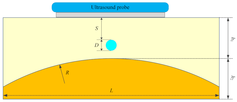
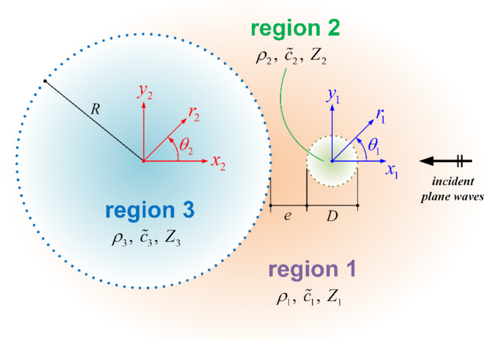
2. Materials and Methods

The complex tissue–implant–bone system was simplified as a 2-D bilayer structure composed of a soft tissue and a bone. As shown in Figure 1, the interface between the tissue and the bone was assumed to be convex with a pre-specified curvature, while a circular inclusion was embedded in the soft tissue. To effectively address and balance these concerns for large-domain simulations, a hybrid computational framework combining two kernels is devised. In the first kernel, theoretical solutions of pressure fields inside/outside the double circular inclusions in the infinite domain under plane-wave incidence are derived. Pressure fields are then transformed into corresponding heat sources. In the second kernel, temperature distributions in the composite media under ultrasound diathermy are evaluated via finite element numerical simulations to heat conduction equations. The details of the proposed method are addressed in the following.

2.1. Pressure Field

A 2-D mixture model for ultrasound propagation is considered as shown in Figure 2. Such a composite medium consists of two circular inclusions (the inclusion and the bone), embedded in an unbounded matrix (tissue). Plane longitudinal ultrasonic waves at normal incidence are assumed, with homogeneous, isotropic, and linearly elastic media.
For the multiple scattering problem under consideration, the standard approach is applied to expand the wave field solutions in terms of the wave functions in polar coordinates. Assuming a time-harmonic dependence for the angular frequency ω, the velocity potential Φj(x, t) describing the motion in each region is given by [22]:
Φ j ( x ,   t ) = Re ϕ j ( x ) exp ( i   ω   t ) ,       j = 1 ,   2 ,   3 ,
where Re[.] denotes the real part of the complex number, Φj(x) is the spatial potential function, and i is the unit imaginary number. Hereafter, the time-harmonic factor exp(iωt) is understood.
Solutions to the Helmholtz equations are sought based on linear acoustics, namely,
2 ϕ j   r 2 + 1 r       ϕ j   r + 1 r 2       2 ϕ j   θ 2 + k ˜ j 2     ϕ j = 0 ,       j = 1 ,   2 ,   3 ,
where k ˜ j = ω / c ˜ j is the wavenumber. Detailed derivations of the theoretical solutions are given in the supplementary data (see Section S1). The corresponding pressure fields can be computed using Equation (1). The pressure values in each region are normalized with respect to the incident amplitude coefficient (i.e., Ainc in Equation (S1) of the Supplementary Data).

2.2. Temperature Field
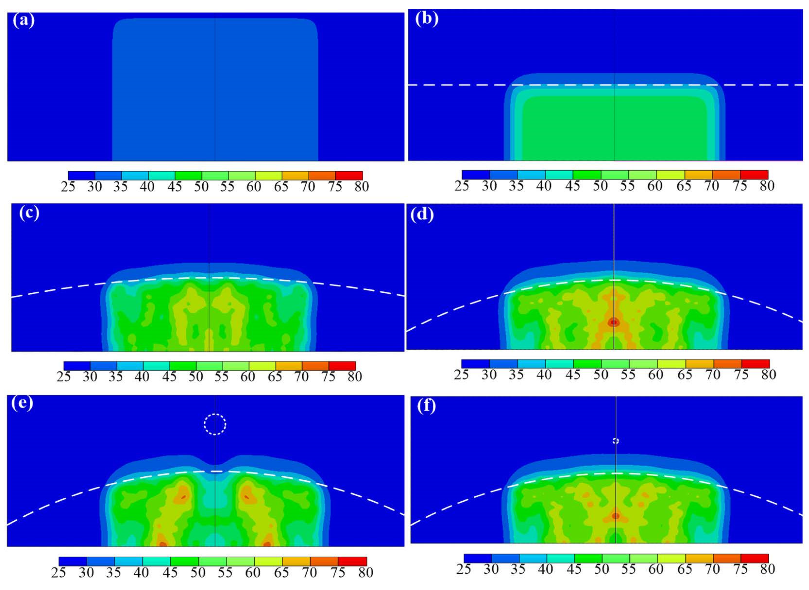
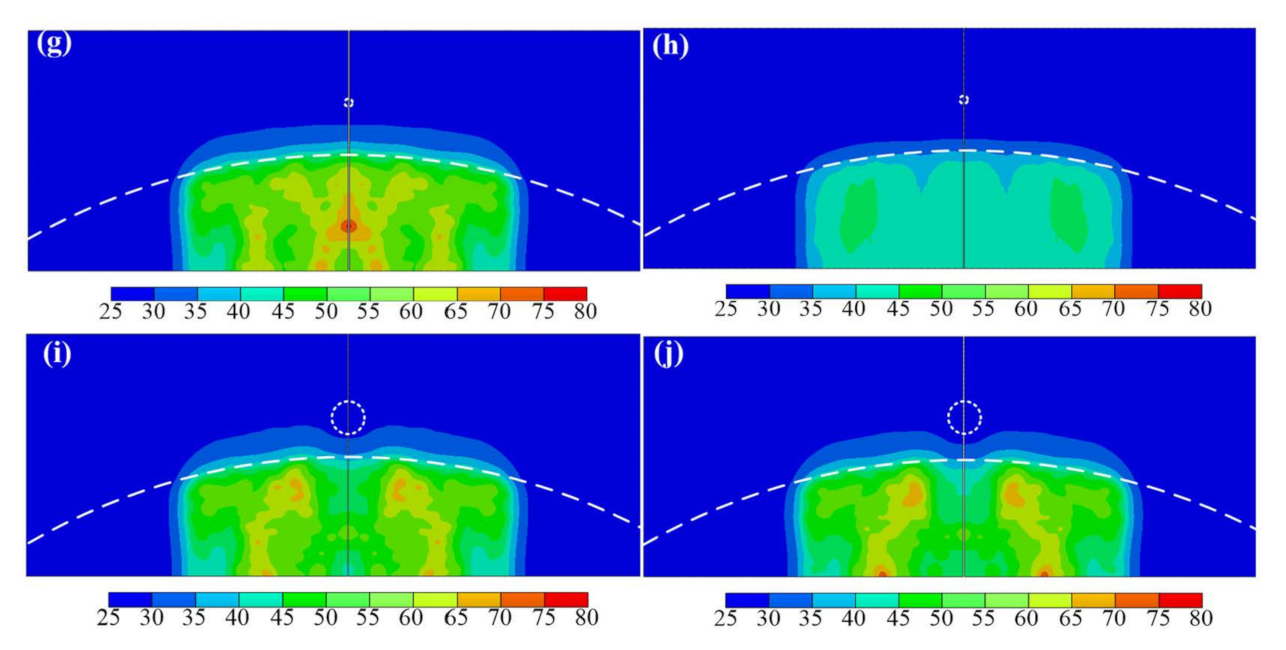
An ultrasound probe was adopted as the target for simulation. The diameter of the ultrasound probe was 40 mm, and the output ultrasound beam was projected in the direction normal to the top surface of the composite system. The composite system was heated for 30 s by an ultrasound probe at the ultrasound intensities of 1.19 and 0.95 W/cm2, at 1 and 3 MHz, respectively [15]. To test extreme conditions, we assume that the ultrasound probe is fixed during the thermal therapy. The initial temperature of the composite system was 26 °C based on the initial ambient temperature considered for the ultrasound heating experiments.
Mathematically, the governing equation of heat conduction in a composite medium with internal heat generation within each layer can be written as [23]:
ρ j   c j T j ( x ,   y ,   t )     t = k j 2 T j ( x ,   y ,   t )     x 2 + k j 2 T j ( x ,   y ,   t )     y 2 + q j ( x ,   y ,   t ) ,       j = 1 ,   2 ,   3 ,
where cj and kj represent the specific heat capacity and the thermal conductivity of the jth material, respectively. In addition, Tj and qj denote the temperature and the rate of heat production per unit volume in the jth material, respectively. Finally, t is the time in seconds.
Owing to the complexity of the expressions for the pressure fields in the present composite model, the theoretical solutions of temperature fields in the corresponding heat conduction problem are inordinately complicated. Consequently, the FE method is used in this study, which is well-suited for the present heating modeling (see Section S2 of the Supplementary Data). A 2-D FE model was constructed using four-node quadrilateral and three-node triangle thermal elements (DC2D4 and DC2D3 in Abaqus [24]) with an element size of 1 × 10⁻⁴ m. The material properties of the soft tissue, inclusion, and bone used in the FE model are listed in Table 1.

3. Results

The accuracy of the proposed computational framework needs to be verified first before performing parametric studies to investigate the effects of the inclusion on the temperature distribution during ultrasound therapies. Theoretical solutions of the pressure fields and the numerically simulated temperature fields in a parallel bilayer system (similar to case b in Table 2), which is a degenerated form of Figure 1 under the plane incident wave from the ultrasound transducer are compared with the experiment data and analytical solutions in the literature [15,17]. Details are shown in Section S3 of the Supplementary Data. Hereafter, a parametric study of the ultrasound diathermy is performed.
The considered composite system, as shown in Figure 1, consists of two layers. The minimum thickness of the soft-tissue layer h1 was 15 mm, while the maximum thickness of the bone layer h2 was 15 mm. In addition, both layers have width, L, of 80 mm. It is noted that the tissue-mimicking hydrogel phantoms are adopted to replace the real soft tissues in this study.
The initial temperature of the composite system was 26 °C based on the initial ambient temperature considered for the ultrasound heating experiments. The temperature of the front surface of the composite system (near the ultrasound transducer) was held constant at 26 °C, while the other three outer surfaces were adiabatic. The area beneath the ultrasound probe was the heating region, with non-uniform heating implemented by the user subroutine DFLUX (see Equation (S21) of the Supplementary Data). A time step of 1.0 s was used in the thermal transient analyses. In addition, to fit the results of the in vitro experiments [15], the amplitude coefficient Ainc (see Equation (S1) of the Supplementary Data) was calibrated to values of 1.9 × 10⁵ and 1.25 × 10⁵ for 1 MHz and 3 MHz ultrasound heating, respectively.
To investigate the effects of different parameters, such as inclusion position S, inclusion size D, inclusion material M, radius of the convex bone R, and ultrasound operation frequency f, on the temperature profiles, a parametric study was performed with ten FE models. The parameters for these ten models are listed in Table 2. The first two cases are the control experiments, in which the composite system is only composed of soft tissue in case a and both the tissue layer and bone layer are flat in case b. It should be noted that an inclusion size of zero denotes a lack of an inclusion and a convex bone with an infinite radius means that the bone is flat. Stainless steel (Steel) and high-density polyethylene (HDPE) were considered as the two inclusion materials. The material properties of the soft tissue, inclusion, and bone used in the FE model are listed in Table 1.
Figure 3a–j present the pressure distributions for ten cases. In these figures, the purple dashed lines represent the interface between the soft tissue and the bone, while the purple dotted lines represent the circumference of the circular inclusions. Note that only the illuminated regions under the ultrasound probe of the composite systems are shown. The pressure values in each region are initially normalized with respect to the incident amplitude coefficient (i.e., Ainc in Equation (S1) of the Supplementary Data). However, for easy comparison of the localized features in these cases, all the pressure values computed are normalized again by an overall maximum value (i.e., 4.607 MPa). In contrast to Figure 3a, Figure 3b–h demonstrate that the pressure clearly increases and has multiple local maxima in the bone layer when the bone layer geometry changes from flat to convex.
In addition, the larger inclusion more prominently disturbs the pressure field in Figure 3a–h. The pressure shielding effect that occurs between the inclusion and the bone layer became more pronounced with increasing inclusion size and distance between the inclusion and the bone layer. The severity of the pressure field disturbance also affects the location of the peak temperature in the composite system. Moreover, when the diameter of the circular inclusion is smaller than the ultrasonic wavelength, the pressure shielding effect can be neglected.
The temperature fields at the end of ultrasound heating for the ten parametric FE models are given in Figure 4a–j. In these figures, the white dashed lines represent the interface between the soft tissue and the bone, while the white dotted lines represent the circumference of the circular inclusions. Except for the control experiment of case a, Figure 4b–j demonstrate that the peak temperatures in the composite systems occurred in the bone layers. In addition, the location of the peak temperature of the composite system moves away from the axis of symmetry due to the pressure shielding effect when the diameter of the inclusion is 4 mm. The shorter the distance between the inclusion and the bone layer is, the less the peak temperature achieves in the bone layer. Table 3 lists the peak temperatures in different materials of these composite systems.

4. Discussion

4.1. Effect of a Flat Bone

Comparing with Figure 4a, one can find that the peak temperature increases from 33.96 °C to 47.90 °C in the composite system, Figure 4b, due to the effect of the planar bone layer. The locations of the peak temperatures both occur at the bottom of the axis of symmetry of these two systems. Moreover, the maximum temperature in the soft-tissue layer, which moves from the bottom of the symmetric axis to the intersection of the axis of symmetry and the interface of the composite system, is 33.96 °C and 35.62 °C for the tissue-only system and the bilayer system, respectively.

4.2. Effect of a Convex Bone

From Figure 4b–d, the peak temperatures are all found to occur in the bone layer of the composite systems. In addition, the peak temperature in the tissues increases from 35.62 °C in case b to 41.55 °C in case c and to 45.38 °C in case d. The location of the peak temperature of the composite system moves from the bottom to the middle part of the bone layer along the axis of symmetry of the composite system when the bottom layer varies from a flat bone to a convex bone with a radius of 80 mm. In addition, the maximum temperature in the soft-tissue layer, which occurs at the intersection of the axis of symmetry and the interface of the composite system, is 35.62 °C, 41.55 °C, and 42.34 °C for the planar bone layer and convex bone layer with radii 8000 mm, 200 mm and 80 mm, respectively. These results demonstrate that a large curvature of the convex bone layer increases the peak temperature of the soft-tissue layer during thermal therapies.

4.3. Effect of the Inclusion Size

From Figure 4d,g,j, it is observed that the peak temperature of the composite system moves from the middle part of the bone to the bottom of the bone layer as the inclusion diameter increases to 4 mm. The peak temperature is on the bottom edge of the composite system away from the axis of symmetry. Moreover, the peak temperatures in the bone layer decrease from 77.04 °C to 75.54 °C when the inclusion diameter increases from 0 mm to 1 mm, and then further decreases to 71.69 °C for an inclusion diameter of 4 mm. The maximum temperature in the soft-tissue layer moves away the axis of symmetry of the composite and decreases from 42.34 °C to 41.77 °C to 41.17 °C with increasing inclusion diameter. These results indicate that the presence of the inclusion changes not only the peak temperature but also the temperature distribution when the inclusion is sufficiently large.

4.4. Effect of the Inclusion Location

The effects of the inclusion location on the temperature distribution can be obtained by comparing Figure 4e). The temperature distribution pattern changes slightly when the inclusion moves from 4 mm to 8 mm toward the bone layer. The location of the peak temperature of the composite system remains at the bottom of the bone layer when the inclusion moves along the axis of symmetry. The peak temperature of the composite system decreases from 73.64 °C to 71.69 °C when the inclusion moves from 4 mm to 8 mm toward the bone layer. In addition, the maximum temperature in the soft-tissue layer increases from 41.34 °C to 41.77 °C and the corresponding peak location remains at the same distance from the axis of symmetry as the inclusion moves forward in the bone layer diameter.

4.5. Effect of the Inclusion Material

By comparing Figure 4f,g,i and j, the effect of the inclusion material on the temperature distribution can be observed. The temperature distribution pattern changes slightly when the inclusion material changes from HDPE to stainless steel. The peak temperatures in the tissue and bone layers of the composite system with a circular HDPE inclusion are lower than that with a circular stainless-steel inclusion. However, the peak temperatures in HDPE inclusions are higher than those in stainless steel inclusions. These contrast to those obtained in previous studies using a plate implant [15,17]. The contrary peak temperatures resulting from the inclusion material can be mainly attributed to differences in inclusion sizes. The circular inclusion sizes in this study are considerably smaller than the sizes of the plate implants used in previous studies, which results in a lessened influence on the temperature distribution during ultrasound diathermy.

4.6. Effect of the Ultrasound Operation Frequency

The effect of ultrasound operation frequency on the temperature distribution can be obtained by comparing Figure 4g,h. The temperature distribution pattern changes significantly when the ultrasound operation frequency changes from 1 MHz to 3 MHz. The temperature of the composite system with a circular stainless-steel inclusion for the 3 MHz ultrasound is lower than that for the 1 MHz ultrasound. With a circular stainless-steel inclusion, the peak temperature decreases dramatically from 75.54 °C to 47.38 °C when the ultrasound operation frequency increases from 1 MHz to 3 MHz. However, it is worth noting that these results were obtained from the ultrasound transducer operation under the specific powers. Different ultrasonic powers may lead to different results.

5. Conclusions

The effects of a circular inclusion on temperature distribution in a tissue–bone composite structure during ultrasound diathermy were investigated in this study. This composite system was simplified as a bilayer system consisting of a soft tissue attached with a bone having a pre-specified curvature. A hybrid computational framework was proposed herein to investigate the effect of double circular inclusions on the temperature distribution during ultrasound diathermy. Numerical results demonstrate that the presence of the inclusion changes both the peak temperature and the temperature distribution when the inclusion is sufficiently large relative to the ultrasonic wavelength. The peak temperature in the composite system decreases when the inclusion is closer to the bone layer. The peak temperature of the composite system with a circular HDPE inclusion is lower than with a circular stainless-steel inclusion. Finally, the temperature of the composite system with a circular stainless-steel inclusion with a 3 MHz ultrasound is lower than under a 1 MHz ultrasound.
Our simulation results indicate that determining the temperature distribution in the human body is a complex challenge. The scattering or focusing of ultrasonic energy is dominated by the geometries of the inclusion and bone layer. The proposed computational framework could also provide fundamental understanding of the thermal therapy and lay the foundation for implant design and clinical strategies in related treatments. Clearly, the proposed hybrid scheme is applicable to inclusions with simple geometric shapes. This is because the near-field acoustic pressure computation relies on analytical solutions derived or those obtained in the literature. The 2-D extended topics cover semicircular inclusions, elliptical inclusions, semi-elliptical inclusions, truncated circular inclusions, truncated elliptical inclusions, multiple inclusions (with above shapes), multilayer composites, coated cavities, and any combination of the above.

Supplementary Materials

The following supporting information can be downloaded at: https://www.mdpi.com/article/10.3390/app12105166/s1, Section S1: Formulation for Pressure Fields; Section S2: Formulation for Temperature Fields; Section S3: Verification; Section S4: Limitations of the Proposed Computational Framework; Figure S1: Temperature history curves and temperature distribution curves; Figure S2: Pressure distribution; Figure S3: Temperature distribution. References [25,26,27,28,29,30] are cited in the Supplementary Materials.

Author Contributions

C.-W.H. organized this work and performed numerical simulations. K.-H.C. derived analytical solutions for the pressure fields. C.-W.H. and K.-H.C. wrote the manuscript. All authors have read and agreed to the published version of the manuscript.

Funding

The authors acknowledge the financial support of the Ministry of Science and Technology (MOST 106-2221-E-033-034-MY3, MOST 109-2224-E-080-001, and MOST 105-2221-E-033-008), Taiwan. This research is also partially supported by the John and Wen Su Term Research Acceleration Fund, and by Su Development.

Institutional Review Board Statement

Not applicable.

Informed Consent Statement

Not applicable.

Data Availability Statement

The data presented in this study are available on request from the corresponding author.

Acknowledgments

The authors are grateful to Simutech Solution Corporation and the National Center for High-performance Computing for providing computational resources. Special thanks goes to the support from the Office of Research and Development at Chung Yuan Christian University (Project Nos. 107011041, 107011042, 107011051, 107011052, and 110-CYCU-RG2-14).

Conflicts of Interest

The authors declare no conflict of interest.

References

  1. Hayes, B.T.; Merrick, M.A.; Sandrey, M.A.; Cordova, M.L. Three-MHz ultrasound heats deeper into the tissues than originally theorized. J. Athl. Train. 2004, 39, 230–234. [Google Scholar]
  2. Draper, D.O.; Castel, J.C.; Castel, D. Rate of temperature increase in human muscle during 1 MHz and 3 MHz continuous ultrasound. J. Orthop. Sports Phys. Ther. 1995, 22, 142–150. [Google Scholar] [CrossRef]
  3. Draper, D.O.; Sunderland, S.; Kirkendall, D.T.; Ricard, M. A comparison of temperature rise in human calf muscles following applications of underwater and topical gel ultrasound. J. Orthop. Sports Phys. Ther. 2017, 17, 247–251. [Google Scholar] [CrossRef]
  4. Oliveira, D.P.; Areias, L.M.A.; Pereira, W.C.A.; von Krüger, M.A. Therapeutic ultrasound heat propagation in a cylindrical four-layer phantom. In Proceedings of the XXIV Brazilian Congress on Biomedical Engineering (CBEB 2014), Armação de Buzios, Brazil, 21–25 October 2014; Volume 1037, p. 41. [Google Scholar]
  5. Speed, C.A. Therapeutic ultrasound in soft tissue lesions. Rheumatology 2001, 40, 1331–1336. [Google Scholar] [CrossRef] [Green Version]
  6. Swanson, A.B.; Maupin, B.K.; Gajjar, N.V.; de Groot Swanson, G. Flexible implant arthroplasty in the proximal interphalangeal joint of the hand. J. Hand Surg. Am. 1985, 10, 796–805. [Google Scholar] [CrossRef]
  7. Cofield, R.H.; Edgerton, B.C. Total shoulder arthroplasty: Complications and revision surgery. Instr. Course Lect. 1990, 39, 449–462. [Google Scholar]
  8. Ghidella, S.D.; Segalman, K.A.; Murphey, M.S. Long-term results of surgical management of proximal interphalangeal joint contracture. J. Hand Surg. Am. 2002, 27, 799–805. [Google Scholar] [CrossRef] [Green Version]
  9. Planas, J. Prophylactic use of external ultrasound for breast implant capsular contracture. Aesthet. Surg. J. 2002, 22, 205–207. [Google Scholar] [CrossRef]
  10. Cameron, M.H. Physical Agents in Rehabilitation: From Research to Practice, 4th ed.; Elsevier/Saunders: St. Louis, MO, USA, 2012; pp. 185–214. [Google Scholar]
  11. Gersten, J.W. Effect of metallic objects on temperature rises produced in tissue by ultrasound. Am. J. Phys. Med. Rehabil. 1958, 37, 75–82. [Google Scholar] [CrossRef]
  12. Brunner, G.D.; Lehmann, J.F.; McMillan, J.A.; Lane, K.E.; Bell, J.W. Can ultrasound be used in the presence of surgical metal implants: An experimental approach. Phys. Ther. 1958, 38, 823–824. [Google Scholar] [CrossRef]
  13. Lehmann, J.F.; Brunner, G.D.; McMillan, J.A. Influence of surgical metal implants on the temperature distribution in thigh specimens exposed to ultrasound. Arch. Phys. Med. Rehabil. 1958, 39, 692–695. [Google Scholar]
  14. Lehmann, J.F.; Lane, K.E.; Bell, J.W.; Brunner, G.D. Influence of surgical metal implants on the distribution of the intensity in the ultrasonic field. Arch. Phys. Med. Rehabil. 1958, 39, 756–760. [Google Scholar]
  15. Sun, M.K.; Shieh, J.; Chen, C.S.; Chiang, H.G.; Huang, C.W.; Chen, W.S. Effects of an implant on temperature distribution in tissue during ultrasound diathermy. Ultrason. Sonochem. 2016, 32, 44–53. [Google Scholar] [CrossRef]
  16. Andrades, A.O.; Mazzanti, A.; Beckmann, D.V.; Aiello, G.R.; Chaves, O.; Santos, R.P. Heating produced by therapeutic ultrasound in the presence of a metal plate in the femur of canine cadavers. Arq. Bras. Med. Vet. Zootec. 2014, 66, 1343–1350. [Google Scholar] [CrossRef]
  17. Huang, C.W. Simplified theoretical model for temperature evaluation in tissue–implant–bone systems during ultrasound diathermy. Appl. Sci. 2020, 10, 1306. [Google Scholar] [CrossRef] [Green Version]
  18. de Araújo Loures, E.; Costa, F.B.; Júnior, A.F.M.; Rocha, G.M.; Loures, D.N. Fatigue fracture of femoral stem in total hip arthroplasty after use of ultrasound: A case report. Int. J. Case Rep. Images 2018, 9, 100923Z01EL2018. [Google Scholar]
  19. Moros, E.G.; Straube, W.L.; Myerson, R.J.; Fan, X. The impact of ultrasonic parameters on chest wall hyperthermia. Int. J. Hyperth. 2000, 16, 523–538. [Google Scholar] [CrossRef]
  20. Moros, E.G.; Novak, P.; Straube, W.L.; Kolluri, P.; Yablonskiy, D.A.; Myerson, R.J. Thermal contribution of compact bone to intervening tissue-like media exposed to planar ultrasound. Phys. Med. Biol. 2004, 49, 869–886. [Google Scholar] [CrossRef]
  21. Omena, T.P.; Fontes-Pereira, A.J.; Costa, R.M.; Simões, R.J.; von Krüger, M.A.; Pereira, W.C.A. Why we should care about soft tissue interfaces when applying ultrasonic diathermy: An experimental and computer simulation study. J. Ther. Ultrasound. 2017, 5, 1–6. [Google Scholar] [CrossRef] [Green Version]
  22. Varadan, V.V.; Ma, Y.; Varadan, V.K.; Lakhtakia, A. Scattering of waves by spheres and cylinders. In Field Representations and Introduction to Scattering; Elsevier Science: New York, NY, USA, 1991; pp. 211–324. [Google Scholar]
  23. Hahn, D.W.; Özisik, M.N. Heat Conduction, 3rd ed.; John Wiley & Sons: New York, NY, USA, 2012. [Google Scholar]
  24. SIMULIA-Abaqus 2020 User’s Manual; Dassault Syst′emes Simulia, Inc.: Providence, RI, USA, 2020.
  25. Gradshteyn, I.S.; Ryzhik, I.M. Table of Integrals, Series and Products, 7th ed.; Elsevier-Academic Press: Amsterdam, The Netherlands, 2007. [Google Scholar]
  26. Jacobsen, F.; Juhl, P.M. Fundamentals of General Linear Acoustics; John Wiley & Sons: London, UK, 2013; pp. 171–186. [Google Scholar]
  27. Watson, G.N. A Treatise on the Theory of Bessel Functions, 2nd ed.; Cambridge University Press: Cambridge, UK, 1966. [Google Scholar]
  28. Lebedev, N.N. Special Functions and Their Applications; Selected Russian Publications in the Mathematical Sciences; Silverman, R.A., Ed.; Prentice-Hall, Inc.: Englewood Cliffs, NJ, USA, 1965. [Google Scholar]
  29. Nyborg, W.L. Heat generation by ultrasound in a relaxing medium. J Acoust. Soc. Am. 1981, 70, 310–312. [Google Scholar] [CrossRef]
  30. Meaney, P.M.; Clarke, R.L.; Haar, G.R.T.; Rivens, I.H. A 3-D finite-element model for computation of temperature profiles and regions of thermal damage during focused ultrasound surgery exposures. Ultrasound Med. Biol. 1998, 24, 1489–1499. [Google Scholar] [CrossRef]
Figure 1. Schematic illustration of a bilayer composite medium with a circular inclusion subjected to ultrasound plane waves.
Applsci 12 05166 g001
Figure 2. Geometric layout of the mixture model for ultrasound propagation.
Applsci 12 05166 g002
Figure 3. Normalized pressure distributions in the composite systems (Cases (aj)).
Applsci 12 05166 g003aApplsci 12 05166 g003b
Figure 4. Temperature distributions (unit: °C) in the composite system at the end of the ultrasound diathermy (Cases (aj)).
Applsci 12 05166 g004aApplsci 12 05166 g004b
Table 1. Material properties of the soft tissue, inclusions, and bone [17].
Material PropertyTissueStainless SteelHDPEBone
Density (kg/m3)119077109601912
Specific heat (J/kg °C)343150223001313
Speed of sound (m/s)1512579024604400
Thermal conductivity (W/m °C)0.616.270.4420.32
Attenuation coefficient (db/m)5412466900
Table 2. Parameters used in the ten simulation scenarios.
ModelS (mm)D (mm)MR (mm)h1 (mm)h2 (mm)f (MHz)
Case a00-infinity3001
Case b00-infinity15151
Case c00-20015151
Case d00-8015151
Case e44Steel8015151
Case f81HDPE8015151
Case g81Steel8015151
Case h81Steel8015153
Case i84HDPE8015151
Case j84Steel8015151
Table 3. Peak temperatures in different materials under ten simulation scenarios.
ModelTissueInclusionBone
Case a33.96̶̶
Case b35.62̶47.90
Case c41.55̶64.86
Case d42.34̶77.04
Case e41.4327.7773.64
Case f40.6728.7373.66
Case g41.7728.5375.54
Case h34.3227.0247.38
Case i42.2229.3567.11
Case j41.1728.3271.69
Publisher’s Note: MDPI stays neutral with regard to jurisdictional claims in published maps and institutional affiliations.

