3.1. Cascade Discharge
It is shown in
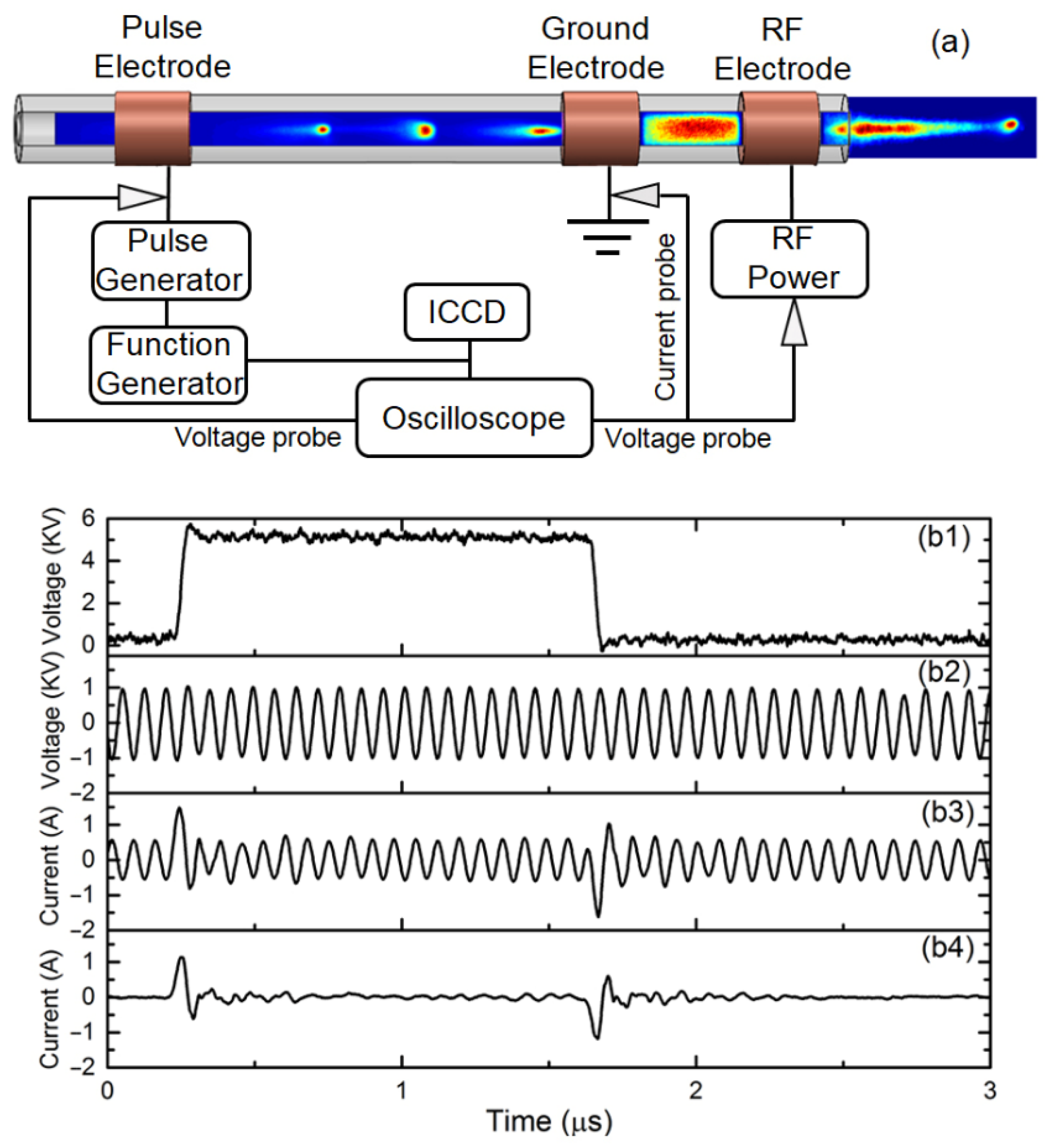
Figure 1a that the pulsed discharge is generated between the pulse electrode and ground electrode in terms of a travelling plasma bullet and the RF discharge is ignited between the RF electrode and ground electrode. At the exit of the tube, the plasma plume can be attributed to both the RF discharge and pulsed discharge, which will be characterized by the spatio-temporal evolution of the discharge. The waveform of the pulse voltage, as shown in
Figure 1(b1), has the amplitude of 5.2 kV and duration of 1.4 μs with the duty cycle of 0.7%. The waveform of the RF voltage with the amplitude of 1.0 kV is shown in
Figure 1(b2). In the experiments, the duty cycle of the pulse voltage was changed to manipulate the length of the pulsed discharge while keeping other discharge parameters unchanged.
Figure 1(b3) gives the waveform of the total discharge current collected from the ground electrode, which includes the pulsed discharge current and RF discharge current. There are two current peaks with amplitudes of 1.5 A and 1.6 A at the time instants of 0.24 μs and 1.64 μs, respectively, which correspond to the rising phase and falling phase of the pulse voltage, as shown in
Figure 1(b1). By subtracting the stable operation of the RF discharge current with the amplitude of 0.5 A from the total discharge current, the pulsed discharge current can be obtained, with two current peaks with amplitudes of 1.1 A and 1.2 A, as shown in
Figure 1(b4), which is consistent with that in the dielectric barrier pulsed discharge [
8].
To demonstrate the enhancement of the pulsed discharge on the RF discharge and plasma plume, the pulsed discharge was manipulated to propagate into the pulsed discharge region, RF discharge region, and plasma plume region, by changing the duty cycle of the pulse voltage, as shown in
Figure 2(a1–c1), respectively. With a duty cycle of 0.3%, corresponding to the pulse voltage duration of 0.6 μs, as shown in
Figure 2(a1), the pulse discharge does not reach the ground electrode, and the plasma plume with the length of 2.0 mm can be attributed mostly to the RF discharge. The temporal evolution of discharges is presented in
Figure 2(a2) with the time resolution of 10 ns, which is the exposure time of the ICCD camera and the time interval between two consecutive discharge images. The dashed lines in the figure indicate the position of the electrodes and the nozzle of the tube. The pulsed discharge can be recognized as a travelling plasma bullet, which is ignited near the pulsed electrode and reaches the position of 20 mm with the time interval of 0.6 μs [
13]. The RF discharge and plasma plume keep their spatial profile and intensity within 4.0 μs of the ignition of the pulsed discharge, which suggests that the operation of the RF discharge is independent of the pulsed discharge. It is worth noting that the image intensities of the pulsed discharge and plasma plume are reduced and elevated by 10 times, respectively, for better demonstration, as indicated in
Figure 2(a2).
With the duty cycle of 0.7%, corresponding to the pulse voltage duration of 1.4 μs, as shown in
Figure 2(b1), the pulsed discharge reaches the ground electrode. It also shows that the intensity of the plasma plume is enhanced in terms of plume length growing to 4.0 mm.
Figure 2(b2) gives the temporal evolution of discharge, which demonstrates the interaction between the pulsed plasma bullet with RF discharge. The plasma bullet generated in the pulsed discharge region enters into the RF discharge region at the time instant of 1.2 μs and leaves the RF electrode at the time instant of 1.7 μs. With the propagation of the plasma bullet in the RF discharge region, the intensity of the RF discharge is enhanced from the ground electrode to the RF electrode and maintains a time delay. At the time instant of 2.0 μs, the intensity of the plasma plume outside of the tube nozzle grows due to the enhancement of the RF discharge by the pulsed discharge. When increasing the duty cycle to 1.2% with the pulse voltage duration of 2.4 μs, as shown in
Figure 2(c1), the pulsed plasma bullet passes through the RF discharge region and moves out of the tube. The plasma plume is composed of the pulsed plasma bullet and RF discharge plume, which can be recognized by the discharge temporal evolution, as shown in
Figure 2(c2) [
14]. The RF discharge is enhanced with the passage of the pulsed plasma bullet, which is consistent with the result shown in
Figure 2(b2), except for the interference by the pulsed discharge at the time instant of 2.6 μs, corresponding to the falling phase of the pulse voltage. The intensity of the plasma bullet is reduced by 10 times in the plasma plume region outside of the tube, which shows the propagation of the plasma bullet with the length of 14 mm. The intensity of the RF discharge plume is elevated by two times to distinguish from the pulsed plasma bullet, which also shows the intensification of the RF discharge plume with the enhancement of the RF discharge. The length of the RF discharge plume is estimated to be 6.0 mm.
The discharge maximum image intensities at each time instant in the regimes of pulsed discharge, RF discharge, and plasma plume are presented in
Figure 3 as a function of the duration of the voltage pulse. In the regime of the pulsed discharge, the discharge image intensity grows from 58 to 860 when increasing the duty cycle from 0.4 μs to 1.0 μs, which corresponds to the growth of the pulsed plasma bullet from ignition in the vicinity of the pulsed electrode until reaching the ground electrode. As the duty cycle further increases to 2.4 μs, the pulsed plasma bullet travels through the regime of pulsed discharge, and the discharge image intensity changes slowly to 1000. In the regime of RF discharge, before the duty cycle reaches below 1 μs, the discharge image intensity maintains a low magnitude of around 23, which is elevated with the injection of the pulsed plasma bullet and reaches the magnitude of 47 at the duty cycle of 1.4 μs. It is proposed that the enhancement in the RF discharge image intensity by two times can be attributed to the injection of the pulsed plasma bullet. With the duty cycle increasing to 2.4 μs, the discharge image intensity reaches 65, which is more than one order of magnitude lower than that of the pulsed discharge. In the regime of the plasma plume, the discharge image intensity is as low as 4, which is much lower than that of the pulsed plasma bullet and can be distinguished from the pulsed plasma bullet. With the enhancement in the RF discharge, the discharge image intensity is elevated to 7 at the duty cycle of 1.4 μs, which is further elevated to 23 at the duty cycle of 2.4 μs with the assistance of the pulsed plasma bullet. This suggests that the intensified RF discharge and plasma plume can be achieved with the propagation of the pulsed plasma bullet through the RF discharge regime and plasma plume regime.
Figure 4 shows the spatio-temporal evolution of the plasma plume with a pulse duty cycle of 1.2% and duration of 2.4 μs at the nozzle. The exposure time was set to 20 ns for pulsed discharge and 500 ns for RF discharge during the experiment. The vertical dashed line in the figure indicates the position of the nozzle of the discharge tube. It is divided into three time domains for better demonstration: the stable RF discharge plume (−20~0 μs), the pulsed plasma bullet passing through the RF plume (0~4 μs), and the RF plume affected by the plasma bullet (4~60 μs). The stable RF discharge plume has a low plasma intensity and the plume length is approximately 2 mm. The image of the pulsed plasma bullet passing through the RF discharge plume is shown in
Figure 2(c2). The length of the RF discharge plume increases to 6 mm with the injection of the pulsed plasma bullet. After the pulsed plasma bullet passes through the RF discharge plume, the influence of pulsed discharge on the RF discharge plume gradually decreases, and the intensity of the RF discharge plume gradually decreases. The inserted images show the plasma plumes with the accumulation of image intensity between −12 μs and −8 μs, between 0 μs and 3 μs, and between 8 μs and 12 μs, respectively. The length of the RF discharge plume increases from 2 mm to 6 mm. It is demonstrated that the intensity and length of the RF discharge plume increase with the injection of pulsed plasma bullets, and this enhancement can last tens of microseconds after the pulsed plasma bullet has been extinguished.
3.2. Carbon Fiber Treatment
The enhancement of the RF discharge plume can also be demonstrated by the optical emission intensities at the nozzle in
Figure 4. The behaviors of the optical emission intensities of 706 and 777 nm at the nozzle are further shown in
Figure 5. The optical emission line at 706 nm is attributed to the transition of He (3
3S
1→2
3P
0,1,2); it is agreed that the intensity of the optical emission line at 706 nm is an indication of the presence of electrons with energies above 2.9 eV. The optical emission line at 777 nm is attributed to the transition of O (3s
5S
0→3p
5P). It can be found that when the pulse duration is below 1.2 μs, the intensity of high-energy electrons at the nozzle is proposed to be extremely low. When the pulse duration is greater than 1.2 μs, the pulsed plasma bullet reaches the outside of the tube and the optical emission intensity at 706 nm increases from 15 to 85. Meanwhile, the optical emission intensity at 777 nm increases from 42 to 57, which indicates that the injection of the pulsed plasma bullet results in the enhancement in the RF discharge plume.
Atmospheric pressure plasmas have been used for the etching and modification of carbon fibers (CFs) in the ambient air condition, and it is agreed that the surface modification is caused by the chemical reactions of oxygen-containing reactive species with the CFs. It has been proven that the amount of active oxygen in the RF discharge plume with the injection of the pulsed plasma bullet is elevated by 36%, as shown in
Figure 5. These reactive O atoms are believed to play an important role in the surface etching and modification of CFs [
15]. XPS was used to study the chemical composition of CFs before and after cascade plasma plume treatment. The surfaces of CFs mainly contain three types of atoms: C, O, and N. The relative content of each atom is shown in
Figure 6a. The C, O, and N atoms of the untreated CFs are 85.18%, 11.92%, and 2.90%, respectively. After plasma treatment under different pulse durations for 24 s, the oxygen concentration on the surface increased, while the carbon concentration decreased. As the pulse duration increases from 0.6 μs to 2.4 μs, the carbon concentration on the carbon fiber surface decreases from 84.03% to 78.80%, the oxygen concentration increases from 12.98% to 17.92%, and the O1s/C1s ratio grows from 13.99% to 22.74%, respectively. Both the increments in the oxygen concentration and the O1s/C1s ratio indicate that plasma treatment introduces extra oxygen-containing polar groups on the surfaces of CFs. For comparison, a pulsed discharge jet with the pulse duration of 2.4 μs was used to treat the CFs. Although the pulse discharge can also elevate the O1s/C1s ratio of the CF surface, the effect is not as strong as that of the cascade plasma plume. To further investigate the chemical changes of the CF surfaces induced by the cascade plasma plume, deconvolution analyses of the C1s peaks were performed. According to previous reports [
16], four peaks (C-C (284.6 eV), C-O-C (285.9 eV), C=O (287.1 eV), and COOH or COOR (288.5 eV)) can be deconvoluted from the C1s spectra.
Figure 6b gives the curve fitting results of the C1s envelope. It shows that the peak area of COOH or COOR components increased significantly with cascade plasma plume treatment at the pulse duration of 0.6 μs and 1.2 μs. The peak area of C-O and COOH or COOR components is dominated at the pulse duration of 2.4 μs. On the other hand, it is found that the component peak area of the C-O increased significantly when treated by the pulsed discharge jet, which contains travelling plasma bullets. This suggests that the introduction of oxygen-containing polar groups on the CF surface differs from the pulsed discharge jet and the RF discharge plume. The RF discharge plume improves COOH or COOR oxygen-containing polar groups, and the pulse discharge jet mainly increases the density of C-O single bonds on the CF surface. This suggests that with the cascade plasma treatment with both plasma bullets generated by the pulsed discharge and RF discharge plume, more oxygen-containing polar groups are introduced onto the surfaces of CFs.

